EP2782230A2 - Virtueller elliptischer Motor - Google Patents
Virtueller elliptischer Motor Download PDFInfo
- Publication number
- EP2782230A2 EP2782230A2 EP14155850.2A EP14155850A EP2782230A2 EP 2782230 A2 EP2782230 A2 EP 2782230A2 EP 14155850 A EP14155850 A EP 14155850A EP 2782230 A2 EP2782230 A2 EP 2782230A2
- Authority
- EP
- European Patent Office
- Prior art keywords
- gear
- plate
- wobble plate
- rotational output
- fulcrum
- Prior art date
- Legal status (The legal status is an assumption and is not a legal conclusion. Google has not performed a legal analysis and makes no representation as to the accuracy of the status listed.)
- Withdrawn
Links
- 238000000034 method Methods 0.000 claims abstract description 77
- 230000004044 response Effects 0.000 claims abstract description 17
- 230000009977 dual effect Effects 0.000 claims description 5
- 230000008878 coupling Effects 0.000 claims description 4
- 238000010168 coupling process Methods 0.000 claims description 4
- 238000005859 coupling reaction Methods 0.000 claims description 4
- 230000004913 activation Effects 0.000 claims 1
- 230000008569 process Effects 0.000 description 37
- 230000005291 magnetic effect Effects 0.000 description 7
- 239000000463 material Substances 0.000 description 2
- 229910052761 rare earth metal Inorganic materials 0.000 description 2
- 150000002910 rare earth metals Chemical class 0.000 description 2
- 230000008859 change Effects 0.000 description 1
- 238000007796 conventional method Methods 0.000 description 1
- 238000013461 design Methods 0.000 description 1
- 238000005516 engineering process Methods 0.000 description 1
- 230000005294 ferromagnetic effect Effects 0.000 description 1
- 238000005259 measurement Methods 0.000 description 1
- 238000012986 modification Methods 0.000 description 1
- 230000004048 modification Effects 0.000 description 1
- 238000012545 processing Methods 0.000 description 1
- 238000004804 winding Methods 0.000 description 1
Images




Classifications
-
- H—ELECTRICITY
- H02—GENERATION; CONVERSION OR DISTRIBUTION OF ELECTRIC POWER
- H02K—DYNAMO-ELECTRIC MACHINES
- H02K41/00—Propulsion systems in which a rigid body is moved along a path due to dynamo-electric interaction between the body and a magnetic field travelling along the path
- H02K41/06—Rolling motors, i.e. motors having the rotor axis parallel to the stator axis and following a circular path as the rotor rolls around the inside or outside of the stator ; Nutating motors, i.e. having the rotor axis parallel to the stator axis inclined with respect to the stator axis and performing a nutational movement as the rotor rolls on the stator
- H02K41/065—Nutating motors
-
- F—MECHANICAL ENGINEERING; LIGHTING; HEATING; WEAPONS; BLASTING
- F16—ENGINEERING ELEMENTS AND UNITS; GENERAL MEASURES FOR PRODUCING AND MAINTAINING EFFECTIVE FUNCTIONING OF MACHINES OR INSTALLATIONS; THERMAL INSULATION IN GENERAL
- F16C—SHAFTS; FLEXIBLE SHAFTS; ELEMENTS OR CRANKSHAFT MECHANISMS; ROTARY BODIES OTHER THAN GEARING ELEMENTS; BEARINGS
- F16C17/00—Sliding-contact bearings for exclusively rotary movement
- F16C17/04—Sliding-contact bearings for exclusively rotary movement for axial load only
-
- F—MECHANICAL ENGINEERING; LIGHTING; HEATING; WEAPONS; BLASTING
- F16—ENGINEERING ELEMENTS AND UNITS; GENERAL MEASURES FOR PRODUCING AND MAINTAINING EFFECTIVE FUNCTIONING OF MACHINES OR INSTALLATIONS; THERMAL INSULATION IN GENERAL
- F16C—SHAFTS; FLEXIBLE SHAFTS; ELEMENTS OR CRANKSHAFT MECHANISMS; ROTARY BODIES OTHER THAN GEARING ELEMENTS; BEARINGS
- F16C35/00—Rigid support of bearing units; Housings, e.g. caps, covers
- F16C35/02—Rigid support of bearing units; Housings, e.g. caps, covers in the case of sliding-contact bearings
-
- H—ELECTRICITY
- H02—GENERATION; CONVERSION OR DISTRIBUTION OF ELECTRIC POWER
- H02K—DYNAMO-ELECTRIC MACHINES
- H02K2205/00—Specific aspects not provided for in the other groups of this subclass relating to casings, enclosures, supports
- H02K2205/03—Machines characterised by thrust bearings
Definitions
- Embodiments of the present disclosure relate generally to electric motors. More particularly, embodiments of the present disclosure relate to switched reluctance electric motors.
- An electric motor creates a mechanical force from electromagnetic current.
- An alternating current (AC) electric motor generally comprises a stationary stator and a rotor.
- the stationary stator generally comprises electrical wire coils supplied with alternating current producing a rotating magnetic field.
- the rotor is attached to an output shaft that is given a torque by the rotating magnetic field.
- a type of electric motor is a reluctance motor that generates torque through magnetic reluctance.
- a reluctance motor induces non-permanent magnetic poles on a ferromagnetic rotor.
- Existing reluctance motors generally have a high torque ripple, where a difference between maximum and minimum torque during one revolution is high when operated at low speed.
- electro-mechanical motors that are small, low weight, high torque, and can operate at low speed.
- electro-mechanical motors to provide actuation that can be low vibration, jam free and/or tolerant, and provide high holding load capability.
- a virtual ellipse electric motor and methods are presented.
- a fulcrum bears a nutating dynamic load, and a wobble plate is rotationally coupled to the fulcrum and nutates around the fulcrum.
- the wobble plate comprises an inner pericyclic gear and an outer pericyclic gear.
- a stationary gear meshes with the outer pericyclic gear and provides leverage to the wobble plate.
- the rotational output plate meshes with the inner pericyclic gear and rotates in response to nutation of the wobble plate.
- a stator comprises an electromagnet and electromagnetically attracts a first side of the wobble plate such that a second side of the wobble plate is leveraged against the stationary gear and the rotational output plate.
- embodiments of the disclosure provide a high torque low speed electro-mechanical motor that performs as well or better than hydraulic actuation with power and energy density equal to or greater than hydraulic actuation.
- Existing switched reluctance motors do not provide guaranteed starting, controlled starting direction and reversing capability with less than 6 stator poles and 4 rotor poles.
- Embodiments of the disclosure can achieves guaranteed starting, controlled starting direction and reversing capability with 6 stator poles and one virtual rotor pole, and do not require and may be configured without rotor poles, but nonetheless can provide starting, holding, reversing as well as or better than existing motors.
- Embodiments of the disclosure provide an electric motor that need not use expensive rare earth metals, and provides low vibration, and substantially jam free and/or jam tolerant high holding load capability.
- the electric motor can de-couple from an output shaft when in a non-optimal condition or de-powered mechanically, and is electrically robust.
- a virtual ellipse electric motor comprises a fulcrum, a wobble plate, a stationary gear, a rotational output plate, and a stator.
- the fulcrum bears a rotating radial dynamic load.
- the wobble plate is rotationally coupled to the fulcrum and nutates around the fulcrum, and comprises an inner pericyclic gear and an outer pericyclic gear.
- the stationary gear meshes with the outer pericyclic gear and provides leverage to the wobble plate.
- the rotational output plate meshes with the inner pericyclic gear and rotates in response to nutation of the wobble plate.
- the stator comprises an electromagnet and electromagnetically attracts a first side of the wobble plate such that a second side of the wobble plate is leveraged against the stationary gear and the rotational output plate.
- a method for operating a virtual ellipse electric motor nutates a wobble plate rotationally coupled to a fulcrum around the fulcrum, the wobble plate comprising an inner pericyclic gear and an outer pericyclic gear.
- the method further electromagnetically attracts a first side of the wobble plate to a stator comprising an electromagnet.
- the method further leverages the wobble plate with the fulcrum to press a second side of the wobble plate against the stationary gear and a rotational output plate.
- the method further meshes a stationary gear with the outer pericyclic gear, and leverages the outer pericyclic gear to the stationary gear.
- the method further drives the rotational output plate with the inner pericyclic gear, and rotates the rotational output plate in response to nutation of the wobble plate.
- a method for configuring a virtual ellipse electric motor configures a fulcrum to bear a rotating radial dynamic load, and rotationally couples a wobble plate comprising an inner pericyclic gear and an outer pericyclic gear to the fulcrum.
- the method further configures the wobble plate to nutate around the fulcrum, and meshes a stationary gear with the outer pericyclic gear.
- the method further configures the stationary gear to provide leverage to the wobble plate, and meshes a rotational output plate with the inner pericyclic gear.
- the method further configures the rotational output plate to rotate in response to nutation of the wobble plate.
- the method further configures a stator comprising at least one electromagnet to electromagnetically attract a first side of the wobble plate such that a second side of the wobble plate is leveraged against the stationary gear and the rotational output plate.
- Embodiments of the disclosure may be described herein in terms of functional and/or logical block components and various processing steps. It should be appreciated that such block components may be realized by any number of hardware, software, and/or firmware components configured to perform the specified functions. For the sake of brevity, conventional techniques and components related to electric motors may not be described in detail herein. In addition, those skilled in the art will appreciate that embodiments of the present disclosure may be practiced in conjunction with a variety of structural bodies, and that the embodiments described herein are merely example embodiments of the disclosure.
- Embodiments of the disclosure are described herein in the context of some non-limiting applications, namely, an aircraft actuator. Embodiments of the disclosure, however, are not limited to such aircraft actuator applications, and the techniques described herein may also be utilized in other applications. For example, embodiments may be applicable to automotive electric motors, industrial electric motors, ship electrical motors, submarine electrical motors, consumer product electrical motors, or other electrical motor applications.
- Embodiments of the disclosure provide a switched reluctance electric motor that nutates a wobble plate comprising dual pericyclic gears.
- a fulcrum provides a leverage point, where the fulcrum is positioned substantially at a center of the wobble plate.
- a side of the wobble plate is electromagnetically pulled to a stator, and another side of the wobble plate is pushed against a stationary plate and a rotating plate.
- Gearing on the stationary plate drives the wobble plate against the rotating plate which drives the rotating plate in a rotational motion as the wobble plate nutates about the fulcrum.
- Numerous nutations of the wobble plate may cause one rotation of the rotating plate. For example but without limitation, 200 nutations of the wobble plate may cause one rotation of the rotating plate.
- FIG. 1 is an illustration of an exemplary virtual ellipse electric motor 100 according to an embodiment of the disclosure.
- the virtual ellipse electric motor 100 may comprise a wobble plate 106, a fulcrum 126, a stationary gear 108, a rotational output plate 120, and a stator 104.
- the virtual ellipse electric motor 100 may further comprise a stator housing 102, a bushing 110, a bushing retainer ring 118, an upper housing 112, a rocker arm 114, a first output arm 116, and a second output arm 128.
- the wobble plate 106 is rotationally coupled to the fulcrum 126 and is configured to nutate around the fulcrum 126.
- the wobble plate 106 comprises an inner pericyclic gear 122 and an outer pericyclic gear 124.
- a first side 208 ( Figure 2 ) of the wobble plate 106 is electromagnetically pulled to the stator 104, and a second side 210 ( Figure 2 ) of the wobble plate 106 is pushed against the stationary gear 108 and the rotational output plate 120.
- a stationary gear ring 304 ( Figure 3 ) on the stationary gear 108 is meshed to the outer pericyclic gear 124 and drives the inner pericyclic gear 122 of the wobble plate 106 against an output plate gear ring 302 ( Figure 3 ) of the rotational output plate 120.
- Driving the inner pericyclic gear 122 of the wobble plate 106 against the rotational output plate 120 drives the rotational output plate 120 in a rotational motion as the wobble plate 106 nutates about the fulcrum 126.
- the wobble plate 106 may comprise, for example but without limitation, a slope, a taper, a conical surface, a conical profile (e.g., at an angle 228 ( Figure 2 ) from a plane of the wobble plate 106), or other configuration.
- a ratio of wobble plate 106 nutations may be configured relative to rotations of the rotational output plate 120.
- numerous nutations of the wobble plate 106 may cause one rotation of the rotational output plate 120.
- about 180 to about 200 nutations of the wobble plate 106 may cause one rotation of the rotational output plate 120.
- the fulcrum 126 is rotationally coupled to the wobble plate 106, and is configured to bear a nutating dynamic load received from the wobble plate 106 as the wobble plate 106 is pulled to (or pushed from) the stator 104.
- the fulcrum 126 provides a leverage point, where the fulcrum 126 is positioned substantially at a wobble plate center 206 ( Figure 2 ) of the wobble plate 106.
- the stationary gear 108 comprises the stationary gear ring 304 ( Figure 3 ), which is configured to mesh with the outer pericyclic gear 124 and provide leverage to the wobble plate 106.
- the rotational output plate 120 comprises the output plate gear ring 302 ( Figure 3 ), which is configured to mesh with the outer pericyclic gear 124 and provide leverage to the wobble plate 106.
- the rotational output plate 120 may be coupled to the rocker arm 114 and thereby to the first output arm 116.
- Such a configuration may be functional to provide actuation, where the first output arm 116 provides back-and-forth motion in response to rotary motion of the rotational output plate 120.
- a substantially fine motion control with substantially high torque may be output from the rotational output plate 120.
- Substantially fine motion control with substantially high torque may be substantially ideal for many actuation applications, such as but without limitation, for actuation of aircraft control surfaces.
- the stator 104 comprises one or more electromagnets such as a first phase electromagnet 130, a second phase electromagnet 132, and a third phase electromagnet 134. Unlike many electric motors, power is delivered to windings in the stator 104 rather than a rotor. This simplifies design as power is not delivered to a moving part.
- the wobble plate 106 generally comprises no magnets or coils.
- the electromagnets 130/132/134 pull the first side 208 ( Figure 2 ) of the wobble plate 106 electromagnetically to the stator 104, and the second side 210 ( Figure 2 ) of the wobble plate 106 is pushed against the stationary gear 108 and the rotational output plate 120. By rotating a phase of the electromagnets 130/132/134, the electromagnets 130/132/134 can induce the nutations of the wobble plate 106.
- the stator housing 102 may be further configured to house the stator 104.
- the stator housing 102 may be coupled to the second output arm 128.
- Such a configuration may be functional to provide actuation, where the second output arm 128 provides back-and-forth motion in response to rotary motion of the stator housing 102.
- the virtual ellipse electric motor 100 may comprise both the first output arm 116 and the second output arm 128 to provide dual actuation.
- the bushing 110 is coupled to the bushing retainer ring 118 and is configured to provide a bearing for the rotational output plate 120.
- the bushing retainer ring 118 is coupled to the bushing 110 and is configured to retain the bushing 110.
- the upper housing 112 is configured to couple to the rocker arm 114 to house the virtual ellipse electric motor 100.
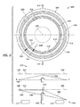
- FIG 2 is an illustration of expanded views 200/202/204 of the wobble plate 106 of Figure 1 according to an embodiment of the disclosure.
- the expanded view 200 shows a top view of the wobble plate 106.
- the expanded view 202 shows a side view of the wobble plate 106 taken along an A-A line, and showing the wobble plate 106 in an unpowered disconnected state.
- the expanded view 204 shows a side view of the wobble plate 106 taken along the A-A line, and showing the wobble plate 106 in a powered state with the wobble plate 106 coupled to the stationary gear 108 and the rotational output plate 120.
- FIG 3 is an illustration of an interface of the wobble plate 106 to the stationary gear 108 and the rotational output plate 120 according to an embodiment of the disclosure.
- one of the electromagnets 130/132/134 such as the electromagnet 134 electromagnetically pulls the first side 208 ( Figure 2 ) of the wobble plate 106 to the stator 104
- the second side 210 ( Figure 2 ) of the wobble plate 106 is pushed against the stationary gear 108 and the rotational output plate 120.
- the inner pericyclic gear 122 of the wobble plate 106 radially meshes with the output plate gear ring 302 of the stationary gear 108 along a plane of the output plate gear ring 302.
- the outer pericyclic gear 124 of the wobble plate 106 radially meshes with the stationary gear ring 304 of the rotational output plate 120 along a plane of the stationary gear ring 304.
- the wobble plate 106 meshes with the stationary gear 108 and the rotational output plate 120 radially inward along a plane that contains the stationary gear 108 and the rotational output plate 120.
- the inner pericyclic gear 122 and the outer pericyclic gear 124 sit at fixed radiuses from the fulcrum 126.
- a radial location of the wobble plate center 206 of gear teeth 220 of the inner pericyclic gear 122 and gear teeth 222 of the outer pericyclic gear 124 of the wobble plate 106 moves radially inward.
- Each gear tooth 220/222 of the inner pericyclic gear 122 and the outer pericyclic gear 124 may comprise a wedge shape 224/226 that is smaller on an inner radius 212/216 than on an outer radius 214/218 of the inner pericyclic gear 122 and the outer pericyclic gear 124.
- the wedge shape 224/226 of each gear tooth 220/222 of the inner pericyclic gear 122 and the outer pericyclic gear 124 is driven radial inward as the wobble plate 106 moves toward the stationary gear 108 and the rotational output plate 120.
- the wedge shape 224/226 may be configured comprising, for example but without limitation, an angle 230/232 in a plane of the wobble plate 106, a surface 306/308 of the wedge shape 224/226 configured at an angle relative to the stationary gear 108 (e.g., when meshed), the surface 306/308 of the wedge shape 224/226 configured at an angle relative to the rotational output plate 120 (e.g., when meshed), the surface 306/308 of the wedge shape 224/226 configured at an angle relative to the wobble plate 106, or other wedge shape configuration.
- Radial motion of the wedge shape 224/226 of each gear tooth 220/222 of the inner pericyclic gear 122 and the outer pericyclic gear 124 aligns the stationary gear 108 and the rotational output plate 120 and applies a radial load to the fulcrum 126.
- Other loads may push the wobble plate 106 away from the stationary gear 108 and the rotational output plate 120 but may be proportional to multiplication of a sine function (sine ⁇ ) of a wedge angle ( ⁇ ) of each gear tooth 220/222 of the inner pericyclic gear 122 and the outer pericyclic gear 124 and a sine function (sine ⁇ ) of a plate angle ( ⁇ ) of the wobble plate 106.
- the wedge angle ( ⁇ ) may comprise, for example but without limitation, about 14 degrees or other suitable angle.
- the plate angle ( ⁇ ) may comprise, for example but without limitation, about 1.6 degrees or other suitable angle.
- a number of gear teeth of the stationary gear 108 is equal to a number of the gear teeth 222 of the outer pericyclic gear 124, and a number of gear teeth of the rotational output plate 120 is equal to a number of the gear teeth 220 of the inner pericyclic gear 122. With such an equal number of teeth, the wobble plate 106 does not rotate relative to the stationary gear 108.
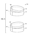
- FIGS 4 and 5 are illustrations of a clock-wise nutation of the wobble plate 106 according to an embodiment of the disclosure.
- Views 402, 404, 406, 502 and 504 show the wobble plate 106 nutating in a clock-wise direction 408 in response to electromagnetic force of the electromagnets 130/132/134 ( Figure 1 ).
- Torque is produced from an angular change of the wobble plate 106.
- a stator pole of the stator 104 Figure 1
- torque of the wobble plate 106 is in a direction that will reduce reluctance.
- a stator magnetic field rotates in advance of the rotor poles, thus constantly "pulling" the wobble plate 106 along.
- FIG 6 is an illustration of a relationship of electromagnetic driving force to a counter clock-wise nutation 614 of the wobble plate 106 generating a virtual ellipse motion according to an embodiment of the disclosure.
- a wobble plate projection 610 comprises an ellipse projection of the wobble plate 106 into an output gear plane 612.
- a magnetic force is applied at a location 602 on a major axis of the wobble plate 106 ( Figure 1 ) at time T0
- a maximum gear mesh occurs at a location 606 on a minor axis of the wobble plate 106 at time T0.
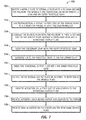
- FIG. 7 is an illustration of an exemplary flowchart showing a process 700 for operating a virtual ellipse electric motor according to an embodiment of the disclosure.
- the various tasks performed in connection with process 700 may be performed mechanically, by software, hardware, firmware, or any combination thereof.
- the following description of process 700 may refer to elements mentioned above in connection with Figures 1-2 .
- portions of the process 700 may be performed by different elements of the virtual ellipse electric motor 100 such as the fulcrum 126, the wobble plate 106, the stationary gear 108, the rotational output plate 120, the stator 104, etc.
- Process 700 may have functions, material, and structures that are similar to the embodiments shown in Figures 1-6 . Therefore common features, functions, and elements may not be redundantly described here.
- Process 700 may begin by nutating a wobble plate such as the wobble plate 106 rotationally coupled to a fulcrum such as the fulcrum 126 around the fulcrum 126, the wobble plate 106 comprising an inner pericyclic gear such as the inner pericyclic gear 122 and an outer pericyclic gear such as the outer pericyclic gear 124 (task 702).
- a wobble plate such as the wobble plate 106 rotationally coupled to a fulcrum such as the fulcrum 126 around the fulcrum 126
- the wobble plate 106 comprising an inner pericyclic gear such as the inner pericyclic gear 122 and an outer pericyclic gear such as the outer pericyclic gear 124 (task 702).
- Process 700 may continue by electromagnetically attracting a first side of the wobble plate 106 such as the first side 208 to a stator such as the stator 104 comprising at least one electromagnet 130/132/134 (task 704).
- Process 700 may continue by leveraging the wobble plate 106 with the fulcrum 126 to press a second side of the wobble plate 106 such as the second side 210 against a stationary gear such as the stationary gear 108 and a rotational output plate such as the rotational output plate 120 (task 706).
- Process 700 may continue by meshing the stationary gear 108 with the outer pericyclic gear 124 (task 708).
- Process 700 may continue by leveraging the outer pericyclic gear 124 to the stationary gear 108 (task 710).
- Process 700 may continue by driving the rotational output plate 120 with the inner pericyclic gear 122 (task 712).
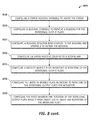
- Process 700 may continue by rotating the rotational output plate 120 in response to nutation of the wobble plate 106 (task 714).
- Process 700 may continue by providing actuation via a first output arm such as the first output arm 116 coupled to the rotational output plate 120 (task 716).
- Process 700 may continue by providing actuation via a second output arm such as the second output arm 128 coupled to the stator 104 (task 718).
- Process 700 may continue by providing dual actuation via the stator 104 and the rotational output plate 120 (task 720).
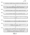
- FIG 8 is an illustration of an exemplary flowchart showing a process 800 for configuring a virtual ellipse electric motor according to an embodiment of the disclosure.
- the various tasks performed in connection with process 800 may be performed mechanically, by software, hardware, firmware, or any combination thereof.
- the following description of process 800 may refer to elements mentioned above in connection with Figures 1-2 .
- portions of the process 800 may be performed by different elements of the virtual ellipse electric motor 100 such as: the fulcrum 126, the wobble plate 106, the stationary gear 108, the rotational output plate 120, the stator 104, etc.
- Process 800 may have functions, material, and structures that are similar to the embodiments shown in Figures 1-6 . Therefore common features, functions, and elements may not be redundantly described here.
- Process 800 may begin by configuring a fulcrum such as the fulcrum 126 to bear a rotating radial dynamic load (task 802).
- Process 800 may continue by rotationally coupling a wobble plate such as the wobble plate 106 comprising an inner pericyclic gear such as the inner pericyclic gear 122 and an outer pericyclic gear such as the outer pericyclic gear 124 to the fulcrum 126 (task 804).
- a wobble plate such as the wobble plate 106 comprising an inner pericyclic gear such as the inner pericyclic gear 122 and an outer pericyclic gear such as the outer pericyclic gear 124 to the fulcrum 126 (task 804).
- Process 800 may continue by configuring the wobble plate 106 to nutate around the fulcrum 126 (task 806).
- Process 800 may continue by meshing a stationary gear such as the stationary gear 108 with the outer pericyclic gear 124 (task 808).
- Process 800 may continue by configuring the stationary gear 108 to provide leverage to the wobble plate 106 (task 810).
- Process 800 may continue by meshing a rotational output plate such as the rotational output plate 120 with the inner pericyclic gear 122 (task 812).
- Process 800 may continue by configuring the rotational output plate 120 to rotate in response to nutation of the wobble plate 106 (task 814).
- Process 800 may continue by configuring a stator such as the stator 104 comprising at least one electromagnet 130/132/134 to electromagnetically attract a first side of the wobble plate 106 such as the first side 208 such that a second side of the wobble plate106 such as the second side 210 is leveraged against the stationary gear 108 and the rotational output plate 120 (task 816).
- a stator such as the stator 104 comprising at least one electromagnet 130/132/134 to electromagnetically attract a first side of the wobble plate 106 such as the first side 208 such that a second side of the wobble plate106 such as the second side 210 is leveraged against the stationary gear 108 and the rotational output plate 120 (task 816).
- Process 800 may continue by configuring a stator housing such as the stator housing 102 operable to house the stator 104 (task 818).
- Process 800 may continue by configuring a bushing such as the bushing 110 operable to provide a bearing for the rotational output plate 120 (task 820).
- Process 800 may continue by configuring a bushing retainer ring such as the bushing retainer ring 118 coupled to the bushing 110 and operable to retain the bushing 110 (task 822).
- a bushing retainer ring such as the bushing retainer ring 118 coupled to the bushing 110 and operable to retain the bushing 110 (task 822).
- Process 800 may continue by configuring an upper housing such as the upper housing 112 coupled to a rocker arm such as the rocker arm 114 (task 824).
- Process 800 may continue by configuring a ratio of wobble plate nutations to rotations of the rotational output plate 120 (task 826).
- Process 800 may continue by configuring the ratio of wobble plate nutations to rotations of the rotational output plate 120 for actuation (task 828).
- Process 800 may continue by configuring the ratio wherein one rotation of the rotational output plate 120 results from about 180 to about 200 nutations of the wobble plate 106 (task 830).
- embodiments of the disclosure provide a high torque low speed electro-mechanical electric motor that performance equal to or greater than hydraulic actuation with power and energy density equal to or greater than hydraulic actuation.
- existing switched reluctance motors do not provide guaranteed starting, controlled starting direction and reversing capability with less than 6 stator poles and 4 rotor poles.
- Embodiments of the disclosure achieves this with 6 stator poles and one virtual rotor pole, and the switched reluctance motors described herein do not have rotor poles, but nonetheless can provide starting, holding, reversing as well as or better than existing motors.
- Embodiments of the disclosure provide an electric motor that need not use expensive rare earth metals, and provides low vibration, and substantially jam free and/or jam tolerant high holding load capability.
- the electric motor can de-couple from an output shaft when in a non-optimal condition or de-powered mechanically, and is electrically robust.
- a group of items linked with the conjunction "and” should not be read as requiring that each and every one of those items be present in the grouping, but rather should be read as “and/or” unless expressly stated otherwise.
- a group of items linked with the conjunction "or” should not be read as requiring mutual exclusivity among that group, but rather should also be read as “and/or” unless expressly stated otherwise.
- operble means able to be used, fit or ready for use or service, usable for a specific purpose, and capable of performing a recited or desired function described herein.
- operble means the system and/or the device is fully functional and calibrated, comprises elements for, and meets applicable operability requirements to perform a recited function when activated.
- operble means the system and/or the circuit is fully functional and calibrated, comprises logic for, and meets applicable operability requirements to perform a recited function when activated.
Landscapes
- Engineering & Computer Science (AREA)
- Power Engineering (AREA)
- Physics & Mathematics (AREA)
- Chemical & Material Sciences (AREA)
- Combustion & Propulsion (AREA)
- Electromagnetism (AREA)
- Connection Of Motors, Electrical Generators, Mechanical Devices, And The Like (AREA)
- Synchronous Machinery (AREA)
- Variable-Direction Aerials And Aerial Arrays (AREA)
- Linear Motors (AREA)
Applications Claiming Priority (1)
| Application Number | Priority Date | Filing Date | Title |
|---|---|---|---|
| US13/849,501 US9281736B2 (en) | 2013-03-23 | 2013-03-23 | Virtual ellipse motor |
Publications (2)
| Publication Number | Publication Date |
|---|---|
| EP2782230A2 true EP2782230A2 (de) | 2014-09-24 |
| EP2782230A3 EP2782230A3 (de) | 2016-10-05 |
Family
ID=50156587
Family Applications (1)
| Application Number | Title | Priority Date | Filing Date |
|---|---|---|---|
| EP14155850.2A Withdrawn EP2782230A3 (de) | 2013-03-23 | 2014-02-19 | Virtueller elliptischer Motor |
Country Status (4)
| Country | Link |
|---|---|
| US (1) | US9281736B2 (de) |
| EP (1) | EP2782230A3 (de) |
| JP (1) | JP6448202B2 (de) |
| CN (1) | CN104065202B (de) |
Cited By (12)
| Publication number | Priority date | Publication date | Assignee | Title |
|---|---|---|---|---|
| EP3032726A1 (de) * | 2014-12-11 | 2016-06-15 | The Boeing Company | Reluktanzmotor mit zweipoligem rotorsystem |
| EP3032727A1 (de) * | 2014-12-11 | 2016-06-15 | The Boeing Company | Reluktanzmotor mit virtuellem rotor |
| US9768664B2 (en) | 2015-05-21 | 2017-09-19 | The Boeing Company | Balanced eccentric gear design and method |
| US10024391B2 (en) | 2016-01-06 | 2018-07-17 | The Boeing Company | Elliptically interfacing gearbox |
| US10203022B2 (en) | 2015-11-04 | 2019-02-12 | The Boeing Company | Elliptically interfacing wobble motion gearing system and method |
| US10215244B2 (en) | 2017-03-02 | 2019-02-26 | The Boeing Company | Elliptically interfacing gear assisted braking system |
| US10267383B2 (en) | 2017-05-03 | 2019-04-23 | The Boeing Company | Self-aligning virtual elliptical drive |
| US10520063B2 (en) | 2017-04-21 | 2019-12-31 | The Boeing Company | Mechanical virtual elliptical drive |
| US10574109B2 (en) | 2016-04-28 | 2020-02-25 | The Boeing Company | Permanent magnet biased virtual elliptical motor |
| US10968969B2 (en) | 2019-03-18 | 2021-04-06 | The Boeing Company | Nutational braking systems and methods |
| US11459098B2 (en) | 2019-11-27 | 2022-10-04 | The Boeing Company | Variable speed transmission and related methods |
| US12531464B2 (en) | 2023-06-12 | 2026-01-20 | Magvad LLC | Magnetic drive apparatus for translating rotational motion to nutational motion |
Families Citing this family (5)
| Publication number | Priority date | Publication date | Assignee | Title |
|---|---|---|---|---|
| US9484828B2 (en) | 2014-03-03 | 2016-11-01 | The Boeing Company | Power frequency converter and associated method |
| CN104617739B (zh) * | 2014-12-23 | 2016-10-05 | 燕山大学 | 机电集成步进电机 |
| US10177641B2 (en) * | 2016-07-26 | 2019-01-08 | The Boeing Company | Stator assembly including stator elements with slotted stator cores for use in an electrical motor |
| US11522425B2 (en) | 2017-10-25 | 2022-12-06 | Indiana University Research And Technology Corporation | Planar high torque electric motor |
| CN110594288B (zh) * | 2019-09-29 | 2024-03-08 | 中国矿业大学 | 一种基于纳米磁性液体的磁控柔性瓦块推力滑动轴承 |
Family Cites Families (21)
| Publication number | Priority date | Publication date | Assignee | Title |
|---|---|---|---|---|
| USRE22549E (en) * | 1944-09-26 | Electric motor | ||
| US2953944A (en) * | 1955-11-16 | 1960-09-27 | Edward V Sundt | Multiple speed reducer |
| JPS4110488Y1 (de) * | 1964-06-30 | 1966-05-18 | ||
| JPS5331241B1 (de) * | 1967-03-31 | 1978-09-01 | ||
| USRE29411E (en) * | 1967-08-30 | 1977-09-20 | Mesur-Matic Electronics Corporation | Harmonic drive for digital step motor |
| US3644764A (en) * | 1967-08-30 | 1972-02-22 | Mesur Matic Electronics Corp | Harmonic drive for digital step motor |
| US3585426A (en) * | 1969-10-06 | 1971-06-15 | Mesur Matic Electronics Corp | Vibration compensation for wobble plate step motors |
| DE2135929B1 (de) * | 1971-07-17 | 1972-12-21 | Saia Ag, Murten (Schweiz) | Vorrichtung zur erzeugung einer drehbewegung mittels mindestens einer pulsierenden antriebskraft |
| JPS591416Y2 (ja) * | 1979-12-19 | 1984-01-14 | アイシン精機株式会社 | ロ−タリソレノイド |
| JPS6439259A (en) * | 1987-07-31 | 1989-02-09 | Tokyo Electric Co Ltd | Stepping motor |
| JP2535503Y2 (ja) | 1991-05-20 | 1997-05-14 | 株式会社ハーモニック・ドライブ・システムズ | カップ型歯車式調和変速装置における外歯および内歯の噛み合わせ構造 |
| US5804898A (en) * | 1995-09-12 | 1998-09-08 | Nihon Riken Co., Ltd. | Electric motor utilizing magnetic energy of permanent magnet |
| JP2002243000A (ja) | 2001-02-19 | 2002-08-28 | Harmonic Drive Syst Ind Co Ltd | 波動歯車減速機を備えたアクチュエータ |
| JP2002339990A (ja) | 2001-05-22 | 2002-11-27 | Harmonic Drive Syst Ind Co Ltd | 軽量ベアリングおよび波動歯車装置 |
| EP1416619B1 (de) | 2001-07-09 | 2011-06-08 | Harmonic Drive Systems Inc. | Hybride elektrische synchronmaschine |
| TWI268036B (en) | 2003-08-04 | 2006-12-01 | Harmonic Drive Systems | Flat hollow type brushless servo motor |
| JP4833028B2 (ja) | 2006-11-01 | 2011-12-07 | 株式会社ハーモニック・ドライブ・システムズ | 波動歯車減速機を備えたアクチュエータ |
| CN200999704Y (zh) * | 2006-11-29 | 2008-01-02 | 邵大斌 | 电动车发电装置 |
| JP4931725B2 (ja) | 2007-07-27 | 2012-05-16 | 株式会社ハーモニック・ドライブ・システムズ | 波動歯車装置 |
| JP5275150B2 (ja) | 2009-06-23 | 2013-08-28 | 株式会社ハーモニック・ドライブ・システムズ | 波動歯車装置 |
| JP5365557B2 (ja) * | 2010-03-17 | 2013-12-11 | オイレス工業株式会社 | スラスト滑り軸受及びこのスラスト滑り軸受とピストンロッドとの組合せ機構 |
-
2013
- 2013-03-23 US US13/849,501 patent/US9281736B2/en not_active Expired - Fee Related
-
2014
- 2014-02-19 EP EP14155850.2A patent/EP2782230A3/de not_active Withdrawn
- 2014-03-19 JP JP2014055719A patent/JP6448202B2/ja not_active Expired - Fee Related
- 2014-03-20 CN CN201410106036.8A patent/CN104065202B/zh not_active Expired - Fee Related
Non-Patent Citations (1)
| Title |
|---|
| None |
Cited By (15)
| Publication number | Priority date | Publication date | Assignee | Title |
|---|---|---|---|---|
| US10164501B2 (en) | 2014-12-11 | 2018-12-25 | The Boeing Company | Reluctance motor with dual-pole rotor system |
| EP3032727A1 (de) * | 2014-12-11 | 2016-06-15 | The Boeing Company | Reluktanzmotor mit virtuellem rotor |
| US9929623B2 (en) | 2014-12-11 | 2018-03-27 | The Boeing Company | Reluctance motor with virtual rotor |
| EP3032726A1 (de) * | 2014-12-11 | 2016-06-15 | The Boeing Company | Reluktanzmotor mit zweipoligem rotorsystem |
| US9768664B2 (en) | 2015-05-21 | 2017-09-19 | The Boeing Company | Balanced eccentric gear design and method |
| US10203022B2 (en) | 2015-11-04 | 2019-02-12 | The Boeing Company | Elliptically interfacing wobble motion gearing system and method |
| US10024391B2 (en) | 2016-01-06 | 2018-07-17 | The Boeing Company | Elliptically interfacing gearbox |
| US10574109B2 (en) | 2016-04-28 | 2020-02-25 | The Boeing Company | Permanent magnet biased virtual elliptical motor |
| US10215244B2 (en) | 2017-03-02 | 2019-02-26 | The Boeing Company | Elliptically interfacing gear assisted braking system |
| US10520063B2 (en) | 2017-04-21 | 2019-12-31 | The Boeing Company | Mechanical virtual elliptical drive |
| US10267383B2 (en) | 2017-05-03 | 2019-04-23 | The Boeing Company | Self-aligning virtual elliptical drive |
| US10612626B2 (en) | 2017-05-03 | 2020-04-07 | The Boeing Company | Self-aligning virtual elliptical drive |
| US10968969B2 (en) | 2019-03-18 | 2021-04-06 | The Boeing Company | Nutational braking systems and methods |
| US11459098B2 (en) | 2019-11-27 | 2022-10-04 | The Boeing Company | Variable speed transmission and related methods |
| US12531464B2 (en) | 2023-06-12 | 2026-01-20 | Magvad LLC | Magnetic drive apparatus for translating rotational motion to nutational motion |
Also Published As
| Publication number | Publication date |
|---|---|
| CN104065202A (zh) | 2014-09-24 |
| JP6448202B2 (ja) | 2019-01-09 |
| JP2014187867A (ja) | 2014-10-02 |
| US20140285072A1 (en) | 2014-09-25 |
| US9281736B2 (en) | 2016-03-08 |
| EP2782230A3 (de) | 2016-10-05 |
| CN104065202B (zh) | 2018-11-16 |
Similar Documents
| Publication | Publication Date | Title |
|---|---|---|
| US9281736B2 (en) | Virtual ellipse motor | |
| EP2686942B1 (de) | Elektromotor mt planetarem zug und druck | |
| EP2081276A1 (de) | Elektromagnetische Vorrichtung mit umschaltbarem Generator- oder Motorbetrieb | |
| EP3032727B1 (de) | Reluktanzmotor mit virtuellem rotor | |
| US7777385B2 (en) | Compact, electromagnetically braked actuator assembly | |
| US20090009011A1 (en) | Motor using magnetic normal force | |
| KR101577621B1 (ko) | 모터 중심축에 위성기어를 장치하여 좌우 양축 상호 역회전하는 회전축이 두개인 모터장치 | |
| KR102275578B1 (ko) | 자성 유체 모터 | |
| US10164501B2 (en) | Reluctance motor with dual-pole rotor system | |
| CN113615067A (zh) | 利用多重多相线圈磁场锁定的电磁机械 | |
| US20140375151A1 (en) | Stepper motor with integrated brake and drive circuit | |
| EP2528207A1 (de) | Bürstenlose elektrische Maschine | |
| RU2538478C1 (ru) | Мотор-редуктор с интегрированным прецессирующим зубчатым колесом (варианты) | |
| EP3017529B1 (de) | Reduzierung der lagerkräfte bei einer elektrischen maschine | |
| CN113300556A (zh) | 双自由度电磁机器 | |
| CN101621224B (zh) | 同轴内外线圈电动机 | |
| CN102723806A (zh) | 行星电机 | |
| US9035530B2 (en) | Energy converting device having an eccentric rotor | |
| GB2453027A (en) | Motor using magnetic normal force | |
| Morozov et al. | Peculiarities of the control actuator development on the basis of combined electromechanical modules | |
| WO2026093778A1 (en) | Multipurpose generator or electric motor for applying different voltages, powers, speeds, and torques with expandability features in both phases | |
| RU2543522C2 (ru) | Мехатронное устройство | |
| CN102371589A (zh) | 具有断电自锁功能的磁控式机器臂关节制动器 | |
| RU113549U1 (ru) | Планетарный привод | |
| Jung et al. | A study on design and manufacturing of a micro brushless DC motor |
Legal Events
| Date | Code | Title | Description |
|---|---|---|---|
| PUAI | Public reference made under article 153(3) epc to a published international application that has entered the european phase |
Free format text: ORIGINAL CODE: 0009012 |
|
| 17P | Request for examination filed |
Effective date: 20140219 |
|
| AK | Designated contracting states |
Kind code of ref document: A2 Designated state(s): AL AT BE BG CH CY CZ DE DK EE ES FI FR GB GR HR HU IE IS IT LI LT LU LV MC MK MT NL NO PL PT RO RS SE SI SK SM TR |
|
| AX | Request for extension of the european patent |
Extension state: BA ME |
|
| PUAL | Search report despatched |
Free format text: ORIGINAL CODE: 0009013 |
|
| RIC1 | Information provided on ipc code assigned before grant |
Ipc: H02K 41/06 20060101AFI20160824BHEP Ipc: F16C 35/02 20060101ALN20160824BHEP Ipc: F16C 17/04 20060101ALN20160824BHEP |
|
| AK | Designated contracting states |
Kind code of ref document: A3 Designated state(s): AL AT BE BG CH CY CZ DE DK EE ES FI FR GB GR HR HU IE IS IT LI LT LU LV MC MK MT NL NO PL PT RO RS SE SI SK SM TR |
|
| AX | Request for extension of the european patent |
Extension state: BA ME |
|
| STAA | Information on the status of an ep patent application or granted ep patent |
Free format text: STATUS: EXAMINATION IS IN PROGRESS |
|
| 17Q | First examination report despatched |
Effective date: 20170627 |
|
| STAA | Information on the status of an ep patent application or granted ep patent |
Free format text: STATUS: THE APPLICATION IS DEEMED TO BE WITHDRAWN |
|
| 18D | Application deemed to be withdrawn |
Effective date: 20200311 |