EP2781206A1 - Zweiteiliger Kniespacer mit Aussparungen - Google Patents
Zweiteiliger Kniespacer mit Aussparungen Download PDFInfo
- Publication number
- EP2781206A1 EP2781206A1 EP14155453.5A EP14155453A EP2781206A1 EP 2781206 A1 EP2781206 A1 EP 2781206A1 EP 14155453 A EP14155453 A EP 14155453A EP 2781206 A1 EP2781206 A1 EP 2781206A1
- Authority
- EP
- European Patent Office
- Prior art keywords
- recesses
- component
- tibial component
- knee spacer
- femoral component
- Prior art date
- Legal status (The legal status is an assumption and is not a legal conclusion. Google has not performed a legal analysis and makes no representation as to the accuracy of the status listed.)
- Granted
Links
Images



Classifications
-
- A—HUMAN NECESSITIES
- A61—MEDICAL OR VETERINARY SCIENCE; HYGIENE
- A61F—FILTERS IMPLANTABLE INTO BLOOD VESSELS; PROSTHESES; DEVICES PROVIDING PATENCY TO, OR PREVENTING COLLAPSING OF, TUBULAR STRUCTURES OF THE BODY, e.g. STENTS; ORTHOPAEDIC, NURSING OR CONTRACEPTIVE DEVICES; FOMENTATION; TREATMENT OR PROTECTION OF EYES OR EARS; BANDAGES, DRESSINGS OR ABSORBENT PADS; FIRST-AID KITS
- A61F2/00—Filters implantable into blood vessels; Prostheses, i.e. artificial substitutes or replacements for parts of the body; Appliances for connecting them with the body; Devices providing patency to, or preventing collapsing of, tubular structures of the body, e.g. stents
- A61F2/02—Prostheses implantable into the body
- A61F2/30—Joints
- A61F2/38—Joints for elbows or knees
- A61F2/3836—Special connection between upper and lower leg, e.g. constrained
- A61F2/384—Special connection between upper and lower leg, e.g. constrained hinged, i.e. with transverse axle restricting the movement
- A61F2/385—Special connection between upper and lower leg, e.g. constrained hinged, i.e. with transverse axle restricting the movement also provided with condylar bearing surfaces
-
- A—HUMAN NECESSITIES
- A61—MEDICAL OR VETERINARY SCIENCE; HYGIENE
- A61F—FILTERS IMPLANTABLE INTO BLOOD VESSELS; PROSTHESES; DEVICES PROVIDING PATENCY TO, OR PREVENTING COLLAPSING OF, TUBULAR STRUCTURES OF THE BODY, e.g. STENTS; ORTHOPAEDIC, NURSING OR CONTRACEPTIVE DEVICES; FOMENTATION; TREATMENT OR PROTECTION OF EYES OR EARS; BANDAGES, DRESSINGS OR ABSORBENT PADS; FIRST-AID KITS
- A61F2/00—Filters implantable into blood vessels; Prostheses, i.e. artificial substitutes or replacements for parts of the body; Appliances for connecting them with the body; Devices providing patency to, or preventing collapsing of, tubular structures of the body, e.g. stents
- A61F2/02—Prostheses implantable into the body
- A61F2/30—Joints
- A61F2/38—Joints for elbows or knees
-
- A—HUMAN NECESSITIES
- A61—MEDICAL OR VETERINARY SCIENCE; HYGIENE
- A61F—FILTERS IMPLANTABLE INTO BLOOD VESSELS; PROSTHESES; DEVICES PROVIDING PATENCY TO, OR PREVENTING COLLAPSING OF, TUBULAR STRUCTURES OF THE BODY, e.g. STENTS; ORTHOPAEDIC, NURSING OR CONTRACEPTIVE DEVICES; FOMENTATION; TREATMENT OR PROTECTION OF EYES OR EARS; BANDAGES, DRESSINGS OR ABSORBENT PADS; FIRST-AID KITS
- A61F2/00—Filters implantable into blood vessels; Prostheses, i.e. artificial substitutes or replacements for parts of the body; Appliances for connecting them with the body; Devices providing patency to, or preventing collapsing of, tubular structures of the body, e.g. stents
- A61F2/02—Prostheses implantable into the body
- A61F2/30—Joints
- A61F2/38—Joints for elbows or knees
- A61F2/3859—Femoral components
-
- A—HUMAN NECESSITIES
- A61—MEDICAL OR VETERINARY SCIENCE; HYGIENE
- A61F—FILTERS IMPLANTABLE INTO BLOOD VESSELS; PROSTHESES; DEVICES PROVIDING PATENCY TO, OR PREVENTING COLLAPSING OF, TUBULAR STRUCTURES OF THE BODY, e.g. STENTS; ORTHOPAEDIC, NURSING OR CONTRACEPTIVE DEVICES; FOMENTATION; TREATMENT OR PROTECTION OF EYES OR EARS; BANDAGES, DRESSINGS OR ABSORBENT PADS; FIRST-AID KITS
- A61F2/00—Filters implantable into blood vessels; Prostheses, i.e. artificial substitutes or replacements for parts of the body; Appliances for connecting them with the body; Devices providing patency to, or preventing collapsing of, tubular structures of the body, e.g. stents
- A61F2/02—Prostheses implantable into the body
- A61F2/30—Joints
- A61F2/38—Joints for elbows or knees
- A61F2/389—Tibial components
-
- A—HUMAN NECESSITIES
- A61—MEDICAL OR VETERINARY SCIENCE; HYGIENE
- A61F—FILTERS IMPLANTABLE INTO BLOOD VESSELS; PROSTHESES; DEVICES PROVIDING PATENCY TO, OR PREVENTING COLLAPSING OF, TUBULAR STRUCTURES OF THE BODY, e.g. STENTS; ORTHOPAEDIC, NURSING OR CONTRACEPTIVE DEVICES; FOMENTATION; TREATMENT OR PROTECTION OF EYES OR EARS; BANDAGES, DRESSINGS OR ABSORBENT PADS; FIRST-AID KITS
- A61F2/00—Filters implantable into blood vessels; Prostheses, i.e. artificial substitutes or replacements for parts of the body; Appliances for connecting them with the body; Devices providing patency to, or preventing collapsing of, tubular structures of the body, e.g. stents
- A61F2/02—Prostheses implantable into the body
- A61F2/30—Joints
- A61F2002/30001—Additional features of subject-matter classified in A61F2/28, A61F2/30 and subgroups thereof
- A61F2002/30108—Shapes
- A61F2002/30199—Three-dimensional shapes
- A61F2002/30224—Three-dimensional shapes cylindrical
-
- A—HUMAN NECESSITIES
- A61—MEDICAL OR VETERINARY SCIENCE; HYGIENE
- A61F—FILTERS IMPLANTABLE INTO BLOOD VESSELS; PROSTHESES; DEVICES PROVIDING PATENCY TO, OR PREVENTING COLLAPSING OF, TUBULAR STRUCTURES OF THE BODY, e.g. STENTS; ORTHOPAEDIC, NURSING OR CONTRACEPTIVE DEVICES; FOMENTATION; TREATMENT OR PROTECTION OF EYES OR EARS; BANDAGES, DRESSINGS OR ABSORBENT PADS; FIRST-AID KITS
- A61F2/00—Filters implantable into blood vessels; Prostheses, i.e. artificial substitutes or replacements for parts of the body; Appliances for connecting them with the body; Devices providing patency to, or preventing collapsing of, tubular structures of the body, e.g. stents
- A61F2/02—Prostheses implantable into the body
- A61F2/30—Joints
- A61F2002/30001—Additional features of subject-matter classified in A61F2/28, A61F2/30 and subgroups thereof
- A61F2002/30667—Features concerning an interaction with the environment or a particular use of the prosthesis
- A61F2002/30672—Features concerning an interaction with the environment or a particular use of the prosthesis temporary
-
- A—HUMAN NECESSITIES
- A61—MEDICAL OR VETERINARY SCIENCE; HYGIENE
- A61F—FILTERS IMPLANTABLE INTO BLOOD VESSELS; PROSTHESES; DEVICES PROVIDING PATENCY TO, OR PREVENTING COLLAPSING OF, TUBULAR STRUCTURES OF THE BODY, e.g. STENTS; ORTHOPAEDIC, NURSING OR CONTRACEPTIVE DEVICES; FOMENTATION; TREATMENT OR PROTECTION OF EYES OR EARS; BANDAGES, DRESSINGS OR ABSORBENT PADS; FIRST-AID KITS
- A61F2/00—Filters implantable into blood vessels; Prostheses, i.e. artificial substitutes or replacements for parts of the body; Appliances for connecting them with the body; Devices providing patency to, or preventing collapsing of, tubular structures of the body, e.g. stents
- A61F2/02—Prostheses implantable into the body
- A61F2/30—Joints
- A61F2002/30001—Additional features of subject-matter classified in A61F2/28, A61F2/30 and subgroups thereof
- A61F2002/30667—Features concerning an interaction with the environment or a particular use of the prosthesis
- A61F2002/30677—Means for introducing or releasing pharmaceutical products, e.g. antibiotics, into the body
-
- A—HUMAN NECESSITIES
- A61—MEDICAL OR VETERINARY SCIENCE; HYGIENE
- A61F—FILTERS IMPLANTABLE INTO BLOOD VESSELS; PROSTHESES; DEVICES PROVIDING PATENCY TO, OR PREVENTING COLLAPSING OF, TUBULAR STRUCTURES OF THE BODY, e.g. STENTS; ORTHOPAEDIC, NURSING OR CONTRACEPTIVE DEVICES; FOMENTATION; TREATMENT OR PROTECTION OF EYES OR EARS; BANDAGES, DRESSINGS OR ABSORBENT PADS; FIRST-AID KITS
- A61F2/00—Filters implantable into blood vessels; Prostheses, i.e. artificial substitutes or replacements for parts of the body; Appliances for connecting them with the body; Devices providing patency to, or preventing collapsing of, tubular structures of the body, e.g. stents
- A61F2/02—Prostheses implantable into the body
- A61F2/30—Joints
- A61F2/30767—Special external or bone-contacting surface, e.g. coating for improving bone ingrowth
- A61F2/30771—Special external or bone-contacting surface, e.g. coating for improving bone ingrowth applied in original prostheses, e.g. holes or grooves
- A61F2002/30878—Special external or bone-contacting surface, e.g. coating for improving bone ingrowth applied in original prostheses, e.g. holes or grooves with non-sharp protrusions, for instance contacting the bone for anchoring, e.g. keels, pegs, pins, posts, shanks, stems, struts
-
- A—HUMAN NECESSITIES
- A61—MEDICAL OR VETERINARY SCIENCE; HYGIENE
- A61F—FILTERS IMPLANTABLE INTO BLOOD VESSELS; PROSTHESES; DEVICES PROVIDING PATENCY TO, OR PREVENTING COLLAPSING OF, TUBULAR STRUCTURES OF THE BODY, e.g. STENTS; ORTHOPAEDIC, NURSING OR CONTRACEPTIVE DEVICES; FOMENTATION; TREATMENT OR PROTECTION OF EYES OR EARS; BANDAGES, DRESSINGS OR ABSORBENT PADS; FIRST-AID KITS
- A61F2/00—Filters implantable into blood vessels; Prostheses, i.e. artificial substitutes or replacements for parts of the body; Appliances for connecting them with the body; Devices providing patency to, or preventing collapsing of, tubular structures of the body, e.g. stents
- A61F2/02—Prostheses implantable into the body
- A61F2/30—Joints
- A61F2/46—Special tools for implanting artificial joints
- A61F2002/4631—Special tools for implanting artificial joints the prosthesis being specially adapted for being cemented
-
- A—HUMAN NECESSITIES
- A61—MEDICAL OR VETERINARY SCIENCE; HYGIENE
- A61F—FILTERS IMPLANTABLE INTO BLOOD VESSELS; PROSTHESES; DEVICES PROVIDING PATENCY TO, OR PREVENTING COLLAPSING OF, TUBULAR STRUCTURES OF THE BODY, e.g. STENTS; ORTHOPAEDIC, NURSING OR CONTRACEPTIVE DEVICES; FOMENTATION; TREATMENT OR PROTECTION OF EYES OR EARS; BANDAGES, DRESSINGS OR ABSORBENT PADS; FIRST-AID KITS
- A61F2240/00—Manufacturing or designing of prostheses classified in groups A61F2/00 - A61F2/26 or A61F2/82 or A61F9/00 or A61F11/00 or subgroups thereof
- A61F2240/001—Designing or manufacturing processes
-
- A—HUMAN NECESSITIES
- A61—MEDICAL OR VETERINARY SCIENCE; HYGIENE
- A61F—FILTERS IMPLANTABLE INTO BLOOD VESSELS; PROSTHESES; DEVICES PROVIDING PATENCY TO, OR PREVENTING COLLAPSING OF, TUBULAR STRUCTURES OF THE BODY, e.g. STENTS; ORTHOPAEDIC, NURSING OR CONTRACEPTIVE DEVICES; FOMENTATION; TREATMENT OR PROTECTION OF EYES OR EARS; BANDAGES, DRESSINGS OR ABSORBENT PADS; FIRST-AID KITS
- A61F2310/00—Prostheses classified in A61F2/28 or A61F2/30 - A61F2/44 being constructed from or coated with a particular material
- A61F2310/00005—The prosthesis being constructed from a particular material
- A61F2310/00353—Bone cement, e.g. polymethylmethacrylate or PMMA
-
- Y—GENERAL TAGGING OF NEW TECHNOLOGICAL DEVELOPMENTS; GENERAL TAGGING OF CROSS-SECTIONAL TECHNOLOGIES SPANNING OVER SEVERAL SECTIONS OF THE IPC; TECHNICAL SUBJECTS COVERED BY FORMER USPC CROSS-REFERENCE ART COLLECTIONS [XRACs] AND DIGESTS
- Y10—TECHNICAL SUBJECTS COVERED BY FORMER USPC
- Y10T—TECHNICAL SUBJECTS COVERED BY FORMER US CLASSIFICATION
- Y10T29/00—Metal working
- Y10T29/49—Method of mechanical manufacture
Definitions
- the invention relates to a knee spacer for temporary replacement of an artificial knee joint, wherein the knee spacer has a tibial component and a femoral component as a separate and, when inserted in the patient state, against each other movable components.
- the invention also relates to a method for producing a knee spacer and the use of such a knee spacer.
- the invention thus relates to a two-part knee spacer or a two-part knee spacer system, which is used as a temporary placeholder in the context of two-stage septic revisions of knee joint endoprostheses.
- Joint endoprostheses currently have a life of several years, for example in cemented hip joint prostheses on average greater than ten to fifteen years. However, there are unwanted loosening of the joint endoprostheses, which occur before reaching the usual service life. A distinction is made between septic and aseptic loosening. So far, no microbial germs can be detected in aseptic loosening. The causes of aseptic loosening can be manifold. Often, aseptic loosening is due to abrasion on the sliding surfaces of the joint endoprostheses.
- septic loosening In septic loosening, the loosening process is caused by microbial germs. One differentiates thereby depending on the temporal occurrence early and late infections. Septic loosening is a very serious condition for the patient, which is also associated with very high cost of treatment. Both aseptic and septic loosening are usually revised. There are one-time and two-stage revisions. For septic loosening very often two-stage revisions are made.
- the infected joint endoprosthesis is removed in a first operation (OP), there is a debridement (removal of the infected tissue) and then a temporary placeholder, a so-called spacer, is used.
- This spacer fills the space of the previously revised endoprosthesis for a few weeks until the present infection subsides.
- This placeholder function is very important to effectively prevent muscular atrophy during this time and to stabilize the resection situation.
- Articulating spacers simulate joint function and allow some mobility of the affected limbs. It is thereby possible to mobilize the patients early. Articulating spacers are therefore currently very popular. The spacer is removed in a second OP, it is debrided again and then a cemented or also cementless revision joint endoprosthesis is implanted.
- McPherson's idea is that spacers can only be made from bone cement ( McPherson EJ, Lewonowski K, Dorr LD (1995), “Techniques in arthroplasty.”, J. Arthroplasty 10: 87-89 ).
- Knee spacers are generally bipartite and consist of a tibial component and a femoral component.
- a typical spacer or a typical spacer system is in the EP 1 274 374 A1 disclosed.
- both the tibial component and the femoral component must be anchored to the proximal tibia and the distal femur with polymethyl methacrylate bone cement.
- the polymethyl methacrylate bone cement adheres to the surface of the spacer components.
- the surface of the spacer components which generally consist of hardened antibiotic-doped polymethyl methacrylate bone cement, is more or less dissolved by the methyl methacrylate of the polymethyl methacrylate bone cement. This leads to the bond with the curing polymethyl methacrylate bone cement. This is essentially due to the adhesion of the polymethyl methacrylate bone cement to the surface of the spacer components.
- the problem is that during the implantation, which may last between two weeks to a maximum of six months, depending on the treatment concept, due to the walking motion of the patients, the spacer components can be detached by torsional forces from the polymethyl methacrylate bone cement used for anchoring.
- the object of the invention is therefore to overcome the disadvantages of the prior art.
- a more stable articulating knee spacer is to be provided, with which robust connections to the femur and tibia can be produced.
- the spacer should be particularly easy to move and remain stable even with frequent movement. At the same time, the spacer should be inexpensive to manufacture.
- a knee spacer for temporary replacement of an artificial knee joint
- the knee spacer has a tibial component and a femoral component as a separate and, when inserted in the patient state, against each other movable components and the tibial component and the femoral component each have at least one tread, via which the tibial component and the femoral component for the condition used in the patient are movable against each other
- the tibial component has an anchoring surface, which is arranged opposite the tread surface and which is provided for connecting the tibial component with the tibia by means of a bone cement and the femoral component Anchoring surface, which is arranged opposite the tread side and which is provided for connecting the femoral component to the femur
- the tibial component and the femoral component in each case at least has two recesses extending from the anchoring surface in the direction of the tread side to the tread side, wherein the openings of the recesses of
- the state used in the patient means the arrangement in which the components of the knee spacer are cemented in the knee of the patient or are to be cemented in order to form a functional, that is to say movable, temporary implant.
- the recesses are arranged on the edge in the tibial component and the femoral component.
- At least two of the recesses are arranged opposite one another in such a way that, in the state of the components inserted in the patient, stems formed in the recesses by the bone cement engage the components in such a way that portions of the components, Preferably, central areas of the components are arranged between the foothills.
- Tapping into the pliers means that opposing forces can act on the inner walls of two recesses.
- the forces preferably act continuously throughout the components. With these forces, a particularly stable attachment of the components and a variable power absorption while walking are achieved.
- the spurs are formed by the bone cement, which fixes the components to the bone. The extensions of the bone cement thereby form a U-shaped engagement in two recesses.
- the recesses do not extend into the tread.
- projections for anchoring the bone cement are arranged in the recesses.
- the tibial component and / or the femoral component is or are asymmetrical to a plane in the inserted state, which is parallel to the sagittal plane of the patient, preferably by the arrangement and / or shape of a recess for receiving of the patient's cruciate ligament is or are asymmetrical and / or is asymmetric due to the arrangement and / or shape of the recesses.
- the recesses may be symmetrical to the plane parallel to the patient's sagittal plane when inserted.
- the recesses over which the torsional forces are to be transmitted to the hardened bone cement are not symmetrical to the plane parallel to the plane when inserted Sagittal plane of the patient is.
- recesses are designed as cylinders, truncated cones and / or as multi-sided prisms, wherein at least one end face of the cylinders, truncated cones and / or prisms is open to the anchoring surface, in particular both end faces of the cylinders, truncated cones and / or prisms for Anchoring surface and the tread side are open, and wherein preferably the lateral surfaces of the cylinder, the truncated cones and / or prisms are closed in the longitudinal direction or simply broken in the axial direction.
- symmetries are well suited for absorbing the forces of walking and are easy to manufacture.
- the symmetry of the recesses may optionally be broken by the protrusions for anchoring the bone cement according to the invention.
- the invention also proposes that at least one first guide element is arranged on the tread surface of the tibial component and at least one second guide element is arranged on the tread side of the femoral component, wherein the guide elements, in the state used in the patient, by positive locking during rotational movement of the two components against each other a displacement of the femoral component towards the tibial component in the direction of a plane which is parallel to the sagittal plane, prevent.
- the tibial component and the femoral component are constructed with at least one plastic and / or metal, preferably made of plastic and / or metal, more preferably from polymethyl methacrylate, most preferably from antibiotics doped cured polymethyl methacrylate bone cement ,
- the tibial component has a shank that extends from a central position of the anchoring surface at an angle between 85 ° and 90 ° from the anchoring surface, preferably perpendicularly extending from the anchoring surface, and the shank for anchoring in one Recess is provided in the tibia, wherein the shaft is preferably at least partially converging from the anchoring surface.
- the shaft is used for anchoring in the tibia. This achieves a particularly stable connection to the tibia.
- a plurality of spacers are arranged on the anchoring surface of at least one of the components, preferably both components, wherein the spacers are preferably converging at least partially from the anchoring surface, and particularly preferably the shank is at least four times as high as the spacers the anchoring surface of the tibial component.
- the spacers serve to ensure that a sufficient amount and a sufficient layer thickness of the bone cement for the connection of the components remain with the bone, thus creating a stable connection of the components with the bone.
- the objects of the invention are also achieved by a method for producing a knee spacer in which the tibial component and the femoral component are produced as separate parts and at least two recesses are formed in the tibial component and at least two recesses are formed in the femoral component.
- the recesses cause a stabilization of the structure of the knee with the knee spacer during walking movements of the patient.
- the invention is based on the surprising finding that it is possible by recesses in the two components of the knee spacer that the bone cement can harden in these recesses and thus produces a mechanically stable connection between the parts of the knee spacer and the connecting bone cement, which is capable of doing so is to absorb the torsional forces occurring while walking without the bone cement separating from the components of the knee spacer.
- the invention thus provides a two-part knee spacer in which an undesired torsion of the tibial component and also of the femoral component can be largely ruled out during the implantation time compared with the polymethyl methacrylate bone cement used for temporary anchoring.
- the torsional forces are absorbed well and over a large area by the bone cement foothills produced in the recesses, so that at no point the connection between the knee spacer or the components of the knee spacer and the bone cement force or torque peaks arise, leading to a destruction of the compound or to a breaking of the Bone cement would result.
- the tibial component and the femoral component each have at least two recesses connecting the distal and the proximal surfaces of the respective components, so that the polymethyl methacrylate bone cement used for fixation can engage in the recesses, so that it can a positive connection between the polymethyl methacrylate bone cement and the tibial component and a positive connection between the polymethyl methacrylate bone cement and the femoral component comes.
- the recesses are not located within the running surfaces or sliding surfaces of the tibial component and the femoral component.
- the tibial component to the femoral component is arranged that the running pairing or sliding pair of the at least one proximal tread of the tibial component with the at least one distal tread of the femoral component does not extend over recesses of the tibial component and the femoral component.
- the knee spacer according to the invention is used as a temporary placeholder in the context of two-stage septic revisions of knee joint endoprostheses.
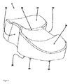
- FIG. 1 shows a schematic perspective view of a knee spacer according to the invention.
- the knee spacer has a femoral component 1 (in FIG. 1 above) and a tibial component 2 (in FIG. 1 below).
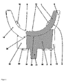
- FIG. 2 shows a schematic perspective view of the tibial component 2 of the knee spacer according to the invention
- FIG. 3 shows a schematic side view of the femoral component 1 of the knee spacer according to the invention FIG. 1 each individually and separately.
- FIG. 4 also shows a schematic cross-sectional view of the knee spacer according to the invention FIG. 1 , wherein the cut surfaces are shown hatched.
- the femoral component 1 has a convex underside as a running surface 4.
- the tread 4 opposite side is accordingly curved inward and forms an anchoring surface 6 for attachment of the femoral component 1 to a femur (thigh bone - not shown).
- a recess 8 is also provided as a guide element.
- the tread 4 is cylindrically shaped.
- the tread 4 and the recess form a common body portion of the rotary body, so that the tread surface is rotatable and can slide on a suitable rotationally symmetrical inner curvature. Alternatively, but less preferably, the tread surface can roll on a flat or less curved inside curvature.
- the spacers 10 are provided on the anchoring surface 6 to ensure that there is a minimum amount and a minimum thickness of bone cement between the femoral component 1 and the femur when the knee spacer is inserted in a patient.
- the spacers 10 extend parallel to each other away from the anchoring surface 6. The direction in which the spacers 10 extend away from the anchoring surface 6 corresponds to the position of the femur when the femoral component 1 is properly inserted in the patient.
- the spacers 10 have rectangular bases with rounded corners.
- the two middle spacers 10 form straight general cylinders with rounded rectangular bases, while the four other spacers 10 are inclined general cylinders with rounded rectangular bases.
- two recesses 12 extend from the anchoring surface 6 to the opposite side of the tread.
- the recesses 12 have the geometry of a cylinder jacket segment.
- the cylinder jacket segment of the recesses 12 comprises approximately 45 ° of a complete cylinder jacket.
- the cylinder jacket segments of the recesses 12 have a region arranged parallel to one another, between which an outer part of the femoral component 1 is arranged.
- extensions of the hardened bone cement extend into the recesses 12. These extensions take the outer portion of the femoral component 1 in the forceps and thus ensure a stable attachment of the femoral component 1 to the femur, which is able to absorb the forces, torsions and torques occurring during walking, without damaging the connection of the femoral component 1 to the femur.
- a wide slot-shaped recess 14 is provided, which is used for anchoring one as well as the other recesses 12, but which also serves to accommodate the cruciate ligaments of the patient.
- the recess 14 and the recesses 12 face each other in such a way that causes a stable attachment through the extensions of the bone cement and so the central areas of the femoral component 1 are taken in the pliers.
- the tibial component 2 (below) has at the top (in the FIGS. 1 . 2 and 4 Above) a tread 24, which has the same curvature as the running surface 4 of the femoral component 1 but as an inner curvature.
- the treads 4, 24 fit so positively into one another.
- the underside of the tibial component 2 is planar and forms the anchoring surface 26 of the tibial component 2, with which the tibial component 2 can be attached to the tibia (the tibia - not shown).
- the upper side of the tibial component 2 has an elevation 28 as a guide element.
- the running surface 24 and the elevation 28 form a common body region of the rotary body 24, 28 which fits into the body region 4, 8 of the femur component 1.
- the recess 8 and the elevation 28 extend thereto along the circumference of the rotary body shell segments.
- a shaft 31 is provided, which also extends perpendicularly from the anchoring surface 26 downwardly and also converges slightly conically downwards. The shaft 31 is inserted into a corresponding cavity in the tibia and serves to stabilize the knee spacer.
- Both the shaft 31 and the spacers 30 are truncated cones with rounded rectangular bases and rounded edges.
- recesses 32 On two sides of the tibial component 2 there are two recesses 32 on the edge, which serve the same purpose as the recesses 12, 14 of the femoral component 1 (see above).
- recess 32 pointing to the right forms a cylinder shell segment with approximately half the circumference (ie 180 °) and, like the recess 14, additionally serves to accommodate the cruciate ligament when the knee spacer is inserted in the patient.
- FIG. 2 to front left aligned and also in FIG. 1 The recess 32 to be seen runs conically upwards in the direction of the femoral component 1 and therefore forms a truncated cone lateral surface segment.
- the recess 32 of the tibial component 2 forming the truncated cone lateral surface and two of the spacers 30 are not arranged symmetrically with respect to the middle ridge of the elevation 28 or to the plane of the knee spacer parallel to the sagittal plane in order to be able to derive the forces and torques occurring during walking in accordance with the walking movement.
- the survey 28 is thus only approximately between the recesses 32 of the tibial component. 2
- the femoral component 1 and the tibial component 2 are present as separate parts and are made of a suitable plastic.
- the two components 1, 2 are preferably manufactured from a hardened polymethyl methacrylate bone cement doped with antibiotics. With the same bone cement, the components 1, 2 are also used in the patient and attached to the tibia or the femur.
- FIG. 5 shows a schematic cross-sectional view of an alternative tibial component of a knee spacer according to the invention.
- the tibial component shown has a flat tread 44 as the top (in FIG. 5 above) and a parallel planar anchoring surface 46 as a bottom (in FIG. 5 below).
- a plurality of spacers 50 are provided, which serve the same purpose as the spacers 10, 30 after the FIGS. 1 to 4 should meet.
- a shaft 51 is also provided at a central position of the anchoring surface 46 of the tibial component, which serves the same purpose as the shaft 31 of the tibial component 2 after the FIGS. 1 and 2 ,
- the tibial component in the section shown cut two recesses 52, which serve the same purpose as the recesses 32 of the tibial component 2 after the FIGS. 1 . 2 and 4 ,
- projections 54 are provided, which can be surrounded by the anchoring surface 46 with bone cement and thus lead to an even more stable anchoring of the tibial component of the tibia.
- the principle according to the invention can be easily transferred to the recesses of a femoral component.
- rounded corners and edges are preferred for knee spacers.
Landscapes
- Health & Medical Sciences (AREA)
- Orthopedic Medicine & Surgery (AREA)
- Physical Education & Sports Medicine (AREA)
- Cardiology (AREA)
- Oral & Maxillofacial Surgery (AREA)
- Transplantation (AREA)
- Engineering & Computer Science (AREA)
- Biomedical Technology (AREA)
- Heart & Thoracic Surgery (AREA)
- Vascular Medicine (AREA)
- Life Sciences & Earth Sciences (AREA)
- Animal Behavior & Ethology (AREA)
- General Health & Medical Sciences (AREA)
- Public Health (AREA)
- Veterinary Medicine (AREA)
- Prostheses (AREA)
Abstract
Description
- Die Erfindung betrifft einen Kniespacer zum zeitweisen Ersetzen eines künstlichen Kniegelenks, wobei der Kniespacer eine Tibiakomponente und eine Femurkomponente als separate und, im beim Patienten eingesetzten Zustand, gegeneinander bewegliche Komponenten aufweist. Die Erfindung betrifft auch ein Verfahren zur Herstellung eines Kniespacers und die Verwendung eines solchen Kniespacers.
- Gegenstand der Erfindung ist also ein zweiteiliger Kniespacer beziehungsweise ein zweiteiliges Kniespacersystem, das als temporärer Platzhalter im Rahmen von zweizeitigen septischen Revisionen von Kniegelenkendoprothesen verwendet wird.
- Gelenkendoprothesen haben gegenwärtig eine Standzeit von mehreren Jahren, zum Beispiel bei zementierten Hüftgelenkprothesen im Durchschnitt größer als zehn bis fünfzehn Jahre. Es gibt jedoch unerwünschte Lockerungen der Gelenkendoprothesen, die vor dem Erreichen der üblichen Standzeiten auftreten. Es wird dabei die septische und die aseptische Lockerung unterschieden. Bei der aseptischen Lockerung lassen sich bisher keine mikrobiellen Keime nachweisen. Die Ursachen der aseptischen Lockerungen können vielfältig sein. Häufig sind aseptische Lockerungen auf Abrieb an den Gleitflächen der Gelenkendoprothesen zurückzuführen.
- Bei der septischen Lockerung wird der Lockerungsprozess durch mikrobielle Keime hervorgerufen. Man unterscheidet dabei in Abhängigkeit vom zeitlichen Auftreten frühe und späte Infektionen. Die septische Lockerung ist eine sehr ernste Erkrankung für den Patienten, die zusätzlich bei der Behandlung mit sehr hohen Kosten verbunden ist. Sowohl bei der aseptischen als auch der septischen Lockerung wird üblicherweise eine Revision vorgenommen. Man unterscheidet einzeitige und zweizeitige Revisionen. Bei septischen Lockerungen werden sehr häufig zweizeitige Revisionen vorgenommen.
- Bei der zweizeitigen Revision wird in einer ersten Operation (OP) die infizierte Gelenkendoprothese entfernt, es erfolgt ein Debridement (ein Entfernen des infizierten Gewebes) und anschließend wird ein temporärer Platzhalter, ein so genannter Spacer, eingesetzt. Dieser Spacer füllt für einige Wochen den Raum der zuvor revidierten Endoprothese aus, bis die vorliegende Infektion abgeklungen ist. Diese Platzhalterfunktion ist sehr wichtig, um eine Atrophie der Muskulatur in dieser Zeit wirksam zu verhindern und um eine Stabilisierung der Resektionssituation zu erreichen.
- Man unterscheidet nichtartikulierende und artikulierende Spacer. Artikulierende Spacer bilden die Gelenkfunktion nach und erlauben eine gewisse Beweglichkeit der betroffenen Gliedmaßen. Es ist dadurch möglich, die Patienten frühzeitig zu mobilisieren. Artikulierende Spacer werden daher derzeit besonders gerne eingesetzt. Der Spacer wird in einer zweiten OP entfernt, es wird nochmals debridiert und dann wird eine zementierte oder auch zementfreie Revisions-Gelenkendoprothese implantiert.
- Die Verwendung von Spacern geht ursprünglich auf Hovelius und Josefsson zurück (Hovelius L, Josefsson G (1979), "An alternative method for exchange operation of infected arthroplasty", Acta Orthop. Scand. 50: 93-96). Weitere frühe Arbeiten zu Spacern stammen von Younger (Younger AS, Duncan CP, Masri BA, McGraw RW (1997), "The outcome of two-stage arthroplasty using a custom-made interval spacer to treat the infected hip", J. Arthroplasty 12: 615-623), Jones (Jones WA, Wroblewski BM (1989), "Salvage of failed total knee arthroplasty: the 'beefburger' procedure", J. Bone Joint Surg. Br. 71: 856-857.) und Cohen (Cohen JC, Hozack WJ, Cuckler JM, Booth RE Jr (1988), "Two-stage reimplantation of septic total knee arthroplasty, Report of three cases using an antibiotic-PMMA spacer block", J. Arthroplasty 3: 369-377). Von McPherson stammt die Konzeption, dass Spacer ausschließlich aus Knochenzement hergestellt werden können (McPherson EJ, Lewonowski K, Dorr LD (1995), "Techniques in arthroplasty. Use of an articulated PMMA spacer in the infected total knee arthroplasty", J. Arthroplasty 10: 87-89).
- Es gibt auf dem Markt mit Antibiotika ausgerüstete Spacer zum temporären Ersatz von Knie-, Hüft- und Schultergelenkendoprothesen. Kniespacer sind im Allgemeinen zweiteilig und bestehen aus einer Tibiakomponente und einer Femurkomponente. Ein dafür typischer Spacer beziehungsweise ein dafür typisches Spacersystem ist in der
EP 1 274 374 A1 offenbart. Im Fall der Kniespacer müssen zusätzlich sowohl die Tibiakomponente als auch die Femurkomponente mit Polymethylmethacrylat-Knochenzement an der proximalen Tibia und am distalen Femur verankert werden. Dabei haftet der Polymethylmethacrylat-Knochenzement an der Oberfläche der Spacerkomponenten. Die Oberfläche der Spacerkomponenten, die im Allgemeinen aus ausgehärtetem Antibiotika-dotiertem Polymethylmethacrylat-Knochenzement bestehen, wird durch das Methylmethacrylat des Polymethylmethacrylat-Knochenzements mehr oder weniger angelöst. Dadurch kommt es zum Verbund mit dem aushärtenden Polymethylmethacrylat-Knochenzement. Darauf beruht im Wesentlichen die Haftung des Polymethylmethacrylat-Knochenzements auf der Oberfläche der Spacerkomponenten. Problematisch ist jedoch, dass während der Implantationsdauer, die je nach Behandlungskonzept zwischen zwei Wochen bis maximal sechs Monate andauern kann, auf Grund der Gehbewegung der Patienten die Spacerkomponenten sich durch Torsionskräfte vom zur Verankerung verwendeten Polymethylmethacrylat-Knochenzement ablösen können. - Die Aufgabe der Erfindung besteht also darin, die Nachteile des Stands der Technik zu überwinden. Insbesondere soll ein stabiler artikulierender Kniespacer bereitgestellt werden, mit dem robuste Verbindungen zum Femur und zur Tibia herstellbar sind. Der Spacer soll besonders gut beweglich sein und auch bei häufiger Bewegung stabil bleiben. Gleichzeitig soll der Spacer kostengünstig in der Fertigung sein.
- Die Aufgaben der Erfindung werden gelöst durch einen Kniespacer zum zeitweisen Ersetzen eines künstlichen Kniegelenks, wobei der Kniespacer eine Tibiakomponente und eine Femurkomponente als separate und, im beim Patienten eingesetzten Zustand, gegeneinander bewegliche Komponenten aufweist und die Tibiakomponente und die Femurkomponente jeweils zumindest eine Lauffläche aufweisen, über die die Tibiakomponente und die Femurkomponente für den beim Patienten eingesetzten Zustand beweglich aneinander anlegbar sind, und die Tibiakomponente eine Verankerungsfläche aufweist, die der Laufflächenseite gegenüber liegend angeordnet ist und die zur Verbindung der Tibiakomponente mit der Tibia mittels eines Knochenzements vorgesehen ist und die Femurkomponente eine Verankerungsfläche aufweist, die der Laufflächenseite gegenüber liegend angeordnet ist und die zur Verbindung der Femurkomponente mit dem Femur vorgesehen ist, wobei die Tibiakomponente und die Femurkomponente jeweils zumindest zwei Aussparungen aufweist, die sich von der Verankerungsfläche in Richtung der Laufflächenseite bis in die Laufflächenseite erstrecken, wobei die Öffnungen der Aussparungen der Komponenten in der Laufflächenseite derart angeordnet sind, dass sie beim Artikulieren des Kniespacers nicht über die Lauffläche der jeweils anderen Komponente gleiten.
- Mit dem beim Patienten eingesetzten Zustand ist die Anordnung gemeint, bei der die Komponenten des Kniespacers im Knie des Patienten einzuzementieren sind beziehungsweise einzementiert werden sollen, um ein funktionstüchtiges, das heißt bewegliches temporäres Implantat zu bilden.
- Durch die Länge der Aussparungen bis zur Laufflächenseite können besonders langgestreckte und dadurch nach dem Aushärten stabile Ausläufer des Knochenzements gebildet werden, die die Komponenten halten.
- Durch die Vermeidung des Übergleitens der laufflächenseitigen Öffnungen der Aussparungen bei Artikulieren des Kniespacers, das heißt bei einer vorgesehenen Drehung der beim Patienten eingesetzten und aneinander anliegenden Komponenten gegeneinander, kann vermieden werden, dass sich Teile des Knochenzements, mit dem die Komponenten befestigt sind und die sich durch die Aussparungen bis in die laufflächenseitigen Öffnungen erstrecken, durch das Übergleiten der Komponenten abreiben. Dadurch kann vermieden werden, dass Teile des Abriebs zu Beeinträchtigungen im Kniebereich und/oder zu einer Verschlechterung der Artikulation des Kniespacers führen.
- Bei erfindungsgemäßen Kniespacern kann vorgesehen sein, dass die Aussparungen randseitig in der Tibiakomponente und der Femurkomponente angeordnet sind.
- Durch die randseitige Anordnung der Aussparrungen entstehen über die langen Hebel bis zu den Aussparungen besonders robuste Verbindungen der Komponenten zu dem Knochenzement, mit dem die Komponenten am Knochen befestigt werden. Zudem können die beim Gehen auftretenden Drehmomente und Kräfte durch die langen Hebel besonders gut aufgenommen werden.
- Erfindungsgemäß bevorzugt kann auch vorgesehen sein, dass zumindest zwei der Aussparungen derart zueinander gegenüber liegend angeordnet sind, dass, im beim Patienten eingesetzten Zustand der Komponenten, durch den Knochenzement in den Aussparungen geformte Ausläufer die Komponenten derart in die Zange nehmen, dass Bereiche der Komponenten, bevorzugt zentrale Bereiche der Komponenten zwischen den Ausläufern angeordnet sind.
- Durch diese Anordnung kann eine weitere Stabilisierung der Verbindung der Komponenten zum Knochenzement und erreicht werden. In die Zange nehmen bedeutet, dass über die Innenwände zweier Aussparungen entgegengesetzte Kräfte wirken können. Die Kräfte wirken dabei bevorzugt durchgehend im Inneren der Komponenten. Mit diesen Kräften werden eine besonders stabile Befestigung der Komponenten und auch eine variable Kraftaufnahme beim Gehen erreicht. Die Ausläufer werden von dem Knochenzement gebildet, der die Komponenten am Knochen befestigt. Die Ausläufer des Knochenzements bilden dadurch einen U-förmigen Eingriff in jeweils zwei Aussparungen.
- Ferner kann vorgesehen sein, dass sich die Aussparungen nicht in die Lauffläche erstrecken.
- Hierdurch wird ein Abrieb von Teilen des Knochenzements, die sich bis zur Lauffläche erstrecken könnten, beim Artikulieren des Kniespacers vermieden.
- Mit einer Weiterbildung der Erfindung wird vorgeschlagen, dass in den Aussparungen Vorsprünge zur Verankerung des Knochenzements angeordnet sind.
- Mit den Vorsprüngen, die von dem Knochenzement zur Befestigung der Komponenten an der Tibia beziehungsweise dem Femur umflossen werden können, wir eine besonders stabile Verankerung der Komponenten am Knochen erreicht.
- Mit einer besonders bevorzugten Weiterentwicklung der Erfindung kann vorgesehen sein, dass die Tibiakomponente und/oder die Femurkomponente asymmetrisch zu einer Ebene im eingesetzten Zustand ist oder sind, die parallel zur Sagittalebene des Patienten ist, vorzugsweise durch die Anordnung und/oder Form einer Aussparung zur Aufnahme des Kreuzbands des Patienten asymmetrisch ist oder sind und/oder durch die Anordnung und/oder Form der Aussparungen asymmetrisch ist oder sind.
- Durch die Brechung der Symmetrie des Kniespacers kann auf anatomisch begründete Asymmetrien der Gehbewegung und der dabei auftretenden Torsionskräfte Rücksicht genommen werden. Die Aussparungen können aber stattdessen auch symmetrisch zu der Ebene sein, die im eingesetzten Zustand parallel zur Sagittalebene des Patienten ist. Zur Aufnahme der nicht symmetrischen Torsionskräfte, die beim Gehen auf den eingesetzten Spacer wirken, ist es jedoch bevorzugt, dass die Aussparungen, über die die Torsionskräfte auf den ausgehärteten Knochenzement übertragen werden sollen, nicht symmetrisch zu der Ebene sind, die im eingesetzten Zustand parallel zur Sagittalebene des Patienten ist.
- Des Weiteren kann vorgesehen sein, dass Aussparungen als Zylinder, Kegelstümpfe und/oder als mehrseitige Prismen ausgebildet sind, wobei zumindest eine Stirnseite der Zylinder, Kegelstümpfe und/oder Prismen zur Verankerungsfläche offen ist, insbesondere beide Stirnseiten der Zylinder, Kegelstümpfe und/oder Prismen zur Verankerungsfläche und zur Laufflächenseite offen sind, und wobei bevorzugt die Mantelflächen der Zylinder, der Kegelstümpfe und/oder Prismen in Längsrichtung geschlossen oder einfach in axialer Richtung durchbrochen sind.
- Diese Symmetrien eignen sich gut zur Aufnahme der Kräfte bei Gehen und sind einfach zu fertigen. Die Symmetrie der Aussparungen kann erfindungsgemäß gegebenenfalls durch die Vorsprünge zur Verankerung des Knochenzements gebrochen sein.
- Mit der Erfindung wird auch vorgeschlagen, dass mindestens ein erstes Führungselement auf der Laufflächenseite der Tibiakomponente angeordnet ist und mindestens ein zweites Führungselement auf der Laufflächenseite der Femurkomponente angeordnet ist, wobei die Führungselemente, im beim Patienten eingesetzten Zustand, durch Formschluss bei rotatorischer Bewegung der beiden Komponenten gegeneinander eine Verschiebung der Femurkomponente gegenüber der Tibiakomponente in Richtung eine Ebene, die parallel zur Sagittalebene ist, verhindern.
- Durch die Führungselemente wird eine sichere Drehung der Komponenten gegeneinander nur um eine Achse gewährleistet, so dass eine unerwünschte Verdrehung des mit dem Kniespacer gebildeten Knies vermieden werden kann.
- Zur Umsetzung erfindungsgemäßer Kniespacer kann vorgesehen sein, dass die Tibiakomponente und die Femurkomponente mit zumindest einem Kunststoff und/oder Metall aufgebaut sind, bevorzugt aus Kunststoff und/oder Metall bestehen, besonders bevorzugt aus Polymethylmethacrylat, ganz besonders bevorzugt aus mit Antibiotika dotierten ausgehärteten Polymethylmethacrylat-Knochenzement.
- Diese Materialien eignen sich zur Herstellung erfindungsgemäßer Kniespacer besonders gut.
- Ferner kann vorgesehen sein, dass die Tibiakomponente einen Schaft aufweist, der sich von einer zentralen Position der Verankerungsfläche mit einem Winkel zwischen 85° und 90° von der Verankerungsfläche aus erstreckt, bevorzugt senkrecht von der Verankerungsfläche aus erstreckt, und der Schaft zur Verankerung in einer Ausnehmung in der Tibia vorgesehen ist, wobei der Schaft bevorzugt von der Verankerungsfläche aus zumindest bereichsweise zusammenlaufend ist.
- Der Schaft dient der Verankerung in der Tibia. Dadurch ist eine besonders stabile Verbindung zur Tibia erreichbar.
- Es kann auch vorgesehen sein, dass auf der Verankerungsfläche wenigstens einer der Komponenten, bevorzugt beider Komponenten mehrere Abstandhalter angeordnet sind, wobei die Abstandhalter bevorzugt von der Verankerungsfläche aus zumindest bereichsweise zusammenlaufend sind, und besonders bevorzugt der Schaft zumindest vier Mal so hoch ist wie die Abstandhalter der Verankerungsfläche der Tibiakomponente.
- Die Abstandhalter dienen dazu, dass eine ausreichende Menge und eine ausreichende Schichtdicke des Knochenzements zur Verbindung der Komponenten mit dem Knochen verbleiben und so eine stabile Verbindung der Komponenten mit den Knochen erzeugt wird.
- Die Aufgaben der Erfindung werden auch gelöst durch ein Verfahren zur Herstellung eines Kniespacers, bei dem die Tibiakomponente und die Femurkomponente als separate Teile erzeugt werden und in der Tibiakomponente zumindest zwei Aussparungen ausgeformt werden und in der Femurkomponente zumindest zwei Aussparungen ausgeformt werden.
- Die Aussparungen bewirken eine Stabilisierung des Aufbaus des Knies mit dem Kniespacer bei Gehbewegungen des Patienten.
- Schließlich werden die Aufgaben der Erfindung auch gelöst durch die Verwendung eines solchen Kniespacers als temporärer Platzhalter in einem Knie eines Patienten.
- Der Erfindung liegt die überraschende Erkenntnis zugrunde, dass es durch Aussparungen in den beiden Komponenten des Kniespacers gelingt, dass der Knochenzement in diesen Aussparungen aushärten kann und so eine mechanisch stabile Verbindung zwischen den Teilen des Kniespacers und dem verbindenden Knochenzement erzeugt, die dazu in der Lage ist, die beim Gehen auftretenden Torsionskräfte aufzunehmen, ohne dass sich der Knochenzement von den Komponenten des Kniespacers löst.
- Die Erfindung liefert so einen zweiteiligen Kniespacer, bei dem während der Implantationszeit eine unerwünschte Torsion der Tibiakomponente und auch der Femurkomponente gegenüber dem zur temporären Verankerung eingesetzten Polymethylmethacrylat-Knochenzement weitgehend ausgeschlossen werden kann. Die Torsionskräfte werden durch die in den Aussparungen erzeugten Knochenzementausläufer gut und großflächig aufgenommen, so dass an keiner Stelle der Verbindung zwischen dem Kniespacer beziehungsweise den Komponenten des Kniespacers und dem Knochenzement Kraft- oder Drehmomentspitzen entstehen, die zur einer Zerstörung der Verbindung oder zu einem Brechen des Knochenzements führen würden.
- Die Grundidee der Erfindung besteht darin, dass die Tibiakomponente und die Femurkomponente jeweils mindestens zwei Aussparungen besitzen, welche die distalen und die proximalen Oberflächen der jeweiligen Komponenten verbindet, so dass der zur Fixierung eingesetzte Polymethylmethacrylat-Knochenzement in die Aussparungen greifen kann, so dass es zu einem Formschluss zwischen dem Polymethylmethacrylat-Knochenzement und der Tibiakomponente und einem Formschluss zwischen dem Polymethylmethacrylat-Knochenzement und der Femurkomponente kommt. Dadurch, dass mindestens zwei Aussparungen in jeder Komponente angeordnet sind, ist eine Torsion der Tibiakomponente und der Femurkomponente gegenüber dem zur temporären Verankerung genutzten Polymethylmethacrylat-Knochenzement sicher ausgeschlossen. Wesentlich ist dabei auch, dass die Aussparungen sich nicht innerhalb der Laufflächen beziehungsweise Gleitflächen der Tibiakomponente und der Femurkomponente befinden. Wesentlich für die Erfindung ist auch, dass die Tibiakomponente derart zur Femurkomponente angeordnet ist, dass die Laufpaarung beziehungsweise Gleitpaarung der mindestens einen proximalen Lauffläche der Tibiakomponente mit der mindestens einen distalen Lauffläche der Femurkomponente nicht über Aussparungen der Tibiakomponente und der Femurkomponente verläuft.
- Der erfindungsgemäße Kniespacer wird als temporärer Platzhalter im Rahmen von zweizeitigen septischen Revisionen von Kniegelenkendoprothesen verwendet.
- Im Folgenden werden Ausführungsbeispiele der Erfindung anhand von fünf schematisch dargestellten Figuren erläutert, ohne jedoch dabei die Erfindung zu beschränken. Dabei zeigt:
-
Figur 1 : eine schematische perspektivische Ansicht eines erfindungsgemäßen Kniespacers; -
Figur 2 : eine schematische perspektivische Ansicht der Tibiakomponente des erfindungsgemäßen Kniespacers; -
Figur 3 : eine schematische Seitenansicht der Femurkomponente des erfindungsgemäßen Kniespacers; -
Figur 4 : eine schematische Querschnittansicht des erfindungsgemäßen Kniespacers; und -
Figur 5 : eine schematische Querschnittansicht einer alternativen Tibiakomponente eines erfindungsgemäßen Kniespacers. -
Figur 1 zeigt eine schematische perspektivische Ansicht eines erfindungsgemäßen Kniespacers. Der Kniespacer weist eine Femurkomponente 1 (inFigur 1 oben) und eine Tibiakomponente 2 (inFigur 1 unten) auf.Figur 2 zeigt eine schematische perspektivische Ansicht der Tibiakomponente 2 des erfindungsgemäßen Kniespacers nachFigur 1 undFigur 3 zeigt eine schematische Seitenansicht der Femurkomponente 1 des erfindungsgemäßen Kniespacers nachFigur 1 jeweils einzeln und separat.Figur 4 zeigt zudem eine schematische Querschnittansicht des erfindungsgemäßen Kniespacers nachFigur 1 , wobei die geschnittenen Flächen schraffiert dargestellt sind. - Die Femurkomponente 1 weist eine nach Außen gewölbte Unterseite als Lauffläche 4 auf. Die der Lauffläche 4 gegenüberliegende Seite ist dementsprechend nach Innen gewölbt und bildet eine Verankerungsfläche 6 zur Befestigung der Femurkomponente 1 an einem Femur (Oberschenkelknochen - nicht dargestellt). Auf der Laufflächenseite (in den
Figuren 1 ,3 und4 nach unten weisend) der Femurkomponente 1 ist zudem eine Vertiefung 8 als Führungselement vorgesehen. Die Lauffläche 4 ist zylindrisch geformt. Die Lauffläche 4 und die Vertiefung bilden ein gemeinsames Rotationskörpermantelsegment, so dass die Laufflächenseite auf einer passenden rotationssymmetrischen Innenwölbung drehbar ist und gleiten kann. Alternativ dazu aber weniger bevorzugt kann die Laufflächenseite auf einer ebenen oder weniger stark gewölbten Innenwölbung abrollen. - Auf der Verankerungsfläche 6 sind sechs Abstandhalter 10 vorgesehen, mit denen sichergestellt wird, dass eine Mindestmenge und eine Mindestdicke Knochenzement zwischen der Femurkomponente 1 und dem Femur vorhanden ist, wenn der Kniespacer bei einem Patienten eingesetzt ist. Die Abstandhalter 10 erstrecken sich parallel zueinander von der Verankerungsfläche 6 weg. Die Richtung, in der sich die Abstandhalter 10 von der Verankerungsfläche 6 weg erstrecken, entspricht der Lage des Femur, wenn die Femurkomponente 1 ordnungsgemäß beim Patienten eingesetzt ist. Die Abstandhalter 10 haben rechteckige Grundflächen mit abgerundeten Ecken. Die beiden mittleren Abstandhalter 10 bilden gerade allgemeine Zylinder mit abgerundet rechteckigen Grundflächen, während die vier anderen Abstandhalter 10 schiefe allgemeine Zylinder mit abgerundet rechteckigen Grundflächen sind.
- An einem Ende der Femurkomponente 1 erstrecken sich zwei Aussparungen 12 von der Verankerungsfläche 6 bis zur gegenüberliegenden Laufflächenseite. Die Aussparungen 12 haben die Geometrie eines Zylindermantelsegments. Das Zylindermantelsegment der Aussparungen 12 umfasst etwa 45 ° eines vollständigen Zylindermantels. Die Zylindermantelsegmente der Aussparungen 12 weisen einen zueinander parallel angeordneten Bereich auf, zwischen dem ein äußerer Teil der Femurkomponente 1 angeordnet ist.
- Wenn die Femurkomponente 1 an den Femur zementiert ist, erstrecken sich Ausläufer des gehärteten Knochenzements (nicht gezeigt) in die Aussparungen 12. Diese Ausläufer nehmen den äußeren Bereich der Femurkomponente 1 in die Zange und sorgen so für eine stabile Befestigung der Femurkomponente 1 am Femur, die dazu in der Lage ist, die beim Gehen auftretenden Kräfte, Torsionen und Drehmomente aufzunehmen, ohne dass es zu einer Beschädigung der Anbindung der Femurkomponente 1 an den Femur kommt.
- Auf der den beiden Aussparungen 12 gegenüberliegenden Seite der Femurkomponente 1 ist eine breite schlitzförmige Aussparung 14 vorgesehen, die zum Einen wie auch die anderen Aussparungen 12 zur Verankerung genutzt wird, die aber auch gleichzeitig zur Aufnahme der Kreuzbänder des Patienten dient. Die Aussparung 14 und die Aussparungen 12 liegen einander derart gegenüber, dass eine stabile Befestigung durch die Ausläufer des Knochenzements bewirkt wird und so auch die zentralen Bereiche der Femurkomponente 1 in die Zange genommen werden.
- Die Tibiakomponente 2 (unten) weist an der Oberseite (in den
Figuren 1 ,2 und4 oben) eine Lauffläche 24 auf, die die gleiche Krümmung wie die Lauffläche 4 der Femurkomponente 1 aber als Innenwölbung hat. Die Laufflächen 4, 24 passen so formschlüssig ineinander. - Die Unterseite der Tibiakomponente 2 ist eben ausgestaltet und bildet die Verankerungsfläche 26 der Tibiakomponente 2, mit der die Tibiakomponente 2 an der Tibia (dem Schienbein - nicht gezeigt) befestigt werden kann. Als passendes Gegenstück zur Vertiefung 8 der Femurkomponente 1 weist die Oberseite der Tibiakomponente 2 eine Erhebung 28 als Führungselement auf. Die Lauffläche 24 und die Erhebung 28 bilden ein gemeinsames Rotationskörpermantelsegment 24, 28, das in das Rotationskörpermantelsegment 4, 8 der Femurkomponente 1 passt. Die Vertiefung 8 und die Erhebung 28 erstrecken sich dazu entlang des Umfangs der Rotationskörpermantelsegmente. Wenn die Femurkomponente 1 und die Tibiakomponente 2 beim Patienten eingesetzt sind und dadurch wie in den
Figuren 1 und4 gezeigt aneinander anliegen, können diese ineinander gleiten. Aufgrund der Führungselemente 8, 28 ist aber nur eine Drehung um eine Achse möglich, so dass durch den Kniespacer ein Kniegelenk nachgebildet wird. - An der Verankerungsfläche 26 der Tibiakomponente 2 sind acht nach unten senkrecht abstehende Abstandhalter 30 angeordnet, die ebenfalls dazu dienen, dass eine Mindestmenge und Mindestdicke Knochenzement zwischen der Tibia und der Tibiakomponente 2 angeordnet ist, wenn die Tibiakomponente 2 beim Patienten eingesetzt ist. Die Abstandhalter 30 sind leicht nach unten konisch zusammenlaufend geformt. In der Mitte der Verankerungsfläche 26 der Tibiakomponente 2 ist ein Schaft 31 vorgesehen, der sich ebenfalls senkrecht von der Verankerungsfläche 26 nach unten erstreckt und der ebenfalls leicht nach unten konisch zusammenläuft. Der Schaft 31 wird in eine entsprechende Kavität in der Tibia eingesetzt und dient der Stabilisierung des Kniespacers.
- Sowohl der Schaft 31 als auch die Abstandhalter 30 sind Kegelstümpfe mit abgerundet rechteckigen Grundflächen und abgerundeten Kanten.
- Auf zwei Seiten der Tibiakomponente 2 befinden sich randseitig zwei Aussparungen 32, die den gleichen Zweck erfüllen, wie die Aussparungen 12, 14 der Femurkomponente 1 (siehe oben). Die in
Figur 2 nach rechts hinten weisende Aussparung 32 bildet ein Zylindermantelsegment mit etwa halbem Umfang (das heißt 180°) und dient wie die Aussparung 14 zusätzlich zur Aufnahme des Kreuzbands, wenn der Kniespacer beim Patienten eingesetzt ist. Die inFigur 2 nach vorne links ausgerichtete und auch inFigur 1 zu sehende Aussparung 32 läuft nach oben, in Richtung der Femurkomponente 1 konisch zusammen und bildet daher ein Kegelstumpfmantelflächensegment. - Die das Kegelstumpfmantelflächensegment bildende Aussparung 32 der Tibiakomponente 2 und zwei der Abstandhalter 30 sind nicht symmetrisch zu dem Mittelgrat der Erhebung 28, beziehungsweise zur einer der Sagittalebene parallelen Ebene des Kniespacers angeordnet, um die beim Gehen auftretenden Kräfte und Drehmomente passend zur Gehbewegung ableiten zu können. Die Erhebung 28 liegt also nur in etwa zwischen den Aussparungen 32 der Tibiakomponente 2.
- Die Femurkomponente 1 und die Tibiakomponente 2 liegen als separate Teile vor und sind aus einem geeigneten Kunststoff gefertigt. Bevorzugt sind die beiden Komponenten 1, 2 aus einem mit Antibiotika dotierten ausgehärteten Polymethylmethacrylat-Knochenzement gefertigt. Mit dem gleichen Knochenzement werden die Komponenten 1, 2 auch beim Patienten eingesetzt und an der Tibia beziehungsweise dem Femur befestigt.
-
Figur 5 zeigt eine schematische Querschnittansicht einer alternativen Tibiakomponente eines erfindungsgemäßen Kniespacers. Die gezeigte Tibiakomponente hat eine ebene Lauffläche 44 als Oberseite (inFigur 5 oben) und eine dazu parallele ebene Verankerungsfläche 46 als Unterseite (inFigur 5 unten). - Auf der Verankerungsfläche 46 sind mehrere Abstandhalter 50 vorgesehen, die den gleichen Zweck wie die Abstandhalter 10, 30 nach den
Figuren 1 bis 4 erfüllen sollen. Zudem ist auch an einer zentralen Position der Verankerungsfläche 46 der Tibiakomponente ein Schaft 51 vorgesehen, der dem gleichen Zweck dient, wie der Schaft 31 der Tibiakomponente 2 nach denFiguren 1 und2 . - Zudem weist die Tibiakomponente in dem geschnittenen dargestellten Bereich zwei Aussparungen 52 auf, die den gleichen Zweck erfüllen, wie die Aussparungen 32 der Tibiakomponente 2 nach den
Figuren 1 ,2 und4 . In den Aussparungen sind Vorsprünge 54 vorgesehen, die von der Verankerungsfläche 46 aus mit Knochenzement umflossen werden können und so zu einer noch stabileren Verankerung der Tibiakomponente an der Tibia führen. Das Prinzip kann erfindungsgemäß problemlos auch auf die Aussparungen einer Femurkomponente übertragen werden. - Anstatt scharfer Kanten und Ecken sind für Kniespacer abgerundete Ecken und Kanten bevorzugt.
- Die in der voranstehenden Beschreibung, sowie den Ansprüchen, Figuren und Ausführungsbeispielen offenbarten Merkmale der Erfindung können sowohl einzeln, als auch in jeder beliebigen Kombination für die Verwirklichung der Erfindung in ihren verschiedenen Ausführungsformen wesentlich sein.
-
- 1
- Femurkomponente
- 2
- Tibiakomponente
- 4
- Lauffläche
- 6
- Verankerungsfläche
- 8
- Vertiefung
- 10
- Abstandhalter
- 12
- Aussparung
- 14
- Aussparung
- 24
- Lauffläche
- 26
- Verankerungsfläche
- 28
- Erhebung
- 30
- Abstandhalter
- 31
- Schaft
- 32
- Aussparung
- 44
- Lauffläche
- 46
- Verankerungsfläche
- 50
- Abstandhalter
- 51
- Schaft
- 52
- Aussparung
- 54
- Vorsprung
Claims (13)
- Kniespacer zum zeitweisen Ersetzen eines künstlichen Kniegelenks, wobei der Kniespacer eine Tibiakomponente (2) und eine Femurkomponente (1) als separate und, im beim Patienten eingesetzten Zustand, gegeneinander bewegliche Komponenten aufweist und die Tibiakomponente (2) und die Femurkomponente (1) jeweils mindestens eine Lauffläche (4, 24, 44) aufweisen, über die die Tibiakomponente (2) und die Femurkomponente (1) für den beim Patienten eingesetzten Zustand beweglich aneinander anlegbar sind, und die Tibiakomponente (2) eine Verankerungsfläche (26, 46) aufweist, die der Laufflächenseite gegenüber liegend angeordnet ist und die zur Verbindung der Tibiakomponente (2) mit der Tibia mittels eines Knochenzements vorgesehen ist und die Femurkomponente (1) eine Verankerungsfläche (6) aufweist, die der Laufflächenseite gegenüber liegend angeordnet ist und die zur Verbindung der Femurkomponente (1) mit dem Femur vorgesehen ist, wobei die Tibiakomponente (2) und die Femurkomponente (1) jeweils zumindest zwei Aussparungen (12, 14, 32, 52) aufweist, die sich von der Verankerungsfläche (6, 26, 46) in Richtung der Laufflächenseite bis in die Laufflächenseite erstrecken, wobei die Öffnungen der Aussparungen (12, 14, 32, 52) in der Laufflächenseite der Komponenten (1, 2) derart angeordnet sind, dass sie beim Artikulieren des Kniespacers nicht über die Lauffläche (4, 24, 44) der jeweils anderen Komponente (1, 2) gleiten.
- Kniespacer nach Anspruch 1, dadurch gekennzeichnet, dass
die Aussparungen (12, 14, 32, 52) randseitig in der Tibiakomponente (2) und der Femurkomponente (1) angeordnet sind. - Kniespacer nach Anspruch 2, dadurch gekennzeichnet, dass
zumindest zwei der Aussparungen (12, 14, 32, 52) derart zueinander gegenüber liegend angeordnet sind, dass, im beim Patienten eingesetzten Zustand der Komponenten (1, 2), durch den Knochenzement in den Aussparungen (12, 14, 32, 52) geformte Ausläufer die Komponenten derart in die Zange nehmen, dass Bereiche der Komponenten (1, 2), bevorzugt zentrale Bereiche der Komponenten (1, 2) zwischen den Ausläufern angeordnet sind. - Kniespacer nach einem der vorangehenden Ansprüche, dadurch gekennzeichnet, dass
sich die Aussparungen (12, 14, 32, 52) nicht in die Lauffläche (4, 24, 44) erstrecken. - Kniespacer nach einem der vorangehenden Ansprüche, dadurch gekennzeichnet, dass
in den Aussparungen (12, 14, 32, 52) Vorsprünge (54) zur Verankerung des Knochenzements angeordnet sind. - Kniespacer nach einem der vorangehenden Ansprüche, dadurch gekennzeichnet, dass
die Tibiakomponente (2) und/oder die Femurkomponente (1) asymmetrisch zu einer Ebene im eingesetzten Zustand ist oder sind, die parallel zur Sagittalebene des Patienten ist, vorzugsweise durch die Anordnung und/oder Form einer Aussparung (14, 32) zur Aufnahme des Kreuzbands des Patienten asymmetrisch ist oder sind und/oder durch die Anordnung und/oder Form der Aussparungen (12, 14, 32, 52) asymmetrisch ist oder sind. - Kniespacer nach einem der vorangehenden Ansprüche, dadurch gekennzeichnet, dass
Aussparungen (12, 14, 32, 52) als Zylinder, Kegelstümpfe und/oder als mehrseitige Prismen ausgebildet sind, wobei zumindest eine Stirnseite der Zylinder, Kegelstümpfe und/oder Prismen zur Verankerungsfläche (6, 26, 46) offen ist, insbesondere beide Stirnseiten der Zylinder, Kegelstümpfe und/oder Prismen zur Verankerungsfläche (6, 26, 46) und zur Laufflächenseite offen sind, und wobei bevorzugt die Mantelflächen der Zylinder, der Kegelstümpfe und/oder Prismen in Längsrichtung geschlossen oder einfach in axialer Richtung durchbrochen sind. - Kniespacer nach einem der vorangehenden Ansprüche, dadurch gekennzeichnet, dass
mindestens ein erstes Führungselement (28) auf der Laufflächenseite der Tibiakomponente (2) angeordnet ist und mindestens ein zweites Führungselement (8) auf der Laufflächenseite der Femurkomponente (1) angeordnet ist, wobei die Führungselemente (8, 28), im beim Patienten eingesetzten Zustand, durch Formschluss bei rotatorischer Bewegung der beiden Komponenten (1, 2) gegeneinander eine Verschiebung der Femurkomponente (1) gegenüber der Tibiakomponente (2) in Richtung eine Ebene, die parallel zur Sagittalebene ist, verhindern. - Kniespacer nach einem der vorangehenden Ansprüche, dadurch gekennzeichnet, dass
die Tibiakomponente (2) und die Femurkomponente (1) mit zumindest einem Kunststoff und/oder Metall aufgebaut sind, bevorzugt aus Kunststoff und/oder Metall bestehen, besonders bevorzugt aus Polymethylmethacrylat, ganz besonders bevorzugt aus mit Antibiotika dotierten ausgehärteten Polymethylmethacrylat-Knochenzement. - Kniespacer nach einem der vorangehenden Ansprüche, dadurch gekennzeichnet, dass
die Tibiakomponente (2) einen Schaft (31, 51) aufweist, der sich von einer zentralen Position der Verankerungsfläche (26, 46) mit einem Winkel zwischen 85° und 90° von der Verankerungsfläche (26, 46) aus erstreckt, bevorzugt senkrecht von der Verankerungsfläche (26, 46) aus erstreckt, und der Schaft (31,51) zur Verankerung in einer Ausnehmung in der Tibia vorgesehen ist, wobei der Schaft (31, 51) bevorzugt von der Verankerungsfläche (26, 46) aus zumindest bereichsweise zusammenlaufend ist. - Kniespacer nach einem der vorangehenden Ansprüche, dadurch gekennzeichnet, dass
auf der Verankerungsfläche (6, 26, 46) wenigstens einer der Komponenten (1, 2), bevorzugt beider Komponenten (1, 2) mehrere Abstandhalter (10, 30, 50) angeordnet sind, wobei die Abstandhalter (10, 30, 50) bevorzugt von der Verankerungsfläche (6, 26, 46) aus zumindest bereichsweise zusammenlaufend sind, und besonders bevorzugt der Schaft (31, 51) zumindest vier Mal so hoch ist wie die Abstandhalter (30, 50) der Verankerungsfläche (26, 46) der Tibiakomponente (2). - Verfahren zur Herstellung eines Kniespacers nach einem der vorangehenden Ansprüche, dadurch gekennzeichnet, dass
die Tibiakomponente (2) und die Femurkomponente (1) als separate Teile erzeugt werden und in der Tibiakomponente (2) zumindest zwei Aussparungen (12, 14, 32, 52) ausgeformt werden und in der Femurkomponente (1) zumindest zwei Aussparungen (12, 14, 32, 52) ausgeformt werden. - Verwendung eines Kniespacers nach einem der Ansprüche 1 bis 11 als temporärer Platzhalter in einem Knie eines Patienten.
Applications Claiming Priority (1)
| Application Number | Priority Date | Filing Date | Title |
|---|---|---|---|
| DE102013205156.5A DE102013205156B4 (de) | 2013-03-22 | 2013-03-22 | Kniespacer zum zeitweisen Ersetzen eines künstlichen Kniegelenks |
Publications (2)
| Publication Number | Publication Date |
|---|---|
| EP2781206A1 true EP2781206A1 (de) | 2014-09-24 |
| EP2781206B1 EP2781206B1 (de) | 2016-11-23 |
Family
ID=50151126
Family Applications (1)
| Application Number | Title | Priority Date | Filing Date |
|---|---|---|---|
| EP14155453.5A Active EP2781206B1 (de) | 2013-03-22 | 2014-02-17 | Zweiteiliger Kniespacer mit Aussparungen |
Country Status (7)
| Country | Link |
|---|---|
| US (1) | US9622866B2 (de) |
| EP (1) | EP2781206B1 (de) |
| JP (1) | JP5837635B2 (de) |
| CN (1) | CN104055606B (de) |
| AU (1) | AU2014201724B2 (de) |
| CA (1) | CA2843529C (de) |
| DE (1) | DE102013205156B4 (de) |
Cited By (1)
| Publication number | Priority date | Publication date | Assignee | Title |
|---|---|---|---|---|
| EP3542760A1 (de) | 2018-03-21 | 2019-09-25 | Heraeus Medical GmbH | Kniespacersystem mit spülvorrichtung |
Families Citing this family (12)
| Publication number | Priority date | Publication date | Assignee | Title |
|---|---|---|---|---|
| EP3215065B1 (de) * | 2014-11-06 | 2020-02-12 | Cossington Limited | Verbesserter anpassbarer modularer abstandhalter für die beugung des knies |
| DE102015109353A1 (de) * | 2015-06-12 | 2016-12-15 | Aesculap Ag | Gelenkteil und Kniegelenkendoprothese |
| DE102015226501A1 (de) * | 2015-12-22 | 2017-06-22 | Heraeus Medical Gmbh | Antibiotischer Polymethylmethacrylat-Knochenzement |
| ITUB20159789A1 (it) * | 2015-12-30 | 2017-06-30 | Tecres Spa | Anima per spaziatore |
| CN105748176A (zh) * | 2016-04-26 | 2016-07-13 | 华中科技大学同济医学院附属同济医院 | 一种一体式人工全膝关节假体 |
| IT201600075924A1 (it) * | 2016-07-20 | 2018-01-20 | Augusto Magagnoli | Dispositivo spaziatore modulare del corpo umano |
| KR102574670B1 (ko) * | 2018-03-07 | 2023-09-05 | 코싱턴 리미티드 | 인체의 관절용 임시 스페이서 디바이스 |
| US11096788B2 (en) * | 2018-10-10 | 2021-08-24 | Donald N. Sullivan | Hinged articulating spacer system for revision knee arthroplasty |
| US11857424B2 (en) | 2018-10-10 | 2024-01-02 | Donald N. Sullivan | Hinged articulating spacer system for revision knee arthroplasty |
| CN111214314A (zh) * | 2020-03-03 | 2020-06-02 | 中国人民解放军陆军军医大学第二附属医院 | 活动型占位器 |
| CN111329626B (zh) * | 2020-03-09 | 2022-04-12 | 中南大学湘雅医院 | 一种膝关节占位器及其制备方法 |
| IT202200015079A1 (it) * | 2022-07-18 | 2024-01-18 | Cossington Ltd | Elemento femorale per un dispositivo spaziatore per l’articolazione di ginocchio |
Citations (4)
| Publication number | Priority date | Publication date | Assignee | Title |
|---|---|---|---|---|
| WO2001076512A1 (en) * | 2000-04-07 | 2001-10-18 | Tecres S.P.A. | Disposable articulated spacing device for surgical treatment of joints of the human body |
| US20040153162A1 (en) * | 2003-02-04 | 2004-08-05 | Sanford Adam H. | Provisional orthopedic prosthesis for partially resected bone |
| US20100102484A1 (en) * | 2008-10-29 | 2010-04-29 | Sean Haney | Spacer molds with releasable securement |
| US20130073049A1 (en) * | 2011-09-19 | 2013-03-21 | Tecres S.P.A. | Modular spacer device for joints of the human body |
Family Cites Families (27)
| Publication number | Priority date | Publication date | Assignee | Title |
|---|---|---|---|---|
| US5330532A (en) | 1990-11-09 | 1994-07-19 | Chitranjan Ranawat | Knee joint prosthesis |
| US5123927A (en) * | 1990-12-05 | 1992-06-23 | University Of British Columbia | Method and apparatus for antibiotic knee prothesis |
| US5258032A (en) | 1992-04-03 | 1993-11-02 | Bertin Kim C | Knee prosthesis provisional apparatus and resection guide and method of use in knee replacement surgery |
| US5755803A (en) | 1994-09-02 | 1998-05-26 | Hudson Surgical Design | Prosthetic implant |
| US5702458A (en) | 1994-12-09 | 1997-12-30 | New York Society For The Ruptured And Crippled Maintaining The Hospital For Special Surgery | Joint prosthesis |
| US5716361A (en) | 1995-11-02 | 1998-02-10 | Masini; Michael A. | Bone cutting guides for use in the implantation of prosthetic joint components |
| JPH09308642A (ja) | 1996-05-23 | 1997-12-02 | Ngk Spark Plug Co Ltd | 人工膝関節 |
| EP0834294A1 (de) | 1996-10-07 | 1998-04-08 | Sulzer Orthopädie AG | Baukastensystem für zementierte Prothesen |
| DE29703971U1 (de) | 1997-03-05 | 1998-07-09 | Siebel, Thomas, Dr., 66424 Homburg | Knochenprothese |
| US6039764A (en) | 1997-08-18 | 2000-03-21 | Arch Development Corporation | Prosthetic knee with adjusted center of internal/external rotation |
| US7635390B1 (en) | 2000-01-14 | 2009-12-22 | Marctec, Llc | Joint replacement component having a modular articulating surface |
| AU2012100167A4 (en) * | 2002-02-15 | 2012-03-08 | Westenberg, Gerry Mr | Replaceable bone implant securing pegs |
| WO2004080340A2 (en) | 2003-03-07 | 2004-09-23 | Serafin Louis A Jr | Ceramic manufactures |
| US20050055100A1 (en) | 2003-09-08 | 2005-03-10 | Lewis Ralph Harrison | Total knee replacement for dogs |
| US9301845B2 (en) | 2005-06-15 | 2016-04-05 | P Tech, Llc | Implant for knee replacement |
| US7867426B2 (en) | 2006-03-23 | 2011-01-11 | Ziran Bruce H | Method of forming a temporary implant |
| US9119734B2 (en) | 2006-10-31 | 2015-09-01 | Smith & Nephew, Inc. | Trial femoral prosthesis and its use |
| CN102006839B (zh) * | 2008-02-18 | 2014-07-23 | 麦克斯外科整形公司 | 全膝关节置换假体 |
| EP2317944A1 (de) | 2008-06-19 | 2011-05-11 | Moximed, Inc. | Implantierbare schiene als gelenkstütze |
| WO2010019781A1 (en) | 2008-08-13 | 2010-02-18 | Smed-Ta/Td, Llc | Drug delivery implants |
| US8906105B2 (en) | 2009-08-11 | 2014-12-09 | Michael D. Ries | Systems and methods for mobile bearing prosthetic knee |
| US20120296434A1 (en) | 2009-10-22 | 2012-11-22 | Pranesh Kumar | Knee prosthesis |
| CN102917670B (zh) | 2009-12-09 | 2016-08-03 | 马萨诸塞总医院运营总医院公司 | 用于恢复正常弯曲范围和膝关节运动性能的植入物 |
| CN201790919U (zh) | 2010-09-21 | 2011-04-13 | 北京爱康宜诚医疗器材股份有限公司 | 带有加强筋的膝关节间隔器 |
| EP4344657B1 (de) | 2011-06-16 | 2026-03-04 | Zimmer, Inc. | Femurteil für eine knieprothese mit verbesserten gelenkigen eigenschaften |
| US8551179B2 (en) | 2011-06-16 | 2013-10-08 | Zimmer, Inc. | Femoral prosthesis system having provisional component with visual indicators |
| JP2015533608A (ja) * | 2012-11-07 | 2015-11-26 | ウク カン,ヒョン | 大腿膝インプラントシステム用大腿骨コンポーネント |
-
2013
- 2013-03-22 DE DE102013205156.5A patent/DE102013205156B4/de active Active
-
2014
- 2014-02-17 EP EP14155453.5A patent/EP2781206B1/de active Active
- 2014-02-20 CA CA2843529A patent/CA2843529C/en active Active
- 2014-02-24 JP JP2014033195A patent/JP5837635B2/ja active Active
- 2014-02-26 US US14/190,819 patent/US9622866B2/en active Active
- 2014-03-21 AU AU2014201724A patent/AU2014201724B2/en active Active
- 2014-03-21 CN CN201410107197.9A patent/CN104055606B/zh active Active
Patent Citations (5)
| Publication number | Priority date | Publication date | Assignee | Title |
|---|---|---|---|---|
| WO2001076512A1 (en) * | 2000-04-07 | 2001-10-18 | Tecres S.P.A. | Disposable articulated spacing device for surgical treatment of joints of the human body |
| EP1274374A1 (de) | 2000-04-07 | 2003-01-15 | Tecres S.P.A. | Wegwerfbarer gelenkiger distanzhalter zur chirurgischen behandlung von gelenken |
| US20040153162A1 (en) * | 2003-02-04 | 2004-08-05 | Sanford Adam H. | Provisional orthopedic prosthesis for partially resected bone |
| US20100102484A1 (en) * | 2008-10-29 | 2010-04-29 | Sean Haney | Spacer molds with releasable securement |
| US20130073049A1 (en) * | 2011-09-19 | 2013-03-21 | Tecres S.P.A. | Modular spacer device for joints of the human body |
Non-Patent Citations (5)
| Title |
|---|
| COHEN JC; HOZACK WJ; CUCKLER JM; BOOTH RE JR: "Two-stage reimplantation of septic total knee arthroplasty, Report of three cases using an antibiotic-PMMA spacer block", J. ARTHROPLASTY, vol. 3, 1988, pages 369 - 377 |
| HOVELIUS L; JOSEFSSON G: "An alternative method for exchange operation of infected arthroplasty", ACTA ORTHOP. SCAND., vol. 50, 1979, pages 93 - 96 |
| JONES WA; WROBLEWSKI BM: "Salvage of failed total knee arthroplasty: the 'beefburger' procedure", J. BONE JOINT SURG. BR., vol. 71, 1989, pages 856 - 857 |
| MCPHERSON EJ; LEWONOWSKI K; DORR LD: "Techniques in arthroplasty. Use of an articulated PMMA spacer in the infected total knee arthroplasty", J. ARTHROPLASTY, vol. 10, 1995, pages 87 - 89 |
| YOUNGER AS; DUNCAN CP; MASRI BA; MCGRAW RW: "The outcome of two-stage arthroplasty using a custom-made interval spacer to treat the infected hip", J. ARTHROPLASTY, vol. 12, 1997, pages 615 - 623 |
Cited By (3)
| Publication number | Priority date | Publication date | Assignee | Title |
|---|---|---|---|---|
| EP3542760A1 (de) | 2018-03-21 | 2019-09-25 | Heraeus Medical GmbH | Kniespacersystem mit spülvorrichtung |
| DE102018106704A1 (de) | 2018-03-21 | 2019-09-26 | Heraeus Medical Gmbh | Kniespacersystem mit Spülvorrichtung |
| US10864314B2 (en) | 2018-03-21 | 2020-12-15 | Heraeus Medical Gmbh | Knee spacer system with irrigation device |
Also Published As
| Publication number | Publication date |
|---|---|
| JP5837635B2 (ja) | 2015-12-24 |
| CA2843529A1 (en) | 2014-09-22 |
| CN104055606B (zh) | 2017-03-29 |
| US20140288659A1 (en) | 2014-09-25 |
| CN104055606A (zh) | 2014-09-24 |
| DE102013205156A1 (de) | 2014-09-25 |
| CA2843529C (en) | 2016-01-12 |
| JP2014193296A (ja) | 2014-10-09 |
| US9622866B2 (en) | 2017-04-18 |
| DE102013205156B4 (de) | 2015-02-12 |
| AU2014201724B2 (en) | 2015-07-09 |
| AU2014201724A1 (en) | 2014-10-09 |
| EP2781206B1 (de) | 2016-11-23 |
Similar Documents
| Publication | Publication Date | Title |
|---|---|---|
| EP2781206B1 (de) | Zweiteiliger Kniespacer mit Aussparungen | |
| EP2853242B1 (de) | Modulares Gelenkspacer-System | |
| DE102013213831B4 (de) | Kniespacer zum zeitweisen Ersetzen eines künstlichen Kniegelenks | |
| DE69102369T2 (de) | Bandscheibenprothese und instrumente für ihre implantation. | |
| EP0928172B1 (de) | Stiellose kniegelenkendoprothese | |
| EP0131178B1 (de) | Hüftgelenk-Endoprothese mit einem im Oberschenkelknochen zu verankernden Schaft | |
| DE2605180C3 (de) | Endoapparat zur gelenkigen Abstützung eines Schulter- oder eines Hüftgelenkes zur Knochen- und Knorpelgeweberegeneration der Gelenkelemente | |
| EP0680292B1 (de) | System für die ausbildung einer kniegelenk-endoprothese | |
| EP2014262A2 (de) | Gelenkteilprothese mit spreizbarem Schaft | |
| DE2440103A1 (de) | Operativ implantierbare gelenkprothese | |
| EP0622056A2 (de) | Implantierbares Verankerungsorgan zur Aufnahme von Prothesen u.dgl. | |
| EP2526900B1 (de) | Form zur Herstellung einer Femurkomponente eines Kniegelenkspacers | |
| DE2951181A1 (de) | Schutzvorrichtung fuer eine implantierte prothese | |
| WO2001005336A1 (de) | Implantat zum ausfüllen von knorpel- und knochendefekten in gelenken | |
| EP2803336B1 (de) | Vorrichtung zur in situ-Herstellung von artikulierenden Spacern | |
| EP2532323B1 (de) | Form zur Herstellung einer Tibiakomponente eines Kniegelenkspacers | |
| EP0069252A1 (de) | Gelenkendoprothese | |
| DE2805305A1 (de) | Kuenstliches hueftgelenk | |
| DE102008020199B4 (de) | Prothesenraspel | |
| DE102013210638B4 (de) | Fingergelenkprothese mit selbstjustierenden Verankerungsleisten | |
| EP1166724A1 (de) | Gelenkteil einer Interimsprothese sowie Interimsprothese | |
| EP1106143B1 (de) | Prothesensystem | |
| DE2555717C3 (de) | Trochanterplatte für Hüftgelenkendoprothesen | |
| DE102011055106B3 (de) | Hüftprothese | |
| DE102007003478A1 (de) | Bikondyläre Femurkomponente |
Legal Events
| Date | Code | Title | Description |
|---|---|---|---|
| PUAI | Public reference made under article 153(3) epc to a published international application that has entered the european phase |
Free format text: ORIGINAL CODE: 0009012 |
|
| 17P | Request for examination filed |
Effective date: 20140217 |
|
| AK | Designated contracting states |
Kind code of ref document: A1 Designated state(s): AL AT BE BG CH CY CZ DE DK EE ES FI FR GB GR HR HU IE IS IT LI LT LU LV MC MK MT NL NO PL PT RO RS SE SI SK SM TR |
|
| AX | Request for extension of the european patent |
Extension state: BA ME |
|
| GRAP | Despatch of communication of intention to grant a patent |
Free format text: ORIGINAL CODE: EPIDOSNIGR1 |
|
| INTG | Intention to grant announced |
Effective date: 20160708 |
|
| GRAS | Grant fee paid |
Free format text: ORIGINAL CODE: EPIDOSNIGR3 |
|
| GRAA | (expected) grant |
Free format text: ORIGINAL CODE: 0009210 |
|
| AK | Designated contracting states |
Kind code of ref document: B1 Designated state(s): AL AT BE BG CH CY CZ DE DK EE ES FI FR GB GR HR HU IE IS IT LI LT LU LV MC MK MT NL NO PL PT RO RS SE SI SK SM TR |
|
| REG | Reference to a national code |
Ref country code: GB Ref legal event code: FG4D Free format text: NOT ENGLISH |
|
| REG | Reference to a national code |
Ref country code: CH Ref legal event code: EP |
|
| REG | Reference to a national code |
Ref country code: IE Ref legal event code: FG4D Free format text: LANGUAGE OF EP DOCUMENT: GERMAN |
|
| REG | Reference to a national code |
Ref country code: AT Ref legal event code: REF Ref document number: 847176 Country of ref document: AT Kind code of ref document: T Effective date: 20161215 |
|
| REG | Reference to a national code |
Ref country code: DE Ref legal event code: R096 Ref document number: 502014002011 Country of ref document: DE |
|
| REG | Reference to a national code |
Ref country code: NL Ref legal event code: FP |
|
| REG | Reference to a national code |
Ref country code: FR Ref legal event code: PLFP Year of fee payment: 4 |
|
| REG | Reference to a national code |
Ref country code: SE Ref legal event code: TRGR |
|
| PG25 | Lapsed in a contracting state [announced via postgrant information from national office to epo] |
Ref country code: LV Free format text: LAPSE BECAUSE OF FAILURE TO SUBMIT A TRANSLATION OF THE DESCRIPTION OR TO PAY THE FEE WITHIN THE PRESCRIBED TIME-LIMIT Effective date: 20161123 |
|
| REG | Reference to a national code |
Ref country code: LT Ref legal event code: MG4D |
|
| PG25 | Lapsed in a contracting state [announced via postgrant information from national office to epo] |
Ref country code: GR Free format text: LAPSE BECAUSE OF FAILURE TO SUBMIT A TRANSLATION OF THE DESCRIPTION OR TO PAY THE FEE WITHIN THE PRESCRIBED TIME-LIMIT Effective date: 20170224 Ref country code: NO Free format text: LAPSE BECAUSE OF FAILURE TO SUBMIT A TRANSLATION OF THE DESCRIPTION OR TO PAY THE FEE WITHIN THE PRESCRIBED TIME-LIMIT Effective date: 20170223 Ref country code: LT Free format text: LAPSE BECAUSE OF FAILURE TO SUBMIT A TRANSLATION OF THE DESCRIPTION OR TO PAY THE FEE WITHIN THE PRESCRIBED TIME-LIMIT Effective date: 20161123 |
|
| PG25 | Lapsed in a contracting state [announced via postgrant information from national office to epo] |
Ref country code: FI Free format text: LAPSE BECAUSE OF FAILURE TO SUBMIT A TRANSLATION OF THE DESCRIPTION OR TO PAY THE FEE WITHIN THE PRESCRIBED TIME-LIMIT Effective date: 20161123 Ref country code: ES Free format text: LAPSE BECAUSE OF FAILURE TO SUBMIT A TRANSLATION OF THE DESCRIPTION OR TO PAY THE FEE WITHIN THE PRESCRIBED TIME-LIMIT Effective date: 20161123 Ref country code: RS Free format text: LAPSE BECAUSE OF FAILURE TO SUBMIT A TRANSLATION OF THE DESCRIPTION OR TO PAY THE FEE WITHIN THE PRESCRIBED TIME-LIMIT Effective date: 20161123 Ref country code: PT Free format text: LAPSE BECAUSE OF FAILURE TO SUBMIT A TRANSLATION OF THE DESCRIPTION OR TO PAY THE FEE WITHIN THE PRESCRIBED TIME-LIMIT Effective date: 20170323 Ref country code: HR Free format text: LAPSE BECAUSE OF FAILURE TO SUBMIT A TRANSLATION OF THE DESCRIPTION OR TO PAY THE FEE WITHIN THE PRESCRIBED TIME-LIMIT Effective date: 20161123 Ref country code: PL Free format text: LAPSE BECAUSE OF FAILURE TO SUBMIT A TRANSLATION OF THE DESCRIPTION OR TO PAY THE FEE WITHIN THE PRESCRIBED TIME-LIMIT Effective date: 20161123 Ref country code: BE Free format text: LAPSE BECAUSE OF NON-PAYMENT OF DUE FEES Effective date: 20170228 |
|
| PG25 | Lapsed in a contracting state [announced via postgrant information from national office to epo] |
Ref country code: DK Free format text: LAPSE BECAUSE OF FAILURE TO SUBMIT A TRANSLATION OF THE DESCRIPTION OR TO PAY THE FEE WITHIN THE PRESCRIBED TIME-LIMIT Effective date: 20161123 Ref country code: SK Free format text: LAPSE BECAUSE OF FAILURE TO SUBMIT A TRANSLATION OF THE DESCRIPTION OR TO PAY THE FEE WITHIN THE PRESCRIBED TIME-LIMIT Effective date: 20161123 Ref country code: EE Free format text: LAPSE BECAUSE OF FAILURE TO SUBMIT A TRANSLATION OF THE DESCRIPTION OR TO PAY THE FEE WITHIN THE PRESCRIBED TIME-LIMIT Effective date: 20161123 Ref country code: CZ Free format text: LAPSE BECAUSE OF FAILURE TO SUBMIT A TRANSLATION OF THE DESCRIPTION OR TO PAY THE FEE WITHIN THE PRESCRIBED TIME-LIMIT Effective date: 20161123 Ref country code: RO Free format text: LAPSE BECAUSE OF FAILURE TO SUBMIT A TRANSLATION OF THE DESCRIPTION OR TO PAY THE FEE WITHIN THE PRESCRIBED TIME-LIMIT Effective date: 20161123 |
|
| REG | Reference to a national code |
Ref country code: DE Ref legal event code: R026 Ref document number: 502014002011 Country of ref document: DE |
|
| PLBI | Opposition filed |
Free format text: ORIGINAL CODE: 0009260 |
|
| PG25 | Lapsed in a contracting state [announced via postgrant information from national office to epo] |
Ref country code: SM Free format text: LAPSE BECAUSE OF FAILURE TO SUBMIT A TRANSLATION OF THE DESCRIPTION OR TO PAY THE FEE WITHIN THE PRESCRIBED TIME-LIMIT Effective date: 20161123 Ref country code: BG Free format text: LAPSE BECAUSE OF FAILURE TO SUBMIT A TRANSLATION OF THE DESCRIPTION OR TO PAY THE FEE WITHIN THE PRESCRIBED TIME-LIMIT Effective date: 20170223 |
|
| 26 | Opposition filed |
Opponent name: LOYER & ABELLO Effective date: 20170822 |
|
| PLAX | Notice of opposition and request to file observation + time limit sent |
Free format text: ORIGINAL CODE: EPIDOSNOBS2 |
|
| PG25 | Lapsed in a contracting state [announced via postgrant information from national office to epo] |
Ref country code: MC Free format text: LAPSE BECAUSE OF FAILURE TO SUBMIT A TRANSLATION OF THE DESCRIPTION OR TO PAY THE FEE WITHIN THE PRESCRIBED TIME-LIMIT Effective date: 20161123 |
|
| REG | Reference to a national code |
Ref country code: IE Ref legal event code: MM4A |
|
| PG25 | Lapsed in a contracting state [announced via postgrant information from national office to epo] |
Ref country code: SI Free format text: LAPSE BECAUSE OF FAILURE TO SUBMIT A TRANSLATION OF THE DESCRIPTION OR TO PAY THE FEE WITHIN THE PRESCRIBED TIME-LIMIT Effective date: 20161123 |
|
| PLBB | Reply of patent proprietor to notice(s) of opposition received |
Free format text: ORIGINAL CODE: EPIDOSNOBS3 |
|
| PG25 | Lapsed in a contracting state [announced via postgrant information from national office to epo] |
Ref country code: LU Free format text: LAPSE BECAUSE OF NON-PAYMENT OF DUE FEES Effective date: 20170217 |
|
| REG | Reference to a national code |
Ref country code: BE Ref legal event code: MM Effective date: 20170228 |
|
| REG | Reference to a national code |
Ref country code: FR Ref legal event code: PLFP Year of fee payment: 5 |
|
| PG25 | Lapsed in a contracting state [announced via postgrant information from national office to epo] |
Ref country code: IE Free format text: LAPSE BECAUSE OF NON-PAYMENT OF DUE FEES Effective date: 20170217 |
|
| REG | Reference to a national code |
Ref country code: DE Ref legal event code: R082 Ref document number: 502014002011 Country of ref document: DE Representative=s name: BRAND, NORMEN, DR. RER. NAT., DE Ref country code: DE Ref legal event code: R082 Ref document number: 502014002011 Country of ref document: DE Representative=s name: BRAND, NORMEN, DIPL.-CHEM. UNIV. DR. RER. NAT., DE Ref country code: DE Ref legal event code: R082 Ref document number: 502014002011 Country of ref document: DE Representative=s name: EULER, MATTHIAS, DR., DE |
|
| PG25 | Lapsed in a contracting state [announced via postgrant information from national office to epo] |
Ref country code: MT Free format text: LAPSE BECAUSE OF FAILURE TO SUBMIT A TRANSLATION OF THE DESCRIPTION OR TO PAY THE FEE WITHIN THE PRESCRIBED TIME-LIMIT Effective date: 20161123 |
|
| PLCK | Communication despatched that opposition was rejected |
Free format text: ORIGINAL CODE: EPIDOSNREJ1 |
|
| REG | Reference to a national code |
Ref country code: DE Ref legal event code: R100 Ref document number: 502014002011 Country of ref document: DE |
|
| PLBN | Opposition rejected |
Free format text: ORIGINAL CODE: 0009273 |
|
| STAA | Information on the status of an ep patent application or granted ep patent |
Free format text: STATUS: OPPOSITION REJECTED |
|
| 27O | Opposition rejected |
Effective date: 20181124 |
|
| PG25 | Lapsed in a contracting state [announced via postgrant information from national office to epo] |
Ref country code: HU Free format text: LAPSE BECAUSE OF FAILURE TO SUBMIT A TRANSLATION OF THE DESCRIPTION OR TO PAY THE FEE WITHIN THE PRESCRIBED TIME-LIMIT; INVALID AB INITIO Effective date: 20140217 |
|
| PG25 | Lapsed in a contracting state [announced via postgrant information from national office to epo] |
Ref country code: CY Free format text: LAPSE BECAUSE OF NON-PAYMENT OF DUE FEES Effective date: 20161123 |
|
| REG | Reference to a national code |
Ref country code: DE Ref legal event code: R082 Ref document number: 502014002011 Country of ref document: DE Representative=s name: BRAND, NORMEN, DR. RER. NAT., DE Ref country code: DE Ref legal event code: R082 Ref document number: 502014002011 Country of ref document: DE Representative=s name: BRAND, NORMEN, DIPL.-CHEM. UNIV. DR. RER. NAT., DE |
|
| PG25 | Lapsed in a contracting state [announced via postgrant information from national office to epo] |
Ref country code: MK Free format text: LAPSE BECAUSE OF FAILURE TO SUBMIT A TRANSLATION OF THE DESCRIPTION OR TO PAY THE FEE WITHIN THE PRESCRIBED TIME-LIMIT Effective date: 20161123 |
|
| PG25 | Lapsed in a contracting state [announced via postgrant information from national office to epo] |
Ref country code: TR Free format text: LAPSE BECAUSE OF FAILURE TO SUBMIT A TRANSLATION OF THE DESCRIPTION OR TO PAY THE FEE WITHIN THE PRESCRIBED TIME-LIMIT Effective date: 20161123 |
|
| REG | Reference to a national code |
Ref country code: AT Ref legal event code: MM01 Ref document number: 847176 Country of ref document: AT Kind code of ref document: T Effective date: 20190217 |
|
| PG25 | Lapsed in a contracting state [announced via postgrant information from national office to epo] |
Ref country code: AT Free format text: LAPSE BECAUSE OF NON-PAYMENT OF DUE FEES Effective date: 20190217 |
|
| PG25 | Lapsed in a contracting state [announced via postgrant information from national office to epo] |
Ref country code: AL Free format text: LAPSE BECAUSE OF FAILURE TO SUBMIT A TRANSLATION OF THE DESCRIPTION OR TO PAY THE FEE WITHIN THE PRESCRIBED TIME-LIMIT Effective date: 20161123 Ref country code: IS Free format text: LAPSE BECAUSE OF FAILURE TO SUBMIT A TRANSLATION OF THE DESCRIPTION OR TO PAY THE FEE WITHIN THE PRESCRIBED TIME-LIMIT Effective date: 20170323 |
|
| P01 | Opt-out of the competence of the unified patent court (upc) registered |
Effective date: 20230801 |
|
| REG | Reference to a national code |
Ref country code: CH Ref legal event code: U11 Free format text: ST27 STATUS EVENT CODE: U-0-0-U10-U11 (AS PROVIDED BY THE NATIONAL OFFICE) Effective date: 20260301 |
|
| PGFP | Annual fee paid to national office [announced via postgrant information from national office to epo] |
Ref country code: NL Payment date: 20260218 Year of fee payment: 13 |
|
| PGFP | Annual fee paid to national office [announced via postgrant information from national office to epo] |
Ref country code: SE Payment date: 20260218 Year of fee payment: 13 |
|
| PGFP | Annual fee paid to national office [announced via postgrant information from national office to epo] |
Ref country code: GB Payment date: 20260219 Year of fee payment: 13 |
|
| PGFP | Annual fee paid to national office [announced via postgrant information from national office to epo] |
Ref country code: DE Payment date: 20260218 Year of fee payment: 13 |
|
| PGFP | Annual fee paid to national office [announced via postgrant information from national office to epo] |
Ref country code: IT Payment date: 20260224 Year of fee payment: 13 |
|
| PGFP | Annual fee paid to national office [announced via postgrant information from national office to epo] |
Ref country code: FR Payment date: 20260218 Year of fee payment: 13 |
|
| PGFP | Annual fee paid to national office [announced via postgrant information from national office to epo] |
Ref country code: CH Payment date: 20260301 Year of fee payment: 13 |