EP2778277A2 - Gehäuse für Haushaltsgeräte, wie beispielsweise einen Wäschetrockner, eine Waschmaschine oder dergleichen - Google Patents
Gehäuse für Haushaltsgeräte, wie beispielsweise einen Wäschetrockner, eine Waschmaschine oder dergleichen Download PDFInfo
- Publication number
- EP2778277A2 EP2778277A2 EP20140158765 EP14158765A EP2778277A2 EP 2778277 A2 EP2778277 A2 EP 2778277A2 EP 20140158765 EP20140158765 EP 20140158765 EP 14158765 A EP14158765 A EP 14158765A EP 2778277 A2 EP2778277 A2 EP 2778277A2
- Authority
- EP
- European Patent Office
- Prior art keywords
- housing
- traverse
- side walls
- connection
- screw
- Prior art date
- Legal status (The legal status is an assumption and is not a legal conclusion. Google has not performed a legal analysis and makes no representation as to the accuracy of the status listed.)
- Granted
Links
Images



Classifications
-
- D—TEXTILES; PAPER
- D06—TREATMENT OF TEXTILES OR THE LIKE; LAUNDERING; FLEXIBLE MATERIALS NOT OTHERWISE PROVIDED FOR
- D06F—LAUNDERING, DRYING, IRONING, PRESSING OR FOLDING TEXTILE ARTICLES
- D06F39/00—Details of washing machines not specific to a single type of machines covered by groups D06F9/00 - D06F27/00
- D06F39/12—Casings; Tubs
-
- A—HUMAN NECESSITIES
- A47—FURNITURE; DOMESTIC ARTICLES OR APPLIANCES; COFFEE MILLS; SPICE MILLS; SUCTION CLEANERS IN GENERAL
- A47L—DOMESTIC WASHING OR CLEANING; SUCTION CLEANERS IN GENERAL
- A47L15/00—Washing or rinsing machines for crockery or tableware
- A47L15/42—Details
- A47L15/4251—Details of the casing
-
- D—TEXTILES; PAPER
- D06—TREATMENT OF TEXTILES OR THE LIKE; LAUNDERING; FLEXIBLE MATERIALS NOT OTHERWISE PROVIDED FOR
- D06F—LAUNDERING, DRYING, IRONING, PRESSING OR FOLDING TEXTILE ARTICLES
- D06F58/00—Domestic laundry dryers
- D06F58/20—General details of domestic laundry dryers
- D06F58/24—Condensing arrangements
Definitions
- Housing for household appliances such as a tumble dryer, a washing machine or the like.
- the invention relates to a housing for household appliances, such as dryers, washing machines or the like, which includes in its basic design a front wall and connected by cross member side walls and a rear wall, wherein the construction of a frameless housing, the traverse on bends on the side walls to specify the total width of Housing rests, wherein the traverse is connected to the folds on the side walls under positive engagement to form an angular stability between the walls comprising the housing.
- the EP 2 468 172 A1 and the EP 2 594 182 A1 disclose housing of washing machines or dryers with the features mentioned.
- the invention thus raises the problem of a housing for household appliances, such as a tumble dryer, a washing machine or a dishwasher to continue to form, which on the one hand overcomes the disadvantages, on the other hand, the housing should be made without a separate inner frame.
- the housing according to the invention can be manufactured without a separate inner frame.
- the externally acting loads on the device are distributed appropriately, the externally visible slit images are formed as narrow and uniform.
- a particular advantage is that the chosen structure also fails very easy to install. It is of particular importance that the assembly / disassembly of the side walls, the traverse and the guide is ensured for the container, with a defined suspension and fixing orientation of the cantilevered side walls is given to the front wall and the rear wall. Accordingly, a defined position of the guide for the container in the device fulfills this task.
- a risk of injury to the customer in possibly cleaning the guide by reaching into the guide is prevented because a defined assembly and end position of the guide is created by the connection of the two side walls by means of the crossbar.
- laterally acting loads such as during transport, are picked up and forwarded into the device via the traverse.
- the condensate tray guide is fixed at the back of the rear panel, which provides a fixed Y-orientation and Z-orientation at the rear.
- the guide is placed on the front wall so that there is a fixed Z-alignment in front.
- the traverse is placed from above over the side walls. A rough Y-orientation is given by the provided on the side walls bends left and right.
- a bead of the traverse engages left and right in a correspondingly large bead of the side wall. Then the traverse is precisely aligned in the Y direction and bolted to the two side walls.
- the created housing according to the invention consisting of front wall, side wall, rear wall and traverse, in particular in the truss area receives a clear angular stability or housing rigidity. So that the water tank is not damaged and the customer is possibly endangered by screw tips when possibly cleaning the guide, inter alia when the water tank is pulled out, a collar edge is provided on the crossbar, which ensures that the screw or screws are not too deep in the area Immerse leadership.
- a pin of the guide engages in a hole pattern of the traverse. This defines the X-orientation and Y-orientation of the guide at the front. In particular, a screw secures this position.
- the traverse comprises a profiling at the free ends for form-locking formation with the fold regions of the side walls, which screw connections and a bead connection have.
- at least two screw connections are provided at the free ends, wherein the bead connection and profilings are arranged on the cross member between the screw connections.
- the bead connection which supports the screw connections in positive engagement, receives in particular by the profiling on the traverse their rigidity, which is aligned over the extension of the traverse.
- the bead assembly comprises interlocking arc sections on the traverse and the fold, wherein the arc section is formed on the traverse slightly smaller than the arc section at the fold. This results in a snug fit in the positive connection of the bead connection. In a further development of the profiling on the traverse, this is formed at the free ends of the traverse substantially H-shaped.
- the screw connections comprise at least one screw connection which limits the penetration depth into the fold region of the side wall.
- the screw connection facing the front wall has a collar edge provided on the crosspiece about the opening. Due to this design it is achieved that the screw tip in the front region of the guide does not penetrate so deeply into the guide space, so that injuries are prevented on engagement with the hand in the guide space.
- the form-locking connection of traverse and guide comprises a pin-hole connection and a screw connection. To make the form-fitting connection between the traverse and the guide, this is done by means of a pin-hole connection, which allows a mounting-friendly way to attach the guide to the mounted crosshead.
- the guide is inserted in the rear region of the rear wall, in which case in the front region as a result of the pin-hole connection this is simply pressed into the preassembled cross member, which is then finally determined by a screw connection.
- the guide In the front area here is the guide only on the front wall.
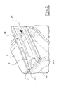
- FIG. 1 shows in the perspective view of a housing 1 in the upper region for a household appliance, such as a tumble dryer, which includes in its basic design a front wall 2, and connected by cross member 3 side walls 4 and 5 and a rear wall 6.
- a guide 7 is provided for a condensate tank, not shown.
- FIGS. 1 . 2 and 4 As from the synopsis of FIGS. 1 . 2 and 4 can be seen, is to build a frameless housing 1, the crossbar 3 on bends 8 and 9 on the side walls 4 and 5 for specifying the total width of the housing 1.
- the traverse 3 at the free ends for form-locking formation with the Abkantungs Siemensen 8 and 9 of the side walls 4 and 5 comprises a profiling 10, which comprises screw 11 and a bead connection 12.
- a profiling 10 which comprises screw 11 and a bead connection 12.
- the bead assembly designed which comprises interlocking arc sections 14 and 15, which are provided once on the cross member 3 and the fold 8, 9.
- the arc section 14 on the traverse 3 is slightly smaller than the arc section 15 at the fold 8, 9.
- the profiles 13 at the free ends of the cross member 3 is substantially an H-shape, wherein the legs of the H extend over the entire length of the cross member 3.
- the screw 11.1 and 11.2 at least one screw 11.1 is provided, which is limited in the penetration depth in the bending region of the side wall 4, 5.
- to limit the penetration depth to the front wall 2 facing screw 11.1 has a provided on the cross member 3 collar edge 16 around the opening. It understands itself now that when the fitter inserts the screw into the opening accordingly, thereby a limited screwing is given in depth, because the collar edge 16 here holds the screw in a higher position.
- the positive connection of traverse 3 and guide 7 comprises a pin-hole connection 17 and a screw 18, as in the FIG. 5 can be seen. It penetrates in the inserted state in the pre-assembly, first the pin 19 in the hole opening 20 on the cross-member 3, in which case by screwing a screw 21, the firm connection between the guide 7 and the cross member 3 takes place.
- the pin-hole connection 17 is in this case provided on the upper side wall 22 of the guide 7, as in particular in the FIG. 6 It can be seen where in the perspective view of the guide 7 between the side wall 4, the rear wall 6 and the front wall 2 is integrated.
- the guide 7 is connected to the rear wall 6 by plugging, wherein in the front region on the guide floor, a projection 23 is provided, which rests only on the front wall 2.
Landscapes
- Engineering & Computer Science (AREA)
- Textile Engineering (AREA)
- Main Body Construction Of Washing Machines And Laundry Dryers (AREA)
- Detail Structures Of Washing Machines And Dryers (AREA)
Abstract
Description
- Gehäuse für Haushaltsgeräte, wie beispielsweise einen Wäschetrockner, eine Waschmaschine oder dergleichen.
- Die Erfindung betrifft ein Gehäuse für Haushaltsgeräte, wie beispielsweise Wäschetrockner, Waschmaschinen oder dergleichen, welches in seiner Grundbauform eine Vorderwand sowie mittels Traverse verbundene Seitenwände und eine Rückwand umfasst, wobei zum Aufbau eines rahmenlosen Gehäuses die Traverse auf Abkantungen an den Seitenwänden zur Vorgabe der Gesamtbreite des Gehäuses aufliegt, wobei die Traverse mit den Abkantungen an den Seitenwänden unter Formschluss verbunden ist zur Bildung einer Winkelstabilität zwischen den das Gehäuse umfassenden Wänden.
- Aus dem Stand der Technik sind gemäß
DE 103 03 131 , derDE 198 23 424 sowie aus derDE 38 13 462 Waschmaschinengehäuse bzw. Gehäuse für Haushaltsgeräte bekannt. Bei diesen aus dem Stand der Technik bekannten Gehäusen gibt es unterschiedliche Gehäusebauformen für die die jeweilige Oberfläche oder Montageart, was eine frühe Variantenbildung beim Gehäuseaufbau erfordert. Bei diesen aus dem Stand der Technik bekannten Gehäusebauformen besteht der Nachteil, dass die von außen auf das Gerät wirkenden Lasten nicht passend verteilt werden. Die von außen sichtbaren Spaltbilder sind nicht möglichst eng und gleichmäßig ausgebildet, wobei zudem die vorgeschlagenen Gehäusebauformen sich montageunfreundlich gestalten. - Die
EP 2 468 172 A1 und dieEP 2 594 182 A1 offenbaren Gehäuse von Waschmaschinen oder Wäschetrocknern mit den eingangs genannten Merkmalen. - Aus der
EP 2 199 453 A1 ist das Gehäuse eines Kondensationswäschetrockners bekannt, wobei im oberen Bereich der Seitenwände eine Führung für einen Kondensatsammelbehälter vorgesehen ist. - Der Erfindung stellt sich somit das Problem ein Gehäuse für Haushaltsgeräte, wie beispielsweise einen Wäschetrockner, eine Waschmaschine oder einen Geschirrspüler, derart weiter zu bilden, welches einerseits die geschilderten Nachteile überwindet, wobei andererseits das Gehäuse ohne einen eigenständigen Innenrahmen gefertigt werden soll.
- Erfindungsgemäß wird dieses Problem mit den Merkmalen des Patentanspruchs 1 gelöst. Vorteilhafte Ausgestaltungen und Weiterbildungen der Erfindung ergeben sich aus den nachfolgenden Unteransprüchen.
- Die mit der Erfindung erreichten Vorteile bestehen darin, dass das erfindungsgemäße Gehäuse ohne einen eigenständigen Innenrahmen gefertigt werden kann. Die von außen wirkenden Lasten auf das Gerät werden dabei passend verteilt, wobei die von außen sichtbaren Spaltbilder möglichst eng und gleichmäßig ausgebildet sind. Ein besonderer Vorteil ist, dass der gewählte Aufbau zudem sehr montagefreundlich ausfällt. Dabei ist von besonderer Bedeutung, dass die Montage/Demontage der Seitenwände, der Traverse und der Führung für den Behälter gewährleistet ist, wobei eine definierte Aufhängung und fixierende Ausrichtung der freitragenden Seitenwände zu der Vorderwand und der Rückwand gegeben ist. Entsprechend erfüllt auch eine definierte Lage der Führung für den Behälter in dem Gerät diese Aufgabe. Eine Verletzungsgefahr des Kunden bei evtl. Säubern der Führung durch Hineingreifen in die Führung wird dadurch verhindert, weil durch die Verbindung der beiden Seitenwände mittels der Traverse eine definierte Montage und Endlage-Position der Führung geschaffen wird. Dabei werden bei dem erfindungsgemäßen Gehäuse von außen seitlich wirkende Lasten, wie beispielsweise beim Transport, aufgenommen und in das Gerät über die Traverse weitergeleitet. Die Führung für den Kondensatbehälter wird hinten in der Rückwand fixiert, wodurch eine feste Y-Ausrichtung und Z-Ausrichtung hinten erfolgt. Vorne wird die Führung auf der Vorderwand aufgelegt, so dass vorne eine feste Z-Ausrichtung gegeben ist. Die Traverse wird von oben über die Seitenwände aufgelegt. Eine grobe Y-Ausrichtung ist dabei über die an den Seitewänden vorgesehenen Abkantungen rechts und links gegeben. Für die grobe X-Ausrichtung der Traverse zu den Seitenwänden greift jeweils links und rechts eine Sicke der Traverse in eine entsprechend große Sicke der Seitenwand. Dann wird die Traverse in Y-Richtung genau ausgerichtet und mit den beiden Seitenwänden verschraubt. Dadurch erhält das erstellte erfindungsgemäße Gehäuse, bestehend aus Vorderwand, Seitenwand, Rückwand und Traverse insbesondere im Traversenbereich eine deutliche Winkelstabilität bzw. Gehäusesteifigkeit. Damit der Wasserbehälter nicht beschädigt wird und der Kunde beim evtl. Säubern der Führung unter anderem bei herausgezogenem Wasserbehälter durch Schraubenspitzen gefährdet ist, ist an der Traverse ein Kragenrand vorgesehen, der dafür sorgt, dass die Schraube bzw. Schrauben nicht zu tief in den Bereich der Führung eintauchen. Bei Auflegen der Traverse greift ein Zapfen der Führung in ein Lochbild der Traverse. Dadurch wird die X-Ausrichtung und die Y-Ausrichtung der Führung vorne definiert. Hierbei sichert insbesondere eine Schraube diese Position.
- Erfindungsgemäß wird vorgeschlagen, dass die Traverse an den freien Enden zur Formschlussbildung mit den Abkantungsbereichen der Seitenwände eine Profilierung umfasst, welche Schraubverbindungen und eine Sickenverbindung aufweisen. Dabei sind an den freien Enden jeweils wenigstens zwei Schraubverbindungen vorgesehen, wobei zwischen den Schraubverbindungen die Sickenverbindung und Profilierungen an der Traverse angeordnet sind. Die Sickenverbindung, die die Schraubverbindungen im Formschluss hierbei unterstützt, erhält insbesondere durch die Profilierung an der Traverse ihre Steifigkeit, die sich über die Erstreckung der Traverse ausrichtet.
- Nach einer vorteilhaften Ausgestaltung der Erfindung umfasst der Sickenverbund ineinander greifende Bogenabschnitte an der Traverse und der Abkantung, wobei der Bogenabschnitt an der Traverse etwas kleiner als der Bogenabschnitt an der Abkantung ausgebildet ist. Dadurch ergibt sich ein Passsitz im Formschluss der Sickenverbindung. In Weiterbildung der Profilierung an der Traverse ist diese an den freien Enden der Traverse im Wesentlichen H-förmig ausgebildet.
- In zweckmäßiger Weise umfassen die Schraubverbindungen wenigstens eine Schraubverbindung, die die Eindringtiefe in den Abkantungsbereich der Seitenwand begrenzt. Dabei weist zur Begrenzung der Eindringtiefe die zur Vorderwand weisende Schraubverbindung einen an der Traverse vorgesehenen Kragenrand um die Öffnung auf. Aufgrund dieser Ausbildung wird erreicht, dass die Schraubenspitze im vorderen Bereich der Führung nicht so tief in den Führungsraum eindringt, so dass bei Eingriff mit der Hand in den Führungsraum Verletzungen unterbunden werden. In Weiterbildung umfasst die Formschlussverbindung von Traverse und Führung eine Zapfen-Loch-Verbindung sowie eine Schraubverbindung. Um die Formschlussverbindung zwischen der Traverse und der Führung herzustellen, erfolgt diese mittels einer Zapfen-Loch-Verbindung, wobei dies eine montagefreundliche Art zum Ansetzen der Führung an die montierte Traverse ermöglicht. Dabei wird zunächst die Führung im hinteren Bereich der Rückwand eingesteckt, wobei dann im vorderen Bereich infolge der Zapfen-Loch-Verbindung diese einfach in die vormontierte Traverse gedrückt wird, wobei dann durch eine Schraubverbindung diese dann endgültig festgelegt wird. Im vorderen Bereich liegt hierbei die Führung lediglich auf der Vorderwand auf.
- Ein Ausführungsbeispiel der Erfindung ist in den Zeichnungen rein schematisch dargestellt und wird nachfolgend näher beschrieben. Es zeigt:
- Figur 1
- eine perspektivische Darstellung auf das Gehäuse mit Führung und Traverse im Verbund;
- Figur 2
- eine Detailansicht der Traverse im Einbindungsbereich von Seitenwand und Führung;
- Figur 3
- eine Einzeldarstellung in explosionsartiger Darstellung von Traverse und Seitenwand;
- Figur 4
- eine Seitenansicht der Traverse unter Einbindung an der Abkantung der Seitenwand;
- Figur 5
- eine geschnittene Seitenansicht von Traverse und Führung;
- Figur 6
- eine perspektivische Darstellung der Führung in Einbindung im Gehäuse von Seitenwand und Rückwand.
- Die
Figur 1 zeigt in der perspektivischen Darstellung ein Gehäuse 1 im oberen Bereich für ein Haushaltsgerät, wie beispielsweise einen Wäschetrockner, welches in seiner Grundbauform eine Vorderwand 2, sowie mittels Traverse 3 verbundene Seitenwände 4 und 5 und eine Rückwand 6 umfasst. Wie insbesondere in der Darstellung derFigur 1 zu erkennen ist, ist im oberen Bereich von Seitenwand 4 und 5 die Traverse 3, unter Einbindung des Rückwandbereichs, eine Führung 7 für einen nicht näher dargestellten Kondensatbehälter vorgesehen. Wie aus der Zusammenschau derFiguren 1 ,2 und4 zu erkennen ist, liegt zum Aufbau eines rahmenlosen Gehäuses 1 die Traverse 3 auf Abkantungen 8 und 9 an den Seitenwänden 4 und 5 zur Vorgabe der Gesamtbreite des Gehäuses 1. Dabei ist die Traverse 3 mit den Abkantungen 8 und 9 an den Seitenwänden 4 und 5 unter Formschluss verbunden. Mit der Traverse 3 ist ebenfalls unter Formschluss die Führung 7 verbunden, zur Bildung einer Winkelstabilität zwischen den das Gehäuse umfassenden Wänden 2, 4, 5 und 6. Durch den Verbund der Seitenwänden 4 und 5 mit der Traverse 3, wobei unterhalb der Traverse 3 die Führung 7 eingebunden ist, die wiederum zwischen Vorderwand 2 und Rückwand 6 eingebunden ist, ergibt sich eine kreuzartige, innen liegende Verbundwirkung zwischen den Wänden 2, 4, 5 und 6, wobei die versteifende Wirkung für das rahmenloses Gehäuse 1 vornehmlich durch die erfindungsgemäße Einbindung der Traverse 3 begünstig wird. - Dabei umfasst die Traverse 3 an den freien Enden zur Formschlussbildung mit den Abkantungsbereichen 8 und 9 der Seitenwände 4 und 5 eine Profilierung 10, welche Schraubverbindungen 11 und eine Sickenverbindung 12 umfasst. Dabei sind an den freien Enden jeweils wenigstens zwei Schraubverbindungen 11.1 und 11.2 zwischen denen die Sickenverbindung 12 und Profilierungen 13 an der Traverse 3 angeordnet sind. Insbesondere aus der
Figur 4 ist erkennbar, wie sich der Sickenverbund gestaltet, wobei dieser ineinandergreifende Bogenabschnitte 14 und 15 umfasst, die einmal an der Traverse 3 und an der Abkantung 8, 9 vorgesehen sind. Aus derFigur 4 ist ersichtlich, dass dabei der Bogenabschnitt 14 an der Traverse 3 etwas kleiner als der Bogenabschnitt 15 an der Abkantung 8, 9 ist. Wie noch aus denFiguren 2 und3 ersichtlich ist, umfassen die Profilierungen 13 an den freien Enden der Traverse 3 im Wesentlichen eine H-Form, wobei die Schenkel des H's sich über die gesamte Länge der Traverse 3 erstrecken. - Bei den Schraubverbindungen 11.1 und 11.2 ist wenigstens eine Schraubverbindung 11.1 vorgesehen, die in der Eindringtiefe in den Abkantungsbereich der Seitenwand 4, 5 begrenzt ist. Dabei weist die zur Begrenzung der Eindringtiefe zur Vorderwand 2 weisende Schraubverbindung 11.1 einen an der Traverse 3 vorgesehenen Kragenrand 16 um die Öffnung auf. Es versteht sich nun von selbst, dass, wenn der Monteur die Schraube entsprechend in die Öffnung einsetzt, dadurch eine begrenzte Schraubung in der Tiefe gegeben ist, weil der Kragenrand 16 hier die Schraube in einer höheren Position hält.
- In Weiterbildung der Erfindung umfasst die Formschlussverbindung von Traverse 3 und Führung 7 eine Zapfen-Loch-Verbindung 17 sowie eine Schraubverbindung 18, wie diese in der
Figur 5 zu erkennen ist. Dabei dringt im gesteckten Zustand in der Vormontage zunächst der Zapfen 19 in die Lochöffnung 20 an der Traverse 3, wobei dann unter Eindrehen einer Schraube 21 die feste Verbindung zwischen der Führung 7 und der Traverse 3 erfolgt. Die Zapfen-Loch-Verbindung 17 ist hierbei auf der oberen Seitenwand 22 der Führung 7 vorgesehen, wie dies insbesondere in derFigur 6 zu erkennen ist, wo in der perspektivischen Darstellung die Führung 7 zwischen der Seitenwand 4, der Rückwand 6 und der Vorderwand 2 eingebunden ist. Dort ist zu erkennen, dass im rückwärtigen Bereich die Führung 7 an der Rückwand 6 durch Einstecken verbunden ist, wobei im vorderen Bereich am Führungsboden ein Ansatz 23 vorgesehen ist, der lediglich auf der Vorderwand 2 aufliegt. Dadurch erhält die Führung 7 in dem Gehäuse 1 eine feste Einbindung, wobei ihre obere Abstützung durch die Traverse 3 in Form der Zapfen-Loch-Verbindung 17 erfolgt.
Claims (7)
- Gehäuse (1) für Haushaltsgeräte, wie beispielsweise einen Wäschetrockner, eine Waschmaschine oder dergleichen, welches in seiner Grundbauform eine Vorderwand (2) sowie mittels Traverse (3) verbundene Seitenwände (4) und (5) und eine Rückwand (6) umfasst, wobei zum Aufbau eines rahmenlosen Gehäuses (1) die Traverse (3) auf Abkantungen (8) und (9) an den Seitenwänden (4) und (5) zur Vorgabe der Gesamtbreite des Gehäuses (1) aufliegt, wobei die Traverse (3) mit den Abkantungen (8) und (9) an den Seitenwänden (4) und (5) unter Formschluss verbunden ist zur Bildung einer Winkelstabilität zwischen den das Gehäuse umfassenden Wänden (2, 4, 5 und 6),
dadurch gekennzeichnet,
dass im oberen Bereich von Seitenwand (4) und (5) und Traverse (3) mit Einbindung des Rückwandbereichs eine Führung (7) für einen Kondensatbehälter vorgesehen ist, und dass die Traverse (3) an den freien Enden zur Formschlussbildung mit den Abkantungsbereichen der Seitenwände (4) und (5) eine Profilierung (10) umfasst, welche Schraubverbindungen (11) und eine Sickenverbindung (12) aufweisen. - Gehäuse nach Anspruch 1,
dadurch gekennzeichnet,
dass an den freien Enden jeweils wenigstens zwei Schraubverbindungen (11.1) und (11.2) vorgesehen sind, wobei zwischen den Schraubverbindungen (11.1) und (11.2) die Sickenverbindung (12) und Profilierungen (13) an der Traverse (3) angeordnet sind. - Gehäuse nach Anspruch 2,
dadurch gekennzeichnet,
dass der Sickenverbund ineinandergreifende Bogenabschnitte (14) und (15) an der Traverse (3) und der Abkantung (8, 9) umfasst, wobei der Bogenabschnitt (14) an der Traverse (3) etwas kleiner als der Bogenabschnitt (15) an der Abkantung (8, 9) ausgebildet ist. - Gehäuse nach Anspruch 2 oder 3,
dadurch gekennzeichnet,
dass die Profilierungen (13) an den freien Enden der Traverse (3) im Wesentlichen eine H-Form umfassen. - Gehäuse nach Anspruch 2 bis 4,
dadurch gekennzeichnet,
dass die Schraubverbindungen (11.1 und 11.2) wenigstens eine Schraubverbindung (11.1) umfasst, die die Eindringtiefe in den Abkantungsbereich der Seitenwand (8, 9) begrenzt. - Gehäuse nach Anspruch 5,
dadurch gekennzeichnet,
dass zur Begrenzung der Eindringtiefe die zur Vorderwand (2) weisende Schraubverbindung (11.1) einen an der Traverse (3) vorgesehenen Kragenrand (16) um die Öffnung aufweist. - Gehäuse nach einem der Ansprüche 1 bis 6,
dadurch gekennzeichnet,
dass die Formschlussverbindung von Traverse (3) und Führung (7) eine Zapfen-Loch-Verbindung (17) sowie eine Schraubverbindung (18) umfasst.
Applications Claiming Priority (1)
| Application Number | Priority Date | Filing Date | Title |
|---|---|---|---|
| DE201310102510 DE102013102510A1 (de) | 2013-03-13 | 2013-03-13 | Gehäuse für Haushaltsgeräte, wie beispielsweise einen Wäschetrockner, eine Waschmaschine oder dergleichen |
Publications (3)
| Publication Number | Publication Date |
|---|---|
| EP2778277A2 true EP2778277A2 (de) | 2014-09-17 |
| EP2778277A3 EP2778277A3 (de) | 2014-11-05 |
| EP2778277B1 EP2778277B1 (de) | 2016-03-09 |
Family
ID=50238272
Family Applications (1)
| Application Number | Title | Priority Date | Filing Date |
|---|---|---|---|
| EP14158765.9A Not-in-force EP2778277B1 (de) | 2013-03-13 | 2014-03-11 | Gehäuse für Haushaltsgeräte, wie beispielsweise einen Wäschetrockner, eine Waschmaschine oder dergleichen |
Country Status (2)
| Country | Link |
|---|---|
| EP (1) | EP2778277B1 (de) |
| DE (1) | DE102013102510A1 (de) |
Families Citing this family (2)
| Publication number | Priority date | Publication date | Assignee | Title |
|---|---|---|---|---|
| CN115110270B (zh) * | 2021-03-19 | 2025-11-28 | 上海海尔洗涤电器有限公司 | 一种台面结构及洗烘一体设备 |
| LU103281B1 (de) * | 2024-04-23 | 2025-10-23 | Miele & Cie | Wäschebehandlungsgerät mit einem Gehäuse |
Citations (6)
| Publication number | Priority date | Publication date | Assignee | Title |
|---|---|---|---|---|
| DE3813462A1 (de) | 1987-04-21 | 1988-11-10 | Candy Ind Spa | Waschmaschinengehaeuse |
| DE19823424A1 (de) | 1998-05-26 | 1999-12-02 | Aeg Hausgeraete Gmbh | Gerätegehäuse, insbesondere für Haushaltsgroßgeräte |
| DE10303131A1 (de) | 2003-01-28 | 2004-07-29 | Electrolux Home Products Corporation N.V. | Haushaltgerät und Gehäuse für das Haushaltgerät |
| EP2199453A1 (de) | 2008-12-17 | 2010-06-23 | Electrolux Home Products Corporation N.V. | Haushaltsgerät |
| EP2468172A1 (de) | 2010-12-24 | 2012-06-27 | BSH Bosch und Siemens Hausgeräte GmbH | Haushaltsgerät-Gehäusekörper |
| EP2594182A1 (de) | 2011-11-18 | 2013-05-22 | Miele & Cie. KG | Gehäuse für Haushaltsgeräte wie Waschmaschinen, Wäschetrockner oder Geschirrspülmaschinen |
Family Cites Families (8)
| Publication number | Priority date | Publication date | Assignee | Title |
|---|---|---|---|---|
| DE4139588A1 (de) * | 1990-12-15 | 1992-06-17 | Miele & Cie | Haushaltgeraet |
| US7251905B2 (en) * | 2003-12-22 | 2007-08-07 | Lg Electronics Inc. | Condensed water storing apparatus of a dryer |
| GB2428287A (en) * | 2005-07-13 | 2007-01-24 | Indesit Company Uk Ltd | Pumping system for a condenser tumble dryer |
| EP1887127B1 (de) * | 2006-08-08 | 2016-10-26 | Electrolux Home Products Corporation N.V. | Wäschebehandlungsmaschine |
| EP3109358B1 (de) * | 2009-06-29 | 2018-08-22 | Electrolux Home Products Corporation N.V. | Vorrichtung zum wäschetrocknen |
| EP2287389A1 (de) * | 2009-08-18 | 2011-02-23 | BSH Bosch und Siemens Hausgeräte GmbH | Dampfeinspritzvorrichtung für ein Wäschebehandlungsgerät und Wäschebehandlungsgerät |
| EP2458067B1 (de) * | 2010-11-29 | 2013-07-03 | Electrolux Home Products Corporation N.V. | Wäschetrockner |
| SE537671C2 (sv) * | 2011-08-15 | 2015-09-29 | Asko Cylinda Ab | Klädestorktumlare med mekanism för luddfilterrengöring |
-
2013
- 2013-03-13 DE DE201310102510 patent/DE102013102510A1/de not_active Withdrawn
-
2014
- 2014-03-11 EP EP14158765.9A patent/EP2778277B1/de not_active Not-in-force
Patent Citations (6)
| Publication number | Priority date | Publication date | Assignee | Title |
|---|---|---|---|---|
| DE3813462A1 (de) | 1987-04-21 | 1988-11-10 | Candy Ind Spa | Waschmaschinengehaeuse |
| DE19823424A1 (de) | 1998-05-26 | 1999-12-02 | Aeg Hausgeraete Gmbh | Gerätegehäuse, insbesondere für Haushaltsgroßgeräte |
| DE10303131A1 (de) | 2003-01-28 | 2004-07-29 | Electrolux Home Products Corporation N.V. | Haushaltgerät und Gehäuse für das Haushaltgerät |
| EP2199453A1 (de) | 2008-12-17 | 2010-06-23 | Electrolux Home Products Corporation N.V. | Haushaltsgerät |
| EP2468172A1 (de) | 2010-12-24 | 2012-06-27 | BSH Bosch und Siemens Hausgeräte GmbH | Haushaltsgerät-Gehäusekörper |
| EP2594182A1 (de) | 2011-11-18 | 2013-05-22 | Miele & Cie. KG | Gehäuse für Haushaltsgeräte wie Waschmaschinen, Wäschetrockner oder Geschirrspülmaschinen |
Also Published As
| Publication number | Publication date |
|---|---|
| EP2778277A3 (de) | 2014-11-05 |
| DE102013102510A1 (de) | 2014-09-18 |
| EP2778277B1 (de) | 2016-03-09 |
Similar Documents
| Publication | Publication Date | Title |
|---|---|---|
| DE112013007225B4 (de) | Doppeltrommelwaschmaschine | |
| EP3535822B1 (de) | Schaltschrank mit einer montageplattenanordnung | |
| DE202008004100U1 (de) | Teleskopierbare Auszugsführung | |
| DE102008029606A1 (de) | Gelenkstruktur zum Zusammenfalten eines Baby-Netzbetts | |
| EP2778276B1 (de) | Gehäuse für Haushaltsgeräte sowie Verfahren zur Herrichtung eines Gehäuses für Haushaltsgeräte | |
| EP2778277B1 (de) | Gehäuse für Haushaltsgeräte, wie beispielsweise einen Wäschetrockner, eine Waschmaschine oder dergleichen | |
| EP2062502A1 (de) | Lagerregal | |
| EP3000957B1 (de) | Steckrahmensystem | |
| EP3519737A1 (de) | Traggestell für einen gargutträger, baugruppe mit einem traggestell, sowie haushaltsgerät | |
| EP3183386B1 (de) | Bodenmodul für ein haushaltsgerät | |
| EP2801652A1 (de) | Gehäuse für ein Haushaltsgerät wie beispielsweise einen Wäschetrockner sowie ein Verfahren zur Herstellung eines Gehäuses | |
| EP2718058B1 (de) | Faltenbalg | |
| DE10116471B4 (de) | Aufhängungseinheit für Einschübe für einen Backofen | |
| EP2134891B1 (de) | Breithalterzylinder, insbesondere für eine webmaschine | |
| EP2778278B1 (de) | Gehäuse für haushaltsgeräte wie beispielsweise einen wäschetrockner, eine waschmaschine, oder dergleichen | |
| EP1876924B1 (de) | Regal zur aufnahme von gegenständen | |
| DE102008054463A1 (de) | Hausgerät zur Pflege von Wäschestücken, mit einer Trommel und einer Manschette | |
| DE102025113296B3 (de) | Kleinteilehalter und Wäschetrocknungsgestell | |
| EP2151513B1 (de) | Oberwalzen-Trag- und Belastungsarm | |
| DE102013102509A1 (de) | Gehäuse für Haushaltsgeräte wie beispielsweise Wäschetrockner, Waschmaschine, Geschirrspülmaschine oder dergleichen | |
| DE102008039198B4 (de) | Verbindungseinrichtung zur schwenkbaren Verbindung zweier Bauteile, insbesondere eines Zeltes | |
| EP2672000B1 (de) | Wäschetrockner | |
| EP2881015B1 (de) | Türgarderobe | |
| DE102005037508A1 (de) | Kassettenmarkise | |
| DE102014115060B4 (de) | Verbindungseinrichtung |
Legal Events
| Date | Code | Title | Description |
|---|---|---|---|
| 17P | Request for examination filed |
Effective date: 20140311 |
|
| AK | Designated contracting states |
Kind code of ref document: A2 Designated state(s): AL AT BE BG CH CY CZ DE DK EE ES FI FR GB GR HR HU IE IS IT LI LT LU LV MC MK MT NL NO PL PT RO RS SE SI SK SM TR |
|
| AX | Request for extension of the european patent |
Extension state: BA ME |
|
| PUAI | Public reference made under article 153(3) epc to a published international application that has entered the european phase |
Free format text: ORIGINAL CODE: 0009012 |
|
| PUAL | Search report despatched |
Free format text: ORIGINAL CODE: 0009013 |
|
| AK | Designated contracting states |
Kind code of ref document: A3 Designated state(s): AL AT BE BG CH CY CZ DE DK EE ES FI FR GB GR HR HU IE IS IT LI LT LU LV MC MK MT NL NO PL PT RO RS SE SI SK SM TR |
|
| AX | Request for extension of the european patent |
Extension state: BA ME |
|
| RIC1 | Information provided on ipc code assigned before grant |
Ipc: D06F 58/20 20060101ALI20141002BHEP Ipc: D06F 39/12 20060101AFI20141002BHEP Ipc: D06F 58/24 20060101ALI20141002BHEP |
|
| R17P | Request for examination filed (corrected) |
Effective date: 20150506 |
|
| RBV | Designated contracting states (corrected) |
Designated state(s): AL AT BE BG CH CY CZ DE DK EE ES FI FR GB GR HR HU IE IS IT LI LT LU LV MC MK MT NL NO PL PT RO RS SE SI SK SM TR |
|
| GRAP | Despatch of communication of intention to grant a patent |
Free format text: ORIGINAL CODE: EPIDOSNIGR1 |
|
| INTG | Intention to grant announced |
Effective date: 20151012 |
|
| GRAS | Grant fee paid |
Free format text: ORIGINAL CODE: EPIDOSNIGR3 |
|
| GRAA | (expected) grant |
Free format text: ORIGINAL CODE: 0009210 |
|
| AK | Designated contracting states |
Kind code of ref document: B1 Designated state(s): AL AT BE BG CH CY CZ DE DK EE ES FI FR GB GR HR HU IE IS IT LI LT LU LV MC MK MT NL NO PL PT RO RS SE SI SK SM TR |
|
| REG | Reference to a national code |
Ref country code: GB Ref legal event code: FG4D Free format text: NOT ENGLISH |
|
| REG | Reference to a national code |
Ref country code: AT Ref legal event code: REF Ref document number: 779627 Country of ref document: AT Kind code of ref document: T Effective date: 20160315 Ref country code: CH Ref legal event code: EP |
|
| REG | Reference to a national code |
Ref country code: DE Ref legal event code: R084 Ref document number: 502014000426 Country of ref document: DE |
|
| REG | Reference to a national code |
Ref country code: GB Ref legal event code: 746 Effective date: 20160302 |
|
| REG | Reference to a national code |
Ref country code: IE Ref legal event code: FG4D Free format text: LANGUAGE OF EP DOCUMENT: GERMAN |
|
| REG | Reference to a national code |
Ref country code: DE Ref legal event code: R096 Ref document number: 502014000426 Country of ref document: DE |
|
| REG | Reference to a national code |
Ref country code: FR Ref legal event code: PLFP Year of fee payment: 3 |
|
| REG | Reference to a national code |
Ref country code: LT Ref legal event code: MG4D |
|
| REG | Reference to a national code |
Ref country code: NL Ref legal event code: MP Effective date: 20160309 |
|
| PG25 | Lapsed in a contracting state [announced via postgrant information from national office to epo] |
Ref country code: ES Free format text: LAPSE BECAUSE OF FAILURE TO SUBMIT A TRANSLATION OF THE DESCRIPTION OR TO PAY THE FEE WITHIN THE PRESCRIBED TIME-LIMIT Effective date: 20160309 Ref country code: NO Free format text: LAPSE BECAUSE OF FAILURE TO SUBMIT A TRANSLATION OF THE DESCRIPTION OR TO PAY THE FEE WITHIN THE PRESCRIBED TIME-LIMIT Effective date: 20160609 Ref country code: HR Free format text: LAPSE BECAUSE OF FAILURE TO SUBMIT A TRANSLATION OF THE DESCRIPTION OR TO PAY THE FEE WITHIN THE PRESCRIBED TIME-LIMIT Effective date: 20160309 Ref country code: FI Free format text: LAPSE BECAUSE OF FAILURE TO SUBMIT A TRANSLATION OF THE DESCRIPTION OR TO PAY THE FEE WITHIN THE PRESCRIBED TIME-LIMIT Effective date: 20160309 Ref country code: GR Free format text: LAPSE BECAUSE OF FAILURE TO SUBMIT A TRANSLATION OF THE DESCRIPTION OR TO PAY THE FEE WITHIN THE PRESCRIBED TIME-LIMIT Effective date: 20160610 |
|
| PG25 | Lapsed in a contracting state [announced via postgrant information from national office to epo] |
Ref country code: BE Free format text: LAPSE BECAUSE OF NON-PAYMENT OF DUE FEES Effective date: 20160331 Ref country code: NL Free format text: LAPSE BECAUSE OF FAILURE TO SUBMIT A TRANSLATION OF THE DESCRIPTION OR TO PAY THE FEE WITHIN THE PRESCRIBED TIME-LIMIT Effective date: 20160309 Ref country code: LT Free format text: LAPSE BECAUSE OF FAILURE TO SUBMIT A TRANSLATION OF THE DESCRIPTION OR TO PAY THE FEE WITHIN THE PRESCRIBED TIME-LIMIT Effective date: 20160309 Ref country code: RS Free format text: LAPSE BECAUSE OF FAILURE TO SUBMIT A TRANSLATION OF THE DESCRIPTION OR TO PAY THE FEE WITHIN THE PRESCRIBED TIME-LIMIT Effective date: 20160309 Ref country code: LV Free format text: LAPSE BECAUSE OF FAILURE TO SUBMIT A TRANSLATION OF THE DESCRIPTION OR TO PAY THE FEE WITHIN THE PRESCRIBED TIME-LIMIT Effective date: 20160309 Ref country code: PL Free format text: LAPSE BECAUSE OF FAILURE TO SUBMIT A TRANSLATION OF THE DESCRIPTION OR TO PAY THE FEE WITHIN THE PRESCRIBED TIME-LIMIT Effective date: 20160309 Ref country code: SE Free format text: LAPSE BECAUSE OF FAILURE TO SUBMIT A TRANSLATION OF THE DESCRIPTION OR TO PAY THE FEE WITHIN THE PRESCRIBED TIME-LIMIT Effective date: 20160309 |
|
| PG25 | Lapsed in a contracting state [announced via postgrant information from national office to epo] |
Ref country code: EE Free format text: LAPSE BECAUSE OF FAILURE TO SUBMIT A TRANSLATION OF THE DESCRIPTION OR TO PAY THE FEE WITHIN THE PRESCRIBED TIME-LIMIT Effective date: 20160309 Ref country code: IS Free format text: LAPSE BECAUSE OF FAILURE TO SUBMIT A TRANSLATION OF THE DESCRIPTION OR TO PAY THE FEE WITHIN THE PRESCRIBED TIME-LIMIT Effective date: 20160709 |
|
| PG25 | Lapsed in a contracting state [announced via postgrant information from national office to epo] |
Ref country code: RO Free format text: LAPSE BECAUSE OF FAILURE TO SUBMIT A TRANSLATION OF THE DESCRIPTION OR TO PAY THE FEE WITHIN THE PRESCRIBED TIME-LIMIT Effective date: 20160309 Ref country code: SK Free format text: LAPSE BECAUSE OF FAILURE TO SUBMIT A TRANSLATION OF THE DESCRIPTION OR TO PAY THE FEE WITHIN THE PRESCRIBED TIME-LIMIT Effective date: 20160309 Ref country code: SM Free format text: LAPSE BECAUSE OF FAILURE TO SUBMIT A TRANSLATION OF THE DESCRIPTION OR TO PAY THE FEE WITHIN THE PRESCRIBED TIME-LIMIT Effective date: 20160309 Ref country code: PT Free format text: LAPSE BECAUSE OF FAILURE TO SUBMIT A TRANSLATION OF THE DESCRIPTION OR TO PAY THE FEE WITHIN THE PRESCRIBED TIME-LIMIT Effective date: 20160711 Ref country code: CZ Free format text: LAPSE BECAUSE OF FAILURE TO SUBMIT A TRANSLATION OF THE DESCRIPTION OR TO PAY THE FEE WITHIN THE PRESCRIBED TIME-LIMIT Effective date: 20160309 |
|
| REG | Reference to a national code |
Ref country code: DE Ref legal event code: R097 Ref document number: 502014000426 Country of ref document: DE |
|
| REG | Reference to a national code |
Ref country code: IE Ref legal event code: MM4A |
|
| PG25 | Lapsed in a contracting state [announced via postgrant information from national office to epo] |
Ref country code: IT Free format text: LAPSE BECAUSE OF FAILURE TO SUBMIT A TRANSLATION OF THE DESCRIPTION OR TO PAY THE FEE WITHIN THE PRESCRIBED TIME-LIMIT Effective date: 20160309 |
|
| PLBE | No opposition filed within time limit |
Free format text: ORIGINAL CODE: 0009261 |
|
| STAA | Information on the status of an ep patent application or granted ep patent |
Free format text: STATUS: NO OPPOSITION FILED WITHIN TIME LIMIT |
|
| PG25 | Lapsed in a contracting state [announced via postgrant information from national office to epo] |
Ref country code: DK Free format text: LAPSE BECAUSE OF FAILURE TO SUBMIT A TRANSLATION OF THE DESCRIPTION OR TO PAY THE FEE WITHIN THE PRESCRIBED TIME-LIMIT Effective date: 20160309 Ref country code: IE Free format text: LAPSE BECAUSE OF NON-PAYMENT OF DUE FEES Effective date: 20160311 |
|
| 26N | No opposition filed |
Effective date: 20161212 |
|
| PG25 | Lapsed in a contracting state [announced via postgrant information from national office to epo] |
Ref country code: BG Free format text: LAPSE BECAUSE OF FAILURE TO SUBMIT A TRANSLATION OF THE DESCRIPTION OR TO PAY THE FEE WITHIN THE PRESCRIBED TIME-LIMIT Effective date: 20160609 |
|
| REG | Reference to a national code |
Ref country code: FR Ref legal event code: PLFP Year of fee payment: 4 |
|
| PG25 | Lapsed in a contracting state [announced via postgrant information from national office to epo] |
Ref country code: SI Free format text: LAPSE BECAUSE OF FAILURE TO SUBMIT A TRANSLATION OF THE DESCRIPTION OR TO PAY THE FEE WITHIN THE PRESCRIBED TIME-LIMIT Effective date: 20160309 |
|
| PG25 | Lapsed in a contracting state [announced via postgrant information from national office to epo] |
Ref country code: MT Free format text: LAPSE BECAUSE OF FAILURE TO SUBMIT A TRANSLATION OF THE DESCRIPTION OR TO PAY THE FEE WITHIN THE PRESCRIBED TIME-LIMIT Effective date: 20160309 |
|
| REG | Reference to a national code |
Ref country code: CH Ref legal event code: PL |
|
| PG25 | Lapsed in a contracting state [announced via postgrant information from national office to epo] |
Ref country code: LI Free format text: LAPSE BECAUSE OF NON-PAYMENT OF DUE FEES Effective date: 20170331 Ref country code: CH Free format text: LAPSE BECAUSE OF NON-PAYMENT OF DUE FEES Effective date: 20170331 |
|
| REG | Reference to a national code |
Ref country code: FR Ref legal event code: PLFP Year of fee payment: 5 |
|
| PG25 | Lapsed in a contracting state [announced via postgrant information from national office to epo] |
Ref country code: HU Free format text: LAPSE BECAUSE OF FAILURE TO SUBMIT A TRANSLATION OF THE DESCRIPTION OR TO PAY THE FEE WITHIN THE PRESCRIBED TIME-LIMIT; INVALID AB INITIO Effective date: 20140311 |
|
| PG25 | Lapsed in a contracting state [announced via postgrant information from national office to epo] |
Ref country code: LU Free format text: LAPSE BECAUSE OF NON-PAYMENT OF DUE FEES Effective date: 20160311 Ref country code: MC Free format text: LAPSE BECAUSE OF FAILURE TO SUBMIT A TRANSLATION OF THE DESCRIPTION OR TO PAY THE FEE WITHIN THE PRESCRIBED TIME-LIMIT Effective date: 20160309 Ref country code: MK Free format text: LAPSE BECAUSE OF FAILURE TO SUBMIT A TRANSLATION OF THE DESCRIPTION OR TO PAY THE FEE WITHIN THE PRESCRIBED TIME-LIMIT Effective date: 20160309 Ref country code: TR Free format text: LAPSE BECAUSE OF FAILURE TO SUBMIT A TRANSLATION OF THE DESCRIPTION OR TO PAY THE FEE WITHIN THE PRESCRIBED TIME-LIMIT Effective date: 20160309 Ref country code: CY Free format text: LAPSE BECAUSE OF FAILURE TO SUBMIT A TRANSLATION OF THE DESCRIPTION OR TO PAY THE FEE WITHIN THE PRESCRIBED TIME-LIMIT Effective date: 20160309 |
|
| PG25 | Lapsed in a contracting state [announced via postgrant information from national office to epo] |
Ref country code: AL Free format text: LAPSE BECAUSE OF FAILURE TO SUBMIT A TRANSLATION OF THE DESCRIPTION OR TO PAY THE FEE WITHIN THE PRESCRIBED TIME-LIMIT Effective date: 20160309 |
|
| REG | Reference to a national code |
Ref country code: AT Ref legal event code: MM01 Ref document number: 779627 Country of ref document: AT Kind code of ref document: T Effective date: 20190311 |
|
| PG25 | Lapsed in a contracting state [announced via postgrant information from national office to epo] |
Ref country code: AT Free format text: LAPSE BECAUSE OF NON-PAYMENT OF DUE FEES Effective date: 20190311 |
|
| P01 | Opt-out of the competence of the unified patent court (upc) registered |
Effective date: 20230529 |
|
| PGFP | Annual fee paid to national office [announced via postgrant information from national office to epo] |
Ref country code: DE Payment date: 20240331 Year of fee payment: 11 Ref country code: GB Payment date: 20240319 Year of fee payment: 11 |
|
| PGFP | Annual fee paid to national office [announced via postgrant information from national office to epo] |
Ref country code: FR Payment date: 20240326 Year of fee payment: 11 |
|
| REG | Reference to a national code |
Ref country code: DE Ref legal event code: R119 Ref document number: 502014000426 Country of ref document: DE |
|
| GBPC | Gb: european patent ceased through non-payment of renewal fee |
Effective date: 20250311 |
|
| PG25 | Lapsed in a contracting state [announced via postgrant information from national office to epo] |
Ref country code: DE Free format text: LAPSE BECAUSE OF NON-PAYMENT OF DUE FEES Effective date: 20251001 |
|
| PG25 | Lapsed in a contracting state [announced via postgrant information from national office to epo] |
Ref country code: GB Free format text: LAPSE BECAUSE OF NON-PAYMENT OF DUE FEES Effective date: 20250311 |
|
| PG25 | Lapsed in a contracting state [announced via postgrant information from national office to epo] |
Ref country code: FR Free format text: LAPSE BECAUSE OF NON-PAYMENT OF DUE FEES Effective date: 20250331 |