EP2777949A2 - Pneumatic tire - Google Patents
Pneumatic tire Download PDFInfo
- Publication number
- EP2777949A2 EP2777949A2 EP14155889.0A EP14155889A EP2777949A2 EP 2777949 A2 EP2777949 A2 EP 2777949A2 EP 14155889 A EP14155889 A EP 14155889A EP 2777949 A2 EP2777949 A2 EP 2777949A2
- Authority
- EP
- European Patent Office
- Prior art keywords
- band
- modulus
- inboard
- outboard
- cord
- Prior art date
- Legal status (The legal status is an assumption and is not a legal conclusion. Google has not performed a legal analysis and makes no representation as to the accuracy of the status listed.)
- Granted
Links
- 229920001778 nylon Polymers 0.000 claims description 28
- 239000011324 bead Substances 0.000 claims description 9
- 229920006231 aramid fiber Polymers 0.000 claims description 2
- 239000004677 Nylon Substances 0.000 description 26
- 239000004760 aramid Substances 0.000 description 5
- 229920003235 aromatic polyamide Polymers 0.000 description 5
- 230000000694 effects Effects 0.000 description 4
- 239000000835 fiber Substances 0.000 description 4
- 230000003014 reinforcing effect Effects 0.000 description 4
- 230000003247 decreasing effect Effects 0.000 description 3
- 229920000297 Rayon Polymers 0.000 description 2
- 239000000463 material Substances 0.000 description 2
- 239000002964 rayon Substances 0.000 description 2
- 229910000831 Steel Inorganic materials 0.000 description 1
- 230000008520 organization Effects 0.000 description 1
- 229920003207 poly(ethylene-2,6-naphthalate) Polymers 0.000 description 1
- 229920000728 polyester Polymers 0.000 description 1
- 239000011112 polyethylene naphthalate Substances 0.000 description 1
- 239000010959 steel Substances 0.000 description 1
- 238000004804 winding Methods 0.000 description 1
Images


Classifications
-
- B—PERFORMING OPERATIONS; TRANSPORTING
- B60—VEHICLES IN GENERAL
- B60C—VEHICLE TYRES; TYRE INFLATION; TYRE CHANGING; CONNECTING VALVES TO INFLATABLE ELASTIC BODIES IN GENERAL; DEVICES OR ARRANGEMENTS RELATED TO TYRES
- B60C9/00—Reinforcements or ply arrangement of pneumatic tyres
- B60C9/18—Structure or arrangement of belts or breakers, crown-reinforcing or cushioning layers
-
- B—PERFORMING OPERATIONS; TRANSPORTING
- B60—VEHICLES IN GENERAL
- B60C—VEHICLE TYRES; TYRE INFLATION; TYRE CHANGING; CONNECTING VALVES TO INFLATABLE ELASTIC BODIES IN GENERAL; DEVICES OR ARRANGEMENTS RELATED TO TYRES
- B60C11/00—Tyre tread bands; Tread patterns; Anti-skid inserts
- B60C11/03—Tread patterns
- B60C11/0304—Asymmetric patterns
-
- B—PERFORMING OPERATIONS; TRANSPORTING
- B60—VEHICLES IN GENERAL
- B60C—VEHICLE TYRES; TYRE INFLATION; TYRE CHANGING; CONNECTING VALVES TO INFLATABLE ELASTIC BODIES IN GENERAL; DEVICES OR ARRANGEMENTS RELATED TO TYRES
- B60C11/00—Tyre tread bands; Tread patterns; Anti-skid inserts
- B60C11/03—Tread patterns
- B60C11/0327—Tread patterns characterised by special properties of the tread pattern
- B60C11/033—Tread patterns characterised by special properties of the tread pattern by the void or net-to-gross ratios of the patterns
-
- B—PERFORMING OPERATIONS; TRANSPORTING
- B60—VEHICLES IN GENERAL
- B60C—VEHICLE TYRES; TYRE INFLATION; TYRE CHANGING; CONNECTING VALVES TO INFLATABLE ELASTIC BODIES IN GENERAL; DEVICES OR ARRANGEMENTS RELATED TO TYRES
- B60C9/00—Reinforcements or ply arrangement of pneumatic tyres
- B60C9/18—Structure or arrangement of belts or breakers, crown-reinforcing or cushioning layers
- B60C9/20—Structure or arrangement of belts or breakers, crown-reinforcing or cushioning layers built-up from rubberised plies each having all cords arranged substantially parallel
- B60C9/2003—Structure or arrangement of belts or breakers, crown-reinforcing or cushioning layers built-up from rubberised plies each having all cords arranged substantially parallel characterised by the materials of the belt cords
- B60C9/2009—Structure or arrangement of belts or breakers, crown-reinforcing or cushioning layers built-up from rubberised plies each having all cords arranged substantially parallel characterised by the materials of the belt cords comprising plies of different materials
-
- B—PERFORMING OPERATIONS; TRANSPORTING
- B60—VEHICLES IN GENERAL
- B60C—VEHICLE TYRES; TYRE INFLATION; TYRE CHANGING; CONNECTING VALVES TO INFLATABLE ELASTIC BODIES IN GENERAL; DEVICES OR ARRANGEMENTS RELATED TO TYRES
- B60C9/00—Reinforcements or ply arrangement of pneumatic tyres
- B60C9/18—Structure or arrangement of belts or breakers, crown-reinforcing or cushioning layers
- B60C9/30—Structure or arrangement of belts or breakers, crown-reinforcing or cushioning layers asymmetric to the midcircumferential plane of the tyre
-
- B—PERFORMING OPERATIONS; TRANSPORTING
- B60—VEHICLES IN GENERAL
- B60C—VEHICLE TYRES; TYRE INFLATION; TYRE CHANGING; CONNECTING VALVES TO INFLATABLE ELASTIC BODIES IN GENERAL; DEVICES OR ARRANGEMENTS RELATED TO TYRES
- B60C9/00—Reinforcements or ply arrangement of pneumatic tyres
- B60C9/18—Structure or arrangement of belts or breakers, crown-reinforcing or cushioning layers
- B60C9/20—Structure or arrangement of belts or breakers, crown-reinforcing or cushioning layers built-up from rubberised plies each having all cords arranged substantially parallel
- B60C9/22—Structure or arrangement of belts or breakers, crown-reinforcing or cushioning layers built-up from rubberised plies each having all cords arranged substantially parallel the plies being arranged with all cords disposed along the circumference of the tyre
- B60C2009/2223—Structure or arrangement of belts or breakers, crown-reinforcing or cushioning layers built-up from rubberised plies each having all cords arranged substantially parallel the plies being arranged with all cords disposed along the circumference of the tyre with an interrupted zero degree ply, e.g. using two or more portions for the same ply
-
- B—PERFORMING OPERATIONS; TRANSPORTING
- B60—VEHICLES IN GENERAL
- B60C—VEHICLE TYRES; TYRE INFLATION; TYRE CHANGING; CONNECTING VALVES TO INFLATABLE ELASTIC BODIES IN GENERAL; DEVICES OR ARRANGEMENTS RELATED TO TYRES
- B60C9/00—Reinforcements or ply arrangement of pneumatic tyres
- B60C9/18—Structure or arrangement of belts or breakers, crown-reinforcing or cushioning layers
- B60C9/20—Structure or arrangement of belts or breakers, crown-reinforcing or cushioning layers built-up from rubberised plies each having all cords arranged substantially parallel
- B60C9/22—Structure or arrangement of belts or breakers, crown-reinforcing or cushioning layers built-up from rubberised plies each having all cords arranged substantially parallel the plies being arranged with all cords disposed along the circumference of the tyre
- B60C2009/2228—Structure or arrangement of belts or breakers, crown-reinforcing or cushioning layers built-up from rubberised plies each having all cords arranged substantially parallel the plies being arranged with all cords disposed along the circumference of the tyre characterised by special physical properties of the zero degree plies
- B60C2009/2233—Modulus of the zero degree ply
-
- B—PERFORMING OPERATIONS; TRANSPORTING
- B60—VEHICLES IN GENERAL
- B60C—VEHICLE TYRES; TYRE INFLATION; TYRE CHANGING; CONNECTING VALVES TO INFLATABLE ELASTIC BODIES IN GENERAL; DEVICES OR ARRANGEMENTS RELATED TO TYRES
- B60C9/00—Reinforcements or ply arrangement of pneumatic tyres
- B60C9/18—Structure or arrangement of belts or breakers, crown-reinforcing or cushioning layers
- B60C9/20—Structure or arrangement of belts or breakers, crown-reinforcing or cushioning layers built-up from rubberised plies each having all cords arranged substantially parallel
- B60C9/22—Structure or arrangement of belts or breakers, crown-reinforcing or cushioning layers built-up from rubberised plies each having all cords arranged substantially parallel the plies being arranged with all cords disposed along the circumference of the tyre
- B60C2009/2252—Physical properties or dimension of the zero degree ply cords
- B60C2009/2295—Physical properties or dimension of the zero degree ply cords with different cords in the same layer
-
- Y—GENERAL TAGGING OF NEW TECHNOLOGICAL DEVELOPMENTS; GENERAL TAGGING OF CROSS-SECTIONAL TECHNOLOGIES SPANNING OVER SEVERAL SECTIONS OF THE IPC; TECHNICAL SUBJECTS COVERED BY FORMER USPC CROSS-REFERENCE ART COLLECTIONS [XRACs] AND DIGESTS
- Y10—TECHNICAL SUBJECTS COVERED BY FORMER USPC
- Y10T—TECHNICAL SUBJECTS COVERED BY FORMER US CLASSIFICATION
- Y10T152/00—Resilient tires and wheels
- Y10T152/10—Tires, resilient
- Y10T152/10495—Pneumatic tire or inner tube
- Y10T152/10765—Characterized by belt or breaker structure
- Y10T152/10801—Structure made up of two or more sets of plies wherein the reinforcing cords in one set lie in a different angular position relative to those in other sets
Definitions
- the present invention relates to a pneumatic tire, more particularly to an asymmetric tread reinforcing structure capable of improving high-speed durability, without sacrificing ride comfort.
- a radial tire for high speed running is provided in the tread portion with a belt (cross-ply breaker) for reinforcing the tread portion and a radially outer band for preventing the belt from lifting to provide high-speed durability for the tire.
- a belt cross-ply breaker
- Japanese Patent Application Publication No. P2009-137495A discloses a pneumatic tire provided with a narrow single-ply band made of a high modulus cord and a wide single-ply band made of a low modulus cord which are disposed side-by-side on the radially outside of a tread reinforcing belt.
- a narrow single-ply band made of a high modulus cord and a wide single-ply band made of a low modulus cord which are disposed side-by-side on the radially outside of a tread reinforcing belt.
- an object of the present invention to provide a pneumatic tire, in which high-speed durability is improved, without sacrificing ride comfort, by employing an asymmetric tread reinforcing structure associated with the tire mounting location on a vehicle.
- a pneumatic tire whose mounting location on a vehicle is specified comprises:
- the ratio M2/M1 of the second modulus M2 to the first modulus M1 is 1.2 to 7.0.
- the second modulus M2 is 42.0 to 77.0 centinewton/dtex
- the first modulus M1 is 17.0 to 21.5 centinewton/dtex.
- the second band cord is an aramid fiber cord
- the first band cord is a nylon fiber cord
- the band ply number in the inboard first part is 2, and the band ply number in the outboard second part is 1.
- the axial width W2 of the outboard second part is less than the axial width W1 of the inboard first part.
- the cord count of the or each band ply in the outboard second part is the same as the cord count of the or each band ply in the inboard first part.
- the land ratio of one half of the tread portion on the outboard side of the tire equator is more than the land ratio of the other one half of the tread portion on the inboard side of the tire equator, and the tread portion is provided on each side of the tire equator with an axially outermost, circumferentially continuously extending main groove so as to define a shoulder land portion axially outside the main groove, and the axial width W4 of the outboard shoulder land portion is more than the axial width W3 of the inboard shoulder land portion.
- the mounting location of the tire on a vehicle is specified (namely, the inboard side and outboard side of the tire are specified).
- the tire has an outboard tread edge and an outboard sidewall portion to be positioned away from the center of the vehicle body, and an inboard tread edge and an inboard sidewall portion to be positioned close to the center of the vehicle body.
- the outboard sidewall portion is provided with an indication such as "outside”
- the inboard sidewall portion is provided with an indication such as "inside”.
- outboard and inboard are used toward the outboard tread edge/sidewall portion and inboard tread edge/sidewall portion, respectively, to refer relative positions in the tire axial direction.
- the tread edges Te are the axial outermost edges of the ground contacting patch which occurs under the normally inflated loaded condition when the camber angle of the tire is zero.
- the tread width TW is the width measured under the normally inflated unloaded condition, as the axial distance between the tread edges Te determined as above.
- the normally inflated unloaded condition is such that the tire is mounted on a standard wheel rim and inflate to a standard pressure but loaded with no tire load.
- the normally inflated loaded condition is such that the tire is mounted on the standard wheel rim and inflated to the standard pressure and loaded with the standard tire load.
- the standard wheel rim is a wheel rim officially approved or recommended for the tire by standards organizations, i.e. JATMA (Japan and Asia), T&RA (North America), ETRTO (Europe), TRAA (Australia),STRO (Scandinavia), ALAPA (Latin America), ITTAC (India) and the like which are effective in the area where the tire is manufactured, sold or used.
- the standard pressure and the standard tire load are the maximum air pressure and the maximum tire load for the tire specified by the same organization in the Air-pressure/Maximum-load Table or similar list.
- the standard wheel rim is the "standard rim” specified in JATMA, the “Measuring Rim” in ETRTO, the “Design Rim” in TRA or the like.
- the standard pressure is the “maximum air pressure” in JATMA, the “Inflation Pressure” in ETRTO, the maximum pressure given in the "Tire Load Limits at Various Cold Inflation Pressures” table in TRA or the like.
- the standard load is the "maximum load capacity" in JATMA, the “Load Capacity” in ETRTO, the maximum value given in the above-mentioned table in TRA or the like.
- pneumatic tire 1 comprises a tread portion 2, a pair of axially spaced bead portions 4 each with a bead core 5 therein, a pair of sidewall portions 3 extending between the tread edges Te and the bead portions 4, a carcass 6 extending between the bead portions 4, a belt 7 disposed radially outside the carcass 6 in the tread portion 2, and a band 9 disposed radially outside the belt 7.
- the pneumatic tire 1 is designed as a radial tire for passenger cars.
- the carcass 6 is composed of at least one ply 6A of cords arranged radially at an angle in the range of from 70 to 90 degrees with respect to the tire equator C.
- the carcass ply 6A is extended between the bead portions 4 through the tread portion 2 and sidewall portions 3 and turned up around the bead core 5 in each bead portion 4 from the axially inside to the axially outside of the tire to form a pair of turnup portions 6b and a main portion 6a therebetween.
- the carcass 6 is composed of a single ply 6A of cords arranged radially at an angle of 90 degrees with respect to the tire equator C.
- organic fiber cords e.g. nylon, polyester, aromatic polyamide, rayon and the like can be used as the cords of the carcass ply 6A.
- the belt 7 is composed of a radially inner ply 10 and a radially outer ply 11 disposed thereon.
- the radially inner belt ply 10 is composed of cords 10c laid parallel with each other.
- the radially outer belt ply 11 is composed of cords 11c laid parallel with each other so as to cross the belt cords 10c.
- steel cords can be used as the belt cords 10c and 11c.
- both edges 7e of the belt 7 in the tire axial direction are positioned axially outside the respective tread edges Te.
- the band 9 is composed of a plurality of plies 12 each composed of at least one cord 12c whose angle with respect to the tire circumferential direction is not more than 5 degrees.
- the band cord(s) 12c embedded in topping rubber in the form of a tape or a narrow width strip is spirally wound on the outside of the belt 7 to form the band ply 12.
- organic fiber cords e.g. nylon, rayon, PEN, aramid and the like can be used.
- the cord count of the band cord(s) 12c is 35 to 45 per 5cm width.
- the band 9 comprises a first part 20 composed of the first band cord 20c(12c) having a first modulus M1, and a second part 30 composed of the second band cord 30c(12c) having a second modulus M2 higher than the first modulus M1.
- the first part 20 is positioned on the inboard side of the tire equator C.
- the second part 30 is positioned on the outboard side of the tire equator C.
- modulus of the cord means the tensile strength (centinewton per dtex) of the cord.
- the band 9 is constructed so that its binding force is increased in the outboard area of the tread portion 2 subjected to relatively high ground pressure during high speed cornering.
- the majority of passenger cars have tires mounted with negative camber, therefore, during straight running, such tire is relatively increased in the ground pressure in the inboard area of the tread portion 2. Therefore, even if the modulus of the band cord is increased in the outboard area of the tread portion 2, it will be hardly exert a negative effect on the ride comfort during straight running.
- the ratio M2/M1 of the second modulus M2 to the first modulus M1 is set in a range of not less than 1.2, more preferably not less than 2.0, but not more than 7.0, more preferably not more than 6.0.
- the ratio M2/M1 is less than 1.2, there is a possibility that the high-speed durability can not be fully improved. If the ratio M2/M1 is more than 7.0, a large difference in the rigidity occurs in the tread portion 2, and there is a possibility that the durability of the tire is decreased.
- the second modulus M2 is set in a range of not less than 42.0 centinewton/dtex, more preferably not less than 55.0 centinewton/dtex, but not more than 77.0 centinewton/dtex, more preferably not more than 65.0 centinewton/dtex in order that the second part 30 exerts excellent high-speed durability without sacrificing the ride comfort.
- the first modulus M1 is set in a range of not less than 17.0 centinewton/dtex, more preferably not less than 18.5 centinewton/dtex, but not more than 21.5 centinewton/dtex, more preferably not more than 20.0 centinewton/dtex. If the first modulus M1 is less than 17.0 centinewton/dtex, there is a possibility that the high-speed durability and the steering stability are deteriorated. If the first modulus M1 is more than 21.5 centinewton/dtex, there is a possibility that the ride comfort is deteriorated.
- the number of the laminated band plies in the first part 20 is more than the number of the laminated band plies or single band ply in the second part 30. Preferably, the difference therebetween is 1 or 2.
- the difference in the band ply number is more than 2, a large difference in the rigidity occurs in the tread portion 2, and there is a possibility that the ride comfort and the steering stability are deteriorated.
- the first part 20 is formed by two laminated band plies, namely, a radially inner first band ply 23 and a wider radially outer first band ply 22 disposed thereon.
- the radially outer first band ply 22 extends from the tire equator C to a position beyond the inboard edge 7i of the belt 7 to cover one half of the belt 7 on the inboard side of the tire equator C.
- the radially inner first band ply 23 covers the inboard edge 10i of the radially inner belt ply 10 and the inboard edge 11i of the radially outer belt ply 11.
- the axial width W5 of the radially inner first band ply 23 is set in a range of not less than 0.20 times, more preferably not less than 0.23 times, but not more than 0.30 times, more preferably not more than 0.27 times the tread width TW in order that the radially inner first band ply 23 can prevent damage starting from the edges of the radially inner belt ply 10 and radially outer belt ply 11, without excessively increasing the rigidity in the inboard area of the tread portion 2.
- the second part 30 in this example is formed by a second band ply 31 only.
- the second band ply 31 extends from the tire equator C to a position beyond the outboard edge 7o of the belt 7 to cover the other one half of the belt 7 on the outboard side of the tire equator C.
- the boundary 33 between the first part 20 and the second part 30 is positioned at the tire equator C. But, it may be deviated away from the tire equator C toward the inboard side or outboard side thereof.
- first part 20 and the second part 30 may be spaced apart from each other in the vicinity of the tire equator C. In either case, it is preferable that the axially inner edges of the first part 20 and the second part 30 are positioned in the vicinity of the tire equator.
- the axial distance of each of the axially inner edges from the tire equator is less than about 5 % of the tread width TW, or within the axial width of a center rib or block if such tread element is provided.
- the axial width W2 of the second part 30 is more than the axial width W1 of the first part 20, as the amount of the band cord having a relatively high modulus is increased, there is a possibility that the ride comfort is deteriorated. Therefore, the axial width W2 may be less than the axial width W1 as shown in Fig. 1 .
- the ratio W2/W1 of the axial width W2 to the axial width W1 is not more than 0.90, more preferably not more than 0.70. But, if the ratio W2/W1 is decreased, there is a possibility that the durability of the tread portion 2 in the outboard area is decreased. Therefore, the ratio W2/W1 is preferably not less than 0.20, more preferably not less than 0.50.
- the cord count of the or each band ply in the second part 30 is the same as the cord count of the or each band ply in the first part 20 in order not to deteriorate the tire uniformity, and also in order to improve the production efficiency of the tire.
- the tread portion 2 is provided with circumferentially continuously extending main grooves which are, as shown in Fig. 3 , a pair of crown main grooves 14 disposed one on each side of the tire equator C, and a pair of axially outermost shoulder main grooves 13 disposed axially outside the respective crown main grooves 14. Therefore, the tread portion 2 is divided into a pair of shoulder land portions 15 axially outside the shoulder main grooves 13, a pair of middle land portions 16 between the shoulder main grooves 13 and the crown main grooves 14, and a central land portion 17 between the crown main grooves 14.
- the land ratio L2 of one half of the tread portion 2 on the outboard side of the tire equator C is set to be larger than the land ratio L1 of the other one half of the tread portion 2 on the inboard side of the tire equator C.
- the land ratio is the ratio of the ground contacting area of the part concerned to the overall area of the part concerned.
- the ratio L2/L1 of the land ratio L2 to the land ratio L1 is set in a range of not less than 1.03, more preferably not less than 1.05, but not more than 1.20, more preferably not more than 1.15.
- ratio L2/L1 is less than 1.03, there is a possibility that the above-mentioned advantageous effects can not be obtained. If the ratio L2/L1 is more than 1.15, there is a possibility that uneven wear occurs in the inboard area of the tread portion 2.
- the axial width W4 of the outboard shoulder land portion 15A is more than the axial width W3 of the inboard shoulder land portion 15B.
- the ratio W4/W3 of the width W4 to the width W3 is Preferably set in a range of not less than 1.05, more preferably not less than 1.07, but not more than 1.25, more preferably not more than 1.20 in order that the shoulder land portions 15 can exert excellent high-speed durability without sacrificing the ride comfort.
- the tread pattern is also asymmetric about the tire equator C.
- Pneumatic tires of size 205/55R16 (rim size 16x6.5JJ) having the internal structure shown in Fig. 1 and specifications shown in Table 1 were prepared and tested for the ride comfort and high-speed durability. In the tests, the tire pressure was 230 kPa.
- test tires were installed on the four wheels of a test car (2000 cc front-wheel-drive passenger car), and the test driver evaluated the ride comfort during the test car was running on a tire test road.
- the results are shown in Table 1, wherein the larger the value, the better the ride comfort.
Landscapes
- Engineering & Computer Science (AREA)
- Mechanical Engineering (AREA)
- Tires In General (AREA)
Abstract
Description
- The present invention relates to a pneumatic tire, more particularly to an asymmetric tread reinforcing structure capable of improving high-speed durability, without sacrificing ride comfort.
- In general, a radial tire for high speed running is provided in the tread portion with a belt (cross-ply breaker) for reinforcing the tread portion and a radially outer band for preventing the belt from lifting to provide high-speed durability for the tire.
- In recent years, in order to improve the high-speed durability, such a band is formed by winding a high-modulus organic fiber cord or cords across the entire width of the radially inner belt structure. In such tire structure, however, due to the high modulus organic fiber cord band, ride comfort is liable to deteriorate.
- On the other hand, Japanese Patent Application Publication No.
P2009-137495A US2010-319825A1 ) discloses a pneumatic tire provided with a narrow single-ply band made of a high modulus cord and a wide single-ply band made of a low modulus cord which are disposed side-by-side on the radially outside of a tread reinforcing belt. In such tire structure, however, there is room for improvement from a point of view of simultaneous pursuit of ride comfort and high-speed durability. - It is therefore, an object of the present invention to provide a pneumatic tire, in which high-speed durability is improved, without sacrificing ride comfort, by employing an asymmetric tread reinforcing structure associated with the tire mounting location on a vehicle.
- According to the present invention, a pneumatic tire whose mounting location on a vehicle is specified, comprises:
- a carcass extending between bead portions through a tread portion and sidewall portions,
- a belt disposed radially outside the carcass in the tread portion, and composed of belt cords laid at an angle of from 15 to 40 degrees with respect to the tire circumferential direction, and
- a band disposed radially outside the belt, and composed of first and second band cords laid at an angle of not more than 5 degrees with respect to the tire circumferential direction, wherein
- the band comprises an inboard first part composed of the first band cord having a first modulus M1 and to be positioned close to the center of a vehicle body, and
- an outboard second part composed of the second band cord having a second modulus M2 more than the first modulus M1 and to be positioned away from the center of the vehicle body, and
- the number of laminated plies of the band in the inboard first part is more than the number of laminated plies or a single ply of the band in the outboard second part.
- Preferably, the ratio M2/M1 of the second modulus M2 to the first modulus M1 is 1.2 to 7.0.
- Preferably, the second modulus M2 is 42.0 to 77.0 centinewton/dtex, and the first modulus M1 is 17.0 to 21.5 centinewton/dtex.
- Preferably, the second band cord is an aramid fiber cord, and the first band cord is a nylon fiber cord.
- Preferably, the band ply number in the inboard first part is 2, and the band ply number in the outboard second part is 1. Preferably, the axial width W2 of the outboard second part is less than the axial width W1 of the inboard first part. Preferably, the cord count of the or each band ply in the outboard second part is the same as the cord count of the or each band ply in the inboard first part.
- Preferably, the land ratio of one half of the tread portion on the outboard side of the tire equator is more than the land ratio of the other one half of the tread portion on the inboard side of the tire equator, and
the tread portion is provided on each side of the tire equator with an axially outermost, circumferentially continuously extending main groove so as to define a shoulder land portion axially outside the main groove, and the axial width W4 of the outboard shoulder land portion is more than the axial width W3 of the inboard shoulder land portion. - According to the present invention, as the internal structure of the tire is of left-right asymmetry (asymmetry about the tire equator), the mounting location of the tire on a vehicle is specified (namely, the inboard side and outboard side of the tire are specified). Thus, the tire has an outboard tread edge and an outboard sidewall portion to be positioned away from the center of the vehicle body, and an inboard tread edge and an inboard sidewall portion to be positioned close to the center of the vehicle body. For example, the outboard sidewall portion is provided with an indication such as "outside", and the inboard sidewall portion is provided with an indication such as "inside".
- According thereto, in this application, the terms "outboard" and "inboard" are used toward the outboard tread edge/sidewall portion and inboard tread edge/sidewall portion, respectively, to refer relative positions in the tire axial direction.
- The terms "axially inner", "axially inward" and the like are used toward the tire equator, and
the terms "axially outer", "axially outward" and the like are used toward the tread edge in order to refer relative positions in the tire axial direction. - The tread edges Te are the axial outermost edges of the ground contacting patch which occurs under the normally inflated loaded condition when the camber angle of the tire is zero.
- The tread width TW is the width measured under the normally inflated unloaded condition, as the axial distance between the tread edges Te determined as above.
- Here, the normally inflated unloaded condition is such that the tire is mounted on a standard wheel rim and inflate to a standard pressure but loaded with no tire load.
- The normally inflated loaded condition is such that the tire is mounted on the standard wheel rim and inflated to the standard pressure and loaded with the standard tire load. The standard wheel rim is a wheel rim officially approved or recommended for the tire by standards organizations, i.e. JATMA (Japan and Asia), T&RA (North America), ETRTO (Europe), TRAA (Australia),STRO (Scandinavia), ALAPA (Latin America), ITTAC (India) and the like which are effective in the area where the tire is manufactured, sold or used. The standard pressure and the standard tire load are the maximum air pressure and the maximum tire load for the tire specified by the same organization in the Air-pressure/Maximum-load Table or similar list. For example, the standard wheel rim is the "standard rim" specified in JATMA, the "Measuring Rim" in ETRTO, the "Design Rim" in TRA or the like. The standard pressure is the "maximum air pressure" in JATMA, the "Inflation Pressure" in ETRTO, the maximum pressure given in the "Tire Load Limits at Various Cold Inflation Pressures" table in TRA or the like. The standard load is the "maximum load capacity" in JATMA, the "Load Capacity" in ETRTO, the maximum value given in the above-mentioned table in TRA or the like.
- In this application including specification and claims, various dimensions, positions and the like of the tire refer to those under the normally inflated unloaded condition of the tire unless otherwise noted.
-
-
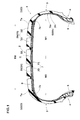
Fig. 1 is a cross sectional view of a pneumatic tire as an embodiment of the present invention. -
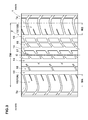
Fig. 2 is a partially cutaway, developed partial plan view of the pneumatic tire showing the tread portion and an arrangement of the belt cords and band cords. -
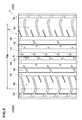
Fig. 3 is developed partial plan view of the pneumatic tire showing the tread portion -
Fig. 4 is developed partial plan view of a pneumatic tire as another embodiment of the present invention. -
Fig. 5 is developed partial plan view of a pneumatic tire as another embodiment of the present invention. - Embodiments of the present invention will now be described in detail in conjunction with accompanying drawings.
- According to the present invention, pneumatic tire 1 comprises a
tread portion 2, a pair of axially spacedbead portions 4 each with abead core 5 therein, a pair ofsidewall portions 3 extending between the tread edges Te and thebead portions 4, acarcass 6 extending between thebead portions 4, abelt 7 disposed radially outside thecarcass 6 in thetread portion 2, and aband 9 disposed radially outside thebelt 7. - In the following embodiments, the pneumatic tire 1 is designed as a radial tire for passenger cars.
- The
carcass 6 is composed of at least oneply 6A of cords arranged radially at an angle in the range of from 70 to 90 degrees with respect to the tire equator C. Thecarcass ply 6A is extended between thebead portions 4 through thetread portion 2 andsidewall portions 3 and turned up around thebead core 5 in eachbead portion 4 from the axially inside to the axially outside of the tire to form a pair ofturnup portions 6b and amain portion 6a therebetween. In this example, thecarcass 6 is composed of asingle ply 6A of cords arranged radially at an angle of 90 degrees with respect to the tire equator C. For example, organic fiber cords, e.g. nylon, polyester, aromatic polyamide, rayon and the like can be used as the cords of thecarcass ply 6A. - The
belt 7 is composed of a radiallyinner ply 10 and a radiallyouter ply 11 disposed thereon. - As shown in
Fig. 2 , the radiallyinner belt ply 10 is composed ofcords 10c laid parallel with each other. The radiallyouter belt ply 11 is composed ofcords 11c laid parallel with each other so as to cross thebelt cords 10c. For example, steel cords can be used as thebelt cords edges 7e of thebelt 7 in the tire axial direction (in this example, those of the widest ply 10) are positioned axially outside the respective tread edges Te. - The
band 9 is composed of a plurality ofplies 12 each composed of at least onecord 12c whose angle with respect to the tire circumferential direction is not more than 5 degrees. In this example, the band cord(s) 12c embedded in topping rubber in the form of a tape or a narrow width strip, is spirally wound on the outside of thebelt 7 to form theband ply 12. As to theband cords 12c, organic fiber cords, e.g. nylon, rayon, PEN, aramid and the like can be used. - In each of the band plies, the cord count of the band cord(s) 12c is 35 to 45 per 5cm width.
- The
band 9 comprises afirst part 20 composed of the first band cord 20c(12c) having a first modulus M1, and asecond part 30 composed of thesecond band cord 30c(12c) having a second modulus M2 higher than the first modulus M1. Thefirst part 20 is positioned on the inboard side of the tire equator C. Thesecond part 30 is positioned on the outboard side of the tire equator C. - In this invention, the term "modulus" of the cord means the tensile strength (centinewton per dtex) of the cord.
- Increasing the modulus of the band cord has greater effect on the improvement in the high-speed durability than increasing the number of laminated band plies of a low modulus cord. According to the present invention, therefore, in order to improve the high-speed durability, the
band 9 is constructed so that its binding force is increased in the outboard area of thetread portion 2 subjected to relatively high ground pressure during high speed cornering. The majority of passenger cars have tires mounted with negative camber, therefore, during straight running, such tire is relatively increased in the ground pressure in the inboard area of thetread portion 2. Therefore, even if the modulus of the band cord is increased in the outboard area of thetread portion 2, it will be hardly exert a negative effect on the ride comfort during straight running. - Preferably, the ratio M2/M1 of the second modulus M2 to the first modulus M1 is set in a range of not less than 1.2, more preferably not less than 2.0, but not more than 7.0, more preferably not more than 6.0.
- If the ratio M2/M1 is less than 1.2, there is a possibility that the high-speed durability can not be fully improved. If the ratio M2/M1 is more than 7.0, a large difference in the rigidity occurs in the
tread portion 2, and there is a possibility that the durability of the tire is decreased. - Preferably, the second modulus M2 is set in a range of not less than 42.0 centinewton/dtex, more preferably not less than 55.0 centinewton/dtex, but not more than 77.0 centinewton/dtex, more preferably not more than 65.0 centinewton/dtex in order that the
second part 30 exerts excellent high-speed durability without sacrificing the ride comfort. - Preferably, the first modulus M1 is set in a range of not less than 17.0 centinewton/dtex, more preferably not less than 18.5 centinewton/dtex, but not more than 21.5 centinewton/dtex, more preferably not more than 20.0 centinewton/dtex. If the first modulus M1 is less than 17.0 centinewton/dtex, there is a possibility that the high-speed durability and the steering stability are deteriorated. If the first modulus M1 is more than 21.5 centinewton/dtex, there is a possibility that the ride comfort is deteriorated.
- The number of the laminated band plies in the
first part 20 is more than the number of the laminated band plies or single band ply in thesecond part 30. Preferably, the difference therebetween is 1 or 2. - Increasing the number of laminated band plies of a low modulus cord exerts less negative effect on the ride comfort in comparison with increasing the modulus of the band cord. As explained above, during straight running, the ground pressure in the inboard area of the
tread portion 2 is relatively increased, therefore, the increasing of the number of band plies in thefirst part 20 can improve the high-speed durability, without sacrificing the ride comfort. - If the difference in the band ply number is more than 2, a large difference in the rigidity occurs in the
tread portion 2, and there is a possibility that the ride comfort and the steering stability are deteriorated. - In this example, the
first part 20 is formed by two laminated band plies, namely, a radially innerfirst band ply 23 and a wider radially outer first band ply 22 disposed thereon. The radially outer first band ply 22 extends from the tire equator C to a position beyond theinboard edge 7i of thebelt 7 to cover one half of thebelt 7 on the inboard side of the tire equator C. - The radially inner first band ply 23 covers the
inboard edge 10i of the radially inner belt ply 10 and theinboard edge 11i of the radially outer belt ply 11. - Preferably, the axial width W5 of the radially inner first band ply 23 is set in a range of not less than 0.20 times, more preferably not less than 0.23 times, but not more than 0.30 times, more preferably not more than 0.27 times the tread width TW in order that the radially inner first band ply 23 can prevent damage starting from the edges of the radially inner belt ply 10 and radially outer belt ply 11, without excessively increasing the rigidity in the inboard area of the
tread portion 2. - On the other hand, the
second part 30 in this example is formed by a second band ply 31 only. - The second band ply 31 extends from the tire equator C to a position beyond the outboard edge 7o of the
belt 7 to cover the other one half of thebelt 7 on the outboard side of the tire equator C. - In this example, the
boundary 33 between thefirst part 20 and thesecond part 30 is positioned at the tire equator C. But, it may be deviated away from the tire equator C toward the inboard side or outboard side thereof. - Further, the
first part 20 and thesecond part 30 may be spaced apart from each other in the vicinity of the tire equator C. In either case, it is preferable that the axially inner edges of thefirst part 20 and thesecond part 30 are positioned in the vicinity of the tire equator. For example, the axial distance of each of the axially inner edges from the tire equator is less than about 5 % of the tread width TW, or within the axial width of a center rib or block if such tread element is provided. - If the axial width W2 of the
second part 30 is more than the axial width W1 of thefirst part 20, as the amount of the band cord having a relatively high modulus is increased, there is a possibility that the ride comfort is deteriorated. Therefore, the axial width W2 may be less than the axial width W1 as shown inFig. 1 . In view of the ride comfort, it is preferable that the ratio W2/W1 of the axial width W2 to the axial width W1 is not more than 0.90, more preferably not more than 0.70. But, if the ratio W2/W1 is decreased, there is a possibility that the durability of thetread portion 2 in the outboard area is decreased. Therefore, the ratio W2/W1 is preferably not less than 0.20, more preferably not less than 0.50. - It is preferable that the cord count of the or each band ply in the
second part 30 is the same as the cord count of the or each band ply in thefirst part 20 in order not to deteriorate the tire uniformity, and also in order to improve the production efficiency of the tire. - By the way, the
tread portion 2 is provided with circumferentially continuously extending main grooves which are, as shown inFig. 3 , a pair of crownmain grooves 14 disposed one on each side of the tire equator C, and a pair of axially outermost shouldermain grooves 13 disposed axially outside the respective crownmain grooves 14. Therefore, thetread portion 2 is divided into a pair ofshoulder land portions 15 axially outside the shouldermain grooves 13, a pair ofmiddle land portions 16 between the shouldermain grooves 13 and the crownmain grooves 14, and acentral land portion 17 between the crownmain grooves 14. - If the pattern rigidity in the outboard area of the
tread portion 2 is high, the high-speed durability may be improved. Therefore, the land ratio L2 of one half of thetread portion 2 on the outboard side of the tire equator C is set to be larger than the land ratio L1 of the other one half of thetread portion 2 on the inboard side of the tire equator C. Here, the land ratio is the ratio of the ground contacting area of the part concerned to the overall area of the part concerned. Preferably, the ratio L2/L1 of the land ratio L2 to the land ratio L1 is set in a range of not less than 1.03, more preferably not less than 1.05, but not more than 1.20, more preferably not more than 1.15. - If the ratio L2/L1 is less than 1.03, there is a possibility that the above-mentioned advantageous effects can not be obtained. If the ratio L2/L1 is more than 1.15, there is a possibility that uneven wear occurs in the inboard area of the
tread portion 2. - For similar reasons, it is preferable that the axial width W4 of the outboard
shoulder land portion 15A is more than the axial width W3 of the inboardshoulder land portion 15B. The ratio W4/W3 of the width W4 to the width W3 is Preferably set in a range of not less than 1.05, more preferably not less than 1.07, but not more than 1.25, more preferably not more than 1.20 in order that theshoulder land portions 15 can exert excellent high-speed durability without sacrificing the ride comfort. - Thus, the tread pattern is also asymmetric about the tire equator C.
- Pneumatic tires of size 205/55R16 (rim size 16x6.5JJ) having the internal structure shown in
Fig. 1 and specifications shown in Table 1 were prepared and tested for the ride comfort and high-speed durability. In the tests, the tire pressure was 230 kPa. - The test tires were installed on the four wheels of a test car (2000 cc front-wheel-drive passenger car), and the test driver evaluated the ride comfort during the test car was running on a tire test road. The results are shown in Table 1, wherein the larger the value, the better the ride comfort.
- In a test circuit course, the test car was run until the outboard half of the tread portion was damaged, and the number of laps was counted. The results are indicated in Table 1 by an index based on Ref.1 being 100, wherein the larger the index, the better the high-speed durability.
- Using a tire test drum, the test tire mounted with a camber angle of -3 degrees was run until the inboard half of the tread portion was damaged to obtain the accumulated running distance. The results are indicated in Table 1 by an index based on Ref.1 being 100, wherein the larger the index, the better the high-speed durability.
- From the test results, it was confirmed that the tires according to the present invention can be improved in the ride comfort and high-speed durability.
Table 1 Tire Ref.1 Ref.2 Ref.3 Ref.4 Ex.1 Ex.2 Ex.3 Ex.4 Ex.5 Ex.6 Ex.7 Ex.8 Ex.9 Ex.10 Ex.11 Ex.12 tread pattern (Fig. No.) 5 5 5 4 5 5 5 5 5 5 5 5 3 3 3 3 first part number of band ply 2 1 1 2 2 2 2 2 2 2 2 2 2 2 2 2 band cord material nylon nylon PEN nylon nylon nylon nylon nylon nylon nylon nylon nylon nylon nylon nylon nylon band cord modulus M1 17.0 17.0 42.0 17.0 17.0 17.0 17.0 17.0 17.0 17.0 17.0 17.0 17.0 17.0 17.0 17.0 second part number of band ply 2 1 1 2 1 1 1 1 1 1 1 1 1 1 1 1 band cord material nylon nylon PEN nylon nylon nylon PEN aramid nylon nylon PEN aramid nylon nylon PEN aramid band cord modulus M2 17.0 17.0 42.0 17.0 20.0 21.5 42.0 77.0 20.0 21.5 42.0 77.0 20.0 21.5 42.0 77.0 modulus ratio M2/M1 1.00 1.00 1.00 1.00 1.18 1.26 2.47 4.53 1.18 1.26 2.47 4.53 1.18 1.26 2.47 4.53 width ratio W2/W1 1.0 1.0 1.0 1.0 1.0 1.0 1.0 1.0 0.65 0.65 0.65 0.65 0.65 0.65 0.65 0.65 width ratio W4/W3 1.0 1.0 1.0 1.0 1.0 1.0 1.0 1.0 1.0 1.0 1.0 1.0 1.09 1.09 1.09 1.09 ride comfort 60 70 50 70 67 67 60 55 70 70 65 60 80 80 75 70 high-speed durability outboard 100 80 120 90 107 112 120 130 107 110 120 130 107 110 120 130 inboard 100 90 100 100 100 100 100 100 100 100 100 100 100 100 100 100
Claims (8)
- A pneumatic tire whose mounting location on a vehicle is specified and which comprises:a carcass extending between bead portions through a tread portion and sidewall portions,a belt disposed radially outside the carcass in the tread portion, and composed of belt cords laid at an angle of from 15 to 40 degrees with respect to the tire circumferential direction, anda band disposed radially outside the belt, and composed of first and second band cords laid at an angle of not more than 5 degrees with respect to the tire circumferential direction, whereinthe band comprises an inboard first part composed of the first band cord having a first modulus M1 and to be positioned close to the center of a vehicle body, andan outboard second part composed of the second band cord having a second modulus M2 more than the first modulus M1 and to be positioned away from the center of the vehicle body, andthe number of laminated plies of the band in the inboard first part is more than the number of laminated plies or ply of the band in the outboard second part.
- The pneumatic tire according to claim 1, wherein
the ratio M2/M1 of the second modulus M2 to the first modulus M1 is 1.2 to 7.0. - the pneumatic tire according to claim 1 or 2, wherein
the second modulus M2 is 42.0 to 77.0 centinewton/dtex, and the first modulus M1 is 17.0 to 21.5 centinewton/dtex. - The pneumatic tire according to claim 1, 2 or 3, wherein
the second band cord is an aramid fiber cord, and the first band cord is a nylon fiber cord. - The pneumatic tire according to claim 1, 2, 3 or 4, wherein
the band ply number in the inboard first part is 2, and the band ply number in the outboard second part is 1. - The pneumatic tire according to any one of claims 1-5, wherein
the axial width W2 of the outboard second part is less than the axial width W1 of the inboard first part. - The pneumatic tire according to any one of claims 1-6, wherein
the cord count of the or each band ply in the outboard second part is the same as the cord count of the or each band ply in the inboard first part. - The pneumatic tire according to any one of claims 1-7, wherein
the land ratio of one half of the tread portion on the outboard side of the tire equator is more than the land ratio of the other one half of the tread portion on the inboard side of the tire equator,
the tread portion is provided on each side of the tire equator with an axially outermost, circumferentially continuously extending main groove so as to define a shoulder land portion axially outside the main groove, and
the axial width W4 of the outboard shoulder land portion is more than the axial width W3 of the inboard shoulder land portion.
Applications Claiming Priority (1)
| Application Number | Priority Date | Filing Date | Title |
|---|---|---|---|
| JP2013049486A JP5756486B2 (en) | 2013-03-12 | 2013-03-12 | Pneumatic tire |
Publications (3)
| Publication Number | Publication Date |
|---|---|
| EP2777949A2 true EP2777949A2 (en) | 2014-09-17 |
| EP2777949A3 EP2777949A3 (en) | 2017-03-22 |
| EP2777949B1 EP2777949B1 (en) | 2018-09-19 |
Family
ID=50150611
Family Applications (1)
| Application Number | Title | Priority Date | Filing Date |
|---|---|---|---|
| EP14155889.0A Active EP2777949B1 (en) | 2013-03-12 | 2014-02-20 | Pneumatic tire |
Country Status (4)
| Country | Link |
|---|---|
| US (1) | US9604501B2 (en) |
| EP (1) | EP2777949B1 (en) |
| JP (1) | JP5756486B2 (en) |
| CN (1) | CN104044403B (en) |
Cited By (6)
| Publication number | Priority date | Publication date | Assignee | Title |
|---|---|---|---|---|
| CN106394132A (en) * | 2015-07-29 | 2017-02-15 | 东洋橡胶工业株式会社 | Pneumatic tire and method for manufacturing thereof |
| EP3162593A1 (en) * | 2015-10-26 | 2017-05-03 | Sumitomo Rubber Industries Limited | Tire |
| WO2018207112A1 (en) * | 2017-05-12 | 2018-11-15 | Pirelli Tyre S.P.A. | Tyre for vehicle wheels |
| CN109515069A (en) * | 2017-09-19 | 2019-03-26 | 住友橡胶工业株式会社 | Tire |
| EP3461657A1 (en) * | 2017-09-19 | 2019-04-03 | Sumitomo Rubber Industries, Ltd. | Tire |
| US11325422B2 (en) * | 2018-07-12 | 2022-05-10 | Sumitomo Rubber Industries, Ltd. | Tyre |
Families Citing this family (13)
| Publication number | Priority date | Publication date | Assignee | Title |
|---|---|---|---|---|
| EP3064376B1 (en) * | 2013-10-29 | 2018-10-24 | Bridgestone Corporation | Tire |
| DE102013226443A1 (en) * | 2013-12-18 | 2015-06-18 | Continental Reifen Deutschland Gmbh | Vehicle tires |
| DE102013226442A1 (en) * | 2013-12-18 | 2015-06-18 | Continental Reifen Deutschland Gmbh | Vehicle tires |
| JP6030623B2 (en) * | 2014-11-26 | 2016-11-24 | 住友ゴム工業株式会社 | Pneumatic tire |
| CN104527330A (en) * | 2014-12-09 | 2015-04-22 | 杭州朝阳橡胶有限公司 | Single-layer high elongation steel wire reinforced belt ply structure and design method thereof |
| US10723177B2 (en) | 2015-08-31 | 2020-07-28 | The Goodyear Tire & Rubber Company | Reduced weight aircraft tire |
| US11827064B2 (en) | 2015-08-31 | 2023-11-28 | The Goodyear Tire & Rubber Company | Reduced weight aircraft tire |
| JP6710068B2 (en) * | 2016-03-08 | 2020-06-17 | 株式会社ブリヂストン | Pneumatic tire |
| JP6807263B2 (en) * | 2016-03-30 | 2021-01-06 | 株式会社ブリヂストン | Pneumatic tires |
| JP6935213B2 (en) * | 2016-03-30 | 2021-09-15 | 株式会社ブリヂストン | Pneumatic tires |
| JP6943107B2 (en) * | 2017-09-19 | 2021-09-29 | 住友ゴム工業株式会社 | tire |
| JP2023001588A (en) * | 2021-06-21 | 2023-01-06 | 株式会社ブリヂストン | tire |
| JP2024023080A (en) * | 2022-08-08 | 2024-02-21 | 株式会社ブリヂストン | Pneumatic radial tire for passenger vehicle |
Family Cites Families (8)
| Publication number | Priority date | Publication date | Assignee | Title |
|---|---|---|---|---|
| DE4209817A1 (en) * | 1992-03-26 | 1993-09-30 | Uniroyal Englebert Gmbh | Radial pneumatic tyre - has cover fabric over running belt layer with high modulus near middle and lower modulus near shoulder |
| DE4240278A1 (en) * | 1992-12-01 | 1994-06-09 | Uniroyal Englebert Gmbh | Pneumatic vehicle tires with asymmetrical belt properties |
| JP3066332B2 (en) * | 1996-12-25 | 2000-07-17 | 住友ゴム工業株式会社 | Pneumatic radial tire |
| DE20216992U1 (en) * | 2002-11-04 | 2003-01-16 | Goodyear Dunlop Tires Germany GmbH, 63450 Hanau | Pneumatic vehicle tires, in particular summer tires for passenger cars |
| JP4748522B2 (en) * | 2006-06-14 | 2011-08-17 | 東洋ゴム工業株式会社 | Pneumatic tire |
| JP2008126716A (en) * | 2006-11-17 | 2008-06-05 | Bridgestone Corp | Pneumatic radial tire |
| JP4295795B2 (en) | 2007-12-07 | 2009-07-15 | 住友ゴム工業株式会社 | Pneumatic tire |
| DE102010016550A1 (en) * | 2010-04-21 | 2011-10-27 | Continental Reifen Deutschland Gmbh | Vehicle tires |
-
2013
- 2013-03-12 JP JP2013049486A patent/JP5756486B2/en active Active
-
2014
- 2014-02-20 EP EP14155889.0A patent/EP2777949B1/en active Active
- 2014-03-04 CN CN201410077033.6A patent/CN104044403B/en active Active
- 2014-03-11 US US14/204,328 patent/US9604501B2/en active Active
Cited By (12)
| Publication number | Priority date | Publication date | Assignee | Title |
|---|---|---|---|---|
| CN106394132A (en) * | 2015-07-29 | 2017-02-15 | 东洋橡胶工业株式会社 | Pneumatic tire and method for manufacturing thereof |
| EP3162593A1 (en) * | 2015-10-26 | 2017-05-03 | Sumitomo Rubber Industries Limited | Tire |
| CN106985618A (en) * | 2015-10-26 | 2017-07-28 | 住友橡胶工业株式会社 | Tire |
| US10363781B2 (en) | 2015-10-26 | 2019-07-30 | Sumitomo Rubber Industries, Ltd. | Tire |
| CN106985618B (en) * | 2015-10-26 | 2020-03-06 | 住友橡胶工业株式会社 | Tyre for vehicle wheels |
| WO2018207112A1 (en) * | 2017-05-12 | 2018-11-15 | Pirelli Tyre S.P.A. | Tyre for vehicle wheels |
| CN110891800A (en) * | 2017-05-12 | 2020-03-17 | 倍耐力轮胎股份公司 | Tyre for vehicle wheels |
| CN109515069A (en) * | 2017-09-19 | 2019-03-26 | 住友橡胶工业株式会社 | Tire |
| EP3461657A1 (en) * | 2017-09-19 | 2019-04-03 | Sumitomo Rubber Industries, Ltd. | Tire |
| US11135877B2 (en) | 2017-09-19 | 2021-10-05 | Sumitomo Rubber Industries, Ltd. | Tire |
| CN109515069B (en) * | 2017-09-19 | 2022-04-26 | 住友橡胶工业株式会社 | Tyre for vehicle wheels |
| US11325422B2 (en) * | 2018-07-12 | 2022-05-10 | Sumitomo Rubber Industries, Ltd. | Tyre |
Also Published As
| Publication number | Publication date |
|---|---|
| CN104044403B (en) | 2017-08-25 |
| EP2777949B1 (en) | 2018-09-19 |
| JP2014172582A (en) | 2014-09-22 |
| CN104044403A (en) | 2014-09-17 |
| JP5756486B2 (en) | 2015-07-29 |
| US9604501B2 (en) | 2017-03-28 |
| EP2777949A3 (en) | 2017-03-22 |
| US20140261952A1 (en) | 2014-09-18 |
Similar Documents
| Publication | Publication Date | Title |
|---|---|---|
| EP2777949B1 (en) | Pneumatic tire | |
| EP2716477B1 (en) | Pneumatic tire | |
| EP2660078B1 (en) | Pneumatic tire | |
| EP2135752B1 (en) | Motorcycle tire | |
| EP1440822B1 (en) | Pneumatic tire | |
| US7036541B2 (en) | Pneumatic tire | |
| US10105992B2 (en) | Pneumatic tire | |
| US11207927B2 (en) | Pneumatic tire | |
| EP2743099B9 (en) | Motorcycle tire | |
| US9340072B2 (en) | Motorcycle tire | |
| US11548323B2 (en) | Pneumatic tire | |
| EP3305551B1 (en) | Reinforcement member for tires, and tire using same | |
| EP3069901A1 (en) | Motorcycle tire | |
| EP2261060A2 (en) | Motorcycle tire | |
| EP3424752B1 (en) | Pneumatic tire | |
| EP3059100B1 (en) | Pneumatic tire | |
| EP4079543B1 (en) | Tire | |
| JP2008195360A (en) | Pneumatic tire | |
| JP6132632B2 (en) | Pneumatic tire | |
| US10940720B2 (en) | Tire for motorcycles | |
| US11524527B2 (en) | Pneumatic tire |
Legal Events
| Date | Code | Title | Description |
|---|---|---|---|
| PUAI | Public reference made under article 153(3) epc to a published international application that has entered the european phase |
Free format text: ORIGINAL CODE: 0009012 |
|
| 17P | Request for examination filed |
Effective date: 20140220 |
|
| AK | Designated contracting states |
Kind code of ref document: A2 Designated state(s): AL AT BE BG CH CY CZ DE DK EE ES FI FR GB GR HR HU IE IS IT LI LT LU LV MC MK MT NL NO PL PT RO RS SE SI SK SM TR |
|
| AX | Request for extension of the european patent |
Extension state: BA ME |
|
| PUAL | Search report despatched |
Free format text: ORIGINAL CODE: 0009013 |
|
| AK | Designated contracting states |
Kind code of ref document: A3 Designated state(s): AL AT BE BG CH CY CZ DE DK EE ES FI FR GB GR HR HU IE IS IT LI LT LU LV MC MK MT NL NO PL PT RO RS SE SI SK SM TR |
|
| AX | Request for extension of the european patent |
Extension state: BA ME |
|
| RIC1 | Information provided on ipc code assigned before grant |
Ipc: B60C 11/03 20060101ALI20170215BHEP Ipc: B60C 9/30 20060101ALI20170215BHEP Ipc: B60C 9/22 20060101ALI20170215BHEP Ipc: B60C 9/20 20060101AFI20170215BHEP |
|
| STAA | Information on the status of an ep patent application or granted ep patent |
Free format text: STATUS: REQUEST FOR EXAMINATION WAS MADE |
|
| R17P | Request for examination filed (corrected) |
Effective date: 20170906 |
|
| RBV | Designated contracting states (corrected) |
Designated state(s): AL AT BE BG CH CY CZ DE DK EE ES FI FR GB GR HR HU IE IS IT LI LT LU LV MC MK MT NL NO PL PT RO RS SE SI SK SM TR |
|
| RIC1 | Information provided on ipc code assigned before grant |
Ipc: B60C 9/20 20060101AFI20180205BHEP Ipc: B60C 9/30 20060101ALI20180205BHEP Ipc: B60C 9/22 20060101ALI20180205BHEP Ipc: B60C 11/03 20060101ALI20180205BHEP |
|
| GRAP | Despatch of communication of intention to grant a patent |
Free format text: ORIGINAL CODE: EPIDOSNIGR1 |
|
| STAA | Information on the status of an ep patent application or granted ep patent |
Free format text: STATUS: GRANT OF PATENT IS INTENDED |
|
| INTG | Intention to grant announced |
Effective date: 20180405 |
|
| GRAS | Grant fee paid |
Free format text: ORIGINAL CODE: EPIDOSNIGR3 |
|
| GRAA | (expected) grant |
Free format text: ORIGINAL CODE: 0009210 |
|
| STAA | Information on the status of an ep patent application or granted ep patent |
Free format text: STATUS: THE PATENT HAS BEEN GRANTED |
|
| AK | Designated contracting states |
Kind code of ref document: B1 Designated state(s): AL AT BE BG CH CY CZ DE DK EE ES FI FR GB GR HR HU IE IS IT LI LT LU LV MC MK MT NL NO PL PT RO RS SE SI SK SM TR |
|
| REG | Reference to a national code |
Ref country code: GB Ref legal event code: FG4D |
|
| REG | Reference to a national code |
Ref country code: CH Ref legal event code: EP |
|
| REG | Reference to a national code |
Ref country code: AT Ref legal event code: REF Ref document number: 1042810 Country of ref document: AT Kind code of ref document: T Effective date: 20181015 |
|
| REG | Reference to a national code |
Ref country code: IE Ref legal event code: FG4D |
|
| REG | Reference to a national code |
Ref country code: DE Ref legal event code: R096 Ref document number: 602014032406 Country of ref document: DE |
|
| REG | Reference to a national code |
Ref country code: NL Ref legal event code: MP Effective date: 20180919 |
|
| PG25 | Lapsed in a contracting state [announced via postgrant information from national office to epo] |
Ref country code: FI Free format text: LAPSE BECAUSE OF FAILURE TO SUBMIT A TRANSLATION OF THE DESCRIPTION OR TO PAY THE FEE WITHIN THE PRESCRIBED TIME-LIMIT Effective date: 20180919 Ref country code: SE Free format text: LAPSE BECAUSE OF FAILURE TO SUBMIT A TRANSLATION OF THE DESCRIPTION OR TO PAY THE FEE WITHIN THE PRESCRIBED TIME-LIMIT Effective date: 20180919 Ref country code: RS Free format text: LAPSE BECAUSE OF FAILURE TO SUBMIT A TRANSLATION OF THE DESCRIPTION OR TO PAY THE FEE WITHIN THE PRESCRIBED TIME-LIMIT Effective date: 20180919 Ref country code: NO Free format text: LAPSE BECAUSE OF FAILURE TO SUBMIT A TRANSLATION OF THE DESCRIPTION OR TO PAY THE FEE WITHIN THE PRESCRIBED TIME-LIMIT Effective date: 20181219 Ref country code: GR Free format text: LAPSE BECAUSE OF FAILURE TO SUBMIT A TRANSLATION OF THE DESCRIPTION OR TO PAY THE FEE WITHIN THE PRESCRIBED TIME-LIMIT Effective date: 20181220 Ref country code: LT Free format text: LAPSE BECAUSE OF FAILURE TO SUBMIT A TRANSLATION OF THE DESCRIPTION OR TO PAY THE FEE WITHIN THE PRESCRIBED TIME-LIMIT Effective date: 20180919 Ref country code: BG Free format text: LAPSE BECAUSE OF FAILURE TO SUBMIT A TRANSLATION OF THE DESCRIPTION OR TO PAY THE FEE WITHIN THE PRESCRIBED TIME-LIMIT Effective date: 20181219 |
|
| REG | Reference to a national code |
Ref country code: LT Ref legal event code: MG4D |
|
| PG25 | Lapsed in a contracting state [announced via postgrant information from national office to epo] |
Ref country code: AL Free format text: LAPSE BECAUSE OF FAILURE TO SUBMIT A TRANSLATION OF THE DESCRIPTION OR TO PAY THE FEE WITHIN THE PRESCRIBED TIME-LIMIT Effective date: 20180919 Ref country code: HR Free format text: LAPSE BECAUSE OF FAILURE TO SUBMIT A TRANSLATION OF THE DESCRIPTION OR TO PAY THE FEE WITHIN THE PRESCRIBED TIME-LIMIT Effective date: 20180919 Ref country code: LV Free format text: LAPSE BECAUSE OF FAILURE TO SUBMIT A TRANSLATION OF THE DESCRIPTION OR TO PAY THE FEE WITHIN THE PRESCRIBED TIME-LIMIT Effective date: 20180919 |
|
| REG | Reference to a national code |
Ref country code: AT Ref legal event code: MK05 Ref document number: 1042810 Country of ref document: AT Kind code of ref document: T Effective date: 20180919 |
|
| PG25 | Lapsed in a contracting state [announced via postgrant information from national office to epo] |
Ref country code: AT Free format text: LAPSE BECAUSE OF FAILURE TO SUBMIT A TRANSLATION OF THE DESCRIPTION OR TO PAY THE FEE WITHIN THE PRESCRIBED TIME-LIMIT Effective date: 20180919 Ref country code: IS Free format text: LAPSE BECAUSE OF FAILURE TO SUBMIT A TRANSLATION OF THE DESCRIPTION OR TO PAY THE FEE WITHIN THE PRESCRIBED TIME-LIMIT Effective date: 20190119 Ref country code: PL Free format text: LAPSE BECAUSE OF FAILURE TO SUBMIT A TRANSLATION OF THE DESCRIPTION OR TO PAY THE FEE WITHIN THE PRESCRIBED TIME-LIMIT Effective date: 20180919 Ref country code: NL Free format text: LAPSE BECAUSE OF FAILURE TO SUBMIT A TRANSLATION OF THE DESCRIPTION OR TO PAY THE FEE WITHIN THE PRESCRIBED TIME-LIMIT Effective date: 20180919 Ref country code: CZ Free format text: LAPSE BECAUSE OF FAILURE TO SUBMIT A TRANSLATION OF THE DESCRIPTION OR TO PAY THE FEE WITHIN THE PRESCRIBED TIME-LIMIT Effective date: 20180919 Ref country code: ES Free format text: LAPSE BECAUSE OF FAILURE TO SUBMIT A TRANSLATION OF THE DESCRIPTION OR TO PAY THE FEE WITHIN THE PRESCRIBED TIME-LIMIT Effective date: 20180919 Ref country code: RO Free format text: LAPSE BECAUSE OF FAILURE TO SUBMIT A TRANSLATION OF THE DESCRIPTION OR TO PAY THE FEE WITHIN THE PRESCRIBED TIME-LIMIT Effective date: 20180919 Ref country code: IT Free format text: LAPSE BECAUSE OF FAILURE TO SUBMIT A TRANSLATION OF THE DESCRIPTION OR TO PAY THE FEE WITHIN THE PRESCRIBED TIME-LIMIT Effective date: 20180919 Ref country code: EE Free format text: LAPSE BECAUSE OF FAILURE TO SUBMIT A TRANSLATION OF THE DESCRIPTION OR TO PAY THE FEE WITHIN THE PRESCRIBED TIME-LIMIT Effective date: 20180919 |
|
| PG25 | Lapsed in a contracting state [announced via postgrant information from national office to epo] |
Ref country code: PT Free format text: LAPSE BECAUSE OF FAILURE TO SUBMIT A TRANSLATION OF THE DESCRIPTION OR TO PAY THE FEE WITHIN THE PRESCRIBED TIME-LIMIT Effective date: 20190119 Ref country code: SM Free format text: LAPSE BECAUSE OF FAILURE TO SUBMIT A TRANSLATION OF THE DESCRIPTION OR TO PAY THE FEE WITHIN THE PRESCRIBED TIME-LIMIT Effective date: 20180919 Ref country code: SK Free format text: LAPSE BECAUSE OF FAILURE TO SUBMIT A TRANSLATION OF THE DESCRIPTION OR TO PAY THE FEE WITHIN THE PRESCRIBED TIME-LIMIT Effective date: 20180919 |
|
| REG | Reference to a national code |
Ref country code: DE Ref legal event code: R097 Ref document number: 602014032406 Country of ref document: DE |
|
| PLBE | No opposition filed within time limit |
Free format text: ORIGINAL CODE: 0009261 |
|
| STAA | Information on the status of an ep patent application or granted ep patent |
Free format text: STATUS: NO OPPOSITION FILED WITHIN TIME LIMIT |
|
| PG25 | Lapsed in a contracting state [announced via postgrant information from national office to epo] |
Ref country code: DK Free format text: LAPSE BECAUSE OF FAILURE TO SUBMIT A TRANSLATION OF THE DESCRIPTION OR TO PAY THE FEE WITHIN THE PRESCRIBED TIME-LIMIT Effective date: 20180919 |
|
| 26N | No opposition filed |
Effective date: 20190620 |
|
| REG | Reference to a national code |
Ref country code: CH Ref legal event code: PL |
|
| GBPC | Gb: european patent ceased through non-payment of renewal fee |
Effective date: 20190220 |
|
| PG25 | Lapsed in a contracting state [announced via postgrant information from national office to epo] |
Ref country code: SI Free format text: LAPSE BECAUSE OF FAILURE TO SUBMIT A TRANSLATION OF THE DESCRIPTION OR TO PAY THE FEE WITHIN THE PRESCRIBED TIME-LIMIT Effective date: 20180919 Ref country code: LU Free format text: LAPSE BECAUSE OF NON-PAYMENT OF DUE FEES Effective date: 20190220 Ref country code: MC Free format text: LAPSE BECAUSE OF FAILURE TO SUBMIT A TRANSLATION OF THE DESCRIPTION OR TO PAY THE FEE WITHIN THE PRESCRIBED TIME-LIMIT Effective date: 20180919 |
|
| REG | Reference to a national code |
Ref country code: BE Ref legal event code: MM Effective date: 20190228 |
|
| REG | Reference to a national code |
Ref country code: IE Ref legal event code: MM4A |
|
| PG25 | Lapsed in a contracting state [announced via postgrant information from national office to epo] |
Ref country code: LI Free format text: LAPSE BECAUSE OF NON-PAYMENT OF DUE FEES Effective date: 20190228 Ref country code: CH Free format text: LAPSE BECAUSE OF NON-PAYMENT OF DUE FEES Effective date: 20190228 |
|
| PG25 | Lapsed in a contracting state [announced via postgrant information from national office to epo] |
Ref country code: IE Free format text: LAPSE BECAUSE OF NON-PAYMENT OF DUE FEES Effective date: 20190220 Ref country code: GB Free format text: LAPSE BECAUSE OF NON-PAYMENT OF DUE FEES Effective date: 20190220 |
|
| PG25 | Lapsed in a contracting state [announced via postgrant information from national office to epo] |
Ref country code: BE Free format text: LAPSE BECAUSE OF NON-PAYMENT OF DUE FEES Effective date: 20190228 |
|
| PG25 | Lapsed in a contracting state [announced via postgrant information from national office to epo] |
Ref country code: TR Free format text: LAPSE BECAUSE OF FAILURE TO SUBMIT A TRANSLATION OF THE DESCRIPTION OR TO PAY THE FEE WITHIN THE PRESCRIBED TIME-LIMIT Effective date: 20180919 |
|
| PG25 | Lapsed in a contracting state [announced via postgrant information from national office to epo] |
Ref country code: MT Free format text: LAPSE BECAUSE OF NON-PAYMENT OF DUE FEES Effective date: 20190220 |
|
| PG25 | Lapsed in a contracting state [announced via postgrant information from national office to epo] |
Ref country code: CY Free format text: LAPSE BECAUSE OF FAILURE TO SUBMIT A TRANSLATION OF THE DESCRIPTION OR TO PAY THE FEE WITHIN THE PRESCRIBED TIME-LIMIT Effective date: 20180919 |
|
| PG25 | Lapsed in a contracting state [announced via postgrant information from national office to epo] |
Ref country code: HU Free format text: LAPSE BECAUSE OF FAILURE TO SUBMIT A TRANSLATION OF THE DESCRIPTION OR TO PAY THE FEE WITHIN THE PRESCRIBED TIME-LIMIT; INVALID AB INITIO Effective date: 20140220 |
|
| PG25 | Lapsed in a contracting state [announced via postgrant information from national office to epo] |
Ref country code: MK Free format text: LAPSE BECAUSE OF FAILURE TO SUBMIT A TRANSLATION OF THE DESCRIPTION OR TO PAY THE FEE WITHIN THE PRESCRIBED TIME-LIMIT Effective date: 20180919 |
|
| PGFP | Annual fee paid to national office [announced via postgrant information from national office to epo] |
Ref country code: DE Payment date: 20231228 Year of fee payment: 11 |
|
| PGFP | Annual fee paid to national office [announced via postgrant information from national office to epo] |
Ref country code: FR Payment date: 20240103 Year of fee payment: 11 |