EP2777583A1 - Instrument zur Gefäßfusion und Trennung - Google Patents
Instrument zur Gefäßfusion und Trennung Download PDFInfo
- Publication number
- EP2777583A1 EP2777583A1 EP13159361.8A EP13159361A EP2777583A1 EP 2777583 A1 EP2777583 A1 EP 2777583A1 EP 13159361 A EP13159361 A EP 13159361A EP 2777583 A1 EP2777583 A1 EP 2777583A1
- Authority
- EP
- European Patent Office
- Prior art keywords
- knife
- instrument according
- insulator
- electrode surface
- drive element
- Prior art date
- Legal status (The legal status is an assumption and is not a legal conclusion. Google has not performed a legal analysis and makes no representation as to the accuracy of the status listed.)
- Granted
Links
- 238000000926 separation method Methods 0.000 title claims description 5
- 230000004927 fusion Effects 0.000 title claims description 4
- 239000002184 metal Substances 0.000 claims abstract description 8
- 239000004020 conductor Substances 0.000 claims abstract description 4
- 239000012212 insulator Substances 0.000 claims description 46
- 238000005520 cutting process Methods 0.000 claims description 32
- 241000446313 Lamella Species 0.000 claims description 2
- 230000002792 vascular Effects 0.000 claims description 2
- 239000007787 solid Substances 0.000 claims 1
- 238000005345 coagulation Methods 0.000 description 13
- 230000015271 coagulation Effects 0.000 description 13
- 239000000463 material Substances 0.000 description 8
- 230000005540 biological transmission Effects 0.000 description 7
- 210000004204 blood vessel Anatomy 0.000 description 5
- 241001465754 Metazoa Species 0.000 description 2
- 230000001154 acute effect Effects 0.000 description 2
- 230000001112 coagulating effect Effects 0.000 description 2
- 239000012530 fluid Substances 0.000 description 2
- 238000009413 insulation Methods 0.000 description 2
- 238000000034 method Methods 0.000 description 2
- 230000003071 parasitic effect Effects 0.000 description 2
- 229910001220 stainless steel Inorganic materials 0.000 description 2
- 239000010935 stainless steel Substances 0.000 description 2
- 241000511343 Chondrostoma nasus Species 0.000 description 1
- 229910000831 Steel Inorganic materials 0.000 description 1
- 230000035508 accumulation Effects 0.000 description 1
- 238000009825 accumulation Methods 0.000 description 1
- 230000004913 activation Effects 0.000 description 1
- 230000002411 adverse Effects 0.000 description 1
- 239000012620 biological material Substances 0.000 description 1
- 230000015572 biosynthetic process Effects 0.000 description 1
- 230000000295 complement effect Effects 0.000 description 1
- 230000001419 dependent effect Effects 0.000 description 1
- 238000010292 electrical insulation Methods 0.000 description 1
- 238000002674 endoscopic surgery Methods 0.000 description 1
- 238000002955 isolation Methods 0.000 description 1
- 230000002045 lasting effect Effects 0.000 description 1
- 238000004519 manufacturing process Methods 0.000 description 1
- 230000013011 mating Effects 0.000 description 1
- 239000012811 non-conductive material Substances 0.000 description 1
- 239000002504 physiological saline solution Substances 0.000 description 1
- 230000000630 rising effect Effects 0.000 description 1
- 238000004904 shortening Methods 0.000 description 1
- 210000002023 somite Anatomy 0.000 description 1
- 239000010959 steel Substances 0.000 description 1
- 229920001187 thermosetting polymer Polymers 0.000 description 1
Images

Classifications
-
- A—HUMAN NECESSITIES
- A61—MEDICAL OR VETERINARY SCIENCE; HYGIENE
- A61B—DIAGNOSIS; SURGERY; IDENTIFICATION
- A61B18/00—Surgical instruments, devices or methods for transferring non-mechanical forms of energy to or from the body
-
- A—HUMAN NECESSITIES
- A61—MEDICAL OR VETERINARY SCIENCE; HYGIENE
- A61B—DIAGNOSIS; SURGERY; IDENTIFICATION
- A61B18/00—Surgical instruments, devices or methods for transferring non-mechanical forms of energy to or from the body
- A61B18/04—Surgical instruments, devices or methods for transferring non-mechanical forms of energy to or from the body by heating
- A61B18/12—Surgical instruments, devices or methods for transferring non-mechanical forms of energy to or from the body by heating by passing a current through the tissue to be heated, e.g. high-frequency current
- A61B18/14—Probes or electrodes therefor
- A61B18/1442—Probes having pivoting end effectors, e.g. forceps
- A61B18/1445—Probes having pivoting end effectors, e.g. forceps at the distal end of a shaft, e.g. forceps or scissors at the end of a rigid rod
-
- A—HUMAN NECESSITIES
- A61—MEDICAL OR VETERINARY SCIENCE; HYGIENE
- A61B—DIAGNOSIS; SURGERY; IDENTIFICATION
- A61B18/00—Surgical instruments, devices or methods for transferring non-mechanical forms of energy to or from the body
- A61B2018/00571—Surgical instruments, devices or methods for transferring non-mechanical forms of energy to or from the body for achieving a particular surgical effect
- A61B2018/0063—Sealing
-
- A—HUMAN NECESSITIES
- A61—MEDICAL OR VETERINARY SCIENCE; HYGIENE
- A61B—DIAGNOSIS; SURGERY; IDENTIFICATION
- A61B18/00—Surgical instruments, devices or methods for transferring non-mechanical forms of energy to or from the body
- A61B18/04—Surgical instruments, devices or methods for transferring non-mechanical forms of energy to or from the body by heating
- A61B18/12—Surgical instruments, devices or methods for transferring non-mechanical forms of energy to or from the body by heating by passing a current through the tissue to be heated, e.g. high-frequency current
- A61B18/14—Probes or electrodes therefor
- A61B18/1442—Probes having pivoting end effectors, e.g. forceps
- A61B2018/1452—Probes having pivoting end effectors, e.g. forceps including means for cutting
- A61B2018/1455—Probes having pivoting end effectors, e.g. forceps including means for cutting having a moving blade for cutting tissue grasped by the jaws
Definitions
- the invention relates to an instrument for grasping, coagulating and severing tissue, in particular for clamping, closing and severing vessels, in particular blood vessels, on the living body of a human or animal patient.
- Instruments for closing and separating blood vessels are for example the DE 602 26 015 T2 refer to.
- such instruments have an elongated shaft extending away from a handle.
- a tool with two branches for clamping a blood vessel is arranged.
- a longitudinally displaceable knife is arranged there in order to be able to sever a grasped and coagulated vessel.
- the branches and the knife are to be operated via corresponding actuators on the handle.
- the branches are designed as electrodes and can be selectively supplied with current in order to heat the vessel clamped between them and to fuse the vessel walls by coagulation.
- the inventive measure also leads to the instrument in different environments, for example can also be used in accumulations of physiological saline or similar electrically conductive fluids.
- the isolation of the blade from the drive element prevents or reduces the possibility of parasitic current paths within the tool or shaft of the instrument, thus ensuring that the current to be applied to the biological tissue actually makes its way through the biological tissue. This ensures the desired intensity of the coagulation process.
- the energization of the branches can be made and / or continued when the blade is moved from its rest position to the active position. It is avoided that a short circuit between the branches or their electrodes occurs via the knife. It is prevented that electrical current is passed over the knife on the tissue.
- the electrical current is conducted from one electrode via the clamped tissue to the other electrode.
- This has a positive influence on the coagulation of the clamped tissue and also ensures that the user operates the knife prematurely.
- This is particularly conceivable in two-stage tool drives, in which an operating handle is used to close the branches on the first part of his way and to advance the knife on a second, last path. If the user unconsciously moves the hand lever too far in the direction of the operating position of the knife, it can be moved a little and thus take over at least part of the coagulation current.
- the insulation of the knife according to the invention avoids this possibility of error.
- the first electrode preferably has a knife sliding surface on which the knife can run along. In this way, an electrical contact between the first electrode and the knife, at least during the Severing the coagulated vessel. There may thus be a flow of current between the coagulated tissue and the knife, which may adversely affect coagulation.
- the insulation of the knife avoids this flow of current as well as damage to the knife or its cutting edge or tip by current flow.
- the knife may be associated with a vertical actuating mechanism to adjust the knife transversely depending on its longitudinal movement preferably perpendicular to this movement in order to float the tip of the knife and not only with the first electrode but with other edges, steps or the like, in To bring touch. This protects the knife and ensures its lasting sharpness even with repeated use.
- the two electrodes preferably have a complementary shape to each other, so that they define a gap of substantially constant width in the closed state between each other.
- This gap may be flat or curved.
- the knife is arranged and guided so that it passes through this gap. Preferably, it runs within one of the two branches, which is designed to be slotted while it slides on the electrode of the other industry.
- the knife is preferably designed as a lamella, ie as a thin metal plate.
- it is made of a 0.1 mm to 0.2 mm thick hardenable blade steel. It may have a length of a few millimeters, for example 7 mm to 10 mm and a height of a few millimeters, for example 2 mm to 3 mm.
- it has at its distal end a cutting nose with at least one cutting edge and a shaft extending away from the cutting nose.
- the cutting nose and the shank can be formed on one and the same piece of metal and thus merge seamlessly into one another.
- the insulator is preferably a plastic body into which at least the shank of the knife extends.
- the insulator preferably covers at least the two flat lateral flanks of the shaft and thus prevents large-area contact between the blade and existing biological tissue and any existing fluid.
- the insulator extends above the shaft of the knife to an insulator spike extending above the cutting nose.
- the insulator and its insulator spur are thicker than the knife, in particular thicker than its cutting nose. Thus, any electrical contact between the knife and the second industry is avoided, in the slot, the knife is retractable.
- the cutting nose is arranged protected in a recess of the insulator.
- the shaft and the drive element each have at least one opening which is penetrated by the insulator.
- the knife and the drive element define a gap, which may be formed as a parallel gap. This gap may be filled by material of the insulator.
- this gap is oriented obliquely to the direction of movement of the knife. This results in a mechanically strong connection between the drive element and the knife, on the particular not only tensile and compressive movements, but also a vertically directed pressure force from the drive element to the knife are transferable. This pressure force can press the knife against the unslotted first electrode and thus a clean cutting of the coagulated tissue support.
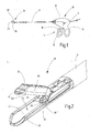
- FIG. 1 Figure 10 illustrates an instrument 10 which may serve to pinch, fuse, and disrupt biological tissue, such as a vessel, eg, a blood vessel, when operating on a human or animal body.
- the instrument 10 can be used in particular for endoscopic surgery. It has a slender shaft 11, which is held at its proximal end to a housing 12. This has a handling means such as a handle 13 and actuators 14. These may for example consist of a pivotable handle portion 15 and / or an actuating knob or lever 16 and optionally other elements, such as electrical switches exist.
- the actuators 14 are over in FIG. 1 Only schematically indicated by dashed lines force transmission means 17 is connected to a arranged at the distal end of the shaft 11 tool 18.
- the tool 18 comprises at least two branches 19, 20 and a knife 21.
- the branches 19, 20 serve to clamp tissue, for example a vessel, by moving them towards each other, clamping and coagulating the vessel between each other.
- the knife 21 serves to sever the coagulated vessel.
- To the force transmission means may include push or pull members for moving one or both branches 19, 20 and a drive element 22 for actuating the blade 21.
- a drive element 22 may be, for example, an existing thin metal sheet metal strip 22, as he FIG. 8 is apparent.
- the drive element 22 extends from the blade 21 through a portion of the shaft 11 to the push and pull members. These in turn extend to a not further illustrated transmission, which transmits an emanating from the handle portion 15 drive movement on the knife 21.
- the transmission may be designed such that in the Movement of the handle portion 15 to the handle 13 towards the first branches 19, 20 are closed, the knife 21 is still in the rest position, ie outside a trapped between the industries 19, 20 space 23 remains. This condition is in FIG. 2 illustrated.
- the gear can be further configured so that on the last piece of movement of the handle portion 15 toward the handle 13 in already closed branches 19, 20, the knife 21 is advanced toward the distal end of the tool 18 between the branches 19, 20.
- one of the branches 19, 20, for example the branch 20 may be provided with a slot 24 which extends longitudinally through the branch 20 to receive the knife 21.
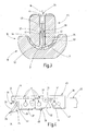
- the slot 24 is also off FIG. 3 seen.
- an actuator eg handle part 15
- other, in particular separate actuators for the tool 18 and the knife 21 may be provided.
- the guided in the slot 24 knife 21 consists for example of a metal plate, which, as from FIG. 4 can be seen, at its distal end a cutting nose 25 and an adjoining shaft 26 has.
- the cutting nose 25 and the shaft 26 are preferably a part of a metal plate of 0.1 mm to 0.2 mm, preferably 0.15 mm thickness, with two flat sides 27, 28, the FIG. 3 emerge.
- the cutting nose 25 forms a blade with a point 29, starting from which a front cutting edge 30 extends obliquely rising away. At an acute angle thereto and thus parallel to the first sector 19, the cutting nose 25 has a cutting edge 31 which slides in use on the first sector 19.
- the rectangular cross-section shaft 26 extends away from the cutting nose 25 and ends at a preferably stepped or also, as shown, obliquely arranged edge 32. This concludes with the preferably straight upper edge 33 of the shaft 26, preferably an obtuse angle ⁇ of, for example, 110 ° to 130 °, for example, 115 °, a.
- the drive element 22 has the edge 32 opposite to an end edge 34, which is preferably oriented parallel to the edge 32 and thereby defines a parallel gap 35 with this.
- the edge 34 preferably includes an acute angle ⁇ of, for example, 65 ° with the top 36 of the drive element 22.
- the approximately parallel to the top 33 of the shaft 26 extending lower edge 37 is preferably formed straight and may be provided with a step 38.
- the shaft 26 preferably has at least one opening 39. This can be round, square or otherwise formed. It serves for the positive locking of an insulator 40, which is preferably formed by a plastic part.
- the insulator 40 at least partially envelops the shank 26 of the knife 21, the insulator 40 preferably leaving the cutting nose 25 of the knife 21 free.
- the insulator 40 may be formed by a plastic injection-molded part, preferably consisting of a temperature-resistant thermosetting plastic. How out FIG. 3 combined with FIG.
- the insulator preferably has two flat portions 41, 42 which cover the flanks 27, 28 of the shaft 26 and which are interconnected by a portion extending through the opening 39. Above the top of the shaft 26 and below the lower edge 37, the sections 41, 42 may be interconnected, so that a total of a compact insulating body is formed. The joint lower degree the sections 41, 42 runs, as FIG. 4 shows, below the lower edge of the shaft 26, but above the cutting edge 31st
- the drive member 22 projects into the insulator 40 and is enveloped by this.
- the insulator 40 has at its distal end an insulator spine 44, which encloses a front end 45 of the knife 21 and projects beyond the cutting nose 25.
- a free space 46 is formed, which forms a re-entrant corner, preferably at a right angle.
- the cutting nose 25 is arranged.
- the insulator spur 44 is according to FIG. 3 thicker than the cutting nose 25, which thus can not touch the inner wall surfaces of the slot 24.
- an opening 47 which is penetrated by the material of the insulator 40, to connect the drive member 22 and the insulator 40 in a form-fitting manner.
- the material of the insulator 40 may also fill the parallel gap 35.
- the insulator 40 is how FIG. 3 shows, preferably flat on both sides.
- the sections 41, 42 have a thickness of 0.1 mm to 0.3 mm.
- the material thickness of the sections 41, 42 is, for example, 0.2 mm to 0.3 mm, preferably 0.26 mm.
- the material thickness of the corresponding sections of the insulator 40 is preferably 0.1 mm to 0.2 mm, for example 0.16 mm.
- the insulator 40 may also be provided with a step 48 at the bottom thereof at the step 38. This, together with a provided at the first sector 19 or the shaft 11 stage 49 a vertical actuating mechanism 50 (see Figure 5 to 7 ).
- the insulator 40 as FIG. 4 shows, be provided at several points with recesses 51 through which the shaft 26 or one end of the drive member 22 is accessible. These recesses 51 can serve for positioning of the blade 21 and the drive element 22 during the manufacture of the insulator 40 by prototyping.
- the drive element 22 extends through the entire shaft 11 and thereby serves to move the blade 21 in the longitudinal direction L.
- the drive element 22 is designed to tensile and compressive stiffness. In addition, it runs in the shaft 11 at corresponding mating surfaces, which, as in FIG. 8 illustrated by arrows, position-dependent forces F1 and F2 exert on the drive member 22. These forces are transmitted through the insulator 40 to the knife 21, so that its tip 29 and cutting edge 31 with bias on the first (lower) industry 19 slide.
- the isolator 40 interrupts each current path between the blade 21 and the second electrode surface 52 and the industry 20 and thus ensures that the knife 21, even if it enters the slot 24 somewhat prematurely, no significant part of serving for coagulation current takes over. This ultimately opens even the possibility of vessel transection, during the final phase of coagulation of the vessel ends clamped between the branches 19, 29. Thus, a shortening of the operation time can be achieved. However, it is essential that there is an increase in coagulation safety. Even if the knife 21 is actuated prematurely, this does not affect the quality of the coagulation result.
- the insulator 40 may also include the entire drive element 22.
- the blade 21 and the drive member 22 may be integrally formed or otherwise connected to each other.
- the drive element may also be wholly or partly formed of an electrically non-conductive material.
- the insulator 40 may be a component of the drive element 22.
- the distal end of the driver 22 may form the insulator 40.
- an instrument 10 for coagulation and fusion and for the separation of vessels two branches 19, 20 are provided, between which a vessel is to be grasped and fused.
- a knife 21 for severing the coagulated and fused vessel is provided with an insulator 40 which insulates the knife 21 against at least one of the electrodes or branches 19, 20.
- the knife 21 is preferably in mechanical contact with at least one of the electrodes or branches 19, 20, so that a secure separation of the fused biological tissue or vessel is achieved. This concept can be used to increase the safety of operation and to miniaturize the tool 18 towards smaller dimensions.
Landscapes
- Health & Medical Sciences (AREA)
- Surgery (AREA)
- Life Sciences & Earth Sciences (AREA)
- Engineering & Computer Science (AREA)
- Biomedical Technology (AREA)
- Public Health (AREA)
- Nuclear Medicine, Radiotherapy & Molecular Imaging (AREA)
- Veterinary Medicine (AREA)
- Otolaryngology (AREA)
- Heart & Thoracic Surgery (AREA)
- Medical Informatics (AREA)
- Molecular Biology (AREA)
- Animal Behavior & Ethology (AREA)
- General Health & Medical Sciences (AREA)
- Physics & Mathematics (AREA)
- Plasma & Fusion (AREA)
- Surgical Instruments (AREA)
- Knives (AREA)
Abstract
Description
- Die Erfindung betrifft ein Instrument zum Fassen, Koagulieren und Durchtrennen von Geweben, insbesondere zum Abklemmen, Verschließen und Durchtrennen von Gefäßen, insbesondere Blutgefäßen, am lebenden Körper eines menschlichen oder tierischen Patienten.
- Instrumente zum Verschließen und Trennen von Blutgefäßen sind beispielsweise der
DE 602 26 015 T2 zu entnehmen. - Typischerweise weisen solche Instrumente einen länglichen Schaft auf, der sich von einem Griff weg erstreckt. An dem distalen Ende des Schafts ist ein Werkzeug mit zwei Branchen zum Abklemmen eines Blutgefäßes angeordnet. Außerdem ist dort ein längs verschiebbares Messer angeordnet, um ein gefasstes und koaguliertes Gefäß durchtrennen zu können. Die Branchen und das Messer sind über entsprechende Betätigungsorgane an dem Handgriff zu betätigen. Die Branchen sind als Elektroden ausgebildet und gezielt bestrombar, um das zwischen ihnen geklemmte Gefäß zu erwärmen und die Gefäßwände durch Koagulation zu fusionieren.
- Vor der Durchtrennung von Blutgefäßen muss sichergestellt werden, dass die Koagulation in ausreichendem Maße stattgefunden hat, so dass die Enden des durchtrennten Gefäßes verlässlich geschlossen bleiben.
- Davon ausgehend ist es Aufgabe der Erfindung, ein Instrument zur Gefäßfusion und Trennung zu schaffen, mit dem sich Gefäße verlässlich verschließen und durchtrennen lassen.
- Diese Aufgabe wird mit dem Instrument nach Anspruch 1 gelöst:
- Das erfindungsgemäße Instrument weist ein Werkzeug mit zwei Branchen auf, von denen wenigstens eine beweglich ist, so dass sie aufeinander zu und voneinander weg bewegbar sind. Die beiden Branchen bilden ein Maul beziehungsweise ein Mittel zum Greifen von Gewebe, das sich über ein entsprechendes sich durch den Schaft erstreckendes Übertragungselement, beispielsweise einen Zugdraht, schließen lässt. Zu dem Werkzeug gehört weiter ein Messer, das in Ruheposition außerhalb eines zwischen den Branchen definierten Raumes steht und durch ein Antriebselement in diesem Raum eingeführt werden kann. Das Messer besteht vorzugsweise aus einem elektrisch leitfähigen Material, zum Beispiel Edelstahl. Das Antriebselement kann ebenfalls aus einem elektrisch leitfähigen Material, zum Beispiel Edelstahl, ausgebildet sein. Zur Betätigung der beweglichen Branche(n) und des Messers sind an dem Gehäuse ein oder mehrere Betätigungsorgane angebracht, die dazu dienen, zunächst das Maul zu schließen und dann das Messer in das Maul einzufahren. Zur Verbindung des Messers mit dem Antriebselement ist ein Isolator vorgesehen, der eine mechanische Verbindung zwischen dem Antriebselement und dem Messer erbringt, ohne einen Strompfad zwischen beiden zuzulassen. Damit wird die Ausbildung eines parasitären Strompfades unterbunden, der sonst entstehen könnte, wenn das Messer während des Koagulationsprozesses womöglich durch versehentliche Fehlbedienung schon etwas aus seiner Ruhelage heraus zwischen die Branchen bewegt wird.
- Die erfindungsgemäße Maßnahme führt auch dazu, dass das Instrument in unterschiedlichen Milieus, beispielsweise auch in Ansammlungen physiologischer Kochsalzlösung oder ähnlichen elektrisch leitfähigen Fluiden, genutzt werden kann. Die Isolation des Messers von dem Antriebselement verhindert bzw. reduziert die Möglichkeit parasitärer Strompfade innerhalb des Werkzeugs oder Schafts des Instruments und stellt somit sicher, dass der auf das biologische Gewebe zu applizierende Strom tatsächlich seinen Weg durch das biologische Gewebe nimmt. Damit wird die gewünschte Intensität des Koagulationsprozesses sichergestellt. Insbesondere wird aber ermöglicht, dass die Bestromung der Branchen vorgenommen und/oder fortgesetzt werden kann, wenn das Messer aus seiner Ruheposition in die Aktivposition bewegt wird. Es wird vermieden, dass über das Messer ein Kurzschluss zwischen den Branchen bzw. ihren Elektroden kommt. Es wird verhindert, dass elektrischer Strom über das Messer an dem Gewebe vorbeigeführt wird. Der elektrische Strom wird von einer Elektrode über das geklemmte Gewebe zu der jeweils anderen Elektrode geleitet. Damit wird die Koagulation des geklemmten Gewebes positiv beeinflusst und auch dann sichergestellt, wenn der Anwender das Messer vorzeitig betätigt. Dies ist insbesondere bei zweistufigen Werkzeugantrieben denkbar, bei denen ein Betätigungsgriff dazu genutzt wird, auf den ersten Teil seines Wegs die Branchen zu schließen und auf einen zweiten, letzten Wegstück das Messer vorzuschieben. Bewegt der Anwender den Handhebel gegebenenfalls unbewusst zu weit in Richtung der Betätigungsposition des Messers, kann dieses schon etwas bewegt werden und somit zumindest einen Teil des Koagulationsstroms übernehmen. Die erfindungsgemäße Isolation des Messers vermeidet diese Fehlermöglichkeit.
- Die erste Elektrode weist vorzugsweise eine Messergleitfläche auf, an der das Messer entlanglaufen kann. Auf diese Weise entsteht ein elektrischer Kontakt zwischen der ersten Elektrode und dem Messer, zumindest während des Durchtrennens des koagulierten Gefäßes. Es kann sich somit ein Stromfluss zwischen dem koagulierten Gewebe und dem Messer ergeben, der die Koagulation negativ beeinflussen kann.. Die Isolation des Messers vermeidet diesen Stromfluss sowie auch eine Schädigung des Messers oder seiner Schneidkante oder Spitze durch Stromfluss.
- Dem Messer kann ein Vertikalstellmechanismus zugeordnet sein, um das Messer in Abhängigkeit von seiner Längsbewegung quer vorzugsweise senkrecht zu dieser Bewegung zu verstellen, um die Spitze des Messers schwebend zu führen und nur mit der ersten Elektrode nicht aber mit sonstigen Kanten, Stufen oder dergleichen, in Berührung zu bringen. Dies schont das Messer und sorgt für seine anhaltende Schärfe auch bei wiederholter Benutzung.
- Die beiden Elektroden weisen vorzugsweise eine zueinander komplementäre Form auf, so dass sie im geschlossenen Zustand zwischen einander einen Spalt von im Wesentlichen konstanter Weite festlegen. Dieser Spalt kann eben oder gewölbt ausgebildet sein. Das Messer ist derart angeordnet und geführt, dass es diesen Spalt durchquert. Vorzugsweise läuft es dabei innerhalb einer der beiden Branchen, die dazu geschlitzt ausgebildet ist, während es auf der Elektrode der anderen Branche gleitet.
- Das Messer ist vorzugsweise als Lamelle, d.h. als dünne Metallplatte ausgebildet. Beispielsweise ist es aus einem 0,1 mm bis 0,2 mm starken härtbaren Klingenstahl gefertigt. Es kann eine Länge von einigen Millimetern, beispielsweise 7 mm bis 10 mm und eine Höhe von wenigen Millimetern, beispielsweise 2 mm bis 3 mm aufweisen. Vorzugsweise weist es an seinem distalen Ende eine Schneidnase mit mindestens einer Schneidkante sowie einen sich von der Schneidnase weg erstreckenden Schaft auf. Die Schneidnase und der Schaft können an ein und demselben Metallstück ausgebildet sein und somit nahtlos ineinander übergehen.
- Der Isolator ist vorzugsweise ein Kunststoffkörper, in den sich zumindest der Schaft des Messers hinein erstreckt. Dabei bedeckt der Isolator vorzugsweise zumindest die beiden flachen seitlichen Flanken des Schafts und verhindert somit, einen großflächigen Kontakt zwischen dem Messer und vorhandenem biologischem Gewebe sowie etwaiger vorhandener Flüssigkeit. Außerdem erstreckt sich der Isolator oberhalb des Schafts des Messers bis zu einem Isolatorsporn, der sich oberhalb der Schneidnase erstreckt. Der Isolator und sein Isolatorsporn sind (gemessen quer zur Bewegungsrichtung des Messers) dicker als das Messer, insbesondere dicker als seine Schneidnase. So wird jeder elektrische Kontakt zwischen dem Messer und der zweiten Branche vermieden, in deren Schlitz das Messer einfahrbar ist. Die Schneidnase ist geschützt in einer Aussparung des Isolators angeordnet.
- Es ist zweckmäßig, wenn der Schaft sowie das Antriebselement jeweils mindestens eine Öffnung aufweisen, die von dem Isolator durchsetzt ist. Auf diese Weise wird ein Formschluss zwischen dem Isolator und dem Antriebselement sowie dem Isolator und dem Messer erhalten. Weiter vorzugsweise legen das Messer und das Antriebselement einen Spalt fest, der als Parallelspalt ausgebildet sein kann. Dieser Spalt kann von Material des Isolators gefüllt sein. Vorzugsweise ist dieser Spalt schräg zur Bewegungsrichtung des Messers orientiert. Damit ergibt sich eine mechanisch belastbare Verbindung zwischen dem Antriebselement und dem Messer, über die insbesondere nicht nur Zug- und Druckbewegungen, sondern auch eine vertikal dazu gerichtete Andruckkraft von dem Antriebselement auf das Messer übertragbar sind. Diese Andruckkraft kann das Messer gegen die ungeschlitzte erste Elektrode drücken und somit ein sauberes Durchtrennen des koagulierten Gewebes unterstützen.
- Weitere Einzelheiten vorteilhafter Ausführungsformen der Erfindung sind Gegenstand der Zeichnung, der Beschreibung oder von Unteransprüchen. In der Beschreibung eines Ausführungsbeispiels verwendete richtungsbezogene Begriffe, wie oben, unten, obere, untere usw. beziehen sich auf Richtungen in der Zeichnung und sind insoweit nicht einschränkend auszulegen. Es zeigen:
-
Figur 1 ein erfindungsgemäßes Instrument in schematisierter Darstellung. -
Figur 2 das Werkzeug des erfindungsgemäßen Instruments, in perspektivischer Ansicht. -
Figur 3 das Werkzeug nachFigur 2 , in Querschnitt. -
Figur 4 Messer, Isolator und Antriebselement des Werkzeugs nachFigur 3 , in ausschnittsweiser Seitenansicht. -
Figur 5 bis 7 das Werkzeug mit geschlossenen Branchen in verschiedenen Betätigungsstellungen und -
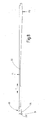
Figur 8 das Messer, das Antriebselement und den Isolator gemäßFigur 4 in Gesamtansicht. - In
Figur 1 ist ein Instrument 10 veranschaulicht, das zum Abklemmen, Fusionieren und Durchtrennen von biologischem Gewebe, beispielsweise eines Gefäßes, z.B. eines Blutgefäßes beim Operieren an einem menschlichen oder tierischen Körper dienen kann. Das Instrument 10 kann insbesondere zur endoskopischen Chirurgie eingesetzt werden. Es weist einen schlanken Schaft 11 auf, der an seinem proximalen Ende an einem Gehäuse 12 gehalten ist. Dieses weist ein Handhabungsmittel wie beispielsweise einen Handgriff 13 sowie Betätigungselemente 14 auf. Diese können zum Beispiel aus einem schwenkbaren Griffteil 15 und/oder einem Betätigungsknopf oder Hebel 16 sowie gegebenenfalls weiteren Elementen, z.B. elektrischen Schaltern, bestehen. Die Betätigungselemente 14 sind über inFigur 1 lediglich schematisch gestrichelt angedeutete Kraftübertragungsmittel 17 mit einem an dem distalen Ende des Schafts 11 angeordneten Werkzeug 18 verbunden. Das Werkzeug 18 umfasst mindestens zwei Branchen 19, 20 sowie ein Messer 21. Die Branchen 19, 20 dienen zum Abklemmen von Gewebe, beispielsweise eines Gefäßes, indem sie aufeinander zu bewegt werden, das Gefäß zwischen einander festklemmen und koagulieren. Das Messer 21 dient dazu, das koagulierte Gefäß zu durchtrennen. - Zu dem Kraftübertragungsmittel können Schub- oder Zugglieder zur Bewegung einer oder beider Branchen 19, 20 sowie ein Antriebselement 22 zur Betätigung des Messers 21 gehören. Ein solches Antriebselement 22 kann beispielsweise ein aus dünnem Blech bestehender Metallstreifen 22 sein, wie er aus
Figur 8 ersichtlich ist. Das Antriebselement 22 erstreckt sich von dem Messer 21 durch einen Teilbereich des Schafts 11 bis zu den Schub- und Zuggliedern. Diese erstrecken sich wiederum zu einem nicht weiter veranschaulichten Getriebe, das eine von dem Griffteil 15 ausgehende Antriebsbewegung auf das Messer 21 überträgt. Beispielsweise kann das Getriebe derart ausgebildet sein, dass bei der Bewegung des Griffteils 15 zu dem Handgriff 13 hin zunächst die Branchen 19, 20 geschlossen werden, wobei das Messer 21 noch in Ruhestellung, d.h. außerhalb eines zwischen den Branchen 19, 20 eingeschlossenen Raums 23 bleibt. Dieser Zustand ist inFigur 2 veranschaulicht. Das Getriebe kann weiter so ausgebildet sein, dass auf dem letzten Stück der Bewegung des Griffteils 15 zu dem Handgriff 13 hin bei bereits geschlossenen Branchen 19, 20 das Messer 21 zu dem distalen Ende des Werkzeugs 18 hin zwischen die Branchen 19, 20 vorgeschoben wird. Dazu kann eine der Branchen 19, 20, beispielsweise die Branche 20, mit einem Schlitz 24 versehen sein, der sich längs durch die Branche 20 erstreckt, um das Messer 21 aufzunehmen. Der Schlitz 24 ist darüber hinaus ausFigur 3 ersichtlich. Anstelle des oben beschriebenen Getriebes, das die Bewegung der Branchen 19, 20 und des Messers 21 aus einer Bewegung eines Betätigungsorgans (z.B. Griffteil 15) ableitet, können auch andere, insbesondere getrennte Betätigungsorgane für das Werkzeug 18 und das Messer 21 vorgesehen sein. - Das in dem Schlitz 24 geführte Messer 21 besteht beispielsweise aus einer Metalllamelle, die, wie aus
Figur 4 ersichtlich ist, an ihrem distalen Ende eine Schneidnase 25 und einen sich daran anschließenden Schaft 26 aufweist. Die Schneidnase 25 und der Schaft 26 sind vorzugsweise ein Teil eines Metallplättchens von 0,1 mm bis 0,2 mm, vorzugsweise 0,15 mm Dicke, mit zwei Flachseiten 27, 28, die ausFigur 3 hervorgehen. Die Schneidnase 25 bildet eine Klinge mit einer Spitze 29, von der ausgehend sich eine Frontschneidkante 30 schräg ansteigend weg erstreckt. Im spitzen Winkel dazu und damit parallel zur ersten Branche 19 weist die Schneidnase 25 eine Schneidkante 31 auf, die in Benutzung an der ersten Branche 19 gleitet. - Der im Querschnitt rechteckige Schaft 26 erstreckt sich von der Schneidnase 25 weg und endet an einer vorzugsweise gestuften oder auch, wie dargestellt, schräg angeordneten Kante 32. Diese schließt mit der vorzugsweise geraden oberen Kante 33 des Schafts 26, vorzugsweise einen stumpfen Winkel α von zum Beispiel 110° bis 130°, beispielsweise 115°, ein.
- Das Antriebselement 22 weist der Kante 32 gegenüber liegend eine stirnseitige Kante 34 auf, die vorzugsweise parallel zu der Kante 32 orientiert ist und dadurch mit dieser einen Parallelspalt 35 festlegt. Die Kante 34 schließt mit der Oberseite 36 des Antriebselements 22 vorzugsweise einen spitzen Winkel β von zum Beispiel 65° ein.
- Die sich etwa parallel zu der Oberseite 33 des Schafts 26 erstreckende untere Kante 37 ist vorzugsweise gerade ausgebildet und kann mit einer Stufe 38 versehen sein. Außerdem weist der Schaft 26 vorzugsweise mindestens eine Öffnung 39 auf. Diese kann rund, eckig oder anderweitig ausgebildet sein. Sie dient der formschlüssigen Sicherung eines Isolators 40, der vorzugsweise durch ein Kunststoffteil gebildet ist. Der Isolator 40 hüllt zumindest teilweise den Schaft 26 des Messers 21 ein, wobei der Isolator 40 vorzugsweise die Schneidnase 25 des Messers 21 frei lässt. Der Isolator 40 kann durch ein Kunststoff-Spritzgussteil gebildet sein, vorzugsweise bestehend aus einem temperaturbeständigen Duroplast. Wie aus
Figur 3 in Verbindung mitFigur 4 hervorgeht, weist der Isolator vorzugsweise zwei flache Abschnitte 41, 42 auf, die die Flanken 27, 28 des Schafts 26 bedecken und die durch einen sich durch die Öffnung 39 erstreckenden Abschnitt untereinander verbunden sind. Oberhalb der Oberseite des Schafts 26 sowie unterhalb der unteren Kante 37 können die Abschnitte 41, 42 untereinander verbunden sein, so dass insgesamt ein kompakter Isolationskörper ausgebildet ist. Der gemeinsame untere Abschluss der Abschnitte 41, 42 verläuft, wieFigur 4 zeigt, unterhalb der Unterkante des Schafts 26, jedoch oberhalb der Schneidkante 31. - Wie
Figur 4 zeigt, ragt das Antriebselement 22 in den Isolator 40 hinein und wird von diesem umhüllt. Vorzugsweise weist der Isolator 40 an seinem distalen Ende einen Isolatorsporn 44 auf, der ein vorderes Ende 45 des Messers 21 umhüllt und über die Schneidnase 25 ragt. Unterhalb des I-solatorsporns ist ein Freiraum 46 ausgebildet, der eine einspringende Ecke mit vorzugsweise einem rechten Winkel bildet. In dem Freiraum 46 ist die Schneidnase 25 angeordnet. Der Isolatorsporn 44 ist gemäßFigur 3 dicker als die Schneidnase 25, die somit die Innenwandflächen des Schlitzes 24 nicht berühren kann. - Es kann in dem Antriebselement 22 eine Öffnung 47 vorgesehen sein, die von Material des Isolators 40 durchsetzt ist, um das Antriebselement 22 und den Isolator 40 formschlüssig zu verbinden. Das Material des Isolators 40 kann außerdem den Parallelspalt 35 ausfüllen.
- Der Isolator 40 ist, wie
Figur 3 zeigt, an seinen beiden Seiten vorzugsweise flach ausgebildet. Die Abschnitte 41, 42 weisen eine Dicke von 0,1 mm bis 0,3 mm auf. Im Bereich des Schafts 26 beträgt die Materialstärke der Abschnitte 41, 42 z.B. 0,2 mm bis 0,3 mm, vorzugsweise 0,26 mm. Im Bereich des Antriebselements 22 beträgt die Materialstärke der entsprechenden Abschnitte des Isolators 40 vorzugsweise 0,1 mm bis 0,2 mm, z.B. 0,16 mm. Damit wird sowohl eine ausreichende mechanische Stabilität sowie eine gewünschte elektrische Isolation insbesondere der Schneidnase 25 durch ausreichende Beabstandung zu den Flanken des Schlitzes 24 erreicht. - Der Isolator 40 kann an seiner Unterseite bei der Stufe 38 ebenfalls mit einer Stufe 48 versehen sein. Diese bildet zusammen mit einer an der ersten Branche 19 oder dem Schaft 11 vorgesehenen Stufe 49 einen Vertikalstellmechanismus 50 (siehe
Figur 5 bis 7 ). Außerdem kann der Isolator 40, wieFigur 4 zeigt, an mehren Stellen mit Ausnehmungen 51 versehen sein, durch die der Schaft 26 oder auch ein Ende des Antriebselements 22 zugänglich ist. Diese Ausnehmungen 51 können zur Positionierung des Messers 21 und des Antriebselements 22 während der Herstellung des Isolators 40 durch Urformen dienen. - Von dem Isolator 40 ausgehend erstreckt sich das Antriebselement 22 durch den gesamten Schaft 11 und dient dabei zur Bewegung des Messers 21 in Längsrichtung L. Das Antriebeselement 22 ist dazu zug- und drucksteif ausgebildet. Außerdem läuft es in dem Schaft 11 an entsprechenden Gegenflächen, die, wie in
Figur 8 durch Pfeile veranschaulicht, positionsabhängig Kräfte F1 und F2 auf das Antriebselement 22 ausüben. Diese Kräfte werden durch den Isolator 40 auf das Messer 21 übertragen, so dass dessen Spitze 29 und Schneidkante 31 mit Vorspannung an der ersten (unteren) Branche 19 gleiten. - Das insoweit beschriebene Instrument 10 arbeitet wie folgt:
- Das Instrument 10 wird in der in
Figur 1 und 2 veranschaulichten Position so an ein Gefäß herangeführt, dass dieses zwischen den beiden Branchen 19, 20 liegt. Der Anwender zieht dann das Griffteil 15 an den Handgriff 13 heran, womit zunächst bei noch in Rückzugsposition befindlichem Messer 21 die Branchen 19, 20 geschlossen werden. Das Gefäß wird somit zwischen der Elektrodenfläche 52 der ersten Branche 19 und der Elektrodenfläche 53 der zweiten Branche 20 gefasst und so weit abgequetscht, dass sich die einander gegenüber liegenden Gefäßwände berühren. Über den Betätigungsknopf 16 kann der Bediener nun die Aktivierung der Elektrodenflächen 52, 53 veranlassen, wobei ein zur Koagulation des Gefäßes dienender Strom zu den Branchen 19, 20 geleitet wird. Es kann sich dabei zum Beispiel um eine hochfrequente Wechselspannung handeln. Eine an dem distalen Ende einer der Branchen, zum Beispiel der Branche 20, vorgesehene Nase oder ein sonstiger Vorsprung 54 stellt dabei sicher, dass zwischen den Branchen 19, 20 ein definierter Spalt 55 eingehalten wird. Der Stromfluss zwischen den Elektrodenflächen 52, 53 läuft vollständig über das dazwischen gefasste biologische Material und koaguliert dieses. Das Messer 21 befindet sich dabei, wieFigur 5 zeigt, in Rückzugsposition. - Will der Anwender nun das koagulierte Gefäß durchtrennen, bewegt er das Griffteil 15 gegebenenfalls unter Überwindung eines erhöhten Widerstands weiter gegen den Handgriff 13, woraufhin das Messer 21, wie aus
Figur 6 ersichtlich, in den Schlitz 24 der Branche 20 eingeschoben wird. Der Vertikalstellmechanismus 50 hält die Spitze 29 und die Kante 31 dabei noch schwebend über der Elektrodenfläche 52 der Branche 19. Im weiteren Verlauf der Vorwärtsbewegung senken sich die Schneidkante 31 und die Spitze 29 jedoch auf die Elektrodenfläche 52 ab, wie es dieFiguren 6 und 7 veranschaulichen. Das Messer 21 wird nun von dem Antriebselement 22 bis zu dem Vorsprung 54 hin vorgeschoben und durchtrennt das koagulierte Gefäß. Dabei unterbricht der Isolator 40 jeden Strompfad zwischen dem Messer 21 und der zweiten Elektrodenfläche 52 sowie der Branche 20 und stellt somit sicher, dass das Messer 21 auch dann, wenn es etwas vorzeitig in den Schlitz 24 gelangt, keinen nennenswerten Teil des zur Koagulation dienenden Stroms übernimmt. Dies eröffnet letztendlich sogar die Möglichkeit der Gefäßdurchtrennung, während der Endphase der Koagulation der zwischen den Branchen 19, 29 festgeklemmten Gefäßenden. Damit kann eine Verkürzung der Operationszeit erreicht werden. Wesentlich aber ist, dass eine Erhöhung der Koagulationssicherheit zu verzeichnen ist. Auch wenn das Messer 21 vorzeitig betätigt wird, beeinflusst dies die Qualität des Koagulationsergebnisses nicht. - Es sei darauf hingewiesen, dass der Isolator 40 auch das gesamte Antriebselement 22 einschließen kann. In diesem Fall können das Messer 21 und das Antriebselement 22 einstückig ausgebildet oder anderweitig miteinander verbunden sein.
- Außerdem wird darauf hingewiesen, dass das Antriebselement auch ganz oder teilweise aus einem elektrisch nichtleitenden Material ausgebildet sein kann. In diesem Fall kann der Isolator 40 ein Bestandteil des Antriebselements 22 sein. Z.B. kann das distale Ende des Antriebselements 22 den Isolator 40 bilden.
- Bei einem Instrument 10 zur Koagulation und Fusion sowie zur Durchtrennung von Gefäßen sind zwei Branchen 19, 20 vorgesehen, zwischen denen ein Gefäß zu fassen und zu fusionieren ist. Ein Messer 21 zur Durchtrennung des koagulierten und fusionierten Gefäßes ist mit einem Isolator 40 versehen, der das Messer 21 gegen mindestens eine der Elektroden bzw. Branchen 19, 20 isoliert. Andererseits ist das Messer 21 vorzugsweise mit mindestens einer der Elektroden bzw. Branchen 19, 20 in mechanischem Kontakt, so dass eine sichere Trennung des fusionierten biologischen Gewebes bzw. Gefäßes erreicht wird. Dieses Konzept kann zur Erhöhung der Operationssicherheit und zur Miniaturisierung des Werkzeugs 18 hin zu kleineren Abmessungen genutzt werden.
-
10 Instrument 11 Schaft 12 Gehäuse 13 Handgriff 14 Betätigungselemente 15 Griffteil 16 Betätigungsknopf- oder -hebel 17 Kraftübertragungsmittel 18 Werkzeug 19 erste Branche 20 zweite (obere) Branche 21 Messer 22 Antriebselement für 21 23 Raum zwischen den Branchen 19 und 20 24 Schlitz in 20 25 Schneidnase von 21 26 Schaft 27, 28 Flachseiten von 26 α, β Winkel 29 Spitze von 25 30 Frontschneidkante von 25 31 Schneidkante an Unterseite von 25 32 rückseitige Kante von 26 33 Oberseite von 26 34 stirnseitige Kante von 22 35 Parallelspalt 36 Oberseite von 22 37 untere Kante von 26 38 Stufe der unteren Kante von 26 39 Öffnung in 26 40 Isolator 41, 42 Abschnitte 44 Isolatorsporn 45 distales Ende des Messers 21 46 Freiraum 47 Öffnung in 22 48 Stufe an 40 49 Stufe an 19 50 Vertikalstellmechanismus 51 Positionierungs-Ausnehmungen in 40 52 Elektrodenfläche von 19 53 Elektrodenfläche von 20 54 Vorsprung 55 Spalt zwischen den Branchen 19 und 20 L Längsrichtung
Claims (15)
- Instrument (10) zur Gefäßfusion und Trennung,
mit einem länglichen Schaft (11), der sich von einem Gehäuse (12) weg erstreckt und an seinem distalen Ende ein Werkzeug (18) trägt,
mit einer ersten Branche (19), die zu dem Werkzeug gehört und eine erste Elektrodenfläche (52) aufweist,
mit einer zweiten Brache (20), die zu dem Werkzeug gehört und auf die erste Elektrodenfläche (52) zu und von dieser weg beweglich gelagert ist, wobei die zweite Branche (20) eine Elektrodenfläche (53) und einen Längsschlitz (24) aufweist,
mit einem Messer (21), das zu dem Werkzeug (18) gehört und aus einem elektrisch leitfähigen Material besteht sowie relativ zu dem Schaft (11) beweglich angeordnet und in den Längsschlitz (24) hineinragend oder in diesen einfahrbar angeordnet ist,
mit einem Antriebselement (22), das sich von dem Gehäuse (12) durch den Schaft (11) zu dem Messer (21) erstreckt und
mit einem Isolator (40), der das Messer (21) und das Antriebselement (22) miteinander verbindend angeordnet ist. - Instrument nach Anspruch 1, dadurch gekennzeichnet, dass die erste Elektrodenfläche (52) eine Messergleitfläche ist.
- Instrument nach einem der vorstehenden Ansprüche, dadurch gekennzeichnet, dass dem Messer (21) ein Vertikalstellmechanismus (50) zugeordnet ist, um das Messer (21) in Abhängigkeit von seiner Längsbewegung quer zu der Längsbewegung zu verstellen, wobei der Vertikalstellmechanismus (50) dazu eingerichtet ist, das Messer (21) bei einer entlang der ersten Branche (19) gerichteten Vorschubbewegung senkrecht zu der Vorschubbewegung auf die erste Elektrodenfläche (52) hin und bei einer entlang der ersten Branche (19) gerichteten Rückzugsbewegung senkrecht zu der Rückzugsbewegung von der ersten Elektrodenfläche (52) weg zu bewegen.
- Instrument nach einem der vorstehenden Ansprüche, dadurch gekennzeichnet, dass die zweite Branche (20) durch einen massiven Metallkörper gebildet ist und an ihrer der Elektrodenfläche (52) der ersten Branche (19) zugewandten Seite eine der Form der Elektrodenfläche (52) folgende Form aufweist.
- Instrument nach einem der vorstehenden Ansprüche, dadurch gekennzeichnet, dass mindestens eine der Branchen (19, 20) einen Vorsprung (54) aufweist, um bei geschlossenen Branchen (19, 20) des Instruments (10) zwischen der Elektrodenfläche (52) und der Elektrodenfläche (53) der zweiten Branche (20) einen Spalt (55) festzulegen.
- Instrument nach einem der vorstehenden Ansprüche, dadurch gekennzeichnet, dass das Antriebselement (22) elektrisch leitend ausgebildet ist.
- Instrument nach einem der vorstehenden Ansprüche, dadurch gekennzeichnet, dass das Messer (21) als Lamelle mit zwei flachen seitlichen Flanken (27, 28) ausgebildet ist.
- Instrument nach einem der vorstehenden Ansprüche, dadurch gekennzeichnet, dass das Messer (21) eine Schneidnase (25) und einen Schaft (26) aufweist,
- Instrument nach Anspruch 8, dadurch gekennzeichnet, dass die Schneidnase (25) eine der ersten Elektrodenfläche (52) zugewandte und parallel zu dieser angeordnete geschärfte Schneidkante (31) sowie eine stirnseitige geschärfte Schneidkante (30) aufweist, die in einem Winkel zu der Bewegungsrichtung des Messers (21) orientiert ist.
- Instrument nach einem Anspruch 7, dadurch gekennzeichnet, dass sich der Schaft (26) des Messers (21) in den Isolator (40) erstreckt.
- Instrument nach einem der vorstehenden Ansprüche, dadurch gekennzeichnet, dass der Isolator (40) einen Isolatorsporn (44) aufweist, der oberhalb einer Schneidnase (25) des Messers (21) angeordnet ist.
- Instrument nach Anspruch 10, dadurch gekennzeichnet, dass der Schaft (26) wenigstens eine Öffnung (39) aufweist, die von dem Isolator (40) durchsetzt ist, und dass das Antriebselement (22) mindestens eine Öffnung (47) aufweist, die von dem Isolator (40) durchsetzt ist.
- Instrument nach eine der vorstehenden Ansprüche, dadurch gekennzeichnet, dass sich das Antriebselement (22) in den Isolator (40) erstreckt.
- Instrument nach einem der vorstehenden Ansprüche, dadurch gekennzeichnet, dass das Messer (21) und das Antriebselement (22) zwischen einander einen Spalt (35) festlegen.
- Instrument nach einem der vorstehenden Ansprüche, dadurch gekennzeichnet, dass der Spalt (35) zu der Bewegungsrichtung des Messers (21) schräg orientiert ist.
Priority Applications (8)
| Application Number | Priority Date | Filing Date | Title |
|---|---|---|---|
| PL13159361T PL2777583T3 (pl) | 2013-03-15 | 2013-03-15 | Instrument do fuzji naczyń i przecinania |
| EP13159361.8A EP2777583B1 (de) | 2013-03-15 | 2013-03-15 | Instrument zur Gefäßfusion und Trennung |
| US14/208,792 US10617464B2 (en) | 2013-03-15 | 2014-03-13 | Instrument for vessel fusion and separation |
| KR1020140029675A KR101619583B1 (ko) | 2013-03-15 | 2014-03-13 | 혈관 융합 및 분리용 기기 |
| BR102014005880-0A BR102014005880B1 (pt) | 2013-03-15 | 2014-03-13 | Instrumento para fusão e separação de vaso |
| CN201410094316.1A CN104042330B (zh) | 2013-03-15 | 2014-03-14 | 用于脉管融合和分离的器具 |
| JP2014051504A JP5739557B2 (ja) | 2013-03-15 | 2014-03-14 | 脈管の融合及び分離のための器具 |
| RU2014109850A RU2693447C2 (ru) | 2013-03-15 | 2014-03-14 | Инструмент для сращивания и рассечения сосудов |
Applications Claiming Priority (1)
| Application Number | Priority Date | Filing Date | Title |
|---|---|---|---|
| EP13159361.8A EP2777583B1 (de) | 2013-03-15 | 2013-03-15 | Instrument zur Gefäßfusion und Trennung |
Publications (2)
| Publication Number | Publication Date |
|---|---|
| EP2777583A1 true EP2777583A1 (de) | 2014-09-17 |
| EP2777583B1 EP2777583B1 (de) | 2020-07-01 |
Family
ID=47915457
Family Applications (1)
| Application Number | Title | Priority Date | Filing Date |
|---|---|---|---|
| EP13159361.8A Not-in-force EP2777583B1 (de) | 2013-03-15 | 2013-03-15 | Instrument zur Gefäßfusion und Trennung |
Country Status (8)
| Country | Link |
|---|---|
| US (1) | US10617464B2 (de) |
| EP (1) | EP2777583B1 (de) |
| JP (1) | JP5739557B2 (de) |
| KR (1) | KR101619583B1 (de) |
| CN (1) | CN104042330B (de) |
| BR (1) | BR102014005880B1 (de) |
| PL (1) | PL2777583T3 (de) |
| RU (1) | RU2693447C2 (de) |
Families Citing this family (78)
| Publication number | Priority date | Publication date | Assignee | Title |
|---|---|---|---|---|
| US11229472B2 (en) | 2001-06-12 | 2022-01-25 | Cilag Gmbh International | Modular battery powered handheld surgical instrument with multiple magnetic position sensors |
| US9089360B2 (en) | 2008-08-06 | 2015-07-28 | Ethicon Endo-Surgery, Inc. | Devices and techniques for cutting and coagulating tissue |
| US8663220B2 (en) | 2009-07-15 | 2014-03-04 | Ethicon Endo-Surgery, Inc. | Ultrasonic surgical instruments |
| US11090104B2 (en) | 2009-10-09 | 2021-08-17 | Cilag Gmbh International | Surgical generator for ultrasonic and electrosurgical devices |
| US10441345B2 (en) | 2009-10-09 | 2019-10-15 | Ethicon Llc | Surgical generator for ultrasonic and electrosurgical devices |
| US8469981B2 (en) | 2010-02-11 | 2013-06-25 | Ethicon Endo-Surgery, Inc. | Rotatable cutting implement arrangements for ultrasonic surgical instruments |
| JP6165780B2 (ja) | 2012-02-10 | 2017-07-19 | エシコン・エンド−サージェリィ・インコーポレイテッドEthicon Endo−Surgery,Inc. | ロボット制御式の手術器具 |
| US9439668B2 (en) | 2012-04-09 | 2016-09-13 | Ethicon Endo-Surgery, Llc | Switch arrangements for ultrasonic surgical instruments |
| US20140005705A1 (en) | 2012-06-29 | 2014-01-02 | Ethicon Endo-Surgery, Inc. | Surgical instruments with articulating shafts |
| US20140005702A1 (en) | 2012-06-29 | 2014-01-02 | Ethicon Endo-Surgery, Inc. | Ultrasonic surgical instruments with distally positioned transducers |
| US9226767B2 (en) | 2012-06-29 | 2016-01-05 | Ethicon Endo-Surgery, Inc. | Closed feedback control for electrosurgical device |
| US9393037B2 (en) | 2012-06-29 | 2016-07-19 | Ethicon Endo-Surgery, Llc | Surgical instruments with articulating shafts |
| US9351754B2 (en) | 2012-06-29 | 2016-05-31 | Ethicon Endo-Surgery, Llc | Ultrasonic surgical instruments with distally positioned jaw assemblies |
| US9408622B2 (en) | 2012-06-29 | 2016-08-09 | Ethicon Endo-Surgery, Llc | Surgical instruments with articulating shafts |
| US9326788B2 (en) | 2012-06-29 | 2016-05-03 | Ethicon Endo-Surgery, Llc | Lockout mechanism for use with robotic electrosurgical device |
| US9198714B2 (en) | 2012-06-29 | 2015-12-01 | Ethicon Endo-Surgery, Inc. | Haptic feedback devices for surgical robot |
| US9095367B2 (en) | 2012-10-22 | 2015-08-04 | Ethicon Endo-Surgery, Inc. | Flexible harmonic waveguides/blades for surgical instruments |
| US20140135804A1 (en) | 2012-11-15 | 2014-05-15 | Ethicon Endo-Surgery, Inc. | Ultrasonic and electrosurgical devices |
| US9814514B2 (en) | 2013-09-13 | 2017-11-14 | Ethicon Llc | Electrosurgical (RF) medical instruments for cutting and coagulating tissue |
| US9265926B2 (en) | 2013-11-08 | 2016-02-23 | Ethicon Endo-Surgery, Llc | Electrosurgical devices |
| GB2521228A (en) | 2013-12-16 | 2015-06-17 | Ethicon Endo Surgery Inc | Medical device |
| US9795436B2 (en) | 2014-01-07 | 2017-10-24 | Ethicon Llc | Harvesting energy from a surgical generator |
| US9554854B2 (en) | 2014-03-18 | 2017-01-31 | Ethicon Endo-Surgery, Llc | Detecting short circuits in electrosurgical medical devices |
| US10092310B2 (en) | 2014-03-27 | 2018-10-09 | Ethicon Llc | Electrosurgical devices |
| US9737355B2 (en) | 2014-03-31 | 2017-08-22 | Ethicon Llc | Controlling impedance rise in electrosurgical medical devices |
| US9913680B2 (en) | 2014-04-15 | 2018-03-13 | Ethicon Llc | Software algorithms for electrosurgical instruments |
| US10285724B2 (en) | 2014-07-31 | 2019-05-14 | Ethicon Llc | Actuation mechanisms and load adjustment assemblies for surgical instruments |
| US10639092B2 (en) | 2014-12-08 | 2020-05-05 | Ethicon Llc | Electrode configurations for surgical instruments |
| US10245095B2 (en) | 2015-02-06 | 2019-04-02 | Ethicon Llc | Electrosurgical instrument with rotation and articulation mechanisms |
| US10595929B2 (en) | 2015-03-24 | 2020-03-24 | Ethicon Llc | Surgical instruments with firing system overload protection mechanisms |
| US11051873B2 (en) | 2015-06-30 | 2021-07-06 | Cilag Gmbh International | Surgical system with user adaptable techniques employing multiple energy modalities based on tissue parameters |
| US10765470B2 (en) | 2015-06-30 | 2020-09-08 | Ethicon Llc | Surgical system with user adaptable techniques employing simultaneous energy modalities based on tissue parameters |
| US10898256B2 (en) | 2015-06-30 | 2021-01-26 | Ethicon Llc | Surgical system with user adaptable techniques based on tissue impedance |
| US10034704B2 (en) | 2015-06-30 | 2018-07-31 | Ethicon Llc | Surgical instrument with user adaptable algorithms |
| US11129669B2 (en) | 2015-06-30 | 2021-09-28 | Cilag Gmbh International | Surgical system with user adaptable techniques based on tissue type |
| US10687884B2 (en) | 2015-09-30 | 2020-06-23 | Ethicon Llc | Circuits for supplying isolated direct current (DC) voltage to surgical instruments |
| US10595930B2 (en) | 2015-10-16 | 2020-03-24 | Ethicon Llc | Electrode wiping surgical device |
| US10575892B2 (en) | 2015-12-31 | 2020-03-03 | Ethicon Llc | Adapter for electrical surgical instruments |
| US11129670B2 (en) | 2016-01-15 | 2021-09-28 | Cilag Gmbh International | Modular battery powered handheld surgical instrument with selective application of energy based on button displacement, intensity, or local tissue characterization |
| US11058448B2 (en) | 2016-01-15 | 2021-07-13 | Cilag Gmbh International | Modular battery powered handheld surgical instrument with multistage generator circuits |
| US10716615B2 (en) | 2016-01-15 | 2020-07-21 | Ethicon Llc | Modular battery powered handheld surgical instrument with curved end effectors having asymmetric engagement between jaw and blade |
| US12193698B2 (en) | 2016-01-15 | 2025-01-14 | Cilag Gmbh International | Method for self-diagnosing operation of a control switch in a surgical instrument system |
| US11229471B2 (en) | 2016-01-15 | 2022-01-25 | Cilag Gmbh International | Modular battery powered handheld surgical instrument with selective application of energy based on tissue characterization |
| US10555769B2 (en) | 2016-02-22 | 2020-02-11 | Ethicon Llc | Flexible circuits for electrosurgical instrument |
| US10485607B2 (en) | 2016-04-29 | 2019-11-26 | Ethicon Llc | Jaw structure with distal closure for electrosurgical instruments |
| US10646269B2 (en) * | 2016-04-29 | 2020-05-12 | Ethicon Llc | Non-linear jaw gap for electrosurgical instruments |
| US10456193B2 (en) | 2016-05-03 | 2019-10-29 | Ethicon Llc | Medical device with a bilateral jaw configuration for nerve stimulation |
| US10376305B2 (en) | 2016-08-05 | 2019-08-13 | Ethicon Llc | Methods and systems for advanced harmonic energy |
| US11266430B2 (en) | 2016-11-29 | 2022-03-08 | Cilag Gmbh International | End effector control and calibration |
| EP3406218A1 (de) | 2017-05-24 | 2018-11-28 | Erbe Elektromedizin GmbH | Koagulations- und dissektions-instrument mit stiftelektroden |
| KR102020179B1 (ko) * | 2019-04-09 | 2019-11-05 | 최보환 | 전기수술 핸드피이스용 전도성 전극 |
| US11812957B2 (en) | 2019-12-30 | 2023-11-14 | Cilag Gmbh International | Surgical instrument comprising a signal interference resolution system |
| US12053224B2 (en) | 2019-12-30 | 2024-08-06 | Cilag Gmbh International | Variation in electrode parameters and deflectable electrode to modify energy density and tissue interaction |
| US12082808B2 (en) | 2019-12-30 | 2024-09-10 | Cilag Gmbh International | Surgical instrument comprising a control system responsive to software configurations |
| US12349961B2 (en) | 2019-12-30 | 2025-07-08 | Cilag Gmbh International | Electrosurgical instrument with electrodes operable in bipolar and monopolar modes |
| US11723716B2 (en) | 2019-12-30 | 2023-08-15 | Cilag Gmbh International | Electrosurgical instrument with variable control mechanisms |
| US11937863B2 (en) | 2019-12-30 | 2024-03-26 | Cilag Gmbh International | Deflectable electrode with variable compression bias along the length of the deflectable electrode |
| US12262937B2 (en) | 2019-12-30 | 2025-04-01 | Cilag Gmbh International | User interface for surgical instrument with combination energy modality end-effector |
| US11779387B2 (en) | 2019-12-30 | 2023-10-10 | Cilag Gmbh International | Clamp arm jaw to minimize tissue sticking and improve tissue control |
| US12336747B2 (en) | 2019-12-30 | 2025-06-24 | Cilag Gmbh International | Method of operating a combination ultrasonic / bipolar RF surgical device with a combination energy modality end-effector |
| US11950797B2 (en) | 2019-12-30 | 2024-04-09 | Cilag Gmbh International | Deflectable electrode with higher distal bias relative to proximal bias |
| US20210196361A1 (en) | 2019-12-30 | 2021-07-01 | Ethicon Llc | Electrosurgical instrument with monopolar and bipolar energy capabilities |
| US11707318B2 (en) | 2019-12-30 | 2023-07-25 | Cilag Gmbh International | Surgical instrument with jaw alignment features |
| US11779329B2 (en) | 2019-12-30 | 2023-10-10 | Cilag Gmbh International | Surgical instrument comprising a flex circuit including a sensor system |
| US11944366B2 (en) | 2019-12-30 | 2024-04-02 | Cilag Gmbh International | Asymmetric segmented ultrasonic support pad for cooperative engagement with a movable RF electrode |
| US12114912B2 (en) | 2019-12-30 | 2024-10-15 | Cilag Gmbh International | Non-biased deflectable electrode to minimize contact between ultrasonic blade and electrode |
| US11911063B2 (en) | 2019-12-30 | 2024-02-27 | Cilag Gmbh International | Techniques for detecting ultrasonic blade to electrode contact and reducing power to ultrasonic blade |
| US12343063B2 (en) | 2019-12-30 | 2025-07-01 | Cilag Gmbh International | Multi-layer clamp arm pad for enhanced versatility and performance of a surgical device |
| US11452525B2 (en) | 2019-12-30 | 2022-09-27 | Cilag Gmbh International | Surgical instrument comprising an adjustment system |
| US11986234B2 (en) | 2019-12-30 | 2024-05-21 | Cilag Gmbh International | Surgical system communication pathways |
| US12023086B2 (en) | 2019-12-30 | 2024-07-02 | Cilag Gmbh International | Electrosurgical instrument for delivering blended energy modalities to tissue |
| US11660089B2 (en) | 2019-12-30 | 2023-05-30 | Cilag Gmbh International | Surgical instrument comprising a sensing system |
| US11696776B2 (en) | 2019-12-30 | 2023-07-11 | Cilag Gmbh International | Articulatable surgical instrument |
| US11786291B2 (en) | 2019-12-30 | 2023-10-17 | Cilag Gmbh International | Deflectable support of RF energy electrode with respect to opposing ultrasonic blade |
| US12064109B2 (en) | 2019-12-30 | 2024-08-20 | Cilag Gmbh International | Surgical instrument comprising a feedback control circuit |
| US11986201B2 (en) | 2019-12-30 | 2024-05-21 | Cilag Gmbh International | Method for operating a surgical instrument |
| US12076006B2 (en) | 2019-12-30 | 2024-09-03 | Cilag Gmbh International | Surgical instrument comprising an orientation detection system |
| CN113729874A (zh) * | 2021-10-08 | 2021-12-03 | 浙江百安医疗科技有限公司 | 一种脐带切割器 |
Citations (5)
| Publication number | Priority date | Publication date | Assignee | Title |
|---|---|---|---|---|
| WO1995015124A1 (en) * | 1993-12-02 | 1995-06-08 | Cabot Technology Corporation | Cutting and coagulating forceps |
| EP1810625A1 (de) * | 2006-01-24 | 2007-07-25 | Sherwood Services AG | Gefäßversiegelungs- und trennungsvorrichtung für große Gewebe-Strukturen |
| WO2008124271A1 (en) * | 2007-04-03 | 2008-10-16 | Aragon Surgical, Inc. | Method and apparatus for sealing tissue |
| US20110087221A1 (en) * | 2009-10-09 | 2011-04-14 | Tyco Healthcare Group Lp | Vessel Sealer and Divider With Captured Cutting Element |
| EP2554133A1 (de) * | 2011-08-02 | 2013-02-06 | Erbe Elektromedizin GmbH | Instrument zur Gefäßfusion und -trennung mit zwei Branchen und einer gekrümmten Elektrode |
Family Cites Families (19)
| Publication number | Priority date | Publication date | Assignee | Title |
|---|---|---|---|---|
| SU980704A1 (ru) | 1981-03-26 | 1982-12-15 | Запорожский государственный медицинский институт | Веноэкстрактор |
| US5462546A (en) * | 1993-02-05 | 1995-10-31 | Everest Medical Corporation | Bipolar electrosurgical forceps |
| CA2138076A1 (en) * | 1993-12-17 | 1995-06-18 | Philip E. Eggers | Monopolar electrosurgical instruments |
| US20030171747A1 (en) | 1999-01-25 | 2003-09-11 | Olympus Optical Co., Ltd. | Medical treatment instrument |
| EP2263586B1 (de) | 2001-04-06 | 2018-06-06 | Covidien AG | Blutgefässdichtungs- und -trennungsgerät |
| US6773434B2 (en) * | 2001-09-18 | 2004-08-10 | Ethicon, Inc. | Combination bipolar forceps and scissors instrument |
| JP4461008B2 (ja) * | 2002-05-10 | 2010-05-12 | タイコ ヘルスケア グループ エルピー | 電気手術用ステープリング装置 |
| US7150749B2 (en) * | 2003-06-13 | 2006-12-19 | Sherwood Services Ag | Vessel sealer and divider having elongated knife stroke and safety cutting mechanism |
| EP3162309B1 (de) | 2004-10-08 | 2022-10-26 | Ethicon LLC | Chirurgisches ultraschallinstrument |
| US8298232B2 (en) | 2006-01-24 | 2012-10-30 | Tyco Healthcare Group Lp | Endoscopic vessel sealer and divider for large tissue structures |
| RU2318465C1 (ru) | 2006-04-21 | 2008-03-10 | Валерий Иванович Чиссов | Способ микроволновой диатермокоагуляции биоткани и устройство для его осуществления |
| US8475453B2 (en) * | 2006-10-06 | 2013-07-02 | Covidien Lp | Endoscopic vessel sealer and divider having a flexible articulating shaft |
| CA2664167A1 (en) | 2006-10-06 | 2008-04-17 | Tyco Healthcare Group Lp | Endoscopic vessel sealer and divider having a flexible articulating shaft |
| US7950561B2 (en) | 2007-06-18 | 2011-05-31 | Tyco Healthcare Group Lp | Structure for attachment of buttress material to anvils and cartridges of surgical staplers |
| US8852183B2 (en) * | 2009-06-05 | 2014-10-07 | Microline Surgical Inc. | Scissor tip for bipolar high frequency endoscope |
| US8668690B2 (en) * | 2010-06-03 | 2014-03-11 | Covidien Lp | Apparatus and method for optimal tissue separation |
| US9113865B2 (en) | 2010-09-30 | 2015-08-25 | Ethicon Endo-Surgery, Inc. | Staple cartridge comprising a layer |
| JP5814685B2 (ja) | 2011-08-05 | 2015-11-17 | オリンパス株式会社 | 治療用処置装置 |
| US20140194874A1 (en) * | 2013-01-10 | 2014-07-10 | Ethicon Endo-Surgery, Inc. | Electrosurgical end effector with independent closure feature and blade |
-
2013
- 2013-03-15 EP EP13159361.8A patent/EP2777583B1/de not_active Not-in-force
- 2013-03-15 PL PL13159361T patent/PL2777583T3/pl unknown
-
2014
- 2014-03-13 BR BR102014005880-0A patent/BR102014005880B1/pt not_active IP Right Cessation
- 2014-03-13 US US14/208,792 patent/US10617464B2/en not_active Expired - Fee Related
- 2014-03-13 KR KR1020140029675A patent/KR101619583B1/ko not_active Expired - Fee Related
- 2014-03-14 RU RU2014109850A patent/RU2693447C2/ru active
- 2014-03-14 JP JP2014051504A patent/JP5739557B2/ja not_active Expired - Fee Related
- 2014-03-14 CN CN201410094316.1A patent/CN104042330B/zh not_active Expired - Fee Related
Patent Citations (5)
| Publication number | Priority date | Publication date | Assignee | Title |
|---|---|---|---|---|
| WO1995015124A1 (en) * | 1993-12-02 | 1995-06-08 | Cabot Technology Corporation | Cutting and coagulating forceps |
| EP1810625A1 (de) * | 2006-01-24 | 2007-07-25 | Sherwood Services AG | Gefäßversiegelungs- und trennungsvorrichtung für große Gewebe-Strukturen |
| WO2008124271A1 (en) * | 2007-04-03 | 2008-10-16 | Aragon Surgical, Inc. | Method and apparatus for sealing tissue |
| US20110087221A1 (en) * | 2009-10-09 | 2011-04-14 | Tyco Healthcare Group Lp | Vessel Sealer and Divider With Captured Cutting Element |
| EP2554133A1 (de) * | 2011-08-02 | 2013-02-06 | Erbe Elektromedizin GmbH | Instrument zur Gefäßfusion und -trennung mit zwei Branchen und einer gekrümmten Elektrode |
Also Published As
| Publication number | Publication date |
|---|---|
| BR102014005880A2 (pt) | 2016-02-23 |
| JP2014180573A (ja) | 2014-09-29 |
| BR102014005880B1 (pt) | 2022-02-15 |
| KR101619583B1 (ko) | 2016-05-10 |
| US10617464B2 (en) | 2020-04-14 |
| CN104042330B (zh) | 2017-01-11 |
| RU2014109850A (ru) | 2015-09-20 |
| CN104042330A (zh) | 2014-09-17 |
| US20140276806A1 (en) | 2014-09-18 |
| KR20140113459A (ko) | 2014-09-24 |
| EP2777583B1 (de) | 2020-07-01 |
| RU2693447C2 (ru) | 2019-07-02 |
| JP5739557B2 (ja) | 2015-06-24 |
| PL2777583T3 (pl) | 2020-11-16 |
Similar Documents
| Publication | Publication Date | Title |
|---|---|---|
| EP2777583B1 (de) | Instrument zur Gefäßfusion und Trennung | |
| EP3578125B1 (de) | Laparoskopisches zangeninstrument | |
| EP2522291B1 (de) | Elektrochirurgisches Instrument | |
| DE102016100588B4 (de) | Elektrochirurgisches Instrument mit elektrisch leitfähigen Anschlagelementen und Verfahren zur Herstellung eines Backenelements für ein elektrochirurgisches Instrument | |
| EP2077785B1 (de) | Rohrschaftinstrument | |
| DE69232781T2 (de) | Elektrochirurgisches schneidwerkzeug | |
| EP2959854B1 (de) | Chirurgisches Instrument | |
| DE102017100296B4 (de) | Elektrochirurgische Vorrichtung | |
| EP1151723B1 (de) | Chirurgisches Instrument, insbesondere Pinzette oder Zange | |
| EP1336384B1 (de) | Medizinisches bipolares Instrument zum Schneiden von Gewebe | |
| EP1778114B1 (de) | Elektrochirurgisches instrument | |
| DE60121229T2 (de) | Vorrichtung zum abdichten und teilen eines gefässes mit nichtleitendem endanschlag | |
| EP2679186B1 (de) | Instrument zur Gefäßfusion und -trennung | |
| WO2001022896A1 (de) | Medizinisches bipolares instrument zum schneiden von gewebe | |
| DE102009037614A1 (de) | Elektrochirurgisches Instrument | |
| DE102004031141A1 (de) | Elektrochirurgisches Instrument | |
| DE102011079494A1 (de) | Elektrochirurgisches Greifinstrument | |
| EP3351198B1 (de) | Instrument zur gefässversiegelung | |
| EP2845550B1 (de) | Chirurgisches Instrument mit Kunststoffschaft | |
| EP2554133B1 (de) | Instrument zur Gefäßfusion und -trennung mit zwei Branchen und mit einer gekrümmten Elektrode | |
| EP2653123B1 (de) | Werkzeug für ein medizinisches Instrument | |
| DE19915062C1 (de) | Chirurgisches Instrument | |
| EP4371515B1 (de) | Koagulationsinstrument | |
| DE202006016837U1 (de) | Endoskopische bipolare Zange mit Distanzstück | |
| DE29821617U1 (de) | Chirurgische Bipolarschere |
Legal Events
| Date | Code | Title | Description |
|---|---|---|---|
| PUAI | Public reference made under article 153(3) epc to a published international application that has entered the european phase |
Free format text: ORIGINAL CODE: 0009012 |
|
| 17P | Request for examination filed |
Effective date: 20130315 |
|
| AK | Designated contracting states |
Kind code of ref document: A1 Designated state(s): AL AT BE BG CH CY CZ DE DK EE ES FI FR GB GR HR HU IE IS IT LI LT LU LV MC MK MT NL NO PL PT RO RS SE SI SK SM TR |
|
| AX | Request for extension of the european patent |
Extension state: BA ME |
|
| RAP1 | Party data changed (applicant data changed or rights of an application transferred) |
Owner name: ERBE ELEKTROMEDIZIN GMBH |
|
| RIN1 | Information on inventor provided before grant (corrected) |
Inventor name: DUEPPUIS, MARTINA |
|
| GRAP | Despatch of communication of intention to grant a patent |
Free format text: ORIGINAL CODE: EPIDOSNIGR1 |
|
| STAA | Information on the status of an ep patent application or granted ep patent |
Free format text: STATUS: GRANT OF PATENT IS INTENDED |
|
| INTG | Intention to grant announced |
Effective date: 20191217 |
|
| GRAS | Grant fee paid |
Free format text: ORIGINAL CODE: EPIDOSNIGR3 |
|
| GRAJ | Information related to disapproval of communication of intention to grant by the applicant or resumption of examination proceedings by the epo deleted |
Free format text: ORIGINAL CODE: EPIDOSDIGR1 |
|
| GRAL | Information related to payment of fee for publishing/printing deleted |
Free format text: ORIGINAL CODE: EPIDOSDIGR3 |
|
| STAA | Information on the status of an ep patent application or granted ep patent |
Free format text: STATUS: REQUEST FOR EXAMINATION WAS MADE |
|
| INTC | Intention to grant announced (deleted) | ||
| GRAJ | Information related to disapproval of communication of intention to grant by the applicant or resumption of examination proceedings by the epo deleted |
Free format text: ORIGINAL CODE: EPIDOSDIGR1 |
|
| GRAP | Despatch of communication of intention to grant a patent |
Free format text: ORIGINAL CODE: EPIDOSNIGR1 |
|
| GRAJ | Information related to disapproval of communication of intention to grant by the applicant or resumption of examination proceedings by the epo deleted |
Free format text: ORIGINAL CODE: EPIDOSDIGR1 |
|
| GRAP | Despatch of communication of intention to grant a patent |
Free format text: ORIGINAL CODE: EPIDOSNIGR1 |
|
| GRAR | Information related to intention to grant a patent recorded |
Free format text: ORIGINAL CODE: EPIDOSNIGR71 |
|
| STAA | Information on the status of an ep patent application or granted ep patent |
Free format text: STATUS: GRANT OF PATENT IS INTENDED |
|
| GRAA | (expected) grant |
Free format text: ORIGINAL CODE: 0009210 |
|
| STAA | Information on the status of an ep patent application or granted ep patent |
Free format text: STATUS: THE PATENT HAS BEEN GRANTED |
|
| INTG | Intention to grant announced |
Effective date: 20200520 |
|
| AK | Designated contracting states |
Kind code of ref document: B1 Designated state(s): AL AT BE BG CH CY CZ DE DK EE ES FI FR GB GR HR HU IE IS IT LI LT LU LV MC MK MT NL NO PL PT RO RS SE SI SK SM TR |
|
| REG | Reference to a national code |
Ref country code: GB Ref legal event code: FG4D Free format text: NOT ENGLISH |
|
| REG | Reference to a national code |
Ref country code: CH Ref legal event code: EP Ref country code: AT Ref legal event code: REF Ref document number: 1285405 Country of ref document: AT Kind code of ref document: T Effective date: 20200715 |
|
| REG | Reference to a national code |
Ref country code: IE Ref legal event code: FG4D Free format text: LANGUAGE OF EP DOCUMENT: GERMAN |
|
| REG | Reference to a national code |
Ref country code: DE Ref legal event code: R096 Ref document number: 502013014858 Country of ref document: DE |
|
| REG | Reference to a national code |
Ref country code: LT Ref legal event code: MG4D |
|
| PG25 | Lapsed in a contracting state [announced via postgrant information from national office to epo] |
Ref country code: BG Free format text: LAPSE BECAUSE OF FAILURE TO SUBMIT A TRANSLATION OF THE DESCRIPTION OR TO PAY THE FEE WITHIN THE PRESCRIBED TIME-LIMIT Effective date: 20201001 |
|
| REG | Reference to a national code |
Ref country code: NL Ref legal event code: MP Effective date: 20200701 |
|
| PG25 | Lapsed in a contracting state [announced via postgrant information from national office to epo] |
Ref country code: CZ Free format text: LAPSE BECAUSE OF FAILURE TO SUBMIT A TRANSLATION OF THE DESCRIPTION OR TO PAY THE FEE WITHIN THE PRESCRIBED TIME-LIMIT Effective date: 20200701 Ref country code: ES Free format text: LAPSE BECAUSE OF FAILURE TO SUBMIT A TRANSLATION OF THE DESCRIPTION OR TO PAY THE FEE WITHIN THE PRESCRIBED TIME-LIMIT Effective date: 20200701 Ref country code: LT Free format text: LAPSE BECAUSE OF FAILURE TO SUBMIT A TRANSLATION OF THE DESCRIPTION OR TO PAY THE FEE WITHIN THE PRESCRIBED TIME-LIMIT Effective date: 20200701 Ref country code: HR Free format text: LAPSE BECAUSE OF FAILURE TO SUBMIT A TRANSLATION OF THE DESCRIPTION OR TO PAY THE FEE WITHIN THE PRESCRIBED TIME-LIMIT Effective date: 20200701 Ref country code: PT Free format text: LAPSE BECAUSE OF FAILURE TO SUBMIT A TRANSLATION OF THE DESCRIPTION OR TO PAY THE FEE WITHIN THE PRESCRIBED TIME-LIMIT Effective date: 20201102 Ref country code: SE Free format text: LAPSE BECAUSE OF FAILURE TO SUBMIT A TRANSLATION OF THE DESCRIPTION OR TO PAY THE FEE WITHIN THE PRESCRIBED TIME-LIMIT Effective date: 20200701 Ref country code: FI Free format text: LAPSE BECAUSE OF FAILURE TO SUBMIT A TRANSLATION OF THE DESCRIPTION OR TO PAY THE FEE WITHIN THE PRESCRIBED TIME-LIMIT Effective date: 20200701 Ref country code: NO Free format text: LAPSE BECAUSE OF FAILURE TO SUBMIT A TRANSLATION OF THE DESCRIPTION OR TO PAY THE FEE WITHIN THE PRESCRIBED TIME-LIMIT Effective date: 20201001 Ref country code: GR Free format text: LAPSE BECAUSE OF FAILURE TO SUBMIT A TRANSLATION OF THE DESCRIPTION OR TO PAY THE FEE WITHIN THE PRESCRIBED TIME-LIMIT Effective date: 20201002 |
|
| PG25 | Lapsed in a contracting state [announced via postgrant information from national office to epo] |
Ref country code: RS Free format text: LAPSE BECAUSE OF FAILURE TO SUBMIT A TRANSLATION OF THE DESCRIPTION OR TO PAY THE FEE WITHIN THE PRESCRIBED TIME-LIMIT Effective date: 20200701 Ref country code: LV Free format text: LAPSE BECAUSE OF FAILURE TO SUBMIT A TRANSLATION OF THE DESCRIPTION OR TO PAY THE FEE WITHIN THE PRESCRIBED TIME-LIMIT Effective date: 20200701 Ref country code: IS Free format text: LAPSE BECAUSE OF FAILURE TO SUBMIT A TRANSLATION OF THE DESCRIPTION OR TO PAY THE FEE WITHIN THE PRESCRIBED TIME-LIMIT Effective date: 20201101 |
|
| PG25 | Lapsed in a contracting state [announced via postgrant information from national office to epo] |
Ref country code: NL Free format text: LAPSE BECAUSE OF FAILURE TO SUBMIT A TRANSLATION OF THE DESCRIPTION OR TO PAY THE FEE WITHIN THE PRESCRIBED TIME-LIMIT Effective date: 20200701 |
|
| REG | Reference to a national code |
Ref country code: DE Ref legal event code: R097 Ref document number: 502013014858 Country of ref document: DE |
|
| PG25 | Lapsed in a contracting state [announced via postgrant information from national office to epo] |
Ref country code: EE Free format text: LAPSE BECAUSE OF FAILURE TO SUBMIT A TRANSLATION OF THE DESCRIPTION OR TO PAY THE FEE WITHIN THE PRESCRIBED TIME-LIMIT Effective date: 20200701 Ref country code: DK Free format text: LAPSE BECAUSE OF FAILURE TO SUBMIT A TRANSLATION OF THE DESCRIPTION OR TO PAY THE FEE WITHIN THE PRESCRIBED TIME-LIMIT Effective date: 20200701 Ref country code: SM Free format text: LAPSE BECAUSE OF FAILURE TO SUBMIT A TRANSLATION OF THE DESCRIPTION OR TO PAY THE FEE WITHIN THE PRESCRIBED TIME-LIMIT Effective date: 20200701 Ref country code: RO Free format text: LAPSE BECAUSE OF FAILURE TO SUBMIT A TRANSLATION OF THE DESCRIPTION OR TO PAY THE FEE WITHIN THE PRESCRIBED TIME-LIMIT Effective date: 20200701 |
|
| PLBE | No opposition filed within time limit |
Free format text: ORIGINAL CODE: 0009261 |
|
| STAA | Information on the status of an ep patent application or granted ep patent |
Free format text: STATUS: NO OPPOSITION FILED WITHIN TIME LIMIT |
|
| PG25 | Lapsed in a contracting state [announced via postgrant information from national office to epo] |
Ref country code: AL Free format text: LAPSE BECAUSE OF FAILURE TO SUBMIT A TRANSLATION OF THE DESCRIPTION OR TO PAY THE FEE WITHIN THE PRESCRIBED TIME-LIMIT Effective date: 20200701 |
|
| 26N | No opposition filed |
Effective date: 20210406 |
|
| PG25 | Lapsed in a contracting state [announced via postgrant information from national office to epo] |
Ref country code: SK Free format text: LAPSE BECAUSE OF FAILURE TO SUBMIT A TRANSLATION OF THE DESCRIPTION OR TO PAY THE FEE WITHIN THE PRESCRIBED TIME-LIMIT Effective date: 20200701 |
|
| PG25 | Lapsed in a contracting state [announced via postgrant information from national office to epo] |
Ref country code: SI Free format text: LAPSE BECAUSE OF FAILURE TO SUBMIT A TRANSLATION OF THE DESCRIPTION OR TO PAY THE FEE WITHIN THE PRESCRIBED TIME-LIMIT Effective date: 20200701 |
|
| PG25 | Lapsed in a contracting state [announced via postgrant information from national office to epo] |
Ref country code: MC Free format text: LAPSE BECAUSE OF FAILURE TO SUBMIT A TRANSLATION OF THE DESCRIPTION OR TO PAY THE FEE WITHIN THE PRESCRIBED TIME-LIMIT Effective date: 20200701 |
|
| REG | Reference to a national code |
Ref country code: CH Ref legal event code: PL |
|
| REG | Reference to a national code |
Ref country code: BE Ref legal event code: MM Effective date: 20210331 |
|
| PG25 | Lapsed in a contracting state [announced via postgrant information from national office to epo] |
Ref country code: LU Free format text: LAPSE BECAUSE OF NON-PAYMENT OF DUE FEES Effective date: 20210315 Ref country code: LI Free format text: LAPSE BECAUSE OF NON-PAYMENT OF DUE FEES Effective date: 20210331 Ref country code: CH Free format text: LAPSE BECAUSE OF NON-PAYMENT OF DUE FEES Effective date: 20210331 Ref country code: IE Free format text: LAPSE BECAUSE OF NON-PAYMENT OF DUE FEES Effective date: 20210315 |
|
| PGFP | Annual fee paid to national office [announced via postgrant information from national office to epo] |
Ref country code: GB Payment date: 20220322 Year of fee payment: 10 |
|
| REG | Reference to a national code |
Ref country code: AT Ref legal event code: MM01 Ref document number: 1285405 Country of ref document: AT Kind code of ref document: T Effective date: 20210315 |
|
| PGFP | Annual fee paid to national office [announced via postgrant information from national office to epo] |
Ref country code: IT Payment date: 20220323 Year of fee payment: 10 Ref country code: FR Payment date: 20220325 Year of fee payment: 10 |
|
| PG25 | Lapsed in a contracting state [announced via postgrant information from national office to epo] |
Ref country code: BE Free format text: LAPSE BECAUSE OF NON-PAYMENT OF DUE FEES Effective date: 20210331 |
|
| PGFP | Annual fee paid to national office [announced via postgrant information from national office to epo] |
Ref country code: DE Payment date: 20220428 Year of fee payment: 10 |
|
| PG25 | Lapsed in a contracting state [announced via postgrant information from national office to epo] |
Ref country code: AT Free format text: LAPSE BECAUSE OF NON-PAYMENT OF DUE FEES Effective date: 20210315 |
|
| PGFP | Annual fee paid to national office [announced via postgrant information from national office to epo] |
Ref country code: PL Payment date: 20220221 Year of fee payment: 10 |
|
| PG25 | Lapsed in a contracting state [announced via postgrant information from national office to epo] |
Ref country code: HU Free format text: LAPSE BECAUSE OF FAILURE TO SUBMIT A TRANSLATION OF THE DESCRIPTION OR TO PAY THE FEE WITHIN THE PRESCRIBED TIME-LIMIT; INVALID AB INITIO Effective date: 20130315 |
|
| PG25 | Lapsed in a contracting state [announced via postgrant information from national office to epo] |
Ref country code: CY Free format text: LAPSE BECAUSE OF FAILURE TO SUBMIT A TRANSLATION OF THE DESCRIPTION OR TO PAY THE FEE WITHIN THE PRESCRIBED TIME-LIMIT Effective date: 20200701 |
|
| REG | Reference to a national code |
Ref country code: DE Ref legal event code: R119 Ref document number: 502013014858 Country of ref document: DE |
|
| GBPC | Gb: european patent ceased through non-payment of renewal fee |
Effective date: 20230315 |
|
| PG25 | Lapsed in a contracting state [announced via postgrant information from national office to epo] |
Ref country code: GB Free format text: LAPSE BECAUSE OF NON-PAYMENT OF DUE FEES Effective date: 20230315 |
|
| PG25 | Lapsed in a contracting state [announced via postgrant information from national office to epo] |
Ref country code: GB Free format text: LAPSE BECAUSE OF NON-PAYMENT OF DUE FEES Effective date: 20230315 Ref country code: FR Free format text: LAPSE BECAUSE OF NON-PAYMENT OF DUE FEES Effective date: 20230331 Ref country code: DE Free format text: LAPSE BECAUSE OF NON-PAYMENT OF DUE FEES Effective date: 20231003 |
|
| PG25 | Lapsed in a contracting state [announced via postgrant information from national office to epo] |
Ref country code: MK Free format text: LAPSE BECAUSE OF FAILURE TO SUBMIT A TRANSLATION OF THE DESCRIPTION OR TO PAY THE FEE WITHIN THE PRESCRIBED TIME-LIMIT Effective date: 20200701 Ref country code: IT Free format text: LAPSE BECAUSE OF NON-PAYMENT OF DUE FEES Effective date: 20230315 |
|
| PG25 | Lapsed in a contracting state [announced via postgrant information from national office to epo] |
Ref country code: TR Free format text: LAPSE BECAUSE OF FAILURE TO SUBMIT A TRANSLATION OF THE DESCRIPTION OR TO PAY THE FEE WITHIN THE PRESCRIBED TIME-LIMIT Effective date: 20200701 |
|
| PG25 | Lapsed in a contracting state [announced via postgrant information from national office to epo] |
Ref country code: PL Free format text: LAPSE BECAUSE OF NON-PAYMENT OF DUE FEES Effective date: 20230315 |
|
| PG25 | Lapsed in a contracting state [announced via postgrant information from national office to epo] |
Ref country code: PL Free format text: LAPSE BECAUSE OF NON-PAYMENT OF DUE FEES Effective date: 20230315 |
|
| PG25 | Lapsed in a contracting state [announced via postgrant information from national office to epo] |
Ref country code: MT Free format text: LAPSE BECAUSE OF FAILURE TO SUBMIT A TRANSLATION OF THE DESCRIPTION OR TO PAY THE FEE WITHIN THE PRESCRIBED TIME-LIMIT Effective date: 20200701 |