EP2777471A2 - Dishwasher, in particular household dishwasher - Google Patents
Dishwasher, in particular household dishwasher Download PDFInfo
- Publication number
- EP2777471A2 EP2777471A2 EP14401019.6A EP14401019A EP2777471A2 EP 2777471 A2 EP2777471 A2 EP 2777471A2 EP 14401019 A EP14401019 A EP 14401019A EP 2777471 A2 EP2777471 A2 EP 2777471A2
- Authority
- EP
- European Patent Office
- Prior art keywords
- air
- heat pump
- pump device
- blower
- dishwasher
- Prior art date
- Legal status (The legal status is an assumption and is not a legal conclusion. Google has not performed a legal analysis and makes no representation as to the accuracy of the status listed.)
- Granted
Links
Images


Classifications
-
- A—HUMAN NECESSITIES
- A47—FURNITURE; DOMESTIC ARTICLES OR APPLIANCES; COFFEE MILLS; SPICE MILLS; SUCTION CLEANERS IN GENERAL
- A47L—DOMESTIC WASHING OR CLEANING; SUCTION CLEANERS IN GENERAL
- A47L15/00—Washing or rinsing machines for crockery or tableware
- A47L15/0018—Controlling processes, i.e. processes to control the operation of the machine characterised by the purpose or target of the control
- A47L15/0021—Regulation of operational steps within the washing processes, e.g. optimisation or improvement of operational steps depending from the detergent nature or from the condition of the crockery
- A47L15/0042—Desorption phases of reversibly dehydrogenated drying material, e.g. zeolite in a sorption drying system
-
- A—HUMAN NECESSITIES
- A47—FURNITURE; DOMESTIC ARTICLES OR APPLIANCES; COFFEE MILLS; SPICE MILLS; SUCTION CLEANERS IN GENERAL
- A47L—DOMESTIC WASHING OR CLEANING; SUCTION CLEANERS IN GENERAL
- A47L15/00—Washing or rinsing machines for crockery or tableware
- A47L15/42—Details
- A47L15/4291—Recovery arrangements, e.g. for the recovery of energy or water
-
- A—HUMAN NECESSITIES
- A47—FURNITURE; DOMESTIC ARTICLES OR APPLIANCES; COFFEE MILLS; SPICE MILLS; SUCTION CLEANERS IN GENERAL
- A47L—DOMESTIC WASHING OR CLEANING; SUCTION CLEANERS IN GENERAL
- A47L15/00—Washing or rinsing machines for crockery or tableware
- A47L15/42—Details
- A47L15/48—Drying arrangements
- A47L15/483—Drying arrangements by using condensers
-
- A—HUMAN NECESSITIES
- A47—FURNITURE; DOMESTIC ARTICLES OR APPLIANCES; COFFEE MILLS; SPICE MILLS; SUCTION CLEANERS IN GENERAL
- A47L—DOMESTIC WASHING OR CLEANING; SUCTION CLEANERS IN GENERAL
- A47L15/00—Washing or rinsing machines for crockery or tableware
- A47L15/42—Details
- A47L15/48—Drying arrangements
- A47L15/486—Blower arrangements
-
- A—HUMAN NECESSITIES
- A47—FURNITURE; DOMESTIC ARTICLES OR APPLIANCES; COFFEE MILLS; SPICE MILLS; SUCTION CLEANERS IN GENERAL
- A47L—DOMESTIC WASHING OR CLEANING; SUCTION CLEANERS IN GENERAL
- A47L15/00—Washing or rinsing machines for crockery or tableware
- A47L15/42—Details
- A47L15/48—Drying arrangements
- A47L15/488—Connections of the tub with the ambient air, e.g. air intake or venting arrangements
-
- Y—GENERAL TAGGING OF NEW TECHNOLOGICAL DEVELOPMENTS; GENERAL TAGGING OF CROSS-SECTIONAL TECHNOLOGIES SPANNING OVER SEVERAL SECTIONS OF THE IPC; TECHNICAL SUBJECTS COVERED BY FORMER USPC CROSS-REFERENCE ART COLLECTIONS [XRACs] AND DIGESTS
- Y02—TECHNOLOGIES OR APPLICATIONS FOR MITIGATION OR ADAPTATION AGAINST CLIMATE CHANGE
- Y02B—CLIMATE CHANGE MITIGATION TECHNOLOGIES RELATED TO BUILDINGS, e.g. HOUSING, HOUSE APPLIANCES OR RELATED END-USER APPLICATIONS
- Y02B30/00—Energy efficient heating, ventilation or air conditioning [HVAC]
- Y02B30/52—Heat recovery pumps, i.e. heat pump based systems or units able to transfer the thermal energy from one area of the premises or part of the facilities to a different one, improving the overall efficiency
-
- Y—GENERAL TAGGING OF NEW TECHNOLOGICAL DEVELOPMENTS; GENERAL TAGGING OF CROSS-SECTIONAL TECHNOLOGIES SPANNING OVER SEVERAL SECTIONS OF THE IPC; TECHNICAL SUBJECTS COVERED BY FORMER USPC CROSS-REFERENCE ART COLLECTIONS [XRACs] AND DIGESTS
- Y02—TECHNOLOGIES OR APPLICATIONS FOR MITIGATION OR ADAPTATION AGAINST CLIMATE CHANGE
- Y02B—CLIMATE CHANGE MITIGATION TECHNOLOGIES RELATED TO BUILDINGS, e.g. HOUSING, HOUSE APPLIANCES OR RELATED END-USER APPLICATIONS
- Y02B40/00—Technologies aiming at improving the efficiency of home appliances, e.g. induction cooking or efficient technologies for refrigerators, freezers or dish washers
Definitions
- the invention relates to a dishwasher, in particular in the embodiment as a domestic dishwasher, with a washing compartment providing a washing compartment, a condensation dryer for acting on a Spül necessarilyerwand with outside air and a heat pump device for heating of rinsing liquor.
- Dishwashers of the aforementioned type are well known in the art. They have a washing container, which in turn provides a washing room. When used as intended, the washing container serves to receive items to be cleaned.
- the washing compartment provided by the washing compartment is accessible to the user via a feed opening. This can be closed fluid-tight by means of a pivotable dishwasher door.
- a dishwasher For loading the items to be cleaned with rinse liquor, a dishwasher has a scavenging chamber side formed spray. This usually has two or three rotatable spray arms, by means of which in the normal operation of a circulating pump funded rinsing water is sprayed onto the items to be cleaned.
- a heat pump device for heating rinse liquor which extracts heat from the ambient air surrounding the automatic dishwasher for heating the rinsing liquor.
- automatic dishwashers For drying items to be washed after completion of a proper cleaning, automatic dishwashers known from the prior art typically have a condensation dryer. In one possible embodiment, this serves to subject a rinsing container wall to external air, which leads to a cooling of the rinsing container wall, with the result that moist air located in the interior of the rinsing container rests against the outside of the rinsing container wall can condense. The air in the rinsing container is thus deprived of moisture, which leads to the drying of the end of an intended continuous rinse program still hot items.
- the invention proposes a dishwasher of the type mentioned, which is characterized in that the condensation dryer and the heat pump device have a common blower.
- the condensation dryer known from the prior art has a blower. This serves to draw in the case of drying from outside room air and this outside on the washing container to lead past a Spül notionerwand. In the manner already described above, the rinsing container wall is cooled down, with the result that warm moist air located inside the rinsing container can condense on the inside of the cooled rinsing container wall.
- the dishwasher also has a heat pump device, which also has a fan. This serves to suck in air from the outside and to pass them through for heat transfer through an evaporator. With the heat pump device, a heating of the rinsing liquor is achieved, whereby it extracts heat from the outside air surrounding the automatic dishwasher for heating up the rinsing liquor.
- the condensation dryer and the heat pump device have a common blower, that the dishwashing machine therefore has only one blower, which is suitable and intended for this purpose, instead of a first blower for the condensation dryer and a second blower for the heat pump device, to be used both as a drying fan for the condensation dryer and as a heat pump fan for the heat pump device.
- a first blower for the condensation dryer and a second blower for the heat pump device instead of two blowers has the Dishwasher according to the invention only over a single blower.
- the embodiment according to the invention is advantageous in that it completely dispenses with a second fan. This provides a cost savings both in the production due to the achieved component reduction as well as during assembly. Moreover, it is advantageous that by eliminating a blower additional space is available within the dishwasher, for example, for the heat pump device, which allows an optimized design of the same.
- the fan provided according to the invention is downstream of an evaporator of the heat pump device according to one embodiment.
- the outside air sucked in by the blower thus first passes through the evaporator, which is upstream of the blower, on the machine side.
- the heat pump device is switched on, the outside air in the evaporator cools down.
- the heat pump device is switched off, the sucked outside air flows through the evaporator without any temperature change.
- the blower is preferably followed by an air switching device.
- the sucked air can be supplied to a first and / or a second flow path.
- the air is discharged from the dishwasher;
- the dishwasher has air discharge openings, preferably air discharge openings formed laterally and / or on the rear wall of the automatic dishwasher.
- This flow path is typically available when the heat pump device is in operation, that is to say during heating of rinsing liquor by means of the heat pump device.
- the cooled as a result of heating the rinsing liquor in the evaporator outside air is removed via the first flow path and directed out of the dishwasher.
- the second flow path is used in a condensation drying after completion of an intended continuous cleaning program use.
- the outside air sucked in via the blower will not be drained out of the dishwasher through the air outlets. Rather, there is an automatic internal deflection of the outside air, as a result, this flows outside of a Spül interchangeerwand the Spül practicers for the purpose of cooling the same.
- both flow paths are at least partially opened at the same time, ie the air conveyed by the fan is diverted both via the first flow path via the air discharge openings, in particular laterally and / or on the rear wall of the automatic dishwashing machine, as well as via the second flow path is passed to a Spül intuitionerwand outside on the outside.
- the ratio of the amounts of air distributed over the two flow paths is preferably adjustable and can be freely selected, for example, depending on the desired cooling effect of the washing compartment wall.
- the air switching device preferably has an air flap, with which a flow path, in particular the second flow path, can optionally be opened or closed, the air flap can in particular be designed to be pivotable. It can also be two louvers, namely for the first and the second flow path in each case such a damper be present. Alternatively, only one air flap may be present, which is assigned to both flow paths, and which releases the second flow path when the first flow path is closed, and vice versa.
- the use of only one blower according to the invention also has the advantage on the process side that, with the heat pump device otherwise switched off, the blower may be allowed to run for drying of the evaporator, which may be humid by condensation, of the heat pump device. In this case, such drying of the evaporator preferably takes place when the blower is already in operation for the purpose of condensation drying.
- the use of only one fan offers a synergistic effect in that on the one hand by the air promotion drying of the evaporator and on the other hand by cooling a Spül employmenterwand a condensation drying of the dishes is achieved. This synergistic effect does not arise in previously known from the prior art automatic dishwashers.
- the invention therefore further proposes a process for operating a dishwashing machine equipped with a heat pump device in which rinsing liquor is heated in a condenser in a heating phase and the outside air cooled in an evaporator is diverted by means of a blower and in which one Drying phase, the fan is operated with otherwise switched off heat pump device on.
- the heat pump device After carrying out the method according to the invention, a proper operation of the heat pump device takes place in a manner known per se, according to which there is a cooling of room air sucked in from outside. This cooled room air is discharged by means of the blower. As soon as the rinsing liquor is heated in the intended manner by means of the heat pump device, the heat pump device is switched off. According to the invention, it is now provided that the fan of the heat pump device is operated while the heat pump device is otherwise switched off. Advantageously, it is achieved that is still performed by the evaporator from outside sucked outside air. This leads advantageously to the fact that in the evaporator possibly accumulated condensate taken from the outside air passed through, that is, a drying of the evaporator is achieved. It is thus ensured that it does not come due to residual moisture to a contamination of the evaporator with an associated odor nuisance. Rather, the process implementation according to the invention ensures that the evaporator dries off after use as intended.
- the first drying phase is followed by a further drying phase, wherein in the further drying phase a rinsing container wall is charged with the outside air conveyed by the blower.
- this further drying phase condensation drying of the items to be washed picked up by the washing container thus takes place in a manner known per se.
- the blower is followed by an air switching device in the flow direction of the outside air, by means of which the outside air conveyed by the blower is optionally distributed to different flow paths according to a further feature of the invention.
- the distribution of the outside air conveyed by the fan to a first and / or a second flow path provides the already vorerläuterten advantages.
- the fan can be operated at a first speed and with respect to the first speed lower, in particular substantially lower speed, in particular the fan is speed controlled.
- the blower is operated during operation Heat pump device, ie in a Spülflottenaufloomphase, operated at the first speed, wherein a volume flow of at least 50m 3 / h is promoted.
- Heat pump device ie in a Spülflottenaufloomphase
- the fan is operated at a reduced speed, whereby an energetically particularly efficient operation of the automatic dishwasher is ensured.
- Fig. 1 can be seen in a schematic perspective view of a dishwasher 1 in the embodiment as a household dishwasher.
- the automatic dishwasher 1 has an outer housing 2. This accommodates a washing container 25 which provides a washing compartment 6.
- the rinsing container 25 is accessible from the front by means of a loading opening which can be closed in a fluid-tight manner by means of a pivotably arranged door 3.
- the door 3 retreats with respect to the plane of the drawing Fig. 1 4.
- a base region 5 On the underside of the door 3, a base region 5 is provided, which provides an air inlet 9 for outside, that is, room air 8.
- a cover plate 12 for example, arranged in the embodiment of a worktop, in particular the representation of Fig. 2 lets recognize.
- the dishwasher 1 has a condensation dryer 27. This has a fan 7, which sucks outdoor air 8 via the air inlet 9. The sucked outside air 8 is guided past the rinsing container wall 26 of the rinsing container 25 as air flow 10 and is discharged from the top side of the rinsing container 25 as exhaust air 11 to the atmosphere surrounding the automatic dishwasher 1. There, the exhaust air 11 heated by the flow past the warm rinsing tank can serve, in particular, to preheat an adjoining kitchen worktop and to provide an air cushion which prevents vapors leaving the rinse tank door from condensing on the kitchen worktop.
- rinsing takes place at the end of a cleaning program.
- the rinsing liquor and thus also the rinse tank 25 recorded items to be warmed up to, for example, 55 ° C.
- the surface tension of the wash liquor is reduced.
- the rinsing solution is pumped out.
- the heat generated by the items to be washed evaporates the still remaining film of water. The Spülraumluft consequently saturates gradually with water vapor.
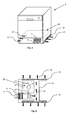
- FIGS. 3 and 4 let recognize a dishwasher 1 equipped with a heat pump device 13.
- the heat pump device 13 essentially has four components, which are fluidically connected to one another via a pipeline system in which a working medium (refrigerant) flows.
- a working medium working medium
- the individual components are arranged so that first an evaporator 17, then a compressor 18 and finally a condenser 19 are flowed through. Subsequently, the refrigerant passes through an expansion device 20 (throttle point) before it is returned to the evaporator 17.
- liquid refrigerant is first injected into the evaporator 17. Due to the low pressure of the refrigerant in the evaporator 17, the refrigerant may evaporate at low temperatures. Subsequently, the compressor 18 sucks the gaseous refrigerant at a low pressure and compresses it to a high pressure. The refrigerant gets hot. The refrigerant thereby contains approximately the sum of the evaporation energy and drive energy of the compressor 18. This energy is released again within the condenser 19. This is done by condensing the refrigerant. Finally, the liquid refrigerant is expanded by means of the restrictor 20 to a low pressure, so that it can evaporate again to pass through the heat pump cycle a second time.
- the evaporator receives the necessary heat energy for evaporating the refrigerant by cooling supply air (i.e., room air), while the condenser releases the heat energy to the dishwashing liquor.
- cooling supply air i.e., room air
- a blower 16 is used, which is connected downstream of the evaporator 17 in the flow direction of the outside air 8, in particular the illustration according to FIG Fig. 4 lets recognize.
- the cooled after passing through the evaporator 7 outside air 8 then passes through an air duct 22 to the side air outlets 15 of the dishwasher 1, through which the cooled outside air 8 leaves the dishwasher 1 as exhaust air 14.
- the problem with a normal operation of the heat pump device 13 is that the surfaces of the evaporator 17 (pipes and fins) are wetted with moisture after switching off the heat pump device 13. Parts of the air duct 22 or of the fan 16 may also have moisture at the end of the program. A sole drying of the surfaces in a nearly closed outer casing is not completely possible.
- FIGS. 5, 6 and 7 show a dishwasher 1 formed in accordance with the invention
- the special feature is that instead of a first blower 7 for the condensation dryer 27 and a second blower 16 for the heat pump device 13 only a single blower 21 is provided as common blower for both the condensation dryer 27 and the heat pump device 13 is provided.
- the fan 16 provided by the heat pump device 13 can preferably be used as a common fan 21.
- the common fan 21 is downstream of an air switching device 24 in the flow direction, which has a rotatably arranged air damper 23 in the illustrated embodiment. Instead of such a damper 23, a slide and / or similar can be provided. Of crucial importance is that by means of the air switching device 24 sucked by the fan 21 outside air 8 as air flow 10 past the Spül matterserwand 26 and / or 14 can be supplied to the air outlet 15 as exhaust air, as this in particular from a synopsis of FIGS. 5 and 6 results.
- This embodiment provides in particular the advantage that can be dispensed with a conventional drying fan. In addition to cost savings, this has the additional advantage that more installation space is available for the heat pump device 13.
- the blower 21 and the evaporator 17 are still partially wetted with moisture. In order to dry these wet components, it is provided according to the invention to leave the blower 21 switched on when the heat pump device 13 is otherwise switched off, or to switch it on again during a later program section.
- the room air 8, which is then no longer cooled in the evaporator 17, can absorb residual moisture and thus the air duct 22, the evaporator 17 and the fan 21 dry.
- the air path of the air conveyed by the fan 21 remains the same as during a heating phase, that is, when the heat pump device 13 is turned on.
- the air duct 22 As the representation after the FIGS. 5 and 6 can recognize, it is preferred to equip the air duct 22 with a pivotable air damper 23.
- This air flap 23 may be formed in the vicinity of the Spül actuallyerwand 26.
- the air flap 23 has a drive, not shown, for this purpose, for example, a wax expansion element, a servomotor, a shape memory metal and / or the like can be used. It can either be provided that only one or only the other airway or that both airways are equally exposed to outside air 8.
- the respective volume flows can be achieved via an adjustment of a corresponding ratio of the two air paths or via a speed control of the blower 21.
- the intended blower 21 may also be upstream of the evaporator 17 in terms of flow, such as the FIG. 8 disclosed.
- the flap 23 When the flap 23 is closed, the heat pump device 13 is in the heating phase, wherein the entire air flow is passed through the evaporator 17. With open flap 23 (as in Fig. 8 shown), a partial flow is passed over the Spülraumwand for condensation drying in the drying phase. The second partial volume flow is used to dry the evaporator.
- the air switching can as in FIGS. 9 and 10 also shown with multiple louvers 23 are implemented. It is also conceivable to actuate a plurality of louvers 23 via only one actuator. This can be implemented, for example, via lever mechanisms known to the person skilled in the art.
Abstract
Description
Die Erfindung betrifft einen Geschirrspülautomaten, insbesondere in der Ausgestaltung als Haushaltsgeschirrspülmaschine, mit einem einen Spülraum bereitstellenden Spülbehälter, einem Kondensationstrockner zur Beaufschlagung einer Spülbehälterwand mit Außenluft und einer Wärmepumpeneinrichtung zur Aufheizung von Spülflotte.The invention relates to a dishwasher, in particular in the embodiment as a domestic dishwasher, with a washing compartment providing a washing compartment, a condensation dryer for acting on a Spülbehälterwand with outside air and a heat pump device for heating of rinsing liquor.
Geschirrspülautomaten der vorgenannten Art sind aus dem Stand der Technik an sich gut bekannt. Sie verfügen über einen Spülbehälter, der seinerseits einen Spülraum bereitstellt. Im bestimmungsgemäßen Verwendungsfall dient der Spülbehälter der Aufnahme von zu reinigendem Spülgut.Dishwashers of the aforementioned type are well known in the art. They have a washing container, which in turn provides a washing room. When used as intended, the washing container serves to receive items to be cleaned.
Der vom Spülbehälter bereitgestellte Spülraum ist verwenderseitig über eine Beschickungsöffnung zugänglich. Diese ist mittels einer verschwenkbar ausgebildeten Spülmaschinentür fluiddicht verschließbar.The washing compartment provided by the washing compartment is accessible to the user via a feed opening. This can be closed fluid-tight by means of a pivotable dishwasher door.
Zur Beschickung des zu reinigenden Spülgutes mit Spülflotte verfügt ein Geschirrspülautomat über eine spülraumseitig ausgebildete Sprüheinrichtung. Diese weist in der Regel zwei oder drei verdrehbar ausgebildete Sprüharme auf, mittels welcher im bestimmungsgemäßen Betrieb von einer Umwälzpumpe geförderte Spülflotte auf das zu reinigende Spülgut gesprüht wird.For loading the items to be cleaned with rinse liquor, a dishwasher has a scavenging chamber side formed spray. This usually has two or three rotatable spray arms, by means of which in the normal operation of a circulating pump funded rinsing water is sprayed onto the items to be cleaned.
Zur Aufheizung der Spülflotte kommen typischerweise elektrische Heizungen zum Einsatz. Es ist aus der
Zur Trocknung von Spülgut nach Abschluss einer bestimmungsgemäßen Reinigung verfügen aus dem Stand der Technik bekannte Geschirrspülautomaten typischerweise über einen Kondensationstrockner. In einer möglichen Ausgestaltung dient dieser der Beaufschlagung einer Spülbehälterwand mit Außenluft, was zu einer Abkühlung der Spülbehälterwand mit der Folge führt, dass im Inneren des Spülbehälters befindliche feuchte Luft an der von außen abgekühlten Spülbehälterwand innenseitig auskondensieren kann. Der im Spülbehälter befindlichen Luft wird so Feuchtigkeit entzogen, was zur Trocknung des am Ende eines bestimmungsgemäß durchlaufenden Spülprogramms noch heißen Spülguts führt.For drying items to be washed after completion of a proper cleaning, automatic dishwashers known from the prior art typically have a condensation dryer. In one possible embodiment, this serves to subject a rinsing container wall to external air, which leads to a cooling of the rinsing container wall, with the result that moist air located in the interior of the rinsing container rests against the outside of the rinsing container wall can condense. The air in the rinsing container is thus deprived of moisture, which leads to the drying of the end of an intended continuous rinse program still hot items.
Obgleich sich vorbeschriebene Geschirrspülautomaten im alltäglichen Praxiseinsatz bewährt haben, besteht Verbesserungsbedarf, insbesondere mit Blick auf einen vereinfachten Aufbau, der hilft, Herstell- und Montagekosten zu senken. Es ist deshalb die Aufgabe der Erfindung, einen neuartigen Geschirrspülautomaten vorzuschlagen.Although the above-described automatic dishwashers have proven themselves in everyday practical use, there is a need for improvement, in particular with a view to a simplified structure that helps to reduce manufacturing and assembly costs. It is therefore the object of the invention to propose a novel dishwasher.
Zur Lösung der vorstehend genannten Aufgabe wird mit der Erfindung vorgeschlagen ein Geschirrspülautomat der eingangs genannten Art, der sich dadurch auszeichnet, dass der Kondensationstrockner und die Wärmepumpeneinrichtung ein gemeinsames Gebläse aufweisen.To achieve the above object, the invention proposes a dishwasher of the type mentioned, which is characterized in that the condensation dryer and the heat pump device have a common blower.
Der aus dem Stand der Technik bekannte Kondensationstrockner verfügt über ein Gebläse. Dieses dient dazu, im Trocknungsfall von außen Raumluft anzusaugen und dieses außenseitig am Spülbehälter an einer Spülbehälterwand vorbei zu führen. In der schon vorbeschriebenen Weise kommt es dabei zu einer Abkühlung der Spülbehälterwand, und zwar mit der Folge, dass im Inneren des Spülbehälters befindliche warmfeuchte Luft innenseitig der abgekühlten Spülbehälterwand auskondensieren kann.The condensation dryer known from the prior art has a blower. This serves to draw in the case of drying from outside room air and this outside on the washing container to lead past a Spülbehälterwand. In the manner already described above, the rinsing container wall is cooled down, with the result that warm moist air located inside the rinsing container can condense on the inside of the cooled rinsing container wall.
Der Geschirrspülautomat weist darüber hinaus eine Wärmepumpeneinrichtung auf, welches gleichfalls über ein Gebläse verfügt. Dieses dient dazu, von außen Raumluft anzusaugen und diese zwecks Wärmeübertragung durch einen Verdampfer hindurchzuführen. Mit der Wärmepumpeneinrichtung wird eine Aufheizung von Spülflotte erreicht, wobei sie der den Geschirrspülautomaten umgebenden Außenluft zur Aufheizung der Spülflotte Wärme entzieht.The dishwasher also has a heat pump device, which also has a fan. This serves to suck in air from the outside and to pass them through for heat transfer through an evaporator. With the heat pump device, a heating of the rinsing liquor is achieved, whereby it extracts heat from the outside air surrounding the automatic dishwasher for heating up the rinsing liquor.
Mit der Erfindung wird nun vorgeschlagen, dass der Kondensationstrockner und die Wärmepumpeneinrichtung ein gemeinsames Gebläse aufweisen, dass der Geschirrspülautomat also anstelle eines ersten Gebläses für den Kondensationstrockner und eines zweiten Gebläses für die Wärmepumpeneinrichtung nur über ein einziges Gebläse verfügt, das dafür geeignet und bestimmt ist, sowohl als Trocknungsgebläse für den Kondensationstrockner als auch als Wärmepumpengebläse für die Wärmepumpeneinrichtung verwendet zu werden. Anstelle von zwei Gebläsen verfügt der erfindungsgemäße Geschirrspülautomat nur über ein einziges Gebläse.With the invention it is now proposed that the condensation dryer and the heat pump device have a common blower, that the dishwashing machine therefore has only one blower, which is suitable and intended for this purpose, instead of a first blower for the condensation dryer and a second blower for the heat pump device, to be used both as a drying fan for the condensation dryer and as a heat pump fan for the heat pump device. Instead of two blowers has the Dishwasher according to the invention only over a single blower.
Die erfindungsgemäße Ausgestaltung ist insofern von Vorteil, als dass auf ein zweites Gebläse vollends verzichtet wird. Dies erbringt eine Kostenersparnis sowohl bei der Herstellung aufgrund der erreichten Bauteilreduzierung als auch bei der Montage. Darüber hinaus ist von Vorteil, dass durch Wegfall eines Gebläses zusätzlicher Bauraum innerhalb des Geschirrspülautomaten zur Verfügung steht, beispielsweise für die Wärmepumpeneinrichtung, was eine optimierte Ausgestaltung derselben ermöglicht.The embodiment according to the invention is advantageous in that it completely dispenses with a second fan. This provides a cost savings both in the production due to the achieved component reduction as well as during assembly. Moreover, it is advantageous that by eliminating a blower additional space is available within the dishwasher, for example, for the heat pump device, which allows an optimized design of the same.
Das erfindungsgemäß vorgesehene Gebläse ist gemäß einem Ausführungsbeispiel einem Verdampfer der Wärmepumpeneinrichtung strömungstechnisch nachgeschaltet. Vom Gebläse angesogene Außenluft passiert demnach automatenseitig zunächst den dem Gebläse strömungstechnisch vorgeschalteten Verdampfer. Bei eingeschalteter Wärmepumpeneinrichtung kommt es im Verdampfer zu einer Abkühlung der Außenluft. Bei ausgeschalteter Wärmepumpeneinrichtung durchströmt die angesogene Außenluft den Verdampfer ohne Temperaturänderung.The fan provided according to the invention is downstream of an evaporator of the heat pump device according to one embodiment. The outside air sucked in by the blower thus first passes through the evaporator, which is upstream of the blower, on the machine side. When the heat pump device is switched on, the outside air in the evaporator cools down. When the heat pump device is switched off, the sucked outside air flows through the evaporator without any temperature change.
In Strömungsrichtung der angesogenen Luft ist dem Gebläse vorzugsweise eine Luftumschaltvorrichtung nachgeschaltet. Mittels dieser Luftumschaltvorrichtung kann die angesogene Luft einem ersten und/oder einem zweiten Strömungsweg zugeführt werden. Gemäß dem ersten Strömungsweg erfolgt ein Ableiten der Luft aus dem Geschirrspülautomaten hinaus; hierfür weist der Geschirrspülautomat Luftabgabeöffnungen auf, bevorzugterweise seitlich und/oder an der Rückwand des Geschirrspülautomaten ausgebildete Luftabgabeöffnungen. Dieser Strömungsweg steht typischerweise bei in Betrieb befindlicher Wärmepumpeneinrichtung zur Verfügung, das heißt während einer Aufheizung von Spülflotte mittels der Wärmepumpeneinrichtung. Die in Folge der Aufheizung der Spülflotte im Verdampfer abgekühlte Außenluft wird über den ersten Strömungsweg abgeführt und aus dem Geschirrspülautomaten geleitet. Der zweite Strömungsweg findet indes bei einer Kondensationstrocknung nach Abschluss eines bestimmungsgemäß durchlaufenden Reinigungsprogramms Verwendung. Die über das Gebläse angesogene Außenluft wird in diesem Fall nicht über die Luftauslässe aus dem Geschirrspülautomaten hinaus abgeleitet. Es findet vielmehr eine automateninterne Umlenkung der Außenluft statt, infolgedessen diese außenseitig einer Spülbehälterwand des Spülbehälters zwecks Abkühlung derselben vorbeiströmt.In the flow direction of the suctioned air, the blower is preferably followed by an air switching device. By means of this air switching device, the sucked air can be supplied to a first and / or a second flow path. According to the first flow path, the air is discharged from the dishwasher; For this purpose, the dishwasher has air discharge openings, preferably air discharge openings formed laterally and / or on the rear wall of the automatic dishwasher. This flow path is typically available when the heat pump device is in operation, that is to say during heating of rinsing liquor by means of the heat pump device. The cooled as a result of heating the rinsing liquor in the evaporator outside air is removed via the first flow path and directed out of the dishwasher. The second flow path, however, is used in a condensation drying after completion of an intended continuous cleaning program use. In this case, the outside air sucked in via the blower will not be drained out of the dishwasher through the air outlets. Rather, there is an automatic internal deflection of the outside air, as a result, this flows outside of a Spülbehälterwand the Spülbehälters for the purpose of cooling the same.
Es kann alternativ zum Vorbeschriebenen auch vorgesehen sein, dass beide Strömungswege gleichzeitig zumindest teilweise geöffnet sind, mithin die vom Gebläse geförderte Luft sowohl über den ersten Strömungsweg über die, insbesondere seitlich und/oder an der Rückwand des Geschirrspülautomaten ausgebildeten, Luftabgabeöffnungen abgeleitet als auch über den zweiten Strömungsweg an einer Spülbehälterwand außenseitig vorbei geleitet wird. Dabei ist das Verhältnis der auf die beiden Strömungswege aufgeteilten Luftmengen vorzugsweise einstellbar und kann beispielsweise in Abhängigkeit des gewünschten Kühleffektes der Spülbehälterwand frei gewählt werden.As an alternative to the above, it can also be provided that both flow paths are at least partially opened at the same time, ie the air conveyed by the fan is diverted both via the first flow path via the air discharge openings, in particular laterally and / or on the rear wall of the automatic dishwashing machine, as well as via the second flow path is passed to a Spülbehälterwand outside on the outside. In this case, the ratio of the amounts of air distributed over the two flow paths is preferably adjustable and can be freely selected, for example, depending on the desired cooling effect of the washing compartment wall.
Die Luftumschaltvorrichtung weist vorzugsweise eine Luftklappe auf, mit der ein Strömungsweg, insbesondere der zweite Strömungsweg, wahlweise geöffnet oder geschlossen werden kann, die Luftklappe kann insbesondere verschwenkbar ausgebildet sein. Es können auch zwei Luftklappen, nämlich für den ersten und den zweiten Strömungsweg jeweils eine derartige Luftklappe vorhanden sein. Alternativ kann lediglich eine Luftklappe vorhanden sein, die beiden Strömungswegen zugeordnet ist, und die bei geschlossenem ersten Strömungweg den zweiten Strömungsweg freigibt und umgekehrt.The air switching device preferably has an air flap, with which a flow path, in particular the second flow path, can optionally be opened or closed, the air flap can in particular be designed to be pivotable. It can also be two louvers, namely for the first and the second flow path in each case such a damper be present. Alternatively, only one air flap may be present, which is assigned to both flow paths, and which releases the second flow path when the first flow path is closed, and vice versa.
Die erfindungsgemäße Verwendung nur eines Gebläses erfüllt verfahrensseitig zudem den Vorteil, dass bei ansonsten ausgeschalteter Wärmepumpeneinrichtung ein Nachlauf des Gebläses zwecks Trocknung des durch Kondensat unter Umständen feuchten Verdampfers der Wärmepumpeneinrichtung gestattet ist. Dabei findet ein solches Trocknen des Verdampfers bevorzugterweise dann statt, wenn das Gebläse zwecks Kondensationstrocknung ohnehin in Betrieb ist. Der Einsatz nur eines Gebläses bietet insofern einen synergetischen Effekt, als dass einerseits durch die Luftförderung eine Trocknung des Verdampfers als auch andererseits durch Abkühlung einer Spülbehälterwand eine Kondensationstrocknung des Spülgutes erreicht wird. Dieser synergetische Effekt ergibt sich bei aus dem Stand der Technik vorbekannten Geschirrspülautomaten nicht.The use of only one blower according to the invention also has the advantage on the process side that, with the heat pump device otherwise switched off, the blower may be allowed to run for drying of the evaporator, which may be humid by condensation, of the heat pump device. In this case, such drying of the evaporator preferably takes place when the blower is already in operation for the purpose of condensation drying. The use of only one fan offers a synergistic effect in that on the one hand by the air promotion drying of the evaporator and on the other hand by cooling a Spülbehälterwand a condensation drying of the dishes is achieved. This synergistic effect does not arise in previously known from the prior art automatic dishwashers.
Unabhängig zum vorbeschriebenen Geschirrspülautomaten wird mit der Erfindung deshalb verfahrensseitig ferner vorgeschlagen ein Verfahren zum Betrieb eines mit einer Wärmepumpeneinrichtung ausgerüsteten Geschirrspülautomaten, bei dem in einer Aufheizphase Spülflotte in einem Verflüssiger erwärmt und die dazu in einem Verdampfer abgekühlte Außenluft mittels eines Gebläses abgeleitet wird und bei dem in einer Trocknungsphase das Gebläse bei ansonsten ausgeschalteter Wärmepumpeneinrichtung weiter betrieben wird.Regardless of the above-described automatic dishwashers, the invention therefore further proposes a process for operating a dishwashing machine equipped with a heat pump device in which rinsing liquor is heated in a condenser in a heating phase and the outside air cooled in an evaporator is diverted by means of a blower and in which one Drying phase, the fan is operated with otherwise switched off heat pump device on.
Nach der erfindungsgemäßen Verfahrensdurchführung erfolgt in an sich bekannter Weise ein bestimmungsgemäßer Betrieb der Wärmepumpeneinrichtung, demgemäß es zu einer Abkühlung von außen angesogener Raumluft kommt. Diese abgekühlte Raumluft wird mittels des Gebläses abgeleitet. Sobald die Spülflotte mittels der Wärmepumpeneinrichtung in bestimmungsgemäßer Weise erwärmt ist, erfolgt eine Abschaltung der Wärmepumpeneinrichtung. Erfindungsgemäß ist nun vorgesehen, dass das Gebläse der Wärmepumpeneinrichtung bei ansonsten ausgeschalteter Wärmepumpeneinrichtung weiter betrieben wird. In vorteilhafter Weise wird so erreicht, dass durch den Verdampfer nach wie vor von außen angesogene Außenluft geführt wird. Dies führt in vorteilhafter Weise dazu, dass sich im Verdampfer unter Umständen angesammeltes Kondensat von der hindurchgeführten Außenluft mitgenommen, das heißt eine Abtrocknung des Verdampfers erreicht wird. Es wird so sichergestellt, dass es nicht aufgrund von Restfeuchte zu einer Verkeimung des Verdampfers mit einhergehender Geruchsbelästigung kommt. Die erfindungsgemäße Verfahrensdurchführung stellt vielmehr eine Abtrocknung des Verdampfers nach einem bestimmungsgemäßen Einsatz sicher.After carrying out the method according to the invention, a proper operation of the heat pump device takes place in a manner known per se, according to which there is a cooling of room air sucked in from outside. This cooled room air is discharged by means of the blower. As soon as the rinsing liquor is heated in the intended manner by means of the heat pump device, the heat pump device is switched off. According to the invention, it is now provided that the fan of the heat pump device is operated while the heat pump device is otherwise switched off. Advantageously, it is achieved that is still performed by the evaporator from outside sucked outside air. This leads advantageously to the fact that in the evaporator possibly accumulated condensate taken from the outside air passed through, that is, a drying of the evaporator is achieved. It is thus ensured that it does not come due to residual moisture to a contamination of the evaporator with an associated odor nuisance. Rather, the process implementation according to the invention ensures that the evaporator dries off after use as intended.
Gemäß einem weiteren Merkmal der Erfindung folgt der ersten Trocknungsphase eine weitere Trocknungsphase nach, wobei in der weiteren Trocknungsphase eine Spülbehälterwand mit der vom Gebläse geförderten Außenluft beaufschlagt wird. Gemäß dieser weiteren Trocknungsphase erfolgt also in an sich bekannter Weise eine Kondensationstrocknung des vom Spülbehälter aufgenommenen Spülguts.According to a further feature of the invention, the first drying phase is followed by a further drying phase, wherein in the further drying phase a rinsing container wall is charged with the outside air conveyed by the blower. According to this further drying phase, condensation drying of the items to be washed picked up by the washing container thus takes place in a manner known per se.
Dem Gebläse ist in Strömungsrichtung der Außenluft eine Luftumschaltvorrichtung nachgeschaltet, mittels der die vom Gebläse geförderte Außenluft gemäß einem weiteren Merkmal der Erfindung wahlweise auf unterschiedliche Strömungswege verteilt wird. Die Verteilung der vom Gebläse geförderten Außenluft auf einen ersten und/oder einen zweiten Strömungsweg erbringt die schon vorerläuterten Vorteile.The blower is followed by an air switching device in the flow direction of the outside air, by means of which the outside air conveyed by the blower is optionally distributed to different flow paths according to a further feature of the invention. The distribution of the outside air conveyed by the fan to a first and / or a second flow path provides the already vorerläuterten advantages.
Vorzugsweise kann das Gebläse mit einer ersten Drehzahl und mit einer gegenüber der ersten Drehzahl niedrigeren, insbesonders wesentlich niedrigeren Drehzahl betrieben werden, insbesondere ist das Gebläse drehzahlregelbar. Das Gebläse wird bei Betrieb der Wärmepumpeneinrichtung, also in einer Spülflottenaufheizphase, mit der ersten Drehzahl betrieben, wobei ein Volumenstrom von mindestens 50m3/h gefördert wird. Bei abgeschalteter Wärmepumpeneinrichtung, also während der ersten und/oder der weiteren Trocknungsphase, wird das Gebläse dagegen mit reduzierter Drehzahl betrieben, wodurch ein energetisch besonders effizienter Betrieb des Geschirrspülautomaten gewährleistet ist.Preferably, the fan can be operated at a first speed and with respect to the first speed lower, in particular substantially lower speed, in particular the fan is speed controlled. The blower is operated during operation Heat pump device, ie in a Spülflottenaufheizphase, operated at the first speed, wherein a volume flow of at least 50m 3 / h is promoted. When the heat pump device is switched off, that is, during the first and / or the further drying phase, the fan is operated at a reduced speed, whereby an energetically particularly efficient operation of the automatic dishwasher is ensured.
Weitere Merkmale und Vorteile der Erfindung ergeben sich aus der nachfolgenden Beschreibung anhand der Figuren. Dabei zeigen:
- Fig. 1
- in schematisch perspektivischer Ansicht einen Geschirrspülautomaten mit einer Kondensationstrocknung;
- Fig.2
- in einer schematischen Frontansicht den Geschirrspülautomaten nach
Fig. 1 ; - Fig. 3
- in schematisch perspektivischer Ansicht einen Geschirrspülautomaten mit einer Wärmepumpeneinrichtung;
- Fig. 4
- in einer schematischen Draufsicht von oben die Wärmepumpeneinrichtung des Geschirrspülautomaten nach
Fig. 3 ; - Fig. 5
- in einer schematischen Seitenansicht einen Geschirrspülautomaten nach der Erfindung mit einer in einer Aufheizphase befindlichen Wärmepumpeneinrichtung;
- Fig. 6
- in einer schematischen Seitenansicht einen Geschirrspülautomaten nach der Erfindung mit einer in einer Trocknungsphase befindlichen Wärmepumpeneinrichtung;
- Fig. 7
- in schematischer Frontansicht den Geschirrspülautomaten nach
Fig. 6 . - Fig. 8
- in einer schematischen Seitenansicht eine weitere Ausgestaltungsform mit dem Verdampfer strömungstechnisch vorgeschaltetem Gebläse
- Fig. 9
- eine weitere Ausgestaltung der Luftwegumschaltung nach der Erfindung mit einer in einer Aufheizphase befindlichen Wärmepumpeneinrichtung;
- Fig. 10
- eine weitere Ausgestaltung der Luftwegumschaltung nach der Erfindung mit einer in einer Trocknungsphase befindlichen Wärmepumpeneinrichtung
- Fig. 1
- in a schematic perspective view of a dishwasher with a condensation drying;
- Fig.2
- in a schematic front view of the dishwasher after
Fig. 1 ; - Fig. 3
- in a schematic perspective view of a dishwasher with a heat pump device;
- Fig. 4
- in a schematic plan view from above the heat pump device of the dishwasher after
Fig. 3 ; - Fig. 5
- in a schematic side view of a dishwasher according to the invention with a heat pump in a heat pumping device;
- Fig. 6
- in a schematic side view of a dishwasher according to the invention with a located in a drying phase heat pump device;
- Fig. 7
- in a schematic front view of the dishwasher after
Fig. 6 , - Fig. 8
- in a schematic side view of another embodiment with the evaporator fluidly upstream blower
- Fig. 9
- a further embodiment of the airway switching according to the invention with a heat pump in a heat pumping device;
- Fig. 10
- a further embodiment of the airway switching according to the invention with a heat pump in a drying phase device
Der Geschirrspülautomat 1 verfügt über ein Außengehäuse 2. Diese nimmt einen Spülbehälter 25 auf, der einen Spülraum 6 bereitstellt. Der Spülbehälter 25 ist frontseitig mittels einer Beschickungsöffnung zugänglich, die mittels einer verschwenkbar angeordneten Tür 3 fluiddicht verschließbar ist.The
Die Tür 3 verfügt mit Bezug auf die Zeichnungsebene nach
Oberseitig des Außengehäuses 2 ist im endmontierten Zustand eine Abdeckplatte 12, beispielsweise in der Ausgestaltung einer Arbeitsplatte angeordnet, wie insbesondere die Darstellung nach
Der Geschirrspülautomat 1 verfügt über einen Kondensationstrockner 27. Dieser weist ein Gebläse 7 auf, das über den Lufteinlass 9 Außenluft 8 ansaugt. Die angesogene Außenluft 8 wird als Luftstrom 10 an der Spülbehälterwand 26 des Spülbehälters 25 vorbeigeführt und wird oberseitig des Spülbehälters 25 als Abluft 11 an die den Geschirrspülautomaten 1 umgebende Atmosphäre wieder abgegeben. Dort kann die durch das Vorbeiströmen an dem warmen Spülbehälter erwärmte Abluft 11 insbesondere dazu dienen, eine angrenzende Küchenarbeitplatte vorzuwärmen und ein Luftpolster bereitzustellen, der verhindert, dass bei einer Öffnung der Spülbehältertür 3 austretende Wrasen an der Küchenarbeitsplatte kondensieren.The
Im bestimmungsgemäßen Einsatzfall erfolgt zum Abschluss eines Reinigungsprogramms ein Klarspülen. Die Spülflotte und damit auch das vom Spülbehälter 25 aufgenommene Spülgut werden dabei auf beispielsweise 55°C aufgewärmt. Durch Zugabe eines Klarspülmittels wird die Oberflächenspannung der Spülflotte herabgesetzt. Zum Ende des Klarspülens wird die Spülflotte abgepumpt. In einer Abtropfphase kann Restfeuchtigkeit vom Spülgut und den im Spülbehälter befindlichen Körben zur Aufnahme von Spülgut abtropfen beziehungsweise ablaufen, was durch die niedrige Oberflächenspannung begünstigt wird. Die Eigenwärme des Spülguts lässt den noch zurückbleibenden Wasserfilm verdunsten. Die Spülraumluft sättigt sich folglich allmählich mit Wasserdampf. Ist die Spülraumluft gesättigt, kann kein weiteres Wasser vom Spülgut und den Körben abtrocknen. Um die Feuchtigkeit in der Spülraumluft zu senken und somit wieder aufnahmefähig zu machen, wird eine Spülbehälterwand 26 des Spülbehälters 25 mit einem Luftstrom 10 in der schon vorbeschriebenen Weise gekühlt. Die Temperatur der Spülraumwand 26 sinkt und somit wird der Taupunkt der feuchten Spülraumluft unterschritten. Der Wasserdampf in der gesättigten Spülraumluft kann an der Spülraumwand 26 kondensieren. Die Spülraumluft ist nicht mehr gesättigt und kann somit wieder Feuchtigkeit aufnehmen.When used as intended, rinsing takes place at the end of a cleaning program. The rinsing liquor and thus also the rinse
Die
Die Wärmepumpeneinrichtung 13 verfügt im Wesentlichen über vier Bauteile, die strömungstechnisch über ein Rohrleitungssystem miteinander verbunden sind, in welchem ein Arbeitsmedium (Kältemittel) strömt. In Strömungsrichtung des Kältemittels sind die einzelnen Bauteile so angeordnet, dass zuerst ein Verdampfer 17, anschließend ein Verdichter 18 und schließlich ein Verflüssiger 19 durchströmt werden. Anschließend durchläuft das Kältemittel eine Expansionseinrichtung 20 (Drosselstelle) bevor es wieder dem Verdampfer 17 zugeführt wird.The
Für den Betrieb des Wärmepumpenkreislaufes wird zuerst flüssiges Kältemittel in den Verdampfer 17 eingespritzt. Aufgrund des niedrigen Drucks des Kältemittels im Verdampfer 17 kann das Kältemittel bei Niedrigtemperaturen verdampfen. Anschließend saugt der Verdichter 18 das gasförmige Kältemittel mit niedrigem Druck an und verdichtet es auf einen hohen Druck. Dabei wird das Kältemittel heiß. Das Kältemittel beinhaltet dadurch ungefähr die Summe der Verdampfungsenergie und Antriebsenergie des Verdichters 18. Diese Energie wird innerhalb des Verflüssigers 19 wieder abgegeben. Dies geschieht durch das Kondensieren des Kältemittels. Schließlich wird das flüssige Kältemittel mittels der Drosselstelle 20 auf einen niedrigen Druck expandiert, so dass es wieder verdampfen kann, um den Wärmepumpenkreislauf ein weiteres Mal zu durchlaufen.For the operation of the heat pump cycle, liquid refrigerant is first injected into the
Damit dieser Wärmepumpenkreislauf funktioniert, muss dem Verdampfer Wärmeenergie zur Verfügung gestellt und dem Verflüssiger Wärme entzogen werden. Der Verdampfer erhält dabei wie zuvor beschrieben die notwendige Wärmeenergie zur Verdampfung des Kältemittels durch das Abkühlen von Zuluft (d.h. Raumluft), während der Verflüssiger die Wärmeenergie an Spülflotte der Geschirrspülmaschine abgibt.For this heat pump cycle to work, heat energy must be made available to the evaporator and heat must be removed from the condenser. As described above, the evaporator receives the necessary heat energy for evaporating the refrigerant by cooling supply air (i.e., room air), while the condenser releases the heat energy to the dishwashing liquor.
Zur Beschickung des Verdampfers 17 mit Außenluft 8 kommt ein Gebläse 16 zum Einsatz, das in Strömungsrichtung der Außenluft 8 dem Verdampfer 17 nachgeschaltet ist, wie insbesondere die Darstellung nach
Infolge der Abkühlung der Außenluft 8 bei einem bestimmungsgemäßen Betrieb der Wärmepumpeneinrichtung 13 kann es zu einem Auskondensieren von Luftfeuchtigkeit kommen, die sich im Verdampfer 17, im Luftkanal 22 und im Gebläse 16 niederschlagen und ansammeln kann. Dieses anfallende Kondensat wird in einer dafür vorgesehenen Auffangwanne gesammelt und entweder verworfen oder in einem Spülprozess verwendet.As a result of the cooling of the
Problematisch bei einem auch bestimmungsgemäßen Betrieb der Wärmepumpeneinrichtung 13 ist, dass die Oberflächen des Verdampfers 17 (Rohre und Lamellen) nach einem Abschalten der Wärmepumpeneinrichtung 13 mit Feuchtigkeit benetzt sind. Auch Teile des Luftkanals 22 oder des Lüfters 16 können zum Programmende Feuchtigkeit aufweisen. Ein alleiniges Abtrocknen der Oberflächen in einem nahezu geschlossenen Außengehäuse ist nicht vollständig möglich.The problem with a normal operation of the
Insbesondere bei langen Stillstandzeiten können aufgrund der mit Feuchtigkeit benetzten Oberflächen Bakterien, Keime und/oder dergleichen Anhaftungen entstehen. Diese können zu einer ungewollten Geruchsbildung führen, was verwenderseitig als unangenehm und mithin als nachteilig empfunden wird.Especially with long downtimes due to the wetted surfaces with moisture bacteria, germs and / or the like buildup can occur. These can lead to an unwanted odor, which is perceived by the user as unpleasant and therefore disadvantageous.
Die
Dem gemeinsamen Gebläse 21 ist in Strömungsrichtung eine Luftumschaltvorrichtung 24 nachgeschaltet, die im gezeigten Ausführungsbeispiel über eine verdrehbar angeordnete Luftklappe 23 verfügt. Anstelle einer solchen Luftklappe 23 kann auch ein Schieber und/oder vergleichbares vorgesehen sein. Von entscheidender Bedeutung ist, dass mittels der Luftumschaltvorrichtung 24 die vom Gebläse 21 angesogene Außenluft 8 als Luftstrom 10 an der Spülbehälterwand 26 vorbeigeführt und/oder als Abluft 14 dem Luftauslass 15 zugeführt werden kann, wie sich dies insbesondere aus einer Zusammenschau der
Bei einem Betrieb der Wärmepumpeneinrichtung 13 wird während einer Aufheizphase Spülflotte durch den Verflüssiger 19 erwärmt und die abgekühlte Raumluft 14 über einen Luftauslass 15 aus dem Automaten 1 abgeleitet. Nach einem Abschalten des Verdichters 18 sind der Luftkanal 22, das Gebläse 21 und der Verdampfer 17 noch teilweise mit Feuchtigkeit benetzt. Um diese nassen Komponenten abzutrocknen, ist erfindungsgemäß vorgesehen, das Gebläse 21 bei ansonsten ausgeschalteter Wärmepumpeneinrichtung 13 eingeschaltet zu lassen oder während eines späteren Programmabschnitts wieder einzuschalten. Die Raumluft 8, die dann im Verdampfer 17 nicht mehr abgekühlt wird, kann Restfeuchte aufnehmen und somit den Luftkanal 22, den Verdampfer 17 und das Gebläse 21 abtrocknen. Dabei bleibt der Luftweg der vom Gebläse 21 geförderten Raumluft der gleiche wie auch während einer Aufheizphase, das heißt bei eingeschalteter Wärmepumpeneinrichtung 13.During operation of the
Mittels der schon vorbeschriebenen Luftumschaltvorrichtung 24 kann eine Umschaltung des Luftweges stattfinden. Hierdurch ist es ermöglicht, trotz im Unterschied zum Stand der Technik nicht mehr vorhandenem Trocknungsgebläse 7 eine Kondensationstrocknung durchzuführen, indem nämlich die vom Gebläse 21 geförderte Luft als Luftstrom 10 an der Spülbehälterwand 26 vorbeigeführt wird.By means of the above-described
Wie die Darstellung nach den
Typischerweise werden während einer Aufheizphase der Wärmepumpeneinrichtung ein Volumenstrom von 50-150 m3/h, bevorzugt 70 m3/h mittels des Gebläses gefördert, während für die Kondensationstrocknung typischerweise ein kleinerer Volumenstrom (10-50 m3/h, bevorzugt 30 m3/h) ausreicht. Die jeweiligen Volumenströme können über eine Einstellung eines entsprechenden Verhältnisses der beiden Luftwege oder über eine Drehzahlregelung des Gebläses 21 erreicht werden.Typically, during a heating phase of the heat pump device, a volume flow of 50-150 m 3 / h, preferably 70 m 3 / h promoted by the blower, while for the condensation drying typically a smaller volume flow (10-50 m 3 / h, preferably 30 m 3 / h) is sufficient. The respective volume flows can be achieved via an adjustment of a corresponding ratio of the two air paths or via a speed control of the
In einer weiteren Ausgestaltung kann das vorgesehene Gebläse 21 auch dem Verdampfer 17 strömungstechnisch vorgeschaltet sein, wie die
Die Luftumschaltung kann wie in
Ein möglicher Verfahrensablauf stellt sich wie folgt dar:
- Es findet zunächst ein Aufheizen der Spülflotte mittels der Wärmepumpeneinrichtung 13 statt.
Der Verdichter 18der Wärmepumpeneinrichtung 13 wird nach erfolgter Aufheizung ausgeschaltet. Es werden die weiteren Spülphasen wie zum Beispiel das Zwischenspülen oder das Klarspülen mit oder ohne Aufheizphasen durchgeführt.Bei ausgeschaltetem Verdichter 18der Wärmepumpeneinrichtung 13 erfolgt dann eine Einschaltung des Gebläses 21, wodurch eine Trocknung des Gebläses 21, desLuftkanals 22 und des Verdampfers 17 stattfindet. In einem weiteren Trocknungsschritt startet dann die Trocknung des gereinigten Spülgutes durch Kondensationstrocknung, zu welchem Zweck der zweite Luftweg geöffnet und dievom Gebläse 21geförderte Außenluft 8 als Luftstrom 10 ander Spülbehälterwand 26 vorbeigeführt wird. Bei gleichzeitigem Öffnen beider Strömungswege kann gemäß einer alternativen Durchführung gleichzeitig eine Spülguttrocknung durch Kondensationstrocknung und eineTrocknung von Verdampfer 17,Gebläse 21 undLuftkanal 22 stattfinden.
- There is first a heating of the rinsing liquor by means of the
heat pump device 13 instead. Thecompressor 18 of theheat pump device 13 is turned off after heating. The further rinsing phases, such as, for example, intermediate rinsing or rinsing with or without heating phases, are carried out. When thecompressor 18 of theheat pump device 13 is turned off then an activation of theBlower 21, whereby a drying of theblower 21, theair channel 22 and theevaporator 17 takes place. In a further drying step then starts the drying of the cleaned items to be cleaned by condensation drying, for which purpose the second airway opened and theoutside air 8 conveyed by thefan 21 is guided past theSpülbehälterwand 26 asair flow 10. With simultaneous opening of both flow paths can take place according to an alternative implementation simultaneously a Spülguttrocknung by condensation drying and drying ofevaporator 17,fan 21 andair duct 22.
Insgesamt ergeben sich mit der erfindungsgemäßen Ausgestaltung damit Bauraum- und Kostenvorteile, da ein kombiniertes Gebläse 21 sowohl für die Wärmepumpeneinrichtung 13 als auch für den Kondensationstrockner 27 zum Einsatz kommt. Darüber hinaus kann eine Zeit- und Energieersparnis bei der Verfahrensdurchführung erreicht werden, da ein gleichzeitiges Trocknen sowohl von Spülgut als auch von Verdampfer 17, Gebläse 21 und Luftkanal 22 stattfinden kann.Overall, with the embodiment according to the invention thus resulting space and cost advantages, since a combined
- 11
- Geschirrspülautomatdishwasher
- 22
- Außengehäuseouter casing
- 33
- Türdoor
- 44
- Blendecover
- 55
- Sockelbereichplinth
- 66
- SpülraumWash cabinet
- 77
- Gebläsefan
- 88th
- Außenluft (Raumluft)Outside air (room air)
- 99
- Lufteinlassair intake
- 1010
- Luftstromairflow
- 1111
- Abluftexhaust
- 1212
- Abdeckplattecover
- 1313
- WärmepumpeneinrichtungA heat pump apparatus
- 1414
- Abluftexhaust
- 1515
- Luftauslassair outlet
- 1616
- Gebläsefan
- 1717
- VerdampferEvaporator
- 1818
- Verdichtercompressor
- 1919
- Verflüssigercondenser
- 2020
- Expansionseinrichtungexpander
- 2121
- Gebläsefan
- 2222
- Luftkanalair duct
- 2323
- Luftklappedamper
- 2424
- LuftumschaltvorrichtungLuftumschaltvorrichtung
- 2525
- Spülbehälterrinse tank
- 2626
- Spülbehälterwandwashing tub
- 2727
- Kondensationstrocknercondensation dryer
Claims (9)
dass der Kondensationstrockner (27) und die Wärmepumpeneinrichtung (13) ein gemeinsames Gebläse (21) aufweisen.Dishwasher, in particular domestic dishwasher, with a rinsing container (25) providing a rinsing chamber (6), a condensation drier (27) for exposing a rinsing container wall (26) to outside air and a heat pump device (13) for heating rinsing liquor, characterized
in that the condensation dryer (27) and the heat pump device (13) have a common blower (21).
Applications Claiming Priority (1)
| Application Number | Priority Date | Filing Date | Title |
|---|---|---|---|
| DE102013101861.0A DE102013101861A1 (en) | 2013-02-26 | 2013-02-26 | Dishwasher, in particular household dishwasher |
Publications (3)
| Publication Number | Publication Date |
|---|---|
| EP2777471A2 true EP2777471A2 (en) | 2014-09-17 |
| EP2777471A3 EP2777471A3 (en) | 2015-01-07 |
| EP2777471B1 EP2777471B1 (en) | 2017-11-22 |
Family
ID=50156715
Family Applications (1)
| Application Number | Title | Priority Date | Filing Date |
|---|---|---|---|
| EP14401019.6A Active EP2777471B1 (en) | 2013-02-26 | 2014-02-04 | Dishwasher, in particular household dishwasher |
Country Status (3)
| Country | Link |
|---|---|
| US (1) | US9468355B2 (en) |
| EP (1) | EP2777471B1 (en) |
| DE (1) | DE102013101861A1 (en) |
Cited By (3)
| Publication number | Priority date | Publication date | Assignee | Title |
|---|---|---|---|---|
| CN105982631A (en) * | 2015-02-04 | 2016-10-05 | 青岛海尔洗碗机有限公司 | Dishwasher condensation drying system, condensation drying method and dishwasher |
| EP3731720A4 (en) * | 2017-12-25 | 2021-09-15 | Arçelik Anonim Sirketi | A heat pump dishwasher |
| EP3731718A4 (en) * | 2017-12-25 | 2021-09-15 | Arçelik Anonim Sirketi | A heat pump dishwasher |
Families Citing this family (22)
| Publication number | Priority date | Publication date | Assignee | Title |
|---|---|---|---|---|
| DE102015113352A1 (en) | 2014-09-23 | 2016-03-24 | Fischerwerke Gmbh & Co. Kg | Fixing systems with finely divided fillers |
| WO2016089332A1 (en) * | 2014-12-03 | 2016-06-09 | Arcelik Anonim Sirketi | A heat pump dishwasher |
| CN104825111B (en) * | 2015-04-24 | 2017-11-10 | 佛山市顺德区美的洗涤电器制造有限公司 | Dishwasher drying system |
| KR102124926B1 (en) * | 2015-11-30 | 2020-07-07 | 삼성전자주식회사 | Air blower and dish washer having the same |
| US20170202424A1 (en) * | 2016-01-20 | 2017-07-20 | General Electric Company | Methods for Operating Dishwasher Appliances Having Energy Recovery Features |
| DE102016103921A1 (en) | 2016-03-04 | 2017-09-07 | Miele & Cie. Kg | dishwasher |
| US9907451B2 (en) | 2016-05-09 | 2018-03-06 | Samsung Electronics Co., Ltd. | Dishwasher drying system with thermal storage heat exchanger |
| KR102373181B1 (en) | 2017-05-26 | 2022-03-11 | 삼성전자주식회사 | Dish washer |
| US20190133412A1 (en) * | 2017-11-06 | 2019-05-09 | Haier Us Appliance Solutions, Inc. | Heating assembly for a washing appliance |
| CN109938656B (en) * | 2017-12-21 | 2022-03-29 | 青岛海尔洗碗机有限公司 | Heat pump type dish washing machine and control method |
| CN108451468B (en) * | 2018-03-26 | 2023-08-29 | 佛山市顺德区美的洗涤电器制造有限公司 | Washing electric appliance |
| EP3775354A1 (en) | 2018-04-02 | 2021-02-17 | Arçelik Anonim Sirketi | A washer with heat pump |
| US10506912B2 (en) * | 2018-05-16 | 2019-12-17 | Haier Us Appliance Solutions, Inc. | Dishwasher appliance with vent duct mixing |
| CN108937796A (en) * | 2018-09-14 | 2018-12-07 | 佛山市顺德区美的洗涤电器制造有限公司 | Wash electric appliance |
| ES2756875A1 (en) * | 2018-10-25 | 2020-04-27 | Bsh Electrodomesticos Espana Sa | Avoid condensation of water vapor on the exterior wall of a domestic dishwasher. (Machine-translation by Google Translate, not legally binding) |
| DE102019108883A1 (en) * | 2019-04-04 | 2020-10-08 | Miele & Cie. Kg | Dishwasher, in particular household dishwasher |
| TR201908884A2 (en) * | 2019-06-14 | 2020-12-21 | Arcelik As | A DISHWASHER WITH A HEAT PUMP |
| DE102020100433A1 (en) * | 2020-01-10 | 2021-07-15 | Miele & Cie. Kg | Dishwasher, in particular household dishwasher |
| IL277571B (en) * | 2020-09-24 | 2021-01-31 | Kvitko Sergei | Dishwasher with a cooling function |
| DE102020212345A1 (en) * | 2020-09-30 | 2022-03-31 | BSH Hausgeräte GmbH | Household dishwasher with at least one air outlet |
| US11672404B2 (en) * | 2020-10-07 | 2023-06-13 | Whirlpool Corporation | Dish treating appliance with an air supply circuit |
| US20230046683A1 (en) * | 2021-08-11 | 2023-02-16 | Whirlpool Corporation | Air barrier for door condensation |
Citations (1)
| Publication number | Priority date | Publication date | Assignee | Title |
|---|---|---|---|---|
| DE102011000042A1 (en) | 2011-01-05 | 2012-07-05 | Miele & Cie. Kg | Method for carrying out a washing program |
Family Cites Families (10)
| Publication number | Priority date | Publication date | Assignee | Title |
|---|---|---|---|---|
| DE3418304A1 (en) * | 1984-05-17 | 1985-11-21 | Miele & Cie GmbH & Co, 4830 Gütersloh | Dish-washing machine |
| DE4230576C2 (en) * | 1992-09-12 | 1996-06-13 | Aeg Hausgeraete Gmbh | Dishwasher with a blower device |
| DE4330456C1 (en) * | 1993-09-08 | 1995-03-16 | Blomberg Werke Gmbh | Tumble dryer |
| EP1447042B1 (en) * | 2003-02-11 | 2007-04-25 | Whirlpool Corporation | Dishwasher with drying system |
| KR101122830B1 (en) * | 2004-10-12 | 2012-03-21 | 엘지전자 주식회사 | A condensing apparatus of a dish washer |
| JP4670595B2 (en) * | 2005-11-04 | 2011-04-13 | パナソニック株式会社 | Dishwasher |
| EP1961361B1 (en) * | 2007-02-20 | 2011-02-16 | Electrolux Home Products Corporation N.V. | Drying system for a dishwasher |
| US7909939B2 (en) * | 2007-04-25 | 2011-03-22 | Illinois Tool Works, Inc. | Humidity reducing exhaust duct for dishwasher |
| TW200916042A (en) * | 2007-10-11 | 2009-04-16 | Panasonic Corp | Dish washing/drying machine |
| KR101481566B1 (en) * | 2008-08-21 | 2015-01-13 | 엘지전자 주식회사 | Controlling method for dishwasher |
-
2013
- 2013-02-26 DE DE102013101861.0A patent/DE102013101861A1/en not_active Withdrawn
-
2014
- 2014-02-04 EP EP14401019.6A patent/EP2777471B1/en active Active
- 2014-02-24 US US14/187,350 patent/US9468355B2/en active Active
Patent Citations (1)
| Publication number | Priority date | Publication date | Assignee | Title |
|---|---|---|---|---|
| DE102011000042A1 (en) | 2011-01-05 | 2012-07-05 | Miele & Cie. Kg | Method for carrying out a washing program |
Cited By (3)
| Publication number | Priority date | Publication date | Assignee | Title |
|---|---|---|---|---|
| CN105982631A (en) * | 2015-02-04 | 2016-10-05 | 青岛海尔洗碗机有限公司 | Dishwasher condensation drying system, condensation drying method and dishwasher |
| EP3731720A4 (en) * | 2017-12-25 | 2021-09-15 | Arçelik Anonim Sirketi | A heat pump dishwasher |
| EP3731718A4 (en) * | 2017-12-25 | 2021-09-15 | Arçelik Anonim Sirketi | A heat pump dishwasher |
Also Published As
| Publication number | Publication date |
|---|---|
| US20140238450A1 (en) | 2014-08-28 |
| EP2777471A3 (en) | 2015-01-07 |
| US9468355B2 (en) | 2016-10-18 |
| EP2777471B1 (en) | 2017-11-22 |
| DE102013101861A1 (en) | 2014-08-28 |
Similar Documents
| Publication | Publication Date | Title |
|---|---|---|
| EP2777471B1 (en) | Dishwasher, in particular household dishwasher | |
| EP1791459B1 (en) | Drying method for a household appliance and household appliance | |
| EP1737334B1 (en) | Rinsing method of a dishwasher, and dishwasher | |
| EP2322072B1 (en) | Dishwasher with a latent heat reservoir | |
| DE102008054548A1 (en) | Dryer with recirculating air and process for its operation | |
| EP1696783B1 (en) | Dishwasher | |
| DE10353774A1 (en) | Drying items in domestic dish washing machines has a reversible hydroscopic material filled column through which recirculated air is driven by a fan | |
| WO2005018409A1 (en) | Dishwasher | |
| WO2018077635A1 (en) | Dishwasher having a heat pump | |
| EP1708606A1 (en) | Control system dependent on operating phases, for a device for recovering heat from continuous dishwashers | |
| EP2286708B1 (en) | Dishwasher with sorption medium and at least partially separated condensation and drying cycles | |
| EP2682036A2 (en) | Dishwasher and method for heating of the wash liquor in a dishwasher | |
| DE102011088754A1 (en) | Commercial dishwasher with fresh air drying system and method for operating such a dishwasher | |
| DE102016201688A1 (en) | Household dishwasher and method for operating such | |
| WO2017195057A1 (en) | Dish washing machine and method for cleaning and drying wash items | |
| DE102017105385A1 (en) | Dishwasher, in particular household dishwasher | |
| EP1673002B1 (en) | Dishwasher comprising a drying apparatus | |
| DE102011087322A1 (en) | Automatic programmer with drying system and method for operating such a programmer | |
| EP1833351A1 (en) | Dishwasher comprising a drying apparatus | |
| WO2005015103A1 (en) | Method for operating an appliance comprising at least one sub-program step 'drying' | |
| CH683819A5 (en) | Dishwasher with fan mixing damp drying air and fresh air - has flap, which can be operated externally, to choke drying and/or fresh air | |
| EP3456237B1 (en) | Dishwasher with at least one heat pump | |
| EP3718460B1 (en) | Dishwasher, in particular a domestic dishwashing machine | |
| EP3639723B1 (en) | Domestic dishwasher with a heat pump | |
| EP2636357B1 (en) | Dishwasher, in particular household dishwasher |
Legal Events
| Date | Code | Title | Description |
|---|---|---|---|
| 17P | Request for examination filed |
Effective date: 20140204 |
|
| AK | Designated contracting states |
Kind code of ref document: A2 Designated state(s): AL AT BE BG CH CY CZ DE DK EE ES FI FR GB GR HR HU IE IS IT LI LT LU LV MC MK MT NL NO PL PT RO RS SE SI SK SM TR |
|
| AX | Request for extension of the european patent |
Extension state: BA ME |
|
| PUAI | Public reference made under article 153(3) epc to a published international application that has entered the european phase |
Free format text: ORIGINAL CODE: 0009012 |
|
| PUAL | Search report despatched |
Free format text: ORIGINAL CODE: 0009013 |
|
| AK | Designated contracting states |
Kind code of ref document: A3 Designated state(s): AL AT BE BG CH CY CZ DE DK EE ES FI FR GB GR HR HU IE IS IT LI LT LU LV MC MK MT NL NO PL PT RO RS SE SI SK SM TR |
|
| AX | Request for extension of the european patent |
Extension state: BA ME |
|
| RIC1 | Information provided on ipc code assigned before grant |
Ipc: A47L 15/48 20060101ALI20141203BHEP Ipc: A47L 15/42 20060101AFI20141203BHEP |
|
| R17P | Request for examination filed (corrected) |
Effective date: 20150707 |
|
| RBV | Designated contracting states (corrected) |
Designated state(s): AL AT BE BG CH CY CZ DE DK EE ES FI FR GB GR HR HU IE IS IT LI LT LU LV MC MK MT NL NO PL PT RO RS SE SI SK SM TR |
|
| 17Q | First examination report despatched |
Effective date: 20160502 |
|
| GRAP | Despatch of communication of intention to grant a patent |
Free format text: ORIGINAL CODE: EPIDOSNIGR1 |
|
| INTG | Intention to grant announced |
Effective date: 20170307 |
|
| RIN1 | Information on inventor provided before grant (corrected) |
Inventor name: DAHMS, TOBIAS Inventor name: BERTRAM, ANDRE Inventor name: REILMANN, MICHAEL |
|
| GRAJ | Information related to disapproval of communication of intention to grant by the applicant or resumption of examination proceedings by the epo deleted |
Free format text: ORIGINAL CODE: EPIDOSDIGR1 |
|
| INTC | Intention to grant announced (deleted) | ||
| GRAP | Despatch of communication of intention to grant a patent |
Free format text: ORIGINAL CODE: EPIDOSNIGR1 |
|
| GRAS | Grant fee paid |
Free format text: ORIGINAL CODE: EPIDOSNIGR3 |
|
| INTG | Intention to grant announced |
Effective date: 20170918 |
|
| GRAA | (expected) grant |
Free format text: ORIGINAL CODE: 0009210 |
|
| AK | Designated contracting states |
Kind code of ref document: B1 Designated state(s): AL AT BE BG CH CY CZ DE DK EE ES FI FR GB GR HR HU IE IS IT LI LT LU LV MC MK MT NL NO PL PT RO RS SE SI SK SM TR |
|
| REG | Reference to a national code |
Ref country code: GB Ref legal event code: FG4D Free format text: NOT ENGLISH |
|
| REG | Reference to a national code |
Ref country code: DE Ref legal event code: R084 Ref document number: 502014006311 Country of ref document: DE |
|
| REG | Reference to a national code |
Ref country code: CH Ref legal event code: EP |
|
| REG | Reference to a national code |
Ref country code: GB Ref legal event code: 746 Effective date: 20171115 |
|
| REG | Reference to a national code |
Ref country code: IE Ref legal event code: FG4D Free format text: LANGUAGE OF EP DOCUMENT: GERMAN |
|
| REG | Reference to a national code |
Ref country code: AT Ref legal event code: REF Ref document number: 947599 Country of ref document: AT Kind code of ref document: T Effective date: 20171215 |
|
| REG | Reference to a national code |
Ref country code: DE Ref legal event code: R096 Ref document number: 502014006311 Country of ref document: DE |
|
| REG | Reference to a national code |
Ref country code: FR Ref legal event code: PLFP Year of fee payment: 5 |
|
| REG | Reference to a national code |
Ref country code: NL Ref legal event code: MP Effective date: 20171122 |
|
| REG | Reference to a national code |
Ref country code: LT Ref legal event code: MG4D |
|
| PG25 | Lapsed in a contracting state [announced via postgrant information from national office to epo] |
Ref country code: NL Free format text: LAPSE BECAUSE OF FAILURE TO SUBMIT A TRANSLATION OF THE DESCRIPTION OR TO PAY THE FEE WITHIN THE PRESCRIBED TIME-LIMIT Effective date: 20171122 Ref country code: LT Free format text: LAPSE BECAUSE OF FAILURE TO SUBMIT A TRANSLATION OF THE DESCRIPTION OR TO PAY THE FEE WITHIN THE PRESCRIBED TIME-LIMIT Effective date: 20171122 Ref country code: FI Free format text: LAPSE BECAUSE OF FAILURE TO SUBMIT A TRANSLATION OF THE DESCRIPTION OR TO PAY THE FEE WITHIN THE PRESCRIBED TIME-LIMIT Effective date: 20171122 Ref country code: SE Free format text: LAPSE BECAUSE OF FAILURE TO SUBMIT A TRANSLATION OF THE DESCRIPTION OR TO PAY THE FEE WITHIN THE PRESCRIBED TIME-LIMIT Effective date: 20171122 Ref country code: ES Free format text: LAPSE BECAUSE OF FAILURE TO SUBMIT A TRANSLATION OF THE DESCRIPTION OR TO PAY THE FEE WITHIN THE PRESCRIBED TIME-LIMIT Effective date: 20171122 Ref country code: NO Free format text: LAPSE BECAUSE OF FAILURE TO SUBMIT A TRANSLATION OF THE DESCRIPTION OR TO PAY THE FEE WITHIN THE PRESCRIBED TIME-LIMIT Effective date: 20180222 |
|
| PG25 | Lapsed in a contracting state [announced via postgrant information from national office to epo] |
Ref country code: GR Free format text: LAPSE BECAUSE OF FAILURE TO SUBMIT A TRANSLATION OF THE DESCRIPTION OR TO PAY THE FEE WITHIN THE PRESCRIBED TIME-LIMIT Effective date: 20180223 Ref country code: RS Free format text: LAPSE BECAUSE OF FAILURE TO SUBMIT A TRANSLATION OF THE DESCRIPTION OR TO PAY THE FEE WITHIN THE PRESCRIBED TIME-LIMIT Effective date: 20171122 Ref country code: BG Free format text: LAPSE BECAUSE OF FAILURE TO SUBMIT A TRANSLATION OF THE DESCRIPTION OR TO PAY THE FEE WITHIN THE PRESCRIBED TIME-LIMIT Effective date: 20180222 Ref country code: HR Free format text: LAPSE BECAUSE OF FAILURE TO SUBMIT A TRANSLATION OF THE DESCRIPTION OR TO PAY THE FEE WITHIN THE PRESCRIBED TIME-LIMIT Effective date: 20171122 Ref country code: LV Free format text: LAPSE BECAUSE OF FAILURE TO SUBMIT A TRANSLATION OF THE DESCRIPTION OR TO PAY THE FEE WITHIN THE PRESCRIBED TIME-LIMIT Effective date: 20171122 |
|
| PG25 | Lapsed in a contracting state [announced via postgrant information from national office to epo] |
Ref country code: DK Free format text: LAPSE BECAUSE OF FAILURE TO SUBMIT A TRANSLATION OF THE DESCRIPTION OR TO PAY THE FEE WITHIN THE PRESCRIBED TIME-LIMIT Effective date: 20171122 Ref country code: EE Free format text: LAPSE BECAUSE OF FAILURE TO SUBMIT A TRANSLATION OF THE DESCRIPTION OR TO PAY THE FEE WITHIN THE PRESCRIBED TIME-LIMIT Effective date: 20171122 Ref country code: CZ Free format text: LAPSE BECAUSE OF FAILURE TO SUBMIT A TRANSLATION OF THE DESCRIPTION OR TO PAY THE FEE WITHIN THE PRESCRIBED TIME-LIMIT Effective date: 20171122 Ref country code: CY Free format text: LAPSE BECAUSE OF FAILURE TO SUBMIT A TRANSLATION OF THE DESCRIPTION OR TO PAY THE FEE WITHIN THE PRESCRIBED TIME-LIMIT Effective date: 20171122 Ref country code: SK Free format text: LAPSE BECAUSE OF FAILURE TO SUBMIT A TRANSLATION OF THE DESCRIPTION OR TO PAY THE FEE WITHIN THE PRESCRIBED TIME-LIMIT Effective date: 20171122 |
|
| REG | Reference to a national code |
Ref country code: DE Ref legal event code: R097 Ref document number: 502014006311 Country of ref document: DE |
|
| PG25 | Lapsed in a contracting state [announced via postgrant information from national office to epo] |
Ref country code: RO Free format text: LAPSE BECAUSE OF FAILURE TO SUBMIT A TRANSLATION OF THE DESCRIPTION OR TO PAY THE FEE WITHIN THE PRESCRIBED TIME-LIMIT Effective date: 20171122 Ref country code: SM Free format text: LAPSE BECAUSE OF FAILURE TO SUBMIT A TRANSLATION OF THE DESCRIPTION OR TO PAY THE FEE WITHIN THE PRESCRIBED TIME-LIMIT Effective date: 20171122 Ref country code: PL Free format text: LAPSE BECAUSE OF FAILURE TO SUBMIT A TRANSLATION OF THE DESCRIPTION OR TO PAY THE FEE WITHIN THE PRESCRIBED TIME-LIMIT Effective date: 20171122 |
|
| REG | Reference to a national code |
Ref country code: CH Ref legal event code: PL |
|
| PG25 | Lapsed in a contracting state [announced via postgrant information from national office to epo] |
Ref country code: MC Free format text: LAPSE BECAUSE OF FAILURE TO SUBMIT A TRANSLATION OF THE DESCRIPTION OR TO PAY THE FEE WITHIN THE PRESCRIBED TIME-LIMIT Effective date: 20171122 Ref country code: MT Free format text: LAPSE BECAUSE OF FAILURE TO SUBMIT A TRANSLATION OF THE DESCRIPTION OR TO PAY THE FEE WITHIN THE PRESCRIBED TIME-LIMIT Effective date: 20171122 |
|
| PLBE | No opposition filed within time limit |
Free format text: ORIGINAL CODE: 0009261 |
|
| STAA | Information on the status of an ep patent application or granted ep patent |
Free format text: STATUS: NO OPPOSITION FILED WITHIN TIME LIMIT |
|
| 26N | No opposition filed |
Effective date: 20180823 |
|
| REG | Reference to a national code |
Ref country code: IE Ref legal event code: MM4A |
|
| REG | Reference to a national code |
Ref country code: BE Ref legal event code: MM Effective date: 20180228 |
|
| PG25 | Lapsed in a contracting state [announced via postgrant information from national office to epo] |
Ref country code: LU Free format text: LAPSE BECAUSE OF NON-PAYMENT OF DUE FEES Effective date: 20180204 Ref country code: CH Free format text: LAPSE BECAUSE OF NON-PAYMENT OF DUE FEES Effective date: 20180228 Ref country code: SI Free format text: LAPSE BECAUSE OF FAILURE TO SUBMIT A TRANSLATION OF THE DESCRIPTION OR TO PAY THE FEE WITHIN THE PRESCRIBED TIME-LIMIT Effective date: 20171122 Ref country code: LI Free format text: LAPSE BECAUSE OF NON-PAYMENT OF DUE FEES Effective date: 20180228 |
|
| PG25 | Lapsed in a contracting state [announced via postgrant information from national office to epo] |
Ref country code: IE Free format text: LAPSE BECAUSE OF NON-PAYMENT OF DUE FEES Effective date: 20180204 |
|
| PG25 | Lapsed in a contracting state [announced via postgrant information from national office to epo] |
Ref country code: BE Free format text: LAPSE BECAUSE OF NON-PAYMENT OF DUE FEES Effective date: 20180228 |
|
| REG | Reference to a national code |
Ref country code: AT Ref legal event code: MM01 Ref document number: 947599 Country of ref document: AT Kind code of ref document: T Effective date: 20190204 |
|
| PG25 | Lapsed in a contracting state [announced via postgrant information from national office to epo] |
Ref country code: AT Free format text: LAPSE BECAUSE OF NON-PAYMENT OF DUE FEES Effective date: 20190204 |
|
| PG25 | Lapsed in a contracting state [announced via postgrant information from national office to epo] |
Ref country code: PT Free format text: LAPSE BECAUSE OF FAILURE TO SUBMIT A TRANSLATION OF THE DESCRIPTION OR TO PAY THE FEE WITHIN THE PRESCRIBED TIME-LIMIT Effective date: 20171122 Ref country code: HU Free format text: LAPSE BECAUSE OF FAILURE TO SUBMIT A TRANSLATION OF THE DESCRIPTION OR TO PAY THE FEE WITHIN THE PRESCRIBED TIME-LIMIT; INVALID AB INITIO Effective date: 20140204 |
|
| PG25 | Lapsed in a contracting state [announced via postgrant information from national office to epo] |
Ref country code: MK Free format text: LAPSE BECAUSE OF NON-PAYMENT OF DUE FEES Effective date: 20171122 |
|
| PG25 | Lapsed in a contracting state [announced via postgrant information from national office to epo] |
Ref country code: AL Free format text: LAPSE BECAUSE OF FAILURE TO SUBMIT A TRANSLATION OF THE DESCRIPTION OR TO PAY THE FEE WITHIN THE PRESCRIBED TIME-LIMIT Effective date: 20171122 Ref country code: IS Free format text: LAPSE BECAUSE OF FAILURE TO SUBMIT A TRANSLATION OF THE DESCRIPTION OR TO PAY THE FEE WITHIN THE PRESCRIBED TIME-LIMIT Effective date: 20180322 |
|
| PGFP | Annual fee paid to national office [announced via postgrant information from national office to epo] |
Ref country code: FR Payment date: 20230223 Year of fee payment: 10 |
|
| PGFP | Annual fee paid to national office [announced via postgrant information from national office to epo] |
Ref country code: TR Payment date: 20230124 Year of fee payment: 10 Ref country code: IT Payment date: 20230220 Year of fee payment: 10 Ref country code: GB Payment date: 20230214 Year of fee payment: 10 Ref country code: DE Payment date: 20230228 Year of fee payment: 10 |
|
| P01 | Opt-out of the competence of the unified patent court (upc) registered |
Effective date: 20230529 |