EP2775647A1 - Receiver - Google Patents
Receiver Download PDFInfo
- Publication number
- EP2775647A1 EP2775647A1 EP12845614.2A EP12845614A EP2775647A1 EP 2775647 A1 EP2775647 A1 EP 2775647A1 EP 12845614 A EP12845614 A EP 12845614A EP 2775647 A1 EP2775647 A1 EP 2775647A1
- Authority
- EP
- European Patent Office
- Prior art keywords
- covariance matrix
- unit
- signal
- generation unit
- data signal
- Prior art date
- Legal status (The legal status is an assumption and is not a legal conclusion. Google has not performed a legal analysis and makes no representation as to the accuracy of the status listed.)
- Withdrawn
Links
Images


Classifications
-
- H—ELECTRICITY
- H04—ELECTRIC COMMUNICATION TECHNIQUE
- H04L—TRANSMISSION OF DIGITAL INFORMATION, e.g. TELEGRAPHIC COMMUNICATION
- H04L25/00—Baseband systems
- H04L25/02—Details ; arrangements for supplying electrical power along data transmission lines
- H04L25/0202—Channel estimation
- H04L25/021—Estimation of channel covariance
-
- H—ELECTRICITY
- H04—ELECTRIC COMMUNICATION TECHNIQUE
- H04B—TRANSMISSION
- H04B7/00—Radio transmission systems, i.e. using radiation field
- H04B7/02—Diversity systems; Multi-antenna system, i.e. transmission or reception using multiple antennas
- H04B7/04—Diversity systems; Multi-antenna system, i.e. transmission or reception using multiple antennas using two or more spaced independent antennas
- H04B7/08—Diversity systems; Multi-antenna system, i.e. transmission or reception using multiple antennas using two or more spaced independent antennas at the receiving station
- H04B7/0837—Diversity systems; Multi-antenna system, i.e. transmission or reception using multiple antennas using two or more spaced independent antennas at the receiving station using pre-detection combining
- H04B7/0842—Weighted combining
- H04B7/0848—Joint weighting
- H04B7/0854—Joint weighting using error minimizing algorithms, e.g. minimum mean squared error [MMSE], "cross-correlation" or matrix inversion
-
- H—ELECTRICITY
- H04—ELECTRIC COMMUNICATION TECHNIQUE
- H04J—MULTIPLEX COMMUNICATION
- H04J11/00—Orthogonal multiplex systems, e.g. using WALSH codes
- H04J11/0023—Interference mitigation or co-ordination
- H04J11/0026—Interference mitigation or co-ordination of multi-user interference
- H04J11/0036—Interference mitigation or co-ordination of multi-user interference at the receiver
- H04J11/0046—Interference mitigation or co-ordination of multi-user interference at the receiver using joint detection algorithms
-
- H—ELECTRICITY
- H04—ELECTRIC COMMUNICATION TECHNIQUE
- H04B—TRANSMISSION
- H04B7/00—Radio transmission systems, i.e. using radiation field
- H04B7/02—Diversity systems; Multi-antenna system, i.e. transmission or reception using multiple antennas
- H04B7/04—Diversity systems; Multi-antenna system, i.e. transmission or reception using multiple antennas using two or more spaced independent antennas
- H04B7/06—Diversity systems; Multi-antenna system, i.e. transmission or reception using multiple antennas using two or more spaced independent antennas at the transmitting station
- H04B7/0613—Diversity systems; Multi-antenna system, i.e. transmission or reception using multiple antennas using two or more spaced independent antennas at the transmitting station using simultaneous transmission
- H04B7/068—Diversity systems; Multi-antenna system, i.e. transmission or reception using multiple antennas using two or more spaced independent antennas at the transmitting station using simultaneous transmission using space frequency diversity
-
- H—ELECTRICITY
- H04—ELECTRIC COMMUNICATION TECHNIQUE
- H04L—TRANSMISSION OF DIGITAL INFORMATION, e.g. TELEGRAPHIC COMMUNICATION
- H04L1/00—Arrangements for detecting or preventing errors in the information received
- H04L1/02—Arrangements for detecting or preventing errors in the information received by diversity reception
- H04L1/06—Arrangements for detecting or preventing errors in the information received by diversity reception using space diversity
- H04L1/0606—Space-frequency coding
Definitions
- the present invention relates to a receiver.
- an IRC Interference Rejection Combining
- an object of an IRC receiver 10 is to improve the reception quality of a desired signal while suppressing an interference signal.
- an LTE (Release-8) scheme is so configured that in order to perform estimation of a channel state (CSI: Channel State Information), to demodulate a data signal and a control signal, and to measure reception quality in a cell, CRS (Cell-Specific Reference Signal) is transmitted.
- CSI Channel State Information
- CRS Cell-Specific Reference Signal
- the CRS is configured to be transmitted together with a data signal and a control signal by a configuration illustrated in Fig. 7(b) . It is noted that it is possible to set the CRS to a maximum of four antennas.
- an SFBC (Space Frequency Block Coding) scheme is configured to be used as a transmit diversity scheme.
- Alamouti coding capable of obtaining maximum diversity gain corresponding to maximum ratio combining at a symbol level is configured to be used. That is, coding is configured to be performed using two resource elements (REs: Resource Elements) in a frequency direction. In the present specification, the two resource elements are called an "SFBC pair".
- REs Resource Elements
- a received signal r 1 * (2m+1) in odd-numbered resource elements of the SFBC pair m in the reception antenna 1 (i 1) of the IRC receiver 10
- a received signal r 2 * (2m+1) in odd-numbered resource elements of the SFBC pair m in the reception antenna 2 (i 2) of the IRC receiver 10.
- "*" indicates a complex conjugate.
- Such a technology is configured to generate an IRC reception weight W IRC (k, 1) as illustrated in Fig. 10(a) . Furthermore, when generating the IRC reception weight W IRC (k, 1), a method of estimating a covariance matrix R I+N based on a data signal (PDSCH) illustrated in Fig. 10(b) is used (see Non Patent Literature 1).
- the IRC receiver 10 is configured to generate a covariance matrix R I+N on the basis of a data signal received in a serving cell (cell 1) as illustrated in Fig. 11 .
- the IRC receiver 10 is considered to average only a data signal in an OFDM symbol through which the CRS is not transmitted.
- the IRC receiver 10 separates and averages even-numbered resource elements of the SFBC pair and odd-numbered resource elements of the SFBC pair, thereby generating the covariance matrix R I+N .
- the present invention has been achieved in view of the above-described problems, and an object thereof is to provide a receiver capable of improving the accuracy of estimating a covariance matrix R I+N based on a data signal.
- a first characteristic of the present invention is summarized in that a receiver, which receives a data signal and a control signal transmitted using a space frequency block coding scheme, comprising: a covariance matrix estimation unit that estimates a covariance matrix on the basis of the data signal; a covariance matrix generation unit that performs a predetermined process on the estimated covariance matrix; a reception weight generation unit that generates a reception weight by using the covariance matrix subjected to the predetermined process and the control signal; and a signal separation unit that separates the data signal from a received signal by using the generated reception weight and the control signal, wherein the data signal is configured to be transmitted in a space frequency block coding scheme unit including two resource elements, the estimated covariance matrix is configured to include a first covariance matrix including a desired signal component in an even-numbered resource element in the space frequency block coding scheme unit and a second covariance matrix including a desired signal component in an odd-numbered resource element in the space frequency block coding scheme unit, and the covariance matrix generation unit
- a second characteristic of the present invention is summarized in that a receiver, which receives a data signal and a control signal transmitted using a space frequency block coding scheme, comprising: a covariance matrix estimation unit that estimates a covariance matrix on the basis of the data signal; a covariance matrix generation unit that performs a predetermined process on the estimated covariance matrix; a reception weight generation unit that generates a reception weight by using the covariance matrix subjected to the predetermined process and the control signal; and a signal separation unit that separates the data signal from a received signal by using the generated reception weight and the control signal, wherein the covariance matrix generation unit is configured to perform, as the predetermined process, a process of inserting "0" into an element, which is theoretically to "0", when channel variation is ignored, in the estimated covariance matrix.
- a third characteristic of the present invention is summarized in that a receiver, which receives a data signal and a control signal transmitted using a space frequency block coding scheme, comprising: a covariance matrix estimation unit that estimates a covariance matrix on the basis of the data signal; a covariance matrix generation unit that performs a predetermined process on the estimated covariance matrix; a reception weight generation unit that generates a reception weight by using the covariance matrix subjected to the predetermined process and the control signal; and a signal separation unit that separates the data signal from a received signal by using the generated reception weight and the control signal, wherein the covariance matrix generation unit is configured to perform, as the predetermined process, an averaging process among elements, which are theoretically expressed by one parameter, when channel variation is ignored, in the estimated covariance matrix.
- a fourth characteristic of the present invention is summarized in that a receiver, which receives a data signal and a control signal transmitted using a space frequency block coding scheme, comprising: a covariance matrix estimation unit that estimates a covariance matrix on the basis of the data signal; a covariance matrix generation unit that performs a predetermined process on the estimated covariance matrix; a reception weight generation unit that generates a reception weight by using the covariance matrix subjected to the predetermined process and the control signal; and a signal separation unit that separates the data signal from a received signal by using the generated reception weight and the control signal, wherein the covariance matrix generation unit is configured to perform, as the predetermined process, a process of inserting "0" into an element, which is theoretically expressed by one parameter, when channel variation is ignored, in the estimated covariance matrix.
- the IRC receiver 10 includes a channel estimation unit 11, a covariance matrix estimation unit 12, a covariance matrix averaging unit 13, a parameter averaging unit 14, a 0-value insertion unit 15, a covariance matrix generation unit 16, a control signal demodulation unit 17, an IRC reception weight generation unit 18, a signal separation unit 19, and a demodulation unit 20.
- the channel estimation unit 11 is configured to perform a channel estimation process on the basis of CRS received from a serving cell (cell 1), so as to estimate (calculate) a channel matrix H.
- the covariance matrix estimation unit 12 is configured to estimate a covariance matrix R I+N on the basis of a data signal. Specifically, the covariance matrix estimation unit 12 is configured to estimate (calculate) the covariance matrix R I+N by using Equation illustrated in Fig. 10(b) .
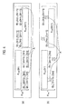
- the covariance matrix R I+N estimated (calculated) by the covariance matrix estimation unit 12 includes a first covariance matrix R I+N (2m) including a desired signal component in even-numbered resource elements in an SFBC pair and a second covariance matrix R I+N (2m+1) including a desired signal component in odd-numbered resource elements in the SFBC pair as illustrated in Fig. 2(a) .
- the covariance matrix averaging unit 13 is configured to perform an averaging process on each of elements in the first covariance matrix R I+N (2m) and elements in the second covariance matrix R I+N (2m+1) by using Equation illustrated in Fig. 2(b) .
- R ⁇ I + N 2 ⁇ m , R ⁇ I + N ⁇ 2 ⁇ m + 1 is acquired.
- the covariance matrix generation unit 16 may be configured to perform a process (a predetermined process) of changing each of the elements in the first covariance matrix R I+N (2m) and the elements in the second covariance matrix R I+N (2m+1), which are included in the covariance matrix R I+N estimated (calculated) by the covariance matrix estimation unit 12, into elements of Equation 2 received from the covariance matrix averaging unit 13, R ⁇ I + N 2 ⁇ m , R ⁇ I + N ⁇ 2 ⁇ m + 1 as illustrated in Fig. 2(c) .
- the covariance matrix R I+N when channel variation is ignored, is theoretically expressed by Equation illustrated in Fig. 3 . Furthermore, as illustrated in Fig. 3 , elements A in the covariance matrix R I+N are known to be theoretically "0" when the channel variation is ignored.
- the 0-value insertion unit 15 is configured to instruct the covariance matrix generation unit 16 to insert "0" into the elements A, which are theoretically to "0", when the channel variation is ignored, in the covariance matrix R I+N estimated by the covariance matrix estimation unit 12 and illustrated in Fig. 4(a) .
- the covariance matrix generation unit 16 may also be configured to perform a process (a predetermined process) of inserting "0" into the elements A in the covariance matrix R I+N , which is estimated by the covariance matrix estimation unit 12 and is illustrated in Fig. 4(a) , in response to the instruction from the 0-value insertion unit 15, as illustrated in Fig. 4(b) .
- a process a predetermined process
- the predetermined process illustrated in Fig. 4(b) is performed, that is, "0" is inserted into the elements A to be theoretically to "0", so that it is possible to improve the accuracy of estimating the covariance matrix R I+N based on the data signal while reducing a calculation amount.
- elements B in the covariance matrix R I+N estimated by the covariance matrix estimation unit 12 are theoretically expressed by one parameter x when the channel variation is ignored.
- the parameter averaging unit 14 is configured to perform an averaging process among the aforementioned elements B by using Equation illustrated in Fig. 5(c) . As a result, x ⁇ is acquired.
- the covariance matrix generation unit 16 may also be configured to change each of the elements B, which are included in the covariance matrix R I+N estimated (calculated) by the covariance matrix estimation unit 12, on the basis of Equation 4 x ⁇ received from the parameter averaging unit 14, as illustrated in Fig. 5(d) .
- the covariance matrix generation unit 16 may also be configured to perform a process (a predetermined process) of inserting "0" into the elements B, which are included in the covariance matrix R I+N estimated (calculated) by the covariance matrix estimation unit 12, in response to the instruction from the 0-value insertion unit 15 as illustrated in Fig. 6(c) .
- the predetermined process illustrated in Fig. 6(c) is performed, that is, "0" is inserted into the elements B, so that it is possible to improve the accuracy of estimating the covariance matrix R I+N based on the data signal while reducing a calculation amount.
- the covariance matrix generation unit 16 may also be configured to perform two or more combinations of the process illustrated in Fig. 2(c) , the process illustrated in Fig. 4(b) , the process illustrated in Fig. 5(d) , and the process illustrated in Fig. 6(c) .
- the control signal demodulation unit 17 is configured to perform a demodulation process on a control signal received from the serving cell (cell 1).
- the IRC reception weight generation unit 18 is configured to generate an IRC reception weight W IRC on the basis of the channel matrix H received from the channel estimation unit 11, the control signal received from the control signal demodulation unit 15, and the covariance matrix R I+N (the covariance matrix R I+N subjected to the predetermined process) received from the covariance matrix generation unit 16.
- the IRC reception weight generation unit 18 is configured to substitute the channel matrix H received from the channel estimation unit 11 and the covariance matrix R I+N received from the covariance matrix generation unit 16 into Equation illustrated in Fig. 10(a) , so as to generate the IRC reception weight W IRC .
- the signal separation unit 19 is configured to perform a signal separation process on a received signal from the serving cell (cell 1) on the basis of the control signal received from the control signal demodulation unit 17 and the IRC reception weight W IRC received from the IRC reception weight generation unit 18.
- the demodulation unit 20 is configured to perform a demodulation process on a signal received from the signal separation unit 19 on the basis of the control signal received from the control signal demodulation unit 17 and the IRC reception weight W IRC received from the IRC reception weight generation unit 18 so as to output a data signal.
- the IRC receiver 10 it is possible to improve the accuracy of estimating the covariance matrix R I+N based on the data signal by using the process illustrated in Fig. 2(c) , the process illustrated in Fig. 4(b) , the process illustrated in Fig. 5(d) , the process illustrated in Fig. 6(c) , and the like.
- an IRC receiver 10 which receives a data signal and a control signal transmitted using an SFBC (Space Frequency Block Coding) scheme, includes: a covariance matrix estimation unit 12 that estimates a covariance matrix R I+N on the basis of the data signal; a covariance matrix averaging unit 13 and a covariance matrix generation unit 16 that perform a predetermined process on the estimated covariance matrix R I+N ; an IRC reception weight generation unit 18 that generates an IRC reception weight W IRC by using the covariance matrix R I+N subjected to the predetermined process and the control signal; and a signal separation unit 19 that separates the data signal from a received signal by using the generated IRC reception weight W IRC and the control signal, wherein the data signal is configured to be transmitted in an SFBC pair (Space Frequency Block Coding scheme unit) including two resource elements, the estimated covariance matrix R I+N is configured to include a first covariance matrix R I+N (2m) including
- an IRC receiver 10 which receives a data signal and a control signal transmitted using an SFBC scheme, includes: a covariance matrix estimation unit 12 that estimates a covariance matrix R I+N on the basis of the data signal; a 0-value insertion unit 15 and a covariance matrix generation unit 16 that perform a predetermined process on the estimated covariance matrix R I+N ; an IRC reception weight generation unit 18 that generates an IRC reception weight W IRC by using the covariance matrix R I+N subjected to the predetermined process and the control signal; and a signal separation unit 19 that separates the data signal from a received signal by using the generated IRC reception weight W IRC and the control signal, wherein the 0-value insertion unit 15 and the covariance matrix generation unit 16 are configured to perform, as the aforementioned predetermined process, a process of inserting "0" into elements A, which are theoretically to "0" when channel variation is ignored, in the estimated covariance matrix R I+N
- an IRC receiver 10 which receives a data signal and a control signal transmitted using an SFBC scheme, include: a covariance matrix estimation unit 12 that estimates a covariance matrix R I+N on the basis of the data signal; a parameter averaging unit 14 and a covariance matrix generation unit 16 that perform a predetermined process on the estimated covariance matrix R I+N ; an IRC reception weight generation unit 18 that generates an IRC reception weight W IRC by using the covariance matrix R I+N subjected to the predetermined process and the control signal; and a signal separation unit 19 that separates the data signal from a received signal by using the generated IRC reception weight W IRC and the control signal, wherein the parameter averaging unit 14 and the covariance matrix generation unit 16 are configured to perform, as the aforementioned predetermined process, an averaging process among elements B, which are theoretically expressed by one parameter x when channel variation is ignored, in the estimated covariance matrix R I+N .
- an IRC receiver 10 which receives a data signal and a control signal transmitted using an SFBC scheme, includes: a covariance matrix estimation unit 12 that estimates a covariance matrix R I+N on the basis of the data signal; a 0-value insertion unit 15 and a covariance matrix generation unit 16 that perform a predetermined process on the estimated covariance matrix R I+N ; an IRC reception weight generation unit 18 that generates an IRC reception weight W IRC by using the covariance matrix R I+N subjected to the predetermined process and the control signal; and a signal separation unit 19 that separates the data signal from a received signal by using the generated IRC reception weight W IRC and the control signal, wherein the 0-value insertion unit 15 and the covariance matrix generation unit 16 are configured to perform, as the aforementioned predetermined process, a process of inserting "0" into an element, which is theoretically expressed by one parameter x when channel variation is ignored, in the estimated covariance matrix R I+
- IRC receiver 10 may be implemented by hardware, may also be implemented by a software module executed by a processor, or may further be implemented by the combination of the both.
- the software module may be arranged in a storage medium of an arbitrary format such as a RAM (Random Access Memory), a flash memory, a ROM (Read Only Memory), an EPROM (Erasable Programmable ROM), an EEPROM (Electronically Erasable and Programmable ROM), a register, a hard disk, a removable disk, or a CD-ROM.
- a RAM Random Access Memory
- flash memory a ROM (Read Only Memory)
- EPROM Erasable Programmable ROM
- EEPROM Electrically Erasable and Programmable ROM
- the storage medium is connected to the processor so that the processor can write and read information into and from the storage medium.
- a storage medium may also be accumulated in the processor.
- Such a storage medium and processor may be arranged in an ASIC.
- the ASIC may be arranged in the IRC receiver 10.
- such a storage medium and processor may be arranged in the IRC receiver 10 as discrete components.
Landscapes
- Engineering & Computer Science (AREA)
- Computer Networks & Wireless Communication (AREA)
- Signal Processing (AREA)
- Power Engineering (AREA)
- Physics & Mathematics (AREA)
- Mathematical Physics (AREA)
- Radio Transmission System (AREA)
- Noise Elimination (AREA)
Applications Claiming Priority (2)
| Application Number | Priority Date | Filing Date | Title |
|---|---|---|---|
| JP2011242911A JP5184691B1 (ja) | 2011-11-04 | 2011-11-04 | 受信器 |
| PCT/JP2012/078470 WO2013065821A1 (ja) | 2011-11-04 | 2012-11-02 | 受信器 |
Publications (1)
| Publication Number | Publication Date |
|---|---|
| EP2775647A1 true EP2775647A1 (en) | 2014-09-10 |
Family
ID=48192158
Family Applications (1)
| Application Number | Title | Priority Date | Filing Date |
|---|---|---|---|
| EP12845614.2A Withdrawn EP2775647A1 (en) | 2011-11-04 | 2012-11-02 | Receiver |
Country Status (5)
| Country | Link |
|---|---|
| US (1) | US20140314189A1 (ja) |
| EP (1) | EP2775647A1 (ja) |
| JP (1) | JP5184691B1 (ja) |
| CN (1) | CN103891185A (ja) |
| WO (1) | WO2013065821A1 (ja) |
Families Citing this family (1)
| Publication number | Priority date | Publication date | Assignee | Title |
|---|---|---|---|---|
| KR20180075190A (ko) | 2016-12-26 | 2018-07-04 | 삼성전자주식회사 | 무선 통신 시스템에서 신호의 간섭을 제거하는 방법 및 장치 |
Family Cites Families (7)
| Publication number | Priority date | Publication date | Assignee | Title |
|---|---|---|---|---|
| US7813311B2 (en) * | 2002-02-05 | 2010-10-12 | Interdigital Technology Corporation | Method and apparatus for synchronizing base stations |
| GB2394389B (en) * | 2002-10-15 | 2005-05-18 | Toshiba Res Europ Ltd | Equalisation apparatus and methods |
| ATE497287T1 (de) * | 2007-08-30 | 2011-02-15 | Ericsson Telefon Ab L M | Schätzung eines signal-zu-interferenz- verhältnisses bei einem empfänger eines drahtlosen kommunikationssystems |
| US7957485B2 (en) * | 2008-02-25 | 2011-06-07 | Telefonaktiebolaget Lm Ericsson (Publ) | Reduced complexity parametric covariance estimation for precoded MIMO transmissions |
| US20100232535A1 (en) * | 2009-03-04 | 2010-09-16 | Nec Laboratories America, Inc. | Apparatus and Method for Multilayer Space-Time-Frequency Precoding for a MIMO-OFDM Wireless Transmission System |
| US8488724B2 (en) * | 2009-05-14 | 2013-07-16 | Silvus Technologies, Inc. | Wideband interference mitigation for devices with multiple receivers |
| US8798119B2 (en) * | 2012-05-10 | 2014-08-05 | Telefonaktiebolaget L M Ericsson (Publ) | Symbol-level code-specific joint detection for CDMA receivers |
-
2011
- 2011-11-04 JP JP2011242911A patent/JP5184691B1/ja not_active Expired - Fee Related
-
2012
- 2012-11-02 WO PCT/JP2012/078470 patent/WO2013065821A1/ja active Application Filing
- 2012-11-02 US US14/354,009 patent/US20140314189A1/en not_active Abandoned
- 2012-11-02 CN CN201280052946.1A patent/CN103891185A/zh active Pending
- 2012-11-02 EP EP12845614.2A patent/EP2775647A1/en not_active Withdrawn
Non-Patent Citations (1)
| Title |
|---|
| See references of WO2013065821A1 * |
Also Published As
| Publication number | Publication date |
|---|---|
| JP5184691B1 (ja) | 2013-04-17 |
| JP2013098942A (ja) | 2013-05-20 |
| WO2013065821A1 (ja) | 2013-05-10 |
| US20140314189A1 (en) | 2014-10-23 |
| CN103891185A (zh) | 2014-06-25 |
Similar Documents
| Publication | Publication Date | Title |
|---|---|---|
| EP3573289B1 (en) | Combining channel quality measurements based on sounding reference signals and demodulation reference signals | |
| EP2996377B1 (en) | Method and device for submitting signal quality measurement information | |
| EP2218195B1 (en) | Method and apparatus for interference rejection combining and detection | |
| EP3621241B1 (en) | Uplink synchronization timing deviation determination method and device | |
| EP2777337B1 (en) | Multi-stage timing and frequency synchronization | |
| EP3051871B1 (en) | Base station, mobile station, wireless communication system, and wireless communication method | |
| EP3096466A1 (en) | Method and base station for enabling beamforming | |
| EP2645583A1 (en) | Mobile Device Searching Using Multiple Antennas | |
| EP3391601B1 (en) | Communication terminal and method for channel estimation | |
| EP2775771A1 (en) | Method and device for transmitting data on physical uplink control channel | |
| US20140086371A1 (en) | Interference cancellation apparatus and receiver | |
| EP2503817A1 (en) | Wireless base station | |
| EP3148279A1 (en) | Method and device for determining remote radio unit (rru) | |
| EP3282603A1 (en) | Interference cancellation method and base station apparatus therefor | |
| KR20150102974A (ko) | 유저장치, 기지국, 간섭 저감 방법, 및 간섭 저감 제어정보 통지방법 | |
| EP2775645A1 (en) | Receiver | |
| EP2680517B1 (en) | Channel spread estimation | |
| EP2381587B1 (en) | Method and device for determining antenna cooperation set, method and device for determining base station cooperation set | |
| EP3322144A1 (en) | Method and device for suppressing interference signal | |
| KR101552744B1 (ko) | 중계국에서 시간 계산을 송신하기 위한 시스템 및 방법 | |
| CN102013902A (zh) | 一种小区间干扰抑制方法和通信设备 | |
| EP2775647A1 (en) | Receiver | |
| WO2015170854A1 (ko) | Mimo 수신기에서 re 그룹을 형성하여 수신 신호를 처리하는 방법 | |
| EP2975896A1 (en) | Reception apparatus in wireless communication system and channel estimation control method | |
| US20140307838A1 (en) | Receiver |
Legal Events
| Date | Code | Title | Description |
|---|---|---|---|
| PUAI | Public reference made under article 153(3) epc to a published international application that has entered the european phase |
Free format text: ORIGINAL CODE: 0009012 |
|
| 17P | Request for examination filed |
Effective date: 20140515 |
|
| AK | Designated contracting states |
Kind code of ref document: A1 Designated state(s): AL AT BE BG CH CY CZ DE DK EE ES FI FR GB GR HR HU IE IS IT LI LT LU LV MC MK MT NL NO PL PT RO RS SE SI SK SM TR |
|
| DAX | Request for extension of the european patent (deleted) | ||
| STAA | Information on the status of an ep patent application or granted ep patent |
Free format text: STATUS: THE APPLICATION HAS BEEN WITHDRAWN |
|
| 18W | Application withdrawn |
Effective date: 20150204 |