EP2775289A1 - Fluorescent light phantom device and fluorescent light imaging method - Google Patents
Fluorescent light phantom device and fluorescent light imaging method Download PDFInfo
- Publication number
- EP2775289A1 EP2775289A1 EP12846772.7A EP12846772A EP2775289A1 EP 2775289 A1 EP2775289 A1 EP 2775289A1 EP 12846772 A EP12846772 A EP 12846772A EP 2775289 A1 EP2775289 A1 EP 2775289A1
- Authority
- EP
- European Patent Office
- Prior art keywords
- fluorescent light
- phantom
- fluorescent
- light
- phantoms
- Prior art date
- Legal status (The legal status is an assumption and is not a legal conclusion. Google has not performed a legal analysis and makes no representation as to the accuracy of the status listed.)
- Granted
Links
Images



Classifications
-
- G—PHYSICS
- G01—MEASURING; TESTING
- G01J—MEASUREMENT OF INTENSITY, VELOCITY, SPECTRAL CONTENT, POLARISATION, PHASE OR PULSE CHARACTERISTICS OF INFRARED, VISIBLE OR ULTRAVIOLET LIGHT; COLORIMETRY; RADIATION PYROMETRY
- G01J1/00—Photometry, e.g. photographic exposure meter
- G01J1/58—Photometry, e.g. photographic exposure meter using luminescence generated by light
-
- A—HUMAN NECESSITIES
- A61—MEDICAL OR VETERINARY SCIENCE; HYGIENE
- A61B—DIAGNOSIS; SURGERY; IDENTIFICATION
- A61B5/00—Measuring for diagnostic purposes; Identification of persons
- A61B5/0059—Measuring for diagnostic purposes; Identification of persons using light, e.g. diagnosis by transillumination, diascopy, fluorescence
- A61B5/0071—Measuring for diagnostic purposes; Identification of persons using light, e.g. diagnosis by transillumination, diascopy, fluorescence by measuring fluorescence emission
-
- A—HUMAN NECESSITIES
- A61—MEDICAL OR VETERINARY SCIENCE; HYGIENE
- A61B—DIAGNOSIS; SURGERY; IDENTIFICATION
- A61B5/00—Measuring for diagnostic purposes; Identification of persons
- A61B5/02—Detecting, measuring or recording for evaluating the cardiovascular system, e.g. pulse, heart rate, blood pressure or blood flow
- A61B5/026—Measuring blood flow
- A61B5/0261—Measuring blood flow using optical means, e.g. infrared light
-
- A—HUMAN NECESSITIES
- A61—MEDICAL OR VETERINARY SCIENCE; HYGIENE
- A61B—DIAGNOSIS; SURGERY; IDENTIFICATION
- A61B90/00—Instruments, implements or accessories specially adapted for surgery or diagnosis and not covered by any of the groups A61B1/00 - A61B50/00, e.g. for luxation treatment or for protecting wound edges
- A61B90/39—Markers, e.g. radio-opaque or breast lesions markers
-
- G—PHYSICS
- G01—MEASURING; TESTING
- G01N—INVESTIGATING OR ANALYSING MATERIALS BY DETERMINING THEIR CHEMICAL OR PHYSICAL PROPERTIES
- G01N21/00—Investigating or analysing materials by the use of optical means, i.e. using sub-millimetre waves, infrared, visible or ultraviolet light
- G01N21/17—Systems in which incident light is modified in accordance with the properties of the material investigated
- G01N21/25—Colour; Spectral properties, i.e. comparison of effect of material on the light at two or more different wavelengths or wavelength bands
- G01N21/27—Colour; Spectral properties, i.e. comparison of effect of material on the light at two or more different wavelengths or wavelength bands using photo-electric detection ; circuits for computing concentration
- G01N21/274—Calibration, base line adjustment, drift correction
- G01N21/278—Constitution of standards
-
- A—HUMAN NECESSITIES
- A61—MEDICAL OR VETERINARY SCIENCE; HYGIENE
- A61B—DIAGNOSIS; SURGERY; IDENTIFICATION
- A61B90/00—Instruments, implements or accessories specially adapted for surgery or diagnosis and not covered by any of the groups A61B1/00 - A61B50/00, e.g. for luxation treatment or for protecting wound edges
- A61B90/39—Markers, e.g. radio-opaque or breast lesions markers
- A61B2090/3937—Visible markers
- A61B2090/3941—Photoluminescent markers
-
- A—HUMAN NECESSITIES
- A61—MEDICAL OR VETERINARY SCIENCE; HYGIENE
- A61B—DIAGNOSIS; SURGERY; IDENTIFICATION
- A61B2560/00—Constructional details of operational features of apparatus; Accessories for medical measuring apparatus
- A61B2560/02—Operational features
- A61B2560/0223—Operational features of calibration, e.g. protocols for calibrating sensors
- A61B2560/0228—Operational features of calibration, e.g. protocols for calibrating sensors using calibration standards
- A61B2560/0233—Optical standards
-
- G—PHYSICS
- G01—MEASURING; TESTING
- G01N—INVESTIGATING OR ANALYSING MATERIALS BY DETERMINING THEIR CHEMICAL OR PHYSICAL PROPERTIES
- G01N21/00—Investigating or analysing materials by the use of optical means, i.e. using sub-millimetre waves, infrared, visible or ultraviolet light
- G01N21/62—Systems in which the material investigated is excited whereby it emits light or causes a change in wavelength of the incident light
- G01N21/63—Systems in which the material investigated is excited whereby it emits light or causes a change in wavelength of the incident light optically excited
- G01N21/64—Fluorescence; Phosphorescence
- G01N21/645—Specially adapted constructive features of fluorimeters
- G01N21/6456—Spatial resolved fluorescence measurements; Imaging
Definitions
- the invention relates to a fluorescent light phantom device and a fluorescent light imaging method.
- a method for determining the presence or absence of blood flow a method which is for determining the presence or absence of blood flow by injecting an indocyanine green (hereinafter referred to as "ICG") agent into a patient, then irradiating a target tissue with near-infrared light, and observing the tissue with a camera.
- ICG indocyanine green
- Calibration auxiliary means described in Patent Literature 1 is known as an example of calibration auxiliary means for normalizing measurement results in such a blood flow presence/absence determining method.
- the calibration auxiliary means described in Patent Literature 1 is prepared by dissolving an ICG coloring matter and albumin protein into water and impregnating a carrier sheet with the solution.
- Patent Literature 1 Japanese Patent Application Laid-Open No. 2005-300540
- the calibration auxiliary means described in Patent Literature 1 has the following problems. That is, it is difficult to adjust precisely the content concentration of a fluorescent coloring matter, since a carrier sheet such as paper or cloth is impregnated with solution including the fluorescent coloring matter in a manufacturing process step of the calibration auxiliary means. Moreover, there is concern over deterioration of fluorescence characteristics caused by denaturation of protein, since the fluorescent coloring matter is combined with the albumin protein in the calibration auxiliary means. Due to such reasons, it is difficult to evaluate quantitatively the content concentration of a fluorescent coloring matter in an object to be measured, using such calibration means.
- the present invention has been made for the purpose of solving the above problems, and an objective thereof is to provide a fluorescent light phantom device and a fluorescent light imaging method, which make it possible to evaluate quantitatively the concentration of a fluorescent coloring matter in an object to be measured.
- a fluorescent light phantom device comprises: a phantom support having a fluorescent light phantom container; and a fluorescent light phantom, which is constituted of a medium that reproduces at least one of light scattering and light absorption of an object to be measured and a fluorescent coloring matter contained in the medium at a predetermined concentration and is stored in the fluorescent light phantom container.
- a fluorescent light phantom device which is provided with a fluorescent light phantom having a content concentration of a fluorescent coloring matter that is a predetermined concentration, it becomes possible to compare the concentration of a fluorescent coloring matter in an object to be measured with the luminance of the fluorescent coloring matter in the fluorescent light phantom of the present invention and evaluate quantitatively the concentration by irradiating the object and the fluorescent light phantom with near-infrared light and comparing the luminance of fluorescent light from the object with the luminance of fluorescent light from the fluorescent light phantom for observation.
- the phantom support may have a plurality of fluorescent light phantom containers
- the fluorescent light phantom may be stored in each of a plurality of fluorescent light phantom containers
- the concentration of the fluorescent coloring matter contained in a fluorescent light phantom may be different in each fluorescent light phantom.
- the concentration of the fluorescent coloring matter is different in each of a plurality of fluorescent light phantoms, it becomes possible to evaluate more quantitatively the concentration of a fluorescent coloring matter in an object to be measured by comparing the luminance of fluorescent light from the object with the luminance of fluorescent light from a plurality of fluorescent light phantoms for observation.
- a fluorescent light phantom device comprises: a phantom support having a fluorescent light phantom container; and a fluorescent light phantom stored in the fluorescent light phantom container, and the fluorescent light phantom has: a surface layer dummy, which is constituted of a medium that reproduces at least one of light scattering and light absorption of an object to be measured and is disposed at a surface layer of the fluorescent light phantom container; a deep layer dummy, which is constituted of the medium and is disposed at a deep layer of the fluorescent light phantom container; and a tabular phantom, which is constituted of the medium and a fluorescent coloring matter contained in the medium and is disposed at the fluorescent light phantom container to be held between the surface layer dummy and the deep layer dummy.
- a tabular phantom is disposed between a surface layer dummy and a deep layer dummy, which are constituted of a medium that reproduces light scattering and light absorption of an object to be measured. Accordingly, even when scattering or light absorption occurs, it is possible to evaluate correctly the presence or absence of a fluorescent coloring matter in an object to be measured on the basis of a difference in the thickness of skin, fat or muscle of the object by irradiating the object and a fluorescent light phantom device of the present invention with near-infrared light and comparing the luminance of fluorescent light from the object with the luminance of fluorescent light from the fluorescent light phantom for observation.
- the phantom support may have a plurality of fluorescent light phantom containers
- the fluorescent light phantom may be stored in each of a plurality of fluorescent light phantom containers
- the tabular phantoms may have equivalent thicknesses in the respective fluorescent light phantoms, may contain the fluorescent coloring matter of equivalent concentrations, and may be disposed at different depths in the respective fluorescent light phantoms.
- tabular phantoms which have equivalent thicknesses and contain the fluorescent coloring matter of equivalent concentrations, are disposed at different depths in the respective fluorescent light phantoms.
- a tabular phantom is disposed between a surface layer dummy and a deep layer dummy, which are constituted of a medium that reproduces light scattering and light absorption of an object to be measured. Accordingly, even when scattering or light absorption occurs, it is possible to evaluate much more precisely the concentration of a fluorescent coloring matter in an object to be measured on the basis of a difference in the thickness of skin, fat or muscle of the object by irradiating the object and a fluorescent light phantom device of the present invention with near-infrared light and comparing the luminance of fluorescent light from the object with the luminance of fluorescent light from the fluorescent light phantom for observation.
- a fluorescent light phantom device is characterized in that the above fluorescent light phantom devices in which a plurality of fluorescent light phantom containers are arranged in a row are arranged in a plurality of rows so that fluorescent light phantoms are arranged in a matrix form, and the concentration of the fluorescent coloring matter contained in a tabular phantom is different for each row.
- the above fluorescent light phantom devices in which a plurality of fluorescent light phantom containers are arranged in a row are arranged in a plurality of rows so that fluorescent light phantoms are arranged in a matrix form, and the concentration of the fluorescent coloring matter contained in a tabular phantom is different for each row. Accordingly, it becomes possible to evaluate more precisely the concentration and the depth of a fluorescent coloring matter in an object to be measured by irradiating the object and a fluorescent light phantom device of the present invention with near-infrared light and comparing fluorescent light from the object with fluorescent light from the fluorescent light phantom device for observation.
- the phantom support and the fluorescent light phantom may be formed by epoxy resin.
- the phantom support, the standard phantom and the fluorescent light phantom are formed by epoxy resin and are solidified, there is no concern that a medium will evaporate, and reliability of the fluorescent coloring matter concentration is secured for a long time.
- the phantom support may further have a standard phantom container and may further have a standard phantom, which is constituted of a medium that reproduces at least one of light scattering and light absorption of an object to be measured and is stored in the standard phantom container.
- the medium may include: at least one kind of scattered particles selected from the group consisting of titanium dioxide particles, silica particles, polymer minute particles, alumina, quartz glass minute particles and lipid minute particles; and at least one light absorbing substance selected from the group consisting of a pigment and a dye.
- a fluorescent light phantom device is attached to an object to be measured before use and comprises a fluorescent light phantom, which is constituted of a medium that reproduces at least one of light scattering and light absorption of the object and a fluorescent coloring matter contained in the medium at a predetermined concentration.
- the fluorescent light phantom device can be bent along a curved surface.
- the surface of an object to be measured is a curved surface, it becomes possible to measure more precisely the luminance of fluorescent light from the object by bending the fluorescent light phantom device along the surface of the object.
- a plurality of fluorescent light phantoms may be provided, and the concentration of the fluorescent coloring matter contained in a fluorescent light phantom may be different in each fluorescent light phantom.
- concentration of the fluorescent coloring matter is different in each of a plurality of fluorescent light phantoms, it becomes possible to evaluate more quantitatively the concentration of a fluorescent coloring matter in an object to be measured by comparing the luminance of fluorescent light from the object with the luminance of fluorescent light from a plurality of fluorescent light phantoms for observation.
- the fluorescent light phantom may be formed by polyurethane resin or silicone resin.
- the fluorescent light phantom is formed in semi-solidified gel form, it becomes possible to bend the fluorescent light phantom device along the surface of an object to be measured and it also becomes possible to measure more precisely the luminance of fluorescent light from the object.
- the fluorescent coloring matter may be ICG.
- ICG which has optical characteristics such as an excitation wavelength within the range of 750 nm to 810 nm and a fluorescence wavelength with the center at 840 nm, is used as the fluorescent coloring matter.
- ICG which has optical characteristics such as an excitation wavelength within the range of 750 nm to 810 nm and a fluorescence wavelength with the center at 840 nm, is used as the fluorescent coloring matter.
- ICG which has optical characteristics such as an excitation wavelength within the range of 750 nm to 810 nm and a fluorescence wavelength with the center at 840 nm, is used as the fluorescent coloring matter.
- ICG which has optical characteristics such as an excitation wavelength within the range of 750 nm to 810 nm and a fluorescence wavelength with the center at 840 nm, is used as the fluorescent coloring matter.
- ICG which has optical characteristics such as an excitation wavelength within the range of 750 nm to 810 nm
- a fluorescent light imaging method comprises the following steps of: introducing a fluorescent coloring matter into a living body, disposing a fluorescent light phantom device of the present invention in the vicinity of the living body; irradiating the living body and the fluorescent light phantom device with excitation light; and detecting near-infrared fluorescent light from the fluorescent coloring matter introduced into the living body and the fluorescent coloring matter included in the fluorescent light phantom.
- a fluorescent light imaging method wherein a fluorescent light phantom device, which is provided with a fluorescent light phantom having a content concentration of a fluorescent coloring matter that is a predetermined concentration, is irradiated together with a living body which is an object to be measured, it is possible to evaluate quantitatively the concentration of a fluorescent coloring matter in the living body.
- a fluorescent light phantom device and a fluorescent light imaging method which make it possible to evaluate quantitatively the concentration of a fluorescent coloring matter in an object to be measured are obtained.
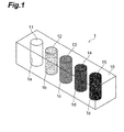
- Fig. 1 is a perspective view for illustrating the structure of a fluorescent light phantom device 1 according to a first embodiment.
- the fluorescent light phantom device 1 is composed of a phantom support 10, a standard phantom 11 and a plurality of (four in the present embodiment) fluorescent light phantoms 12, 13, 14 and 15.
- the phantom support 10 has a standard phantom container 1a to be used for storing the standard phantom 11, and a plurality of (four in the present embodiment) fluorescent light phantom containers 1b, 1c, 1d and 1e to be used for storing the fluorescent light phantoms 12, 13, 14 and 15. Moreover, the phantom support 10 is formed by epoxy resin.
- the standard phantom 11 is constituted of a medium which reproduces light scattering and light absorption of an object to be measured such as a living body, for example.
- a medium which constitutes the standard phantom 11 includes at least one kind of particles selected from the group consisting of titanium dioxide (TiO 2 ) particles, silica particles, polymer minute particles, alumina (Al 2 O 3 ), quartz glass minute particles and lipid minute particles as scattered particles for reproducing light scattering.
- TiO 2 titanium dioxide
- silica particles silica particles
- polymer minute particles polymer minute particles
- alumina (Al 2 O 3 ) alumina
- quartz glass minute particles quartz glass minute particles
- lipid minute particles as scattered particles for reproducing light scattering.
- lipid minute particles is milk, Intralipid (registered trademark) or the like.
- a medium which constitutes the standard phantom 11 includes at least one substance selected from the group consisting of a pigment and a dye as a light absorbing substance for reproducing light absorption.
- a medium which constitutes the standard phantom 11 is liquid obtained by mixing the above scattered particles and the above light absorbing substance with ethanol that functions as a solvent. The standard phantom 11 is stored in the standard phantom container 1a of the phantom support 10, and the standard phantom container 1a is sealed.
- the fluorescent light phantoms 12, 13, 14 and 15 are constituted of the above medium and a fluorescent coloring matter contained in the medium of a predetermined concentration.
- ICG is used as the fluorescent coloring matter.
- the concentration of ICG contained in the fluorescent light phantoms 12, 13, 14 and 15 is different for each of the fluorescent light phantoms 12, 13, 14 and 15.
- the fluorescent light phantoms 12 13, 14 and 15 are arranged in a row and are lined up in the order from one having a lower content concentration of ICG to one having a higher content concentration of ICG.
- the fluorescent light phantoms 12, 13, 14 and 15 are liquid and are stored in the fluorescent light phantom containers 1b, 1c, 1d and 1e of the phantom support 10, and the fluorescent light phantom containers 1b, 1c, 1d and 1e are sealed.
- ICG is introduced as a fluorescent coloring matter into a living body which is an object to be measured.
- the fluorescent light phantom device 1 is disposed in the vicinity of the living body.
- the living body and the fluorescent light phantom device 1 are then irradiated with excitation light using near-infrared light having an excitation wavelength within the range of 750 nm to 810 nm.
- near-infrared fluorescent light having a fluorescence wavelength with the center at a wavelength of 840 nm is generated from the ICG introduced into the living body.
- near-infrared fluorescent light having the same wavelength is also generated from the fluorescent light phantoms 12, 13, 14 and 15 of the fluorescent light phantom device 1.
- the intensity of near-infrared fluorescent light to be generated corresponds to the content concentration of ICG in the living body and the fluorescent light phantoms 12, 13, 14 and 15, and the intensity of near-infrared fluorescent light to be generated becomes higher as the content concentration of ICG becomes higher.
- the near-infrared fluorescent light is detected with a near-infrared camera, for example. It is possible to perform a fluorescent light imaging process by performing image processing for the detected near-infrared fluorescent light with a heretofore known method.
- Fig. 2 shows a photograph which is an example of the result of fluorescent light imaging with the method described above.
- Fig. 2 is a photograph of a living body and the fluorescent light phantom device 1 according to the first embodiment, which was taken with a near-infrared camera. Shining points are lined up in a row in the vertical direction at a slightly upper side than the central part of Fig. 2 . The brightness is different for each of the points, and a lower point is brighter. Since the brightness of a point corresponds to the content concentration of ICG in a fluorescent light phantom as described above, the fact that a lower point is brighter represents that the fact that a fluorescent light phantom corresponding to a lower point has a higher content concentration of ICG.
- a white shining part is spread around the points, which represent fluorescent light from the fluorescent light phantoms and are lined up vertically.
- the present embodiment which is provided with the fluorescent light phantoms 12, 13, 14 and 15 having a content concentration of the fluorescent coloring matter that is a predetermined concentration, it becomes possible to compare the concentration of a fluorescent coloring matter in an object to be measured with the luminance of a fluorescent coloring matter in the fluorescent light phantoms 12, 13, 14 and 15 and evaluate quantitatively the concentration by irradiating the object and the fluorescent light phantom device 1 of the present embodiment with near-infrared light and comparing the luminance of fluorescent light from the object with the luminance of fluorescent light from the fluorescent light phantoms 12, 13, 14 and 15 for observation.
- the fluorescent light phantom device 1 wherein the content concentration of the fluorescent coloring matter is different for each of fluorescent light phantoms 12, 13, 14 and 15, it becomes possible to evaluate more quantitatively the concentration of a fluorescent coloring matter in an object to be measured by comparing the luminance of fluorescent light from the object with the luminance of fluorescent light from a plurality of fluorescent light phantoms 12, 13, 14 and 15 for observation.
- the fluorescent light phantom device 1 since the fluorescent light phantom device 1 has the standard phantom 11, it becomes possible to evaluate more precisely the fluorescent light luminance without being affected by light scattering and light absorption, by comparing the fluorescent light luminance of the standard phantom 11, which is constituted of a medium that reproduces light scattering and light absorption of an object to be measured, with the fluorescent light luminance of the fluorescent light phantoms 12, 13, 14 and 15, which are constituted of the above medium and a fluorescent coloring matter contained in the medium.
- the medium which constitutes the standard phantom 11 and the fluorescent light phantoms 12, 13, 14 and 15 includes at least one kind of scattered particles selected from the group consisting of titanium dioxide particles, silica particles, polymer minute particles, alumina, quartz glass minute particles and lipid minute particles and at least one light absorbing substance selected from the group consisting of a pigment and a dye, light scattering and light absorption of an object to be measured are reproduced more accurately and the fluorescent light luminance is measured more accurately.
- the fluorescent light phantom device 1 provided with a plurality of fluorescent light phantoms 12, 13, 14 and 15 having respectively different content concentrations of the fluorescent coloring matter is irradiated together with a living body which is an object to be measured, it is possible to evaluate quantitatively the concentration of a fluorescent coloring matter in the living body.
- the fluorescent light phantom device 1 wherein ICG is used as the fluorescent coloring matter, it is possible in fluorescence observation for a living body as an object to be measured to observe a living body deep site while being hardly affected by light absorption by blood, which absorbs light having a wavelength shorter than 600 nm, or water, which absorbs light having a wavelength longer than 1000 nm, since ICG, which has optical characteristics such as an excitation wavelength within the range of 750 nm to 810 nm and a fluorescence wavelength with the center at 840 nm, is used as the fluorescent coloring matter.
- a solvent which constitutes the standard phantom and the fluorescent light phantoms in the present embodiment is not limited to ethanol, and methanol, dimethyl sulfoxide, water or the like can be used instead of ethanol.
- a medium which constitutes the standard phantom 11 and the fluorescent light phantoms 12, 13, 14 and 15 does not necessarily include both of light scattering particles and a light absorbing substance but needs only to include at least one thereof.
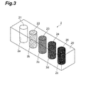
- Fig. 3 is a perspective view for illustrating the structure of a fluorescent light phantom device 2 according to the second embodiment.
- the fluorescent light phantom device 2 according to the second embodiment is different from the fluorescent light phantom device 1 according to the first embodiment in that a standard phantom 21 and fluorescent light phantoms 22, 23, 24 and 25 are formed by epoxy resin and are solidified. Accordingly, the difference from the first embodiment will be mainly explained.
- the fluorescent light phantom device 2 is composed of a phantom support 20, the standard phantom 21 and the fluorescent light phantoms 22, 23, 24 and 25.
- the phantom support 20 is provided with a standard phantom container 2a to be used for storing the standard phantom 21, and fluorescent light phantom containers 2b, 2c, 2d and 2e to be used for storing the fluorescent light phantoms 22, 23, 24 and 25.
- the standard phantom 21 is constituted of a medium which reproduces light scattering and light absorption as with the standard phantom 11 of the first embodiment. Substances similar to those of the first embodiment can be used as the light scattering particles and the light absorbing substance included in the medium.
- the medium is obtained by mixing light scattering particles and a light absorbing substance with ethanol and further mixing the liquid with epoxy resin so as to solidify the liquid.
- the fluorescent light phantoms 22, 23, 24 and 25 are constituted of the above medium and ICG contained in the medium of a predetermined concentration. More specifically, the medium is formed by mixing light scattering particles and a light absorbing substance with ethanol, further dissolving ICG of a predetermined concentration, and mixing epoxy resin so as to solidify the liquid.
- the concentration of ICG contained in the fluorescent light phantoms 22 23, 24 and 25 is different for each of the fluorescent light phantoms 22, 23, 24 and 25.
- the fluorescent light phantoms 22, 23, 24 and 25 are arranged in a row and are lined up in the order from one having a lower content concentration of ICG to one having a higher content concentration of ICG.
- the present embodiment an effect similar to that of the first embodiment can be obtained. Furthermore, with the fluorescent light phantom device 2 wherein the standard phantom 21 and the fluorescent light phantoms 22, 23, 24 and 25 are formed by epoxy resin, the standard phantom 21 and the fluorescent light phantoms 22, 23, 24 and 25 are solidified, there is no concern that the medium will evaporate, and reliability of the fluorescent coloring matter concentration is secured for a long time.
- Fig. 4 is a plan view for illustrating the structure of a fluorescent light phantom device 3 according to the third embodiment.
- the fluorescent light phantom device 3 according to the third embodiment is composed of a standard phantom 31 and fluorescent light phantoms 32 and 33. Moreover, the fluorescent light phantom device 3 is attached to an object to be measured before use.
- the standard phantom 31 is constituted of a medium which reproduces light scattering and light absorption of an object to be measured. Specifically, the medium is obtained by mixing ethanol, which includes light scattering particles and a light absorbing substance similar to those of the first embodiment mixed therein, with polyurethane resin. Since polyurethane resin is mixed with the medium, the standard phantom 31 is semi-solidified and formed in gel form.
- the fluorescent light phantoms 32 and 33 are constituted of the above medium and ICG contained in the medium of a predetermined concentration. Accordingly, the fluorescent light phantoms 32 and 33 are also semi-solidified and are formed in gel form as with the standard phantom 31.
- the fluorescent light phantom device 3 having the above structure is in a semi-solidified form which can be bent along a curved surface.
- Fig. 5 is a schematic diagram for illustrating the usage of the fluorescent light phantom device 3 according to the third embodiment.
- the surface of a living body B which is an object to be measured, forms a convex curved surface.
- the fluorescent light phantom device 3 is bent along the surface of the living body B and is placed on the living body B.
- a near-infrared camera P is then brought close to from a direction perpendicular to the surface of the fluorescent light phantom device 3, and a photograph of the fluorescent light phantom device 3 and the living body is taken with the near-infrared camera P.
- the fluorescent light phantom device 3 having the above structure, effects similar to those of a case where the fluorescent light phantom device 1 according to the first embodiment is used are obtained. Moreover, in the fluorescent light phantom device 3 wherein the standard phantom 31 and the fluorescent light phantoms 32, 33, 34 and 35 are formed by polyurethane resin, it is possible to bend the fluorescent light phantom device along a curved surface. Therefore, when the surface of an object to be measured is a curved surface, it becomes possible to measure more precisely the luminance of fluorescent light from the object by bending the fluorescent light phantom device along the surface of the object.
- silicone resin for example, may be used instead of polyurethane resin as resin to be used for semi-solidifying the fluorescent light phantom device 3 and forming the same in gel form in the present embodiment.
- Fig. 6 is a perspective view for illustrating the structure of a fluorescent light phantom device 4 according to the fourth embodiment.
- the fluorescent light phantom device 4 according to the fourth embodiment is composed of a phantom support 40, a standard phantom 41 and a plurality of (four in the present embodiment) fluorescent light phantoms 42, 43, 44 and 45.
- the phantom support 40 is provided with a standard phantom container 4a to be used for storing the standard phantom 41, and fluorescent light phantom containers 4b, 4c, 4d and 4e to be used for storing the fluorescent light phantoms 42, 43, 44 and 45.
- the standard phantom 41 is constituted of a medium, which is obtained by mixing epoxy resin with ethanol including light scattering particles and a light absorbing substance mixed therein, and is formed in a solidified form as with the standard phantom 21 of the second embodiment.
- the fluorescent light phantom 42 has a surface layer dummy 42A, a tabular phantom 42B and a deep layer dummy 42C.
- the surface layer dummy 42A is constituted of a medium which reproduces light scattering and light absorption of an object to be measured.
- the surface layer dummy 42A is disposed at a surface layer of a fluorescent light phantom container 4b which is provided at the phantom support 40.
- the deep layer dummy 42C is constituted of the above medium and is disposed at a deep layer of the fluorescent light phantom container 4b.
- the tabular phantom 42B is constituted of the above medium and ICG contained in the medium as the fluorescent coloring matter.
- the tabular phantom 42B is disposed at the fluorescent light phantom container 4b so as to be held between the surface layer dummy 42A and the deep layer dummy 42C.
- the fluorescent light phantom 43 has a surface layer dummy 43A, a tabular phantom 43B and a deep layer dummy 43C, and the tabular phantom 43B is disposed at the fluorescent light phantom container 4c so as to be held between the surface layer dummy 43A and the deep layer dummy 43C.
- the fluorescent light phantom 44 has a surface layer dummy 44A, a tabular phantom 44B and a deep layer dummy 44C, and the tabular phantom 44B is disposed at the fluorescent light phantom container 4d so as to be held between the surface layer dummy 44A and the deep layer dummy 44C.
- the fluorescent light phantom 45 is composed of a surface layer dummy 45A and a tabular phantom 45B.
- the tabular phantom 45B is disposed at the deepest part of the fluorescent light phantom container 4e, and a deep layer dummy is not provided.
- the tabular phantoms 42B, 43B, 44B and 45B have equivalent thickness in the respective fluorescent light phantoms 42, 43, 44 and 45 and contain ICG of equivalent concentrations. Moreover, the tabular phantoms 42B, 43B, 44B and 45B are disposed at a different depth in each fluorescent light phantom. In the present embodiment, the fluorescent light phantoms 42, 43, 44 and 45 are arranged in a row and are constructed in such a manner that the depth where the tabular phantoms 42B, 43B, 44B and 45B are disposed becomes deeper in order.
- the tabular phantom 42B is disposed between the surface layer dummy 42A and the deep layer dummy 42C, which are constituted of a medium that reproduces light scattering and light absorption of an object to be measured. Accordingly, even when scattering or light absorption occurs, it is possible to evaluate correctly the presence or absence of a fluorescent coloring matter in an object to be measured on the basis of a difference in the thickness of skin, fat or muscle of the object by irradiating the object and the fluorescent light phantom device 4 of the present embodiment with near-infrared light and comparing the luminance of fluorescent light from the object with the luminance of fluorescent light from the fluorescent light phantom for observation.
- the tabular phantoms 42B, 43B, 44B and 45B which have equivalent thicknesses and contain the fluorescent coloring matter of equivalent concentrations are disposed at a different depth in each of the fluorescent light phantoms 42, 43, 44 and 45 in such a case.
- the tabular phantom 42B is disposed between the surface layer dummy 42A and the deep layer dummy 42C, which are constituted of a medium that reproduces light scattering and light absorption of an object to be measured.
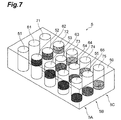
- Fig. 7 is a perspective view for illustrating the structure of a fluorescent light phantom device 4 according to the fifth embodiment.
- the fluorescent light phantom device 5 according to the fifth embodiment is composed of a phantom support 50, standard phantoms 51, 61 and 71, and fluorescent light phantoms 52, 53, 54, 55, 62, 63, 64, 65, 72, 73, 74 and 75.
- the standard phantoms 51, 61 and 71 are constituted of a medium, which is obtained by mixing epoxy resin with ethanol including light scattering particles and a light absorbing substance mixed therein, and is formed in a solidified form as with the standard phantom 41 according to the fourth embodiment.
- the fluorescent light phantoms 52, 53, 54, 55, 62, 63, 64, 65, 72, 73, 74 and 75 respectively have a tabular phantom as with the fluorescent light phantoms 42, 43, 44 and 45 according to the fourth embodiment.
- the standard phantom 51 and the fluorescent light phantoms 52, 53, 54 and 55 are arranged in a row
- the standard phantom 61 and the fluorescent light phantoms 62, 63, 64 and 65 are arranged in a row
- the standard phantom 71 and the fluorescent light phantoms 72, 73, 74 and 75 are arranged in a row.
- the tabular phantoms provided at the fluorescent light phantoms 52, 53, 54 and 55 have equivalent thicknesses, contain ICG of equivalent concentrations, and are provided at different depths.
- the tabular phantoms provided at the fluorescent light phantoms 62, 63, 64 and 65 have equivalent thicknesses, contain ICG of equivalent concentrations, and are provided at different depths.
- the tabular phantoms provided at the fluorescent light phantoms 72, 73, 74 and 75 have equivalent thicknesses, contain ICG of equivalent concentrations, and are provided at different depths.
- the concentration of ICG contained in the fluorescent light phantoms 52, 62 and 72 are different from each other.
- the phantom support 50, the standard phantom 51 and the fluorescent light phantoms 52, 53, 54 and 55 compose a phantom device 5A of the fourth embodiment.
- the phantom support 50, the standard phantom 61 and the fluorescent light phantoms 62, 63, 64 and 65 compose a phantom device 5B of the fourth embodiment
- the phantom support 50, the standard phantom 71 and the fluorescent light phantoms 72, 73, 74 and 75 compose a phantom device 5C of the fourth embodiment.
- the fluorescent light phantom device 5 of the present embodiment can be considered as an assembly wherein the three fluorescent light phantoms devices 5A to 5C are arranged in a plurality of rows (arranged in three rows in the present embodiment).
- the fluorescent light phantoms 52, 53, 54, 55, 62, 63, 64, 65, 72, 73, 74 and 75 are arranged in a matrix form.
- the concentration of ICG contained in each fluorescent light phantom is different for each row.
- the fluorescent light phantom device 5 is constructed in such a manner that fluorescent light phantom devices in which a plurality of fluorescent light phantom containers are arranged in a row are arranged in a plurality of rows so that fluorescent light phantoms are arranged in a matrix form, and the concentration of the fluorescent coloring matter contained in the tabular phantoms is different for each row. Accordingly, it becomes possible to evaluate more precisely the concentration and the depth of the fluorescent coloring matter in an object to be measured by irradiating the object and the fluorescent light phantom device 5 of the present embodiment with near-infrared light and comparing fluorescent light from the object with fluorescent light from the fluorescent light phantom device 5 for observation.
- the fluorescent light phantom devices 1 to 5 and a fluorescent light imaging method which make it possible to evaluate quantitatively the concentration of a fluorescent coloring matter in an object to be measured, are provided.
Landscapes
- Health & Medical Sciences (AREA)
- Life Sciences & Earth Sciences (AREA)
- Physics & Mathematics (AREA)
- Pathology (AREA)
- General Health & Medical Sciences (AREA)
- Surgery (AREA)
- Engineering & Computer Science (AREA)
- Animal Behavior & Ethology (AREA)
- Veterinary Medicine (AREA)
- Biomedical Technology (AREA)
- Heart & Thoracic Surgery (AREA)
- Medical Informatics (AREA)
- Molecular Biology (AREA)
- Public Health (AREA)
- Spectroscopy & Molecular Physics (AREA)
- General Physics & Mathematics (AREA)
- Biophysics (AREA)
- Nuclear Medicine, Radiotherapy & Molecular Imaging (AREA)
- Hematology (AREA)
- Oral & Maxillofacial Surgery (AREA)
- Cardiology (AREA)
- Physiology (AREA)
- Mathematical Physics (AREA)
- Theoretical Computer Science (AREA)
- Chemical & Material Sciences (AREA)
- Analytical Chemistry (AREA)
- Biochemistry (AREA)
- Immunology (AREA)
- Investigating, Analyzing Materials By Fluorescence Or Luminescence (AREA)
- Measuring Pulse, Heart Rate, Blood Pressure Or Blood Flow (AREA)
Abstract
Description
- The invention relates to a fluorescent light phantom device and a fluorescent light imaging method.
- In skin flap surgery in the field of plastic surgery, it is known that the presence or absence of blood flow in a transplanted living body tissue significantly affects recuperation after surgery. As a method for determining the presence or absence of blood flow, a method is known which is for determining the presence or absence of blood flow by injecting an indocyanine green (hereinafter referred to as "ICG") agent into a patient, then irradiating a target tissue with near-infrared light, and observing the tissue with a camera. Calibration auxiliary means described in
Patent Literature 1 is known as an example of calibration auxiliary means for normalizing measurement results in such a blood flow presence/absence determining method. The calibration auxiliary means described inPatent Literature 1 is prepared by dissolving an ICG coloring matter and albumin protein into water and impregnating a carrier sheet with the solution. - Patent Literature 1: Japanese Patent Application Laid-Open No.
2005-300540 - However, the calibration auxiliary means described in
Patent Literature 1 has the following problems. That is, it is difficult to adjust precisely the content concentration of a fluorescent coloring matter, since a carrier sheet such as paper or cloth is impregnated with solution including the fluorescent coloring matter in a manufacturing process step of the calibration auxiliary means. Moreover, there is concern over deterioration of fluorescence characteristics caused by denaturation of protein, since the fluorescent coloring matter is combined with the albumin protein in the calibration auxiliary means. Due to such reasons, it is difficult to evaluate quantitatively the content concentration of a fluorescent coloring matter in an object to be measured, using such calibration means. - The present invention has been made for the purpose of solving the above problems, and an objective thereof is to provide a fluorescent light phantom device and a fluorescent light imaging method, which make it possible to evaluate quantitatively the concentration of a fluorescent coloring matter in an object to be measured.
- In order to achieve such an objective, a fluorescent light phantom device according to an aspect of the present invention comprises: a phantom support having a fluorescent light phantom container; and a fluorescent light phantom, which is constituted of a medium that reproduces at least one of light scattering and light absorption of an object to be measured and a fluorescent coloring matter contained in the medium at a predetermined concentration and is stored in the fluorescent light phantom container.
- In a fluorescent light phantom device according to an aspect of the present invention which is provided with a fluorescent light phantom having a content concentration of a fluorescent coloring matter that is a predetermined concentration, it becomes possible to compare the concentration of a fluorescent coloring matter in an object to be measured with the luminance of the fluorescent coloring matter in the fluorescent light phantom of the present invention and evaluate quantitatively the concentration by irradiating the object and the fluorescent light phantom with near-infrared light and comparing the luminance of fluorescent light from the object with the luminance of fluorescent light from the fluorescent light phantom for observation.
- Moreover, in a fluorescent light phantom device according to an aspect of the present invention, the phantom support may have a plurality of fluorescent light phantom containers, the fluorescent light phantom may be stored in each of a plurality of fluorescent light phantom containers, and the concentration of the fluorescent coloring matter contained in a fluorescent light phantom may be different in each fluorescent light phantom. In such a case wherein the concentration of the fluorescent coloring matter is different in each of a plurality of fluorescent light phantoms, it becomes possible to evaluate more quantitatively the concentration of a fluorescent coloring matter in an object to be measured by comparing the luminance of fluorescent light from the object with the luminance of fluorescent light from a plurality of fluorescent light phantoms for observation.
- Moreover, a fluorescent light phantom device according to an aspect of the present invention comprises: a phantom support having a fluorescent light phantom container; and a fluorescent light phantom stored in the fluorescent light phantom container, and the fluorescent light phantom has: a surface layer dummy, which is constituted of a medium that reproduces at least one of light scattering and light absorption of an object to be measured and is disposed at a surface layer of the fluorescent light phantom container; a deep layer dummy, which is constituted of the medium and is disposed at a deep layer of the fluorescent light phantom container; and a tabular phantom, which is constituted of the medium and a fluorescent coloring matter contained in the medium and is disposed at the fluorescent light phantom container to be held between the surface layer dummy and the deep layer dummy.
- In a fluorescent light phantom device according to an aspect of the present invention, a tabular phantom is disposed between a surface layer dummy and a deep layer dummy, which are constituted of a medium that reproduces light scattering and light absorption of an object to be measured. Accordingly, even when scattering or light absorption occurs, it is possible to evaluate correctly the presence or absence of a fluorescent coloring matter in an object to be measured on the basis of a difference in the thickness of skin, fat or muscle of the object by irradiating the object and a fluorescent light phantom device of the present invention with near-infrared light and comparing the luminance of fluorescent light from the object with the luminance of fluorescent light from the fluorescent light phantom for observation.
- Moreover, in a fluorescent light phantom device according to an aspect of the present invention, the phantom support may have a plurality of fluorescent light phantom containers, the fluorescent light phantom may be stored in each of a plurality of fluorescent light phantom containers, and the tabular phantoms may have equivalent thicknesses in the respective fluorescent light phantoms, may contain the fluorescent coloring matter of equivalent concentrations, and may be disposed at different depths in the respective fluorescent light phantoms. In such a case, tabular phantoms, which have equivalent thicknesses and contain the fluorescent coloring matter of equivalent concentrations, are disposed at different depths in the respective fluorescent light phantoms. Moreover, a tabular phantom is disposed between a surface layer dummy and a deep layer dummy, which are constituted of a medium that reproduces light scattering and light absorption of an object to be measured. Accordingly, even when scattering or light absorption occurs, it is possible to evaluate much more precisely the concentration of a fluorescent coloring matter in an object to be measured on the basis of a difference in the thickness of skin, fat or muscle of the object by irradiating the object and a fluorescent light phantom device of the present invention with near-infrared light and comparing the luminance of fluorescent light from the object with the luminance of fluorescent light from the fluorescent light phantom for observation.
- Moreover, a fluorescent light phantom device according to an aspect of the present invention is characterized in that the above fluorescent light phantom devices in which a plurality of fluorescent light phantom containers are arranged in a row are arranged in a plurality of rows so that fluorescent light phantoms are arranged in a matrix form, and the concentration of the fluorescent coloring matter contained in a tabular phantom is different for each row.
- In a fluorescent light phantom device according to an aspect of the present invention, the above fluorescent light phantom devices in which a plurality of fluorescent light phantom containers are arranged in a row are arranged in a plurality of rows so that fluorescent light phantoms are arranged in a matrix form, and the concentration of the fluorescent coloring matter contained in a tabular phantom is different for each row. Accordingly, it becomes possible to evaluate more precisely the concentration and the depth of a fluorescent coloring matter in an object to be measured by irradiating the object and a fluorescent light phantom device of the present invention with near-infrared light and comparing fluorescent light from the object with fluorescent light from the fluorescent light phantom device for observation.
- Moreover, in a fluorescent light phantom device according to an aspect of the present invention, the phantom support and the fluorescent light phantom may be formed by epoxy resin. In such a case wherein the phantom support, the standard phantom and the fluorescent light phantom are formed by epoxy resin and are solidified, there is no concern that a medium will evaporate, and reliability of the fluorescent coloring matter concentration is secured for a long time.
- Moreover, in a fluorescent light phantom device according to an aspect of the present invention, the phantom support may further have a standard phantom container and may further have a standard phantom, which is constituted of a medium that reproduces at least one of light scattering and light absorption of an object to be measured and is stored in the standard phantom container. In such a case, it becomes possible to evaluate more precisely the fluorescent light luminance without being affected by light scattering and light absorption by comparing the fluorescent light luminance of a standard phantom, which is constituted of a medium that reproduces light scattering and light absorption of an object to be measured with the fluorescent light luminance of a fluorescent light phantom, which is constituted of the above medium and a fluorescent coloring matter contained in the medium.
- Moreover, in a fluorescent light phantom device according to an aspect of the present invention, the medium may include: at least one kind of scattered particles selected from the group consisting of titanium dioxide particles, silica particles, polymer minute particles, alumina, quartz glass minute particles and lipid minute particles; and at least one light absorbing substance selected from the group consisting of a pigment and a dye. Thus, light scattering and light absorption of an object to be measured are reproduced more accurately, and the fluorescent light luminance is measured more accurately.
- Moreover, a fluorescent light phantom device according to an aspect of the present invention is attached to an object to be measured before use and comprises a fluorescent light phantom, which is constituted of a medium that reproduces at least one of light scattering and light absorption of the object and a fluorescent coloring matter contained in the medium at a predetermined concentration. In such a case wherein the fluorescent light phantom device is attached to an object to be measured before use, the fluorescent light phantom device can be bent along a curved surface. When the surface of an object to be measured is a curved surface, it becomes possible to measure more precisely the luminance of fluorescent light from the object by bending the fluorescent light phantom device along the surface of the object.
- Moreover, in a fluorescent light phantom device according to an aspect of the present invention, a plurality of fluorescent light phantoms may be provided, and the concentration of the fluorescent coloring matter contained in a fluorescent light phantom may be different in each fluorescent light phantom. In such a case wherein the concentration of the fluorescent coloring matter is different in each of a plurality of fluorescent light phantoms, it becomes possible to evaluate more quantitatively the concentration of a fluorescent coloring matter in an object to be measured by comparing the luminance of fluorescent light from the object with the luminance of fluorescent light from a plurality of fluorescent light phantoms for observation.
- Moreover, in a fluorescent light phantom device according to an aspect of the present invention, the fluorescent light phantom may be formed by polyurethane resin or silicone resin. In such a case wherein the fluorescent light phantom is formed in semi-solidified gel form, it becomes possible to bend the fluorescent light phantom device along the surface of an object to be measured and it also becomes possible to measure more precisely the luminance of fluorescent light from the object.
- Moreover, in a fluorescent light phantom device according to an aspect of the present invention, the fluorescent coloring matter may be ICG. Thus, it is possible in fluorescence observation for a living body as an object to be measured to observe a living body deep site while being hardly affected by light absorption by blood, which absorbs light having a wavelength shorter than 600 nm, or water, which absorbs light having a wavelength longer than 1000 nm, since ICG, which has optical characteristics such as an excitation wavelength within the range of 750 nm to 810 nm and a fluorescence wavelength with the center at 840 nm, is used as the fluorescent coloring matter. Moreover, it is possible to inlet ICG, which is harmless to a living body, into a living body and perform fluorescence observation using a fluorescent light phantom device according to an aspect of the present invention.
- Moreover, a fluorescent light imaging method according to an aspect of the present invention comprises the following steps of: introducing a fluorescent coloring matter into a living body, disposing a fluorescent light phantom device of the present invention in the vicinity of the living body; irradiating the living body and the fluorescent light phantom device with excitation light; and detecting near-infrared fluorescent light from the fluorescent coloring matter introduced into the living body and the fluorescent coloring matter included in the fluorescent light phantom.
- With a fluorescent light imaging method according to an aspect of the present invention wherein a fluorescent light phantom device, which is provided with a fluorescent light phantom having a content concentration of a fluorescent coloring matter that is a predetermined concentration, is irradiated together with a living body which is an object to be measured, it is possible to evaluate quantitatively the concentration of a fluorescent coloring matter in the living body.
- With the present invention, a fluorescent light phantom device and a fluorescent light imaging method which make it possible to evaluate quantitatively the concentration of a fluorescent coloring matter in an object to be measured are obtained.
-
-
Fig. 1 is a perspective view for illustrating the structure of a fluorescent light phantom device according to a first embodiment. -
Fig. 2 is a photograph of a living body and a fluorescent light phantom device according to the first embodiment, which is taken with a near-infrared camera. -
Fig. 3 is a perspective view for illustrating the structure of a fluorescent light phantom device according to a second embodiment. -
Fig. 4 is a plan view for illustrating the structure of a fluorescent light phantom device according to a third embodiment. -
Fig. 5 is a schematic diagram for illustrating the usage of a fluorescent light phantom device according to the third embodiment. -
Fig. 6 is a perspective view for illustrating the structure of a fluorescent light phantom device according to a fourth embodiment. -
Fig. 7 is a perspective view for illustrating the structure of a fluorescent light phantom device according to a fifth embodiment. - The following description will explain preferred embodiments of a fluorescent light phantom device according to the present invention with reference to the drawings. It is to be noted that identical elements in the respective figures are denoted by identical symbols and repetition in a description will be omitted.
-
Fig. 1 is a perspective view for illustrating the structure of a fluorescentlight phantom device 1 according to a first embodiment. As illustrated in the figure, the fluorescentlight phantom device 1 is composed of aphantom support 10, astandard phantom 11 and a plurality of (four in the present embodiment)fluorescent light phantoms - The
phantom support 10 has astandard phantom container 1a to be used for storing thestandard phantom 11, and a plurality of (four in the present embodiment) fluorescentlight phantom containers fluorescent light phantoms phantom support 10 is formed by epoxy resin. - The
standard phantom 11 is constituted of a medium which reproduces light scattering and light absorption of an object to be measured such as a living body, for example. Specifically, a medium which constitutes thestandard phantom 11 includes at least one kind of particles selected from the group consisting of titanium dioxide (TiO2) particles, silica particles, polymer minute particles, alumina (Al2O3), quartz glass minute particles and lipid minute particles as scattered particles for reproducing light scattering. It is to be noted that a specific example of lipid minute particles is milk, Intralipid (registered trademark) or the like. Moreover, a medium which constitutes thestandard phantom 11 includes at least one substance selected from the group consisting of a pigment and a dye as a light absorbing substance for reproducing light absorption. In the present embodiment, a medium which constitutes thestandard phantom 11 is liquid obtained by mixing the above scattered particles and the above light absorbing substance with ethanol that functions as a solvent. Thestandard phantom 11 is stored in thestandard phantom container 1a of thephantom support 10, and thestandard phantom container 1a is sealed. - The
fluorescent light phantoms fluorescent light phantoms fluorescent light phantoms fluorescent light phantoms 12 13, 14 and 15 are arranged in a row and are lined up in the order from one having a lower content concentration of ICG to one having a higher content concentration of ICG. In the present embodiment, thefluorescent light phantoms light phantom containers phantom support 10, and the fluorescentlight phantom containers - Next, a fluorescent light imaging method which uses the fluorescent light
phantom device 1 of the present embodiment will be explained. First, ICG is introduced as a fluorescent coloring matter into a living body which is an object to be measured. Next, the fluorescent lightphantom device 1 is disposed in the vicinity of the living body. The living body and the fluorescent lightphantom device 1 are then irradiated with excitation light using near-infrared light having an excitation wavelength within the range of 750 nm to 810 nm. Here, near-infrared fluorescent light having a fluorescence wavelength with the center at a wavelength of 840 nm is generated from the ICG introduced into the living body. Moreover, near-infrared fluorescent light having the same wavelength is also generated from thefluorescent light phantoms phantom device 1. Here, the intensity of near-infrared fluorescent light to be generated corresponds to the content concentration of ICG in the living body and thefluorescent light phantoms -
Fig. 2 shows a photograph which is an example of the result of fluorescent light imaging with the method described above.Fig. 2 is a photograph of a living body and the fluorescent lightphantom device 1 according to the first embodiment, which was taken with a near-infrared camera. Shining points are lined up in a row in the vertical direction at a slightly upper side than the central part ofFig. 2 . The brightness is different for each of the points, and a lower point is brighter. Since the brightness of a point corresponds to the content concentration of ICG in a fluorescent light phantom as described above, the fact that a lower point is brighter represents that the fact that a fluorescent light phantom corresponding to a lower point has a higher content concentration of ICG. Moreover, it becomes possible to correlate the content concentration of ICG to the brightness of a point on the basis of the brightness of the points lined up in a row, since the content concentration of ICG included in the fluorescent light phantom is known. That is, parts which shine at the same degree of brightness have the same level of content concentration of ICG. - Moreover, in
Fig. 2 , a white shining part is spread around the points, which represent fluorescent light from the fluorescent light phantoms and are lined up vertically. This represents fluorescent light generated from ICG introduced into a living body which is an object to be measured. It is possible to find the magnitude relationship between the concentration of ICG in the living body and the content concentration of ICG in the fluorescent light phantom, evaluate quantitatively the concentration of ICG in the living body, and evaluate quantitatively the presence or absence of blood flow, which includes ICG and flows in the living body, or the amount of the blood flow, for example, by comparing the intensity of fluorescent light from ICG in the living body with the intensity of fluorescent light of the fluorescent light phantom. - With the present embodiment which is provided with the
fluorescent light phantoms fluorescent light phantoms phantom device 1 of the present embodiment with near-infrared light and comparing the luminance of fluorescent light from the object with the luminance of fluorescent light from thefluorescent light phantoms - Moreover, in the fluorescent light
phantom device 1 wherein the content concentration of the fluorescent coloring matter is different for each of fluorescentlight phantoms light phantoms - Moreover, since the fluorescent light
phantom device 1 has thestandard phantom 11, it becomes possible to evaluate more precisely the fluorescent light luminance without being affected by light scattering and light absorption, by comparing the fluorescent light luminance of thestandard phantom 11, which is constituted of a medium that reproduces light scattering and light absorption of an object to be measured, with the fluorescent light luminance of thefluorescent light phantoms - Moreover, in the fluorescent light
phantom device 1 wherein the medium which constitutes thestandard phantom 11 and thefluorescent light phantoms - Moreover, with a fluorescent image method according to the present embodiment wherein the fluorescent light
phantom device 1 provided with a plurality of fluorescentlight phantoms - Moreover, in the fluorescent light
phantom device 1 wherein ICG is used as the fluorescent coloring matter, it is possible in fluorescence observation for a living body as an object to be measured to observe a living body deep site while being hardly affected by light absorption by blood, which absorbs light having a wavelength shorter than 600 nm, or water, which absorbs light having a wavelength longer than 1000 nm, since ICG, which has optical characteristics such as an excitation wavelength within the range of 750 nm to 810 nm and a fluorescence wavelength with the center at 840 nm, is used as the fluorescent coloring matter. - It is to be noted that a solvent which constitutes the standard phantom and the fluorescent light phantoms in the present embodiment is not limited to ethanol, and methanol, dimethyl sulfoxide, water or the like can be used instead of ethanol. Moreover, a medium which constitutes the
standard phantom 11 and thefluorescent light phantoms - Next, a second embodiment will be explained.
Fig. 3 is a perspective view for illustrating the structure of a fluorescent lightphantom device 2 according to the second embodiment. The fluorescent lightphantom device 2 according to the second embodiment is different from the fluorescent lightphantom device 1 according to the first embodiment in that astandard phantom 21 andfluorescent light phantoms - The fluorescent light
phantom device 2 is composed of aphantom support 20, thestandard phantom 21 and thefluorescent light phantoms phantom support 20 is provided with astandard phantom container 2a to be used for storing thestandard phantom 21, and fluorescentlight phantom containers fluorescent light phantoms - The
standard phantom 21 is constituted of a medium which reproduces light scattering and light absorption as with thestandard phantom 11 of the first embodiment. Substances similar to those of the first embodiment can be used as the light scattering particles and the light absorbing substance included in the medium. In the present embodiment, the medium is obtained by mixing light scattering particles and a light absorbing substance with ethanol and further mixing the liquid with epoxy resin so as to solidify the liquid. - The
fluorescent light phantoms fluorescent light phantoms 22 23, 24 and 25 is different for each of thefluorescent light phantoms fluorescent light phantoms - It is also possible to implement a fluorescent light imaging method similar to the method explained in the first embodiment by using the fluorescent light
phantom device 2 having the above structure. - With the present embodiment, an effect similar to that of the first embodiment can be obtained. Furthermore, with the fluorescent light
phantom device 2 wherein thestandard phantom 21 and thefluorescent light phantoms standard phantom 21 and thefluorescent light phantoms - Next, a third embodiment will be explained.
Fig. 4 is a plan view for illustrating the structure of a fluorescent lightphantom device 3 according to the third embodiment. The fluorescent lightphantom device 3 according to the third embodiment is composed of astandard phantom 31 andfluorescent light phantoms phantom device 3 is attached to an object to be measured before use. - The
standard phantom 31 is constituted of a medium which reproduces light scattering and light absorption of an object to be measured. Specifically, the medium is obtained by mixing ethanol, which includes light scattering particles and a light absorbing substance similar to those of the first embodiment mixed therein, with polyurethane resin. Since polyurethane resin is mixed with the medium, thestandard phantom 31 is semi-solidified and formed in gel form. - The
fluorescent light phantoms fluorescent light phantoms standard phantom 31. - The fluorescent light
phantom device 3 having the above structure is in a semi-solidified form which can be bent along a curved surface. - The usage of the fluorescent light
phantom device 3 having the above structure will be explained with reference toFig. 5. Fig. 5 is a schematic diagram for illustrating the usage of the fluorescent lightphantom device 3 according to the third embodiment. The surface of a living body B, which is an object to be measured, forms a convex curved surface. The fluorescent lightphantom device 3 is bent along the surface of the living body B and is placed on the living body B. A near-infrared camera P is then brought close to from a direction perpendicular to the surface of the fluorescent lightphantom device 3, and a photograph of the fluorescent lightphantom device 3 and the living body is taken with the near-infrared camera P. - With the fluorescent light
phantom device 3 having the above structure, effects similar to those of a case where the fluorescent lightphantom device 1 according to the first embodiment is used are obtained. Moreover, in the fluorescent lightphantom device 3 wherein thestandard phantom 31 and thefluorescent light phantoms - It is to be noted that silicone resin, for example, may be used instead of polyurethane resin as resin to be used for semi-solidifying the fluorescent light
phantom device 3 and forming the same in gel form in the present embodiment. - Next, a fourth embodiment will be explained.
Fig. 6 is a perspective view for illustrating the structure of a fluorescent lightphantom device 4 according to the fourth embodiment. The fluorescent lightphantom device 4 according to the fourth embodiment is composed of aphantom support 40, astandard phantom 41 and a plurality of (four in the present embodiment)fluorescent light phantoms phantom support 40 is provided with astandard phantom container 4a to be used for storing thestandard phantom 41, and fluorescentlight phantom containers fluorescent light phantoms - The
standard phantom 41 is constituted of a medium, which is obtained by mixing epoxy resin with ethanol including light scattering particles and a light absorbing substance mixed therein, and is formed in a solidified form as with thestandard phantom 21 of the second embodiment. - The fluorescent
light phantom 42 has asurface layer dummy 42A, atabular phantom 42B and adeep layer dummy 42C. Thesurface layer dummy 42A is constituted of a medium which reproduces light scattering and light absorption of an object to be measured. Moreover, thesurface layer dummy 42A is disposed at a surface layer of a fluorescentlight phantom container 4b which is provided at thephantom support 40. Thedeep layer dummy 42C is constituted of the above medium and is disposed at a deep layer of the fluorescentlight phantom container 4b. Thetabular phantom 42B is constituted of the above medium and ICG contained in the medium as the fluorescent coloring matter. Moreover, thetabular phantom 42B is disposed at the fluorescentlight phantom container 4b so as to be held between thesurface layer dummy 42A and thedeep layer dummy 42C. - Similarly, the fluorescent
light phantom 43 has asurface layer dummy 43A, atabular phantom 43B and adeep layer dummy 43C, and thetabular phantom 43B is disposed at the fluorescent light phantom container 4c so as to be held between thesurface layer dummy 43A and thedeep layer dummy 43C. The fluorescentlight phantom 44 has asurface layer dummy 44A, atabular phantom 44B and adeep layer dummy 44C, and thetabular phantom 44B is disposed at the fluorescentlight phantom container 4d so as to be held between thesurface layer dummy 44A and thedeep layer dummy 44C. The fluorescentlight phantom 45 is composed of asurface layer dummy 45A and atabular phantom 45B. In the fluorescentlight phantom 45, thetabular phantom 45B is disposed at the deepest part of the fluorescentlight phantom container 4e, and a deep layer dummy is not provided. - In the present embodiment, the
tabular phantoms light phantoms tabular phantoms fluorescent light phantoms tabular phantoms - It is also possible to implement a fluorescent light imaging method similar to the method explained in the first embodiment by using the fluorescent light
phantom device 4 having the above structure. - With the present embodiment, the
tabular phantom 42B is disposed between thesurface layer dummy 42A and thedeep layer dummy 42C, which are constituted of a medium that reproduces light scattering and light absorption of an object to be measured. Accordingly, even when scattering or light absorption occurs, it is possible to evaluate correctly the presence or absence of a fluorescent coloring matter in an object to be measured on the basis of a difference in the thickness of skin, fat or muscle of the object by irradiating the object and the fluorescent lightphantom device 4 of the present embodiment with near-infrared light and comparing the luminance of fluorescent light from the object with the luminance of fluorescent light from the fluorescent light phantom for observation. - Moreover, in the fluorescent light
phantom device 4 according to the present embodiment, thetabular phantoms fluorescent light phantoms tabular phantom 42B is disposed between thesurface layer dummy 42A and thedeep layer dummy 42C, which are constituted of a medium that reproduces light scattering and light absorption of an object to be measured. Accordingly, even when scattering or light absorption occurs, it is possible to evaluate much more precisely the concentration of a fluorescent coloring matter in an object to be measured on the basis of a difference in the thickness of skin, fat or muscle of the object by irradiating the object and the fluorescent lightphantom device 4 of the present embodiment with near-infrared light and comparing the luminance of fluorescent light from the object with the luminance of fluorescent light from thefluorescent light phantoms - Next, a fifth embodiment will be explained.
Fig. 7 is a perspective view for illustrating the structure of a fluorescent lightphantom device 4 according to the fifth embodiment. The fluorescent lightphantom device 5 according to the fifth embodiment is composed of aphantom support 50,standard phantoms fluorescent light phantoms standard phantoms standard phantom 41 according to the fourth embodiment. - The
fluorescent light phantoms fluorescent light phantoms phantom device 5, thestandard phantom 51 and thefluorescent light phantoms standard phantom 61 and thefluorescent light phantoms standard phantom 71 and thefluorescent light phantoms fluorescent light phantoms fluorescent light phantoms fluorescent light phantoms fluorescent light phantoms phantom support 50, thestandard phantom 51 and thefluorescent light phantoms phantom device 5A of the fourth embodiment. Similarly, thephantom support 50, thestandard phantom 61 and thefluorescent light phantoms phantom device 5B of the fourth embodiment, and thephantom support 50, thestandard phantom 71 and thefluorescent light phantoms phantom device 5C of the fourth embodiment. That is, the fluorescent lightphantom device 5 of the present embodiment can be considered as an assembly wherein the three fluorescentlight phantoms devices 5A to 5C are arranged in a plurality of rows (arranged in three rows in the present embodiment). In the fluorescent lightphantom device 5 wherein the three fluorescentlight phantom devices 5A to 5C are arranged, thefluorescent light phantoms - It is also possible to implement a fluorescent light imaging method similar to the method explained in the first embodiment by using the fluorescent light
phantom device 5 having the above structure. - With the present embodiment, the fluorescent light
phantom device 5 is constructed in such a manner that fluorescent light phantom devices in which a plurality of fluorescent light phantom containers are arranged in a row are arranged in a plurality of rows so that fluorescent light phantoms are arranged in a matrix form, and the concentration of the fluorescent coloring matter contained in the tabular phantoms is different for each row. Accordingly, it becomes possible to evaluate more precisely the concentration and the depth of the fluorescent coloring matter in an object to be measured by irradiating the object and the fluorescent lightphantom device 5 of the present embodiment with near-infrared light and comparing fluorescent light from the object with fluorescent light from the fluorescent lightphantom device 5 for observation. - With the present invention, the fluorescent
light phantom devices 1 to 5 and a fluorescent light imaging method, which make it possible to evaluate quantitatively the concentration of a fluorescent coloring matter in an object to be measured, are provided. - 1, 2, 3, 4, 5, 5A to 5C... Fluorescent Light Phantom Device, 1a, 2a, 4a... Standard Phantom Container, 1b to 1e, 2b to 2e, 4b to 4e... Fluorescent Light Phantom Container, 10, 20, 40, 50... Phantom Support, 11, 21, 31, 41, 51... Standard Phantom, 12, 13, 14, 15, 22, 23, 24, 25, 32, 33, 42, 43, 44, 45, 52, 53, 54, 55, 62, 63, 64, 65, 72, 73, 74, 75... Fluorescent Light Phantom, 42A, 43A, 44A, 45A... Surface Layer Dummy, 42B, 43B, 44B, 45B... Tabular Phantom, 42C, 43C, 44C... Deep Layer Dummy, B ... Living Body, P... Near-infrared Camera
Claims (13)
- A fluorescent light phantom device comprising:a phantom support having a fluorescent light phantom container; anda fluorescent light phantom which is constituted of a medium, which reproduces at least one of light scattering and light absorption of an object to be measured, and a fluorescent coloring matter contained in the medium of a predetermined concentration and is stored in the fluorescent light phantom container.
- The fluorescent light phantom device according to Claim 1,
wherein the phantom support has a plurality of the fluorescent light phantom containers,
wherein the fluorescent light phantom is stored in each of a plurality of the fluorescent light phantom containers, and
wherein concentration of the fluorescent coloring matter contained in the fluorescent light phantoms is different for each of the fluorescent light phantoms. - A fluorescent light phantom device comprising:a phantom support having a fluorescent light phantom container; anda fluorescent light phantom stored in the fluorescent light phantom container,wherein the fluorescent light phantom has:a surface layer dummy, which is constituted of a medium that reproduces at least one of light scattering and light absorption of an object to be measured and is disposed at a surface layer of the fluorescent light phantom container;a deep layer dummy, which is constituted of the medium and is disposed at a deep layer of the fluorescent light phantom container; anda tabular phantom, which is constituted of the medium and a fluorescent coloring matter contained in the medium and is disposed at the fluorescent light phantom container to be held between the surface layer dummy and the deep layer dummy.
- The fluorescent light phantom device according to Claim 3,
wherein the phantom support has a plurality of the fluorescent light phantom containers,
wherein the fluorescent light phantom is stored in each of a plurality of the fluorescent light phantom containers, and
wherein the tabular phantoms have equivalent thicknesses in the respective fluorescent light phantoms, contain the fluorescent coloring matter of equivalent concentrations, and are disposed at a different depth in each of the fluorescent light phantoms. - A fluorescent light phantom device,
wherein fluorescent light phantom devices according to Claim 4 in which the plurality of the fluorescent light phantom containers are arranged in a row are arranged in a plurality of rows so that the fluorescent light phantoms are arranged in a matrix form, and
wherein concentration of the fluorescent coloring matter contained in the tabular phantoms is different for each row. - The fluorescent light phantom device according to any of Claims 1 to 5,
wherein the phantom support and the fluorescent light phantom are formed by epoxy resin. - The fluorescent light phantom device according to any of Claims 1 to 6,
wherein the phantom support further has a standard phantom container and further has a standard phantom, which is constituted of the medium and is stored in the standard phantom container. - The fluorescent light phantom device according to any of Claims 1 to 7,
wherein the medium includes:at least one kind of scattered particles selected from the group consisting of titanium dioxide particles, silica particles, polymer minute particles, alumina, quartz glass minute particles and lipid minute particles; andat least one light absorbing substance selected from the group consisting of a pigment and a dye. - A fluorescent light phantom device, which is attached to an object to be measured before use, comprising a fluorescent light phantom, which is constituted of a medium that reproduces at least one of light scattering and light absorption of the object and a fluorescent coloring matter contained in the medium of a predetermined concentration.
- The fluorescent light phantom device according to Claim 9,
wherein the fluorescent light phantom device comprises a plurality of the fluorescent light phantoms, and
wherein concentration of the fluorescent coloring matter contained in the fluorescent light phantoms is different in each of the fluorescent light phantoms. - The fluorescent light phantom device according to Claim 9 or 10, wherein the fluorescent light phantom is formed by polyurethane resin or silicone resin.
- The fluorescent light phantom device according to any of Claims 1 to 11, wherein the fluorescent coloring matter is indocyanine green.
- A fluorescent light imaging method comprising the following steps of:introducing a fluorescent coloring matter into a living body,disposing a fluorescent light phantom device according to any of Claims 1 to 12 in the vicinity of the living body;irradiating the living body and the fluorescent light phantom device with excitation light; anddetecting near-infrared fluorescent light from the fluorescent coloring matter introduced in the living body and the fluorescent coloring matter included in the fluorescent light phantom.
Applications Claiming Priority (2)
| Application Number | Priority Date | Filing Date | Title |
|---|---|---|---|
| JP2011241650A JP6087049B2 (en) | 2011-11-02 | 2011-11-02 | Fluorescence phantom device and fluorescence imaging method |
| PCT/JP2012/076976 WO2013065498A1 (en) | 2011-11-02 | 2012-10-18 | Fluorescent light phantom device and fluorescent light imaging method |
Publications (3)
| Publication Number | Publication Date |
|---|---|
| EP2775289A1 true EP2775289A1 (en) | 2014-09-10 |
| EP2775289A4 EP2775289A4 (en) | 2015-06-24 |
| EP2775289B1 EP2775289B1 (en) | 2019-12-11 |
Family
ID=48191853
Family Applications (1)
| Application Number | Title | Priority Date | Filing Date |
|---|---|---|---|
| EP12846772.7A Active EP2775289B1 (en) | 2011-11-02 | 2012-10-18 | Fluorescent light phantom device and fluorescent light imaging method |
Country Status (5)
| Country | Link |
|---|---|
| US (1) | US10041831B2 (en) |
| EP (1) | EP2775289B1 (en) |
| JP (1) | JP6087049B2 (en) |
| CN (1) | CN103917857B (en) |
| WO (1) | WO2013065498A1 (en) |
Cited By (3)
| Publication number | Priority date | Publication date | Assignee | Title |
|---|---|---|---|---|
| IT202200018702A1 (en) * | 2022-09-13 | 2024-03-13 | Upsurgeon S R L | POLYCONDENSATE FOR THE CREATION OF A MODEL FOR THE SIMULATION OF A SOFT TISSUE WITH FLUORESCENCE, MIXTURE COMPRISING SUCH POLYCONDENSATE, MODEL AND USE |
| IT202200018696A1 (en) * | 2022-09-13 | 2024-03-13 | Upsurgeon S R L | COMPOSITION FOR THE CREATION OF A MODEL FOR THE SIMULATION OF A SOFT TISSUE WITH FLUORESCENCE, MIXTURE COMPRISING SUCH COMPOSITION, MODEL AND USE |
| EP4394357A1 (en) * | 2022-12-29 | 2024-07-03 | Chroma ATE Inc. | Composite calibration plate |
Families Citing this family (18)
| Publication number | Priority date | Publication date | Assignee | Title |
|---|---|---|---|---|
| CN104116566A (en) * | 2014-08-13 | 2014-10-29 | 林新 | Phantom used for measuring errors of neuronavigation system |
| JP6404687B2 (en) * | 2014-11-21 | 2018-10-10 | 倉敷紡績株式会社 | Fluorescence imaging apparatus and fluorescence imaging method |
| USD822208S1 (en) | 2016-03-15 | 2018-07-03 | Hamamatsu Photonics K.K. | Cover for cancer cell observation camera |
| USD822209S1 (en) | 2016-03-15 | 2018-07-03 | Hamamatsu Photonics K.K. | Cover for cancer cell observation camera |
| WO2017199510A1 (en) * | 2016-05-19 | 2017-11-23 | 浜松ホトニクス株式会社 | Calibration reference body for fluorescence measurement device |
| JP6890348B2 (en) * | 2017-06-15 | 2021-06-18 | 国立研究開発法人産業技術総合研究所 | Scale and kit with it |
| US10921212B2 (en) * | 2017-06-16 | 2021-02-16 | Northwestern University | Automated calibration system for a fiber optic probe |
| WO2019008679A1 (en) * | 2017-07-04 | 2019-01-10 | オリンパス株式会社 | Simulate biological sample |
| JP7281353B2 (en) * | 2019-06-19 | 2023-05-25 | 浜松ホトニクス株式会社 | Simulated sample design method, simulated sample preparation method, simulated sample design device, program and recording medium |
| US11931009B2 (en) | 2019-06-20 | 2024-03-19 | Cilag Gmbh International | Offset illumination of a scene using multiple emitters in a hyperspectral imaging system |
| US11550057B2 (en) * | 2019-06-20 | 2023-01-10 | Cilag Gmbh International | Offset illumination of a scene using multiple emitters in a fluorescence imaging system |
| US11903563B2 (en) | 2019-06-20 | 2024-02-20 | Cilag Gmbh International | Offset illumination of a scene using multiple emitters in a fluorescence imaging system |
| US11589819B2 (en) | 2019-06-20 | 2023-02-28 | Cilag Gmbh International | Offset illumination of a scene using multiple emitters in a laser mapping imaging system |
| JP7240995B2 (en) | 2019-09-17 | 2023-03-16 | 株式会社アドバンテスト | Phantom and fluorescence detector |
| CN111239079B (en) * | 2020-03-09 | 2022-11-11 | 上海交通大学 | A time-varying turbidity field simulation device with a fixed optical depth |
| CN111870225A (en) * | 2020-08-04 | 2020-11-03 | 中国科学技术大学 | Method for manufacturing standard template for fluorescence calibration |
| US20240049943A1 (en) * | 2020-12-31 | 2024-02-15 | Intuitive Surgical Operations, Inc. | Fluorescence evaluation apparatuses, systems, and methods |
| EP4309562A1 (en) * | 2022-07-20 | 2024-01-24 | Ivoclar Vivadent AG | Calibration unit for a macroscopic medical imaging device, macroscopic medical imaging calibration system and use of a calibration unit |
Family Cites Families (29)
| Publication number | Priority date | Publication date | Assignee | Title |
|---|---|---|---|---|
| JPH08219994A (en) * | 1995-02-17 | 1996-08-30 | Nikon Corp | Simulated sample for fluorescent optical equipment |
| US7328059B2 (en) * | 1996-08-23 | 2008-02-05 | The Texas A & M University System | Imaging of light scattering tissues with fluorescent contrast agents |
| US5902246A (en) * | 1996-03-26 | 1999-05-11 | Lifespex, Incorporated | Method and apparatus for calibrating an optical probe |
| JP3268442B2 (en) * | 1998-09-09 | 2002-03-25 | 独立行政法人産業技術総合研究所 | Optical phantom and manufacturing method thereof |
| JP2001008941A (en) * | 1999-06-30 | 2001-01-16 | Agency Of Ind Science & Technol | Optical measurement sample, method for producing the same, and optical measurement device using the same |
| US7054002B1 (en) * | 1999-10-08 | 2006-05-30 | The Texas A&M University System | Characterization of luminescence in a scattering medium |
| US7027932B2 (en) | 2001-03-21 | 2006-04-11 | Olympus Optical Co., Ltd. | Biochemical examination method |
| JP2002272498A (en) | 2001-03-21 | 2002-09-24 | Olympus Optical Co Ltd | Method for biochemical testing |
| ATE366923T1 (en) * | 2001-03-28 | 2007-08-15 | Clondiag Chip Tech Gmbh | DEVICE FOR REFERENCING FLUORESCENCE SIGNALS |
| US7649185B2 (en) * | 2002-02-06 | 2010-01-19 | Xenogen Corporation | Fluorescent phantom device |
| US7629573B2 (en) * | 2002-02-06 | 2009-12-08 | Xenogen Corporation | Tissue phantom calibration device for low level light imaging systems |
| FR2848670B1 (en) * | 2002-12-17 | 2005-06-10 | Commissariat Energie Atomique | MICRO COMPONENT CALIBRATION FOR CALIBRATION OR CALIBRATION OF FLUORESCENCE MEASUREMENT EQUIPMENT AND BIOPUCE COMPRISING IT |
| EP1584285A1 (en) * | 2004-04-06 | 2005-10-12 | Pulsion Medical Systems AG | Calibration aid |
| JP2005300540A (en) * | 2004-04-06 | 2005-10-27 | Pulsion Medical Systems Ag | Calibration auxiliary means |
| JP2006043002A (en) | 2004-08-02 | 2006-02-16 | Olympus Corp | Endoscopic observing apparatus, and endoscopic observing method |
| US7288759B2 (en) * | 2004-09-09 | 2007-10-30 | Beth Israel Deaconess Medical Center, Inc. | Tissue-like phantoms |
| US20060063274A1 (en) | 2004-09-23 | 2006-03-23 | Schremp Donald J | Methods for manufacturing and using chemical array calibration devices |
| CN100424498C (en) * | 2005-11-16 | 2008-10-08 | 华中科技大学 | Fluorescence optical imaging device |
| US8189737B2 (en) | 2006-01-26 | 2012-05-29 | The Board Of Regents, The University Of Texas System, A Texas Institution Of Higher Learning | Process and apparatus for microCT imaging of ex vivo specimens |
| WO2008028298A1 (en) | 2006-09-06 | 2008-03-13 | University Health Network | Fluorescence quantification and image acquisition in highly turbid media |
| US8107696B2 (en) | 2006-10-02 | 2012-01-31 | Johnson & Johnson Consumer Companies, Inc. | Calibration apparatus and method for fluorescent imaging |
| WO2008080417A1 (en) | 2006-12-28 | 2008-07-10 | Flult Biosystems Gmbh | A method of determining characteristic properties of a sample containing particles |
| GB0721564D0 (en) * | 2007-11-02 | 2007-12-12 | Ge Healthcare Uk Ltd | Microscopy imaging phantoms |
| EP2274613B1 (en) | 2008-04-02 | 2014-06-04 | Abbott Point Of Care, Inc. | Method for serologic agglutination assays performed in a thin film fluid sample |
| EP2233913B1 (en) | 2009-03-24 | 2017-07-19 | BAM Bundesanstalt für Materialforschung und -prüfung | Optical standard for calibrating and characterising optical measuring devices |
| AU2010244431B2 (en) * | 2009-05-05 | 2015-05-14 | Lumito Ab | A system, method, and luminescent marker for improved diffuse luminescent imaging or tomography in scattering media |
| US8888498B2 (en) * | 2009-06-02 | 2014-11-18 | National Research Council Of Canada | Multilayered tissue phantoms, fabrication methods, and use |
| JP5268846B2 (en) | 2009-09-25 | 2013-08-21 | 富士フイルム株式会社 | Method for correcting measurement data, optical tomography measuring apparatus, and program |
| WO2011050441A1 (en) * | 2009-10-30 | 2011-05-05 | Institut National D'optique | Fluorescence-based light emitting device |
-
2011
- 2011-11-02 JP JP2011241650A patent/JP6087049B2/en active Active
-
2012
- 2012-10-18 CN CN201280054126.6A patent/CN103917857B/en active Active
- 2012-10-18 EP EP12846772.7A patent/EP2775289B1/en active Active
- 2012-10-18 WO PCT/JP2012/076976 patent/WO2013065498A1/en not_active Ceased
- 2012-10-18 US US14/355,588 patent/US10041831B2/en active Active
Cited By (5)
| Publication number | Priority date | Publication date | Assignee | Title |
|---|---|---|---|---|
| IT202200018702A1 (en) * | 2022-09-13 | 2024-03-13 | Upsurgeon S R L | POLYCONDENSATE FOR THE CREATION OF A MODEL FOR THE SIMULATION OF A SOFT TISSUE WITH FLUORESCENCE, MIXTURE COMPRISING SUCH POLYCONDENSATE, MODEL AND USE |
| IT202200018696A1 (en) * | 2022-09-13 | 2024-03-13 | Upsurgeon S R L | COMPOSITION FOR THE CREATION OF A MODEL FOR THE SIMULATION OF A SOFT TISSUE WITH FLUORESCENCE, MIXTURE COMPRISING SUCH COMPOSITION, MODEL AND USE |
| WO2024057157A1 (en) * | 2022-09-13 | 2024-03-21 | Upsurgeon S.R.L. | Polycondensate for the creation of a model for the simulation of soft tissue with fluorescence, mixture including this polycondensate, model and use |
| WO2024057156A1 (en) * | 2022-09-13 | 2024-03-21 | Upsurgeon S.R.L. | Composition for making a model for simulating a soft tissue with fluorescence, mixture comprising such a composition, model and use |
| EP4394357A1 (en) * | 2022-12-29 | 2024-07-03 | Chroma ATE Inc. | Composite calibration plate |
Also Published As
| Publication number | Publication date |
|---|---|
| US20140303496A1 (en) | 2014-10-09 |
| WO2013065498A1 (en) | 2013-05-10 |
| CN103917857A (en) | 2014-07-09 |
| EP2775289A4 (en) | 2015-06-24 |
| CN103917857B (en) | 2017-04-26 |
| JP6087049B2 (en) | 2017-03-01 |
| US10041831B2 (en) | 2018-08-07 |
| JP2013096920A (en) | 2013-05-20 |
| EP2775289B1 (en) | 2019-12-11 |
Similar Documents
| Publication | Publication Date | Title |
|---|---|---|
| EP2775289A1 (en) | Fluorescent light phantom device and fluorescent light imaging method | |
| Vardaki et al. | Tissue phantoms for biomedical applications in Raman spectroscopy: a review | |
| US10024785B2 (en) | Solid hemoglobin-polymer biophotonic phantoms and their use | |
| Nedosekin et al. | Photoacoustic and photothermal detection of circulating tumor cells, bacteria and nanoparticles in cerebrospinal fluid in vivo and ex vivo | |
| JP2022031828A (en) | 3D biopsy tissue staining device | |
| US20200386976A1 (en) | Sample carrier for optical measurements | |
| JP2018128470A (en) | System, method, and luminescence marker for improved diffuse luminescence imaging or tomography of scattering media | |
| US20110067624A1 (en) | Gel phantoms for testing cavitational ultrasound (histotripsy) transducers | |
| ITUD20120114A1 (en) | TRANSDERMIC DEVICE FOR THE FLUORIMETRIC DETECTION OF AN ANALITY IN A BIOLOGICAL FLUID AND ANALYSIS EQUIPMENT ASSOCIATED WITH THESE TRANSDERMIC DEVICE | |
| US20130197358A1 (en) | Method and device for surgical marking | |
| Müller et al. | Phosphorescent microneedle array for the measurement of oxygen partial pressure in tissue | |
| Dinh et al. | Optical tissue phantoms for quantitative evaluation of surgical imaging devices | |
| Sawosz et al. | Experimental estimation of the photons visiting probability profiles in time-resolved diffuse reflectance measurement | |
| JP2016153806A (en) | Method for measuring concentration of fluorescent dye | |
| WO2019009279A1 (en) | Simulated biological sample, endoscope evaluation system, and endoscope evaluation method | |
| JP7315356B2 (en) | Fluorescence observation device | |
| Long et al. | Dental imaging using mesoscopic fluorescence molecular tomography: an ex vivo feasibility study | |
| Gibson et al. | Customizable optical tissue phantom platform for characterization of fluorescence imaging device sensitivity | |
| US20250367330A1 (en) | Optical clearing enabled by the kramers-kronig relation | |
| Thommana | Optimization of CUBIC tissue clearing and cellular labeling methods applied to the cerebral cortex of rodents | |
| Aitken | Understanding Cancer Biology Through Window Chamber Models and Optical Coherence Elastography | |
| RU2389083C1 (en) | Method of creation of model simulating optical properties of living biological tissues | |
| Dumas et al. | Non-Invasive second harmonic generation (SHG) in macroscopy (MacroSHG) as bio-diagnosis to image collagen network organization in extracellular matrix | |
| Kemp | Development of a Low Profile, Endoscopic Implant for Long Term Brain Imaging | |
| Späth | Assessment of microcirculation by shifted position-diffuse reflectance imaging (SP-DRI) |
Legal Events
| Date | Code | Title | Description |
|---|---|---|---|
| PUAI | Public reference made under article 153(3) epc to a published international application that has entered the european phase |
Free format text: ORIGINAL CODE: 0009012 |
|
| 17P | Request for examination filed |
Effective date: 20140520 |
|
| AK | Designated contracting states |
Kind code of ref document: A1 Designated state(s): AL AT BE BG CH CY CZ DE DK EE ES FI FR GB GR HR HU IE IS IT LI LT LU LV MC MK MT NL NO PL PT RO RS SE SI SK SM TR |
|
| DAX | Request for extension of the european patent (deleted) | ||
| RA4 | Supplementary search report drawn up and despatched (corrected) |
Effective date: 20150527 |
|
| RIC1 | Information provided on ipc code assigned before grant |
Ipc: A61B 5/0275 20060101ALI20150520BHEP Ipc: A61B 5/026 20060101ALI20150520BHEP Ipc: G01N 21/64 20060101AFI20150520BHEP |
|
| GRAP | Despatch of communication of intention to grant a patent |
Free format text: ORIGINAL CODE: EPIDOSNIGR1 |
|
| STAA | Information on the status of an ep patent application or granted ep patent |
Free format text: STATUS: GRANT OF PATENT IS INTENDED |
|
| INTG | Intention to grant announced |
Effective date: 20190715 |
|
| GRAS | Grant fee paid |
Free format text: ORIGINAL CODE: EPIDOSNIGR3 |
|
| GRAA | (expected) grant |
Free format text: ORIGINAL CODE: 0009210 |
|
| STAA | Information on the status of an ep patent application or granted ep patent |
Free format text: STATUS: THE PATENT HAS BEEN GRANTED |
|
| AK | Designated contracting states |
Kind code of ref document: B1 Designated state(s): AL AT BE BG CH CY CZ DE DK EE ES FI FR GB GR HR HU IE IS IT LI LT LU LV MC MK MT NL NO PL PT RO RS SE SI SK SM TR |
|
| REG | Reference to a national code |
Ref country code: GB Ref legal event code: FG4D |
|
| REG | Reference to a national code |
Ref country code: CH Ref legal event code: EP |
|
| REG | Reference to a national code |
Ref country code: AT Ref legal event code: REF Ref document number: 1212680 Country of ref document: AT Kind code of ref document: T Effective date: 20191215 |
|
| REG | Reference to a national code |
Ref country code: DE Ref legal event code: R096 Ref document number: 602012066456 Country of ref document: DE |
|
| REG | Reference to a national code |
Ref country code: IE Ref legal event code: FG4D |
|
| REG | Reference to a national code |
Ref country code: LT Ref legal event code: MG4D |
|
| PG25 | Lapsed in a contracting state [announced via postgrant information from national office to epo] |
Ref country code: BG Free format text: LAPSE BECAUSE OF FAILURE TO SUBMIT A TRANSLATION OF THE DESCRIPTION OR TO PAY THE FEE WITHIN THE PRESCRIBED TIME-LIMIT Effective date: 20200311 Ref country code: FI Free format text: LAPSE BECAUSE OF FAILURE TO SUBMIT A TRANSLATION OF THE DESCRIPTION OR TO PAY THE FEE WITHIN THE PRESCRIBED TIME-LIMIT Effective date: 20191211 Ref country code: GR Free format text: LAPSE BECAUSE OF FAILURE TO SUBMIT A TRANSLATION OF THE DESCRIPTION OR TO PAY THE FEE WITHIN THE PRESCRIBED TIME-LIMIT Effective date: 20200312 Ref country code: NO Free format text: LAPSE BECAUSE OF FAILURE TO SUBMIT A TRANSLATION OF THE DESCRIPTION OR TO PAY THE FEE WITHIN THE PRESCRIBED TIME-LIMIT Effective date: 20200311 Ref country code: LT Free format text: LAPSE BECAUSE OF FAILURE TO SUBMIT A TRANSLATION OF THE DESCRIPTION OR TO PAY THE FEE WITHIN THE PRESCRIBED TIME-LIMIT Effective date: 20191211 Ref country code: ES Free format text: LAPSE BECAUSE OF FAILURE TO SUBMIT A TRANSLATION OF THE DESCRIPTION OR TO PAY THE FEE WITHIN THE PRESCRIBED TIME-LIMIT Effective date: 20191211 Ref country code: LV Free format text: LAPSE BECAUSE OF FAILURE TO SUBMIT A TRANSLATION OF THE DESCRIPTION OR TO PAY THE FEE WITHIN THE PRESCRIBED TIME-LIMIT Effective date: 20191211 Ref country code: SE Free format text: LAPSE BECAUSE OF FAILURE TO SUBMIT A TRANSLATION OF THE DESCRIPTION OR TO PAY THE FEE WITHIN THE PRESCRIBED TIME-LIMIT Effective date: 20191211 |
|
| REG | Reference to a national code |
Ref country code: NL Ref legal event code: FP |
|
| PG25 | Lapsed in a contracting state [announced via postgrant information from national office to epo] |
Ref country code: RS Free format text: LAPSE BECAUSE OF FAILURE TO SUBMIT A TRANSLATION OF THE DESCRIPTION OR TO PAY THE FEE WITHIN THE PRESCRIBED TIME-LIMIT Effective date: 20191211 Ref country code: HR Free format text: LAPSE BECAUSE OF FAILURE TO SUBMIT A TRANSLATION OF THE DESCRIPTION OR TO PAY THE FEE WITHIN THE PRESCRIBED TIME-LIMIT Effective date: 20191211 |
|
| PG25 | Lapsed in a contracting state [announced via postgrant information from national office to epo] |
Ref country code: AL Free format text: LAPSE BECAUSE OF FAILURE TO SUBMIT A TRANSLATION OF THE DESCRIPTION OR TO PAY THE FEE WITHIN THE PRESCRIBED TIME-LIMIT Effective date: 20191211 |
|
| PG25 | Lapsed in a contracting state [announced via postgrant information from national office to epo] |
Ref country code: PT Free format text: LAPSE BECAUSE OF FAILURE TO SUBMIT A TRANSLATION OF THE DESCRIPTION OR TO PAY THE FEE WITHIN THE PRESCRIBED TIME-LIMIT Effective date: 20200506 Ref country code: EE Free format text: LAPSE BECAUSE OF FAILURE TO SUBMIT A TRANSLATION OF THE DESCRIPTION OR TO PAY THE FEE WITHIN THE PRESCRIBED TIME-LIMIT Effective date: 20191211 Ref country code: RO Free format text: LAPSE BECAUSE OF FAILURE TO SUBMIT A TRANSLATION OF THE DESCRIPTION OR TO PAY THE FEE WITHIN THE PRESCRIBED TIME-LIMIT Effective date: 20191211 Ref country code: CZ Free format text: LAPSE BECAUSE OF FAILURE TO SUBMIT A TRANSLATION OF THE DESCRIPTION OR TO PAY THE FEE WITHIN THE PRESCRIBED TIME-LIMIT Effective date: 20191211 |
|
| PG25 | Lapsed in a contracting state [announced via postgrant information from national office to epo] |
Ref country code: SK Free format text: LAPSE BECAUSE OF FAILURE TO SUBMIT A TRANSLATION OF THE DESCRIPTION OR TO PAY THE FEE WITHIN THE PRESCRIBED TIME-LIMIT Effective date: 20191211 Ref country code: IS Free format text: LAPSE BECAUSE OF FAILURE TO SUBMIT A TRANSLATION OF THE DESCRIPTION OR TO PAY THE FEE WITHIN THE PRESCRIBED TIME-LIMIT Effective date: 20200411 Ref country code: SM Free format text: LAPSE BECAUSE OF FAILURE TO SUBMIT A TRANSLATION OF THE DESCRIPTION OR TO PAY THE FEE WITHIN THE PRESCRIBED TIME-LIMIT Effective date: 20191211 |
|
| REG | Reference to a national code |
Ref country code: DE Ref legal event code: R097 Ref document number: 602012066456 Country of ref document: DE |
|
| REG | Reference to a national code |
Ref country code: AT Ref legal event code: MK05 Ref document number: 1212680 Country of ref document: AT Kind code of ref document: T Effective date: 20191211 |
|
| PLBE | No opposition filed within time limit |
Free format text: ORIGINAL CODE: 0009261 |
|
| STAA | Information on the status of an ep patent application or granted ep patent |
Free format text: STATUS: NO OPPOSITION FILED WITHIN TIME LIMIT |
|
| PG25 | Lapsed in a contracting state [announced via postgrant information from national office to epo] |
Ref country code: DK Free format text: LAPSE BECAUSE OF FAILURE TO SUBMIT A TRANSLATION OF THE DESCRIPTION OR TO PAY THE FEE WITHIN THE PRESCRIBED TIME-LIMIT Effective date: 20191211 |
|
| 26N | No opposition filed |
Effective date: 20200914 |
|
| PG25 | Lapsed in a contracting state [announced via postgrant information from national office to epo] |
Ref country code: PL Free format text: LAPSE BECAUSE OF FAILURE TO SUBMIT A TRANSLATION OF THE DESCRIPTION OR TO PAY THE FEE WITHIN THE PRESCRIBED TIME-LIMIT Effective date: 20191211 Ref country code: SI Free format text: LAPSE BECAUSE OF FAILURE TO SUBMIT A TRANSLATION OF THE DESCRIPTION OR TO PAY THE FEE WITHIN THE PRESCRIBED TIME-LIMIT Effective date: 20191211 Ref country code: AT Free format text: LAPSE BECAUSE OF FAILURE TO SUBMIT A TRANSLATION OF THE DESCRIPTION OR TO PAY THE FEE WITHIN THE PRESCRIBED TIME-LIMIT Effective date: 20191211 |
|
| PG25 | Lapsed in a contracting state [announced via postgrant information from national office to epo] |
Ref country code: IT Free format text: LAPSE BECAUSE OF FAILURE TO SUBMIT A TRANSLATION OF THE DESCRIPTION OR TO PAY THE FEE WITHIN THE PRESCRIBED TIME-LIMIT Effective date: 20191211 |
|
| REG | Reference to a national code |
Ref country code: CH Ref legal event code: PL |
|
| GBPC | Gb: european patent ceased through non-payment of renewal fee |
Effective date: 20201018 |
|
| PG25 | Lapsed in a contracting state [announced via postgrant information from national office to epo] |
Ref country code: LU Free format text: LAPSE BECAUSE OF NON-PAYMENT OF DUE FEES Effective date: 20201018 Ref country code: MC Free format text: LAPSE BECAUSE OF FAILURE TO SUBMIT A TRANSLATION OF THE DESCRIPTION OR TO PAY THE FEE WITHIN THE PRESCRIBED TIME-LIMIT Effective date: 20191211 |
|
| REG | Reference to a national code |
Ref country code: BE Ref legal event code: MM Effective date: 20201031 |
|
| PG25 | Lapsed in a contracting state [announced via postgrant information from national office to epo] |
Ref country code: FR Free format text: LAPSE BECAUSE OF NON-PAYMENT OF DUE FEES Effective date: 20201031 |
|
| PG25 | Lapsed in a contracting state [announced via postgrant information from national office to epo] |
Ref country code: BE Free format text: LAPSE BECAUSE OF NON-PAYMENT OF DUE FEES Effective date: 20201031 Ref country code: CH Free format text: LAPSE BECAUSE OF NON-PAYMENT OF DUE FEES Effective date: 20201031 Ref country code: LI Free format text: LAPSE BECAUSE OF NON-PAYMENT OF DUE FEES Effective date: 20201031 Ref country code: GB Free format text: LAPSE BECAUSE OF NON-PAYMENT OF DUE FEES Effective date: 20201018 |
|
| PG25 | Lapsed in a contracting state [announced via postgrant information from national office to epo] |
Ref country code: IE Free format text: LAPSE BECAUSE OF NON-PAYMENT OF DUE FEES Effective date: 20201018 |
|
| PG25 | Lapsed in a contracting state [announced via postgrant information from national office to epo] |
Ref country code: TR Free format text: LAPSE BECAUSE OF FAILURE TO SUBMIT A TRANSLATION OF THE DESCRIPTION OR TO PAY THE FEE WITHIN THE PRESCRIBED TIME-LIMIT Effective date: 20191211 Ref country code: MT Free format text: LAPSE BECAUSE OF FAILURE TO SUBMIT A TRANSLATION OF THE DESCRIPTION OR TO PAY THE FEE WITHIN THE PRESCRIBED TIME-LIMIT Effective date: 20191211 Ref country code: CY Free format text: LAPSE BECAUSE OF FAILURE TO SUBMIT A TRANSLATION OF THE DESCRIPTION OR TO PAY THE FEE WITHIN THE PRESCRIBED TIME-LIMIT Effective date: 20191211 |
|
| PG25 | Lapsed in a contracting state [announced via postgrant information from national office to epo] |
Ref country code: MK Free format text: LAPSE BECAUSE OF FAILURE TO SUBMIT A TRANSLATION OF THE DESCRIPTION OR TO PAY THE FEE WITHIN THE PRESCRIBED TIME-LIMIT Effective date: 20191211 |
|
| P01 | Opt-out of the competence of the unified patent court (upc) registered |
Effective date: 20230517 |
|
| PGFP | Annual fee paid to national office [announced via postgrant information from national office to epo] |
Ref country code: NL Payment date: 20250912 Year of fee payment: 14 |
|
| PGFP | Annual fee paid to national office [announced via postgrant information from national office to epo] |
Ref country code: DE Payment date: 20250902 Year of fee payment: 14 |