EP2775076A2 - External door handle assembly - Google Patents
External door handle assembly Download PDFInfo
- Publication number
- EP2775076A2 EP2775076A2 EP14156818.8A EP14156818A EP2775076A2 EP 2775076 A2 EP2775076 A2 EP 2775076A2 EP 14156818 A EP14156818 A EP 14156818A EP 2775076 A2 EP2775076 A2 EP 2775076A2
- Authority
- EP
- European Patent Office
- Prior art keywords
- handle
- door
- push button
- outside
- handle body
- Prior art date
- Legal status (The legal status is an assumption and is not a legal conclusion. Google has not performed a legal analysis and makes no representation as to the accuracy of the status listed.)
- Granted
Links
- 238000000034 method Methods 0.000 claims abstract description 6
- 230000008569 process Effects 0.000 claims abstract description 6
- 238000003825 pressing Methods 0.000 claims description 41
- 230000033001 locomotion Effects 0.000 claims description 14
- 230000003213 activating effect Effects 0.000 claims 1
- 230000000712 assembly Effects 0.000 description 3
- 238000000429 assembly Methods 0.000 description 3
- 230000007246 mechanism Effects 0.000 description 3
- 230000001960 triggered effect Effects 0.000 description 3
- 208000031872 Body Remains Diseases 0.000 description 2
- 230000008878 coupling Effects 0.000 description 2
- 238000010168 coupling process Methods 0.000 description 2
- 238000005859 coupling reaction Methods 0.000 description 2
- 238000011161 development Methods 0.000 description 2
- 230000018109 developmental process Effects 0.000 description 2
- 230000002349 favourable effect Effects 0.000 description 2
- 238000003860 storage Methods 0.000 description 2
- 230000009471 action Effects 0.000 description 1
- 230000001419 dependent effect Effects 0.000 description 1
- 238000009434 installation Methods 0.000 description 1
- 230000003993 interaction Effects 0.000 description 1
- 238000002955 isolation Methods 0.000 description 1
- 238000004519 manufacturing process Methods 0.000 description 1
- 238000012986 modification Methods 0.000 description 1
- 230000004048 modification Effects 0.000 description 1
- 230000008439 repair process Effects 0.000 description 1
- 238000011144 upstream manufacturing Methods 0.000 description 1
Images


Classifications
-
- E—FIXED CONSTRUCTIONS
- E05—LOCKS; KEYS; WINDOW OR DOOR FITTINGS; SAFES
- E05B—LOCKS; ACCESSORIES THEREFOR; HANDCUFFS
- E05B81/00—Power-actuated vehicle locks
- E05B81/54—Electrical circuits
- E05B81/64—Monitoring or sensing, e.g. by using switches or sensors
- E05B81/76—Detection of handle operation; Detection of a user approaching a handle; Electrical switching actions performed by door handles
-
- E—FIXED CONSTRUCTIONS
- E05—LOCKS; KEYS; WINDOW OR DOOR FITTINGS; SAFES
- E05B—LOCKS; ACCESSORIES THEREFOR; HANDCUFFS
- E05B79/00—Mounting or connecting vehicle locks or parts thereof
- E05B79/02—Mounting of vehicle locks or parts thereof
- E05B79/06—Mounting of handles, e.g. to the wing or to the lock
-
- E—FIXED CONSTRUCTIONS
- E05—LOCKS; KEYS; WINDOW OR DOOR FITTINGS; SAFES
- E05B—LOCKS; ACCESSORIES THEREFOR; HANDCUFFS
- E05B81/00—Power-actuated vehicle locks
- E05B81/54—Electrical circuits
- E05B81/90—Manual override in case of power failure
-
- E—FIXED CONSTRUCTIONS
- E05—LOCKS; KEYS; WINDOW OR DOOR FITTINGS; SAFES
- E05B—LOCKS; ACCESSORIES THEREFOR; HANDCUFFS
- E05B85/00—Details of vehicle locks not provided for in groups E05B77/00 - E05B83/00
- E05B85/10—Handles
- E05B85/14—Handles pivoted about an axis parallel to the wing
- E05B85/18—Handles pivoted about an axis parallel to the wing a longitudinal grip part being pivoted about an axis parallel to the longitudinal axis of the grip part
Definitions
- the invention is directed to an outside door handle assembly of a motor vehicle, which can be fastened to the inside of a door handle carrier, a mounted on the handle support handle member and from the outside of the door through a door outlet mountable, in the assembled state to the arranged on the inside of the door handle carrier extending and at least in sections having the operable from the outside of the door grip member receiving trough housing, wherein the handle member has a trained for triggering an electronic door opening operation and operable from the outside of the door push button.
- An outside door handle assembly of the type described is, for example, from the DE 10 2006 029 774 A1 or even the DE 10 2010 038 071 A1 known.
- Such outside door handle assemblies especially for motor vehicles, are known to be able to open, for example, a door, which is a moving part of the motor vehicle.
- a grip element serves for the actual actuation of a lock of the vehicle door.
- the operation of the lock can work purely electronically or mechanically, with a purely mechanical actuation has long been no longer the current state of development. Because currently, the locking of a locking mechanism of the motor vehicle door by an external mobile identification transmitter (ID transmitter) is released before the opening process. Then usually a push button of a handle member is then actuated to unlock the provided on the vehicle door lock can.
- ID transmitter external mobile identification transmitter
- Such grip units are usually still equipped with at least one emergency lock cylinder, so that the function of the mobile ID transmitter in an emergency, for example in a power failure of the on-board electronics, even mechanically by the emergency lock cylinder can be taken, which then takes place with the help of a mechanical key.
- a motor vehicle door whose lock is unlocked by means of a mobile ID transmitter, can be opened by an actuation of the handle element, wherein in this case the door is mechanically released from the previously unlocked lock, for which a certain operating force is applied by the user.
- a "triggering of a mechanical door opening operation” is understood to mean the above-described actuation of the handle element for mechanically releasing the door from the lock, whereby this type of door opening only plays a role in an emergency, for example if the on-board electronics are not functioning properly works.
- a "triggering of an electronic door opening operation” is to be understood as the last-described actuation of the grip element for the electronic release of the door from the lock, this type of door opening representing the normal case.
- Known handle assemblies in which the triggering of both an electronic and a mechanical door opening operation is provided have a complicated structure, which makes the mounting of the door outer handle assembly on the vehicle door difficult and tedious.
- the assembly of the individual components of such outside door handle assemblies takes place in equal proportions both from the outside of the door and the inside of the door, which not only makes installation difficult, but also repairs.
- the invention has for its object to provide a solution that provides an improved outside door handle assembly that is inexpensive preassembled and can be attached to a motor vehicle door in a structurally simple manner.
- the smallest possible number of mounting elements should be required for the production of the door handle, so that the pre-assembly with a few simple steps is feasible, with an assembly is to strive predominantly either from the inside or outside of the door.
- the handle member further comprises a trained for triggering a mechanical door opening operation and the handle member pivotally connected to the handle carrier grip body, wherein the push button is rotatably mounted relative to the handle body.
- the invention provides an exterior door handle assembly which is characterized by a space-saving design while providing the functionalities of a mechanical and electronic door opening operation.
- the mechanical and electronic mode of action are realized by a single handle element, which characterizes the compact design of the outside door handle assembly according to the present invention.
- the two functionalities fulfilling grip element is mounted on the inside of the door mountable handle support, so that only the trough housing must be mounted from the outside of the door, which simplifies the pre-assembly of the outside door handle assembly, because essential mechanical and electronic components are on the mounted on the inside of the door mounted handle support.
- the invention provides that the handle body is movement-coupled with the pushbutton and is designed to be actuatable via the pushbutton from the exterior of the door.
- An actuation of the push button can thereby also actuate the handle body, whereby an operation (pulling or pressing) of the push button can not only cause an electronic but also a mechanical door opening operation.
- this measure increases the flexibility of the outside door handle assembly, because the mechanical door opening operation, which in an emergency in a Power failure of the electrical system is of importance, still requires only an operation of the push button, which operates in the case of emergency operation the motion-coupled with the push button handle body.
- the handle body and the push button are mounted on at least one common pivot axis.
- the bearing of the handle body and the push button takes place on a common pivot axis, the push button is still rotatably mounted relative to the handle body, so that the push button together with the handle body around the pivot axis are still additionally rotated relative to the handle body can.
- the flexibility and functionality of the handle member in an embodiment of the invention can be increased if the lever-like design push button is rotatably mounted on the handle body.
- This embodiment includes that the push button for triggering the electronic door opening operation can be actuated and pivoted, at the same time the handle body remains unverschwenkt and unconfirmed.
- the push button for triggering the electronic door opening operation, is relatively pivoted to unverschwenkten handle body is arranged and that for triggering the mechanical door opening operation, the push button is pivoted and disposed adjacent to the handle body and pivots the handle body, wherein for triggering the mechanical door opening operation, the handle element is acted upon in comparison to the triggering of the electronic door opening operation, preferably four times, higher actuation force.
- a structurally particularly favorable possibility, rotatably support the push button relative to the handle body is provided in an embodiment of the invention in that the rotatable mounting of the push button on the handle body of at least one pin formed on the push button and a correspondingly formed on the handle body pin receptacle is formed.
- the push button is formed with a lever arm-like pressing portion and a lever arm, serving to activate an electronic switching element trigger portion, wherein the push portion and the trigger portion extend from a pivot point in opposite directions and the push button to the fulcrum is rotatable.
- the push button is thus designed as a two-armed lever. This configuration causes upon actuation of the press section, this rotates about the pivot point, wherein at the same time the triggering section in this case activates the electronic switching element, whereby the door opening operation is triggered.
- the invention provides that the handle body has a lever arm-like effective portion, which is arranged in the rest position of the unactuated press section of the pushbutton spaced from the pressing portion.
- the door outer handle assembly in a further embodiment that for triggering the electronic door opening operation of the pressing portion of the push button in the direction of the unverschwenkten effective portion of the handle body is pivoted, which activates the electronic switching element as a result of the pivoting of the push button in an operating position of the triggering section of the push button.
- the mechanical door opening operation is triggered only when the handle element, ie the pressing portion, is subjected to a higher compared to the triggering of the electronic door opening operation actuating force. Consequently, upon application of a normal operating force, the pressing portion is maximally rotatable to the working portion, so that the rotational movement of the push-button is restricted.
- the invention further provides in an embodiment of the door outer handle arrangement that are pivoted to trigger the mechanical door opening operation of the active portion of the handle body and the pressing portion of the push button in an emergency operating position, in which the pressing portion is arranged pivoted beyond the actuating position and in which the pressing portion is disposed adjacent to the operative portion, wherein in the Notbetuschistsposition a movement-coupled with the handle body actuating portion of the handle element activates a mechanical switching element.
- the pressing section In order to move the gripping element into this emergency operating position, it is necessary for the pressing section to be subjected to a considerably larger actuating force, which is appreciably greater for the user than for triggering the electronic door opening process.
- the at least one restoring element between the pressing portion and the active portion and / or between the lever-like triggering portion and the electronic switching element.
- the handle member has at least one resistance element that applies a force acting portion of the handle body in its unverschwenkte position urging force greater than the pressing portion of the push button force is urgent in its rest position.
- the resistance element may for example be a torsion spring, which applies a counterforce when pivoting the handle body. This counterforce is many times higher than the force to be expended during normal operation for electronic opening and corresponds to the amount of operating force that must be applied for emergency operation.
- the motion-coupled with the handle body actuating portion is rotatably attached to the handle body lever member and that the mechanical switching element has a motion-coupled with a pivotal movement of the lever member and rotatably mounted on the support member Bowden cable lever.
- This embodiment represents a structurally simple solution for the realization of a cost-effective lever mechanism, which is used in the case of an emergency operation.
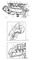
- FIG. 1 is a perspective view of an outside door handle assembly 1 according to the invention shown in disassembled state.
- the outside door handle assembly 1 is intended for a door 2 of a motor vehicle and comprises a handle support 3, which is fastened to the inside of the door 4, and a trough housing 5, which is mountable from the outside of the door 6.
- a handle support 3 For attachment of the handle support 3 on the inside of the door 4, this has in the illustrated embodiment, two mounting lugs 7, for example, hold the head of a screwing, which in turn is in engagement with the handle support 3. In this way, when mounting the Door outside handle assembly 1 of the handle support 3 stably bolted to the inside of the door 4.
- the trough housing 5 is then inserted through a door opening 8 from the outside of the door 6 in the door 2 and then lies with its outer edge portion flush on the outside of the door 6.
- the trough housing 5 extends in the assembled state to the handle support 3 and is used in sections in an opening 9 formed in the handle support 3.
- FIG. 2 again shows an individual part of the inventive outside door handle assembly 1, in which representation now also individual components can be seen, which are fastened in the assembled state to the handle support 3.
- these components are mounted on the handle support before assembly of the handle carrier 3 on the inside of the door 4, which shortens the assembly time and facilitates the assembly as a whole.
- respective lever arms 10 of a handle member 11 are inserted through openings 44 in a shell shell 15 and then into receptacles 12 provided in the handle support 3 before the free ends of the respective lever arms 10 are rotatably connected to respective pivot axes 13 and the upper shell housing 15 on the handle support 3 is fixed.
- the horizontal pivot axes 13 are rotatably mounted on the handle support 3, so that the handle member 11 is mounted pivotally mounted on the handle support 3.
- the pivot axes 13 are each coupled to a trained in the manner of a torsion spring resistance element 14, which is supported on the upper side of the handle support 3 and elastically compressed upon pivoting of the corresponding lever arm 10.
- the grip element 11 mounted on the handle support 3 in this manner is covered by the upper shell housing 15, viewed from the inside of the door 4, at least in the upper area of the handle support 3.
- the lower portion of the handle support 3 and the opening 9 of the handle support 3, however, is covered by the cup-shaped bowl housing 5, which is inserted into the opening 9 of the handle support 3 and secured to the handle support 3 itself.
- FIG. 3 shows that shows a rear view of the handle support with mounted thereon trough housing 5 and upper shell housing 15.
- a mechanical switching element 17 is shown, which is rotatably mounted on a holder 18 of the handle support 3.
- An actuating portion 19 is also rotatably mounted on one of the two pivot axes 13, wherein the actuating portion 19 has an actuating lug 20 which occurs upon pivoting of the pivot axis 13 with a coupling lug 21 of the mechanical switching element 17 for a mechanical door opening operation in operative connection and the mechanical switching element 17th pivoted about the bracket 18.
- an electronic switching element 22 is further provided, which is arranged on a passage opening 23 of the upper shell housing 15, wherein the electronic switching element 22 is a crack plate-like return element 24a is connected upstream.
- the handle support 3 has a lock cylinder receptacle 25 into which a lock cylinder 26 can be fastened detachably for mechanical opening of the corresponding door lock by means of a bayonet connection.
- FIG. 4 shows the triggering of an electronic or mechanical door opening operation certain handle member 11 which is mounted on the handle support 3 as described above and can be actuated only from the outside of the door 6 by a user by this on the handle member 11 in the direction of the door outside 6, ie leading the way in door 2 pulls.
- the grip element 11 has a pushbutton 27 mounted in a pivotable manner and a grip body 28.
- the handle body 28 has at its two longitudinal ends to the above-described lever arms 10, whose free ends are rotatably mounted on the horizontal direction of the pivot axis 13 on the handle support. In this way, the handle member 11 is pivotally connected to the handle support 3.
- the grip body 28 and the push button 27 are mounted together on the respective pivot axes 13, so that the pivot axes 13 represent a common storage for handle body 28 and push button 27, wherein the push button 27 is still additionally rotatable relative to the handle body 28.
- the lever-like push button 27 is rotatably mounted on the handle body 28, so that the push button 27 is actuated and triggered to trigger the electronic door opening operation and at the same time the handle body 28 remains unverschwenkt and unconfirmed.
- a deviating storage of the push button 27 is conceivable.
- the push button 27 has a plurality of horizontally extending pins 29 which define a pivot point 30 for the push button 27 on the handle body 28.
- journal receptacles 31 are provided, in which the pins 29 of the push button 27 can be introduced during assembly.
- the push button 27 is mounted relative to the handle body 28 rotatable about the pivot point 30, wherein the pivot point 30 is displaced with pivoting of the handle body 28 due to the present mechanism.
- the push button 27 is formed as a two-armed lever member with a lever arm-like pressing portion 32 and a lever arm-like release portion 33, wherein the trigger portion 33 has an actuating projection 34.
- a user pulls on the pushing portion 32, whereby the pushing portion 32 rotates about the fulcrum 30.
- the triggering section 33 which serves to activate the electronic switching element 22, also rotates.
- the actuating projection 34 passes through the through hole 23 in the upper shell housing 15 through with the switching element 22 in operative connection and triggers the electronic door opening operation.
- the pressing portion 32 and the trigger portion 33 extend from the pivot point 30 in opposite directions, wherein the push button 27 is rotatable about the pivot point 30.
- the handle body 28 on a lever arm-like effective portion 35.
- the active section 35 is in the rest position of the push button 27 (see, for example FIG. 7 ), ie, in a position in which the pressing portion 32 is not operated, spaced from the pressing portion 32.
- an elastic return element 24b is provided, which is arranged in the assembled state of the outside door handle assembly 1 between the handle body 28 and the push button 27 and formed in the form of a leaf spring.
- FIGS. 5, 6 and 7 an unactuated state of the handle member 11 is shown, whereas the handle member 11 in the FIGS. 8, 9 and 10 for triggering the electric door opening operation and in the FIGS. 11, 12 and 13 is actuated to trigger a mechanical door opening operation.
- the pressing portion 32 of the push button 27 is in the rest position.
- the rest position of the pressing portion 32 of the push button 27 is arranged spaced from the lever arm-like effective portion 35 of the handle body 28.
- This distance between the push button 27 and the handle body 28 or between the pressing portion 32 and the active portion 35 is realized in the illustrated embodiment by the return element 24b, which is disposed between the pressing portion 32 and the active portion 35 and is formed elastically deformable.
- the return element 24a further ensures that the pushbutton 27 is in the rest position.
- the handle body 29 is thus not pivoted about the pivot axes 13, so that the actuating portion 19 is not actuated.
- the handle body 29 assumes a basic position, designed in the manner of a torsion spring resistance elements 14 are provided, which in the unactuated state of the outside door handle assembly 1, the handle body 28 via the lever arms 10 and the horizontal pivot axes 13 in the in the FIGS. 6 and 7 position.
- the user In order for the handle body 28 to be pivoted, the user must apply a force which counteracts the resistance element 14, as will be explained below.
- the user In order to trigger an electronic door opening operation during normal operation of the outside door handle assembly 1, the user must actuate the pushbutton 27 by actuating the push portion 32 of the pushbutton 27 through the access opening 16.
- the operation of the pushing portion 32 in the present case is a pulling toward the vehicle outside.
- the outside door handle assembly 1 In the FIGS. 8, 9 and 10 the outside door handle assembly 1 is now actuated to trigger an electronic door opening operation.
- a push-button 27 is operated by a user by pulling on the pressing portion 32, thereby rotating the push-button 27 about the fulcrum 30.
- the user must apply a force to overcome the resistance of the two return elements 24a and 24b, but in The rule is not very high, because the electronic opening of the door to increase the comfort by a small amount of force on the part of the user. It should be mentioned that, alternatively, only one of the two return elements 24a or 24b can be provided, which seems perfectly sufficient to urge the pushbutton 27 into its rest position.
- the push button 27 is pivoted relative to the handle body 28 to trigger the electronic door opening operation, wherein the handle body 28 itself is not pivoted and is still arranged in its unactuated basic position.
- the push button 27 By the rotation of the push button 27 about the pivot 30 counterclockwise around the push portion 32 of the push button 27 is pivoted in the direction of the active portion 35 of the handle body 28 so that the push button 27 is finally disposed in an operating position in which the pressing portion 32 at the Active section 35 is present.
- the trigger portion 33 of the push button 27 presses against the electronic switching element 22 and thus triggers the electronic door opening operation.
- the handle body 28 is usually not operated, as this would require a disproportionately high force by the user, which is not used at all in a door opening operation under normal conditions by the user.
- the amount of force expended by the user need only be high enough to overcome the force of the return elements 24a and 24b to actuate and rotate the push section 32, but this force is relatively low because of the force of the return elements 24a and 24b should only prevent uncontrolled and unintentional turning of the push button 27 about the pivot point 30. Since the handle body 28 is still not actuated in the electronic door opening process, a rotation of the pivot axes 14 remains off, so that the non-rotatably connected to one of the two pivot axes 14 actuating portion 19 is still not actuated, as from FIG. 8 is apparent.
- the electronic door opening operation requires an existing power supply through the electrical system of the motor vehicle.
- an emergency operation is provided in the outside door handle assembly 1 according to the present invention, which is referred to as a mechanical door opening operation.
- This emergency operation or this mechanical door opening operation is in the FIGS. 11, 12 and 13 shown.
- the push button 27 is again actuated by the user and thereby pivoted about the pivot point 30 such that the pressing portion 32 of the push button 27 is disposed adjacent to the active portion 35 of the handle body 28.
- the actuation force applied by the user is now so great that now also the grip body 28 is pivoted via the actuation of the pushbutton 27.
- the force applied by the user is greater than the force of the resistance elements 14, which counteract a pivoting of the grip body 28.
- the force of the resistance elements 14 is four times higher than the force of the restoring elements 24a and 24b.
- the user in order to initiate a mechanical door opening operation, the user must press the push button 27 with a much higher actuation force than the push button 27 about the pivot point 30, but also the handle body 28 about the pivot point of the pivot axes 13 to pivot.
- the handle body 28 is coupled for movement with the pushbutton 27 and actuated via the push button 27 from the outside of the door 6, wherein the active portion 35 of the handle body 28 and the pressing portion 32 of the push button 27 are pivoted in an emergency operating position to trigger the mechanical door opening operation, in the FIGS. 12 and 13 is shown.
- the pivot point 30 of the push button 27 moves in the direction of the outside door 6, so that the pivot point 30 is not stationary but upon pivoting of the handle body 28 in the direction of the door outside 6 shifts.
- the pressing portion 32 is pivoted beyond the operating position.
- the spring-like resistance elements 14 have a force acting portion 35 of the handle body 28 in its unverschwenkte position, which is greater than the pressing portion 32 of the push button 27 in its rest position urging force.
- FIG. 11 it can be seen activated in the Notbetuschistsposition the motion-coupled to the handle body 28 actuating portion 19 of the handle member 11, the mechanical switching element 17. More specifically, in the emergency operation, the pivot axis 13 is rotated, on which the actuating portion 19 is mounted rotationally fixed.
Landscapes
- Lock And Its Accessories (AREA)
Abstract
Description
Die Erfindung richtet sich auf eine Türaußengriffanordnung eines Kraftfahrzeugs, die einen an der Türinnenseite befestigbaren Griffträger, ein an dem Griffträger gelagertes Griffelement und ein von der Türaußenseite durch einen Türausbruch hindurch montierbares, sich im montierten Zustand bis zum auf der Türinnenseite angeordneten Griffträger erstreckendes und zumindest abschnittsweise das von der Türaußenseite betätigbare Griffelement aufnehmendes Muldengehäuse aufweist, wobei das Griffelement eine zum Auslösen eines elektronischen Türöffnungsvorganges ausgebildete und von der Türaußenseite aus betätigbare Drucktaste aufweist.The invention is directed to an outside door handle assembly of a motor vehicle, which can be fastened to the inside of a door handle carrier, a mounted on the handle support handle member and from the outside of the door through a door outlet mountable, in the assembled state to the arranged on the inside of the door handle carrier extending and at least in sections having the operable from the outside of the door grip member receiving trough housing, wherein the handle member has a trained for triggering an electronic door opening operation and operable from the outside of the door push button.
Eine Türaußengriffanordnung der eingangs bezeichneten Art ist beispielsweise aus der
Eine Kraftfahrzeugtür, deren Schloss mit Hilfe eines mobilen ID-Gebers entriegelt ist, kann durch eine Betätigung des Griffelements geöffnet werden, wobei hierbei die Tür auf mechanische Weise aus dem zuvor entriegelten Schloss gelöst wird, wozu eine gewisse Betätigungskraft seitens des Benutzers aufzubringen ist. Im Sinne der vorliegenden Erfindung ist unter einem "Auslösen eines mechanischen Türöffnungsvorgangs" die vorstehend erläuterte Betätigung des Griffelements zum mechanischen Lösen der Tür aus dem Schloss zu verstehen, wobei diese Art der Türöffnung nur im Notfall eine Rolle spielt, wenn beispielsweise die fahrzeugseitige Elektronik nicht ordnungsgemäß funktioniert. Zur Erhöhung des Komforts ist es aus dem Stand der Technik bekannt, die Tür auf elektronische Weise aus dem zuvor (üblicherweise dann auch elektronisch) entriegelten Schloss zu lösen, wobei hierzu nur eine sehr geringe Betätigungskraft seitens des Benutzers aufzubringen ist. Im Sinne der vorliegenden Erfindung ist unter einem "Auslösen eines elektronischen Türöffnungsvorgangs" die zuletzt beschriebene Betätigung des Griffelements zum elektronischen Lösen der Tür aus dem Schloss zu verstehen, wobei diese Art der Türöffnung den Normalfall darstellt. Bekannte Griffanordnungen, bei denen das Auslösen sowohl eines elektronischen als auch eines mechanischen Türöffnungsvorgangs vorgesehen ist, weisen einen komplizierten Aufbau auf, was die Montage der Türaußengriffanordnung an der Kraftfahrzeugtür erschwert und langwierig gestaltet. Darüber hinaus erfolgt die Montage der einzelnen Bauteile solcher Türaußengriffanordnungen zu gleichen Anteilen sowohl von der Türaußenseite als auch von der Türinnenseite, was nicht nur die Montage, sondern auch Reparaturarbeiten erschwert.A motor vehicle door, whose lock is unlocked by means of a mobile ID transmitter, can be opened by an actuation of the handle element, wherein in this case the door is mechanically released from the previously unlocked lock, for which a certain operating force is applied by the user. For the purposes of the present invention, a "triggering of a mechanical door opening operation" is understood to mean the above-described actuation of the handle element for mechanically releasing the door from the lock, whereby this type of door opening only plays a role in an emergency, for example if the on-board electronics are not functioning properly works. To increase the comfort, it is known from the prior art to solve the door in an electronic manner from the previously unlocked (usually then electronic) lock, which is only a very small actuation force applied by the user. For the purposes of the present invention, a "triggering of an electronic door opening operation" is to be understood as the last-described actuation of the grip element for the electronic release of the door from the lock, this type of door opening representing the normal case. Known handle assemblies in which the triggering of both an electronic and a mechanical door opening operation is provided, have a complicated structure, which makes the mounting of the door outer handle assembly on the vehicle door difficult and tedious. In addition, the assembly of the individual components of such outside door handle assemblies takes place in equal proportions both from the outside of the door and the inside of the door, which not only makes installation difficult, but also repairs.
Der Erfindung liegt die Aufgabe zugrunde eine Lösung zu schaffen, die eine verbesserte Türaußengriffanordnung bereitstellt, die kostengünstig vormontierbar ist und auf konstruktiv einfache Weise an einer Kraftfahrzeugtür befestigt werden kann. Insbesondere soll zur Herstellung des Türgriffs eine möglichst geringe Anzahl von Montageelementen erforderlich sein, so dass die Vormontage mit wenigen Handgriffen durchführbar ist, wobei eine Montage überwiegend entweder von der Türinnen- oder Türaußenseite anzustreben ist.The invention has for its object to provide a solution that provides an improved outside door handle assembly that is inexpensive preassembled and can be attached to a motor vehicle door in a structurally simple manner. In particular, the smallest possible number of mounting elements should be required for the production of the door handle, so that the pre-assembly with a few simple steps is feasible, with an assembly is to strive predominantly either from the inside or outside of the door.
Bei einer Türaußengriffanordnung der eingangs bezeichneten Art wird die Aufgabe erfindungsgemäß dadurch gelöst, dass das Griffelement ferner einen zum Auslösen eines mechanischen Türöffnungsvorganges ausgebildeten und das Griffelement mit dem Griffträger schwenkbeweglich verbindenden Griffkörper aufweist, wobei die Drucktaste relativ zum Griffkörper drehbar gelagert ist.In an outside door handle assembly of the type described above, the object is achieved in that the handle member further comprises a trained for triggering a mechanical door opening operation and the handle member pivotally connected to the handle carrier grip body, wherein the push button is rotatably mounted relative to the handle body.
Vorteilhafte und zweckmäßige Ausgestaltungen und Weiterbildungen der Erfindung ergeben sich aus den Unteransprüchen.Advantageous and expedient refinements and developments of the invention will become apparent from the dependent claims.
Durch die Erfindung wird eine Türaußengriffanordnung bereitgestellt, welche sich durch eine platzsparende Konstruktion auszeichnet und gleichzeitig die Funktionalitäten eines mechanischen und elektronischen Türöffnungsvorgangs bietet. Dabei werden die mechanische und elektronische Wirkungsweise durch ein einziges Griffelement realisiert, was die kompakte Bauweise der Türaußengriffanordnung gemäß der vorliegenden Erfindung kennzeichnet. Dabei ist das die beiden Funktionalitäten erfüllende Griffelement an dem an der Türinnenseite montierbaren Griffträger angebracht, so dass als einziges Bauteil lediglich das Muldengehäuse von der Türaußenseite aus montiert werden muss, was insgesamt die Vormontage der Türaußengriffanordnung vereinfacht, denn wesentliche mechanische und elektronische Bauteile werden an dem an der Türinnenseite angebrachten Griffträger montiert.The invention provides an exterior door handle assembly which is characterized by a space-saving design while providing the functionalities of a mechanical and electronic door opening operation. The mechanical and electronic mode of action are realized by a single handle element, which characterizes the compact design of the outside door handle assembly according to the present invention. In this case, the two functionalities fulfilling grip element is mounted on the inside of the door mountable handle support, so that only the trough housing must be mounted from the outside of the door, which simplifies the pre-assembly of the outside door handle assembly, because essential mechanical and electronic components are on the mounted on the inside of the door mounted handle support.
In Ausgestaltung der Türaußengriffanordnung sieht die Erfindung vor, dass der Griffkörper mit der Drucktaste bewegungsgekoppelt ist und über die Drucktaste von der Türaußenseite aus betätigbar ausgebildet ist. Eine Betätigung der Drucktaste kann dadurch auch den Griffkörper betätigen, wodurch eine Betätigung (Ziehen oder Drücken) der Drucktaste nicht nur einen elektronischen sondern auch einen mechanischen Türöffnungsvorgang bewirken kann. Insbesondere erhöht diese Maßnahme die Flexibilität der Türaußengriffanordnung, denn der mechanische Türöffnungsvorgang, welcher im Notfall bei einem Stromausfall des Bordnetzes von Bedeutung ist, bedingt nach wie vor lediglich eine Betätigung der Drucktaste, die im Fall der Notbetätigung den mit der Drucktaste bewegungsgekoppelten Griffkörper betätigt.In an embodiment of the door outer handle assembly, the invention provides that the handle body is movement-coupled with the pushbutton and is designed to be actuatable via the pushbutton from the exterior of the door. An actuation of the push button can thereby also actuate the handle body, whereby an operation (pulling or pressing) of the push button can not only cause an electronic but also a mechanical door opening operation. In particular, this measure increases the flexibility of the outside door handle assembly, because the mechanical door opening operation, which in an emergency in a Power failure of the electrical system is of importance, still requires only an operation of the push button, which operates in the case of emergency operation the motion-coupled with the push button handle body.
Zur Erhöhung der Kompaktheit und zur Reduzierung der Bauteilanzahl ist es in weiterer Ausgestaltung der Erfindung von Vorteil, wenn der Griffkörper und die Drucktaste an wenigstens einer gemeinsamen Schwenkachse gelagert sind. Obgleich die Lagerung des Griffkörpers und der Drucktaste an einer gemeinsamen Schwenkachse erfolgt, ist die Drucktaste nach wie vor zusätzlich relativ zum Griffkörper drehbar gelagert, so dass die Drucktaste bei gemeinsamer Verschwenkung mit dem Griffkörper um die Schwenkachse herum nach wie vor zusätzlich relativ zum Griffkörper gedreht werden kann.To increase the compactness and to reduce the number of components, it is advantageous in another embodiment of the invention, when the handle body and the push button are mounted on at least one common pivot axis. Although the bearing of the handle body and the push button takes place on a common pivot axis, the push button is still rotatably mounted relative to the handle body, so that the push button together with the handle body around the pivot axis are still additionally rotated relative to the handle body can.
Insbesondere in Anbetracht des zuletzt diskutierten Aspekts kann die Flexibilität und Funktionalität des Griffelements in Ausgestaltung der Erfindung dadurch erhöht werden, wenn die hebelartig ausgebildete Drucktaste drehbar an dem Griffkörper gelagert ist. Diese Ausgestaltung beinhaltet, dass die Drucktaste zum Auslösen des elektronischen Türöffnungsvorgangs betätigt und verschwenkt werden kann, wobei gleichzeitig der Griffkörper unverschwenkt und unbetätigt bleibt.In particular, in view of the last discussed aspect, the flexibility and functionality of the handle member in an embodiment of the invention can be increased if the lever-like design push button is rotatably mounted on the handle body. This embodiment includes that the push button for triggering the electronic door opening operation can be actuated and pivoted, at the same time the handle body remains unverschwenkt and unconfirmed.
In einer weiteren Ausgestaltung der erfindungsgemäßen Türaußengriffanordnung ist vorgesehen, dass zum Auslösen des elektronischen Türöffnungsvorganges die Drucktaste relativ verschwenkt zum unverschwenkten Griffkörper angeordnet ist und dass zum Auslösen des mechanischen Türöffnungsvorganges die Drucktaste verschwenkt und an dem Griffkörper anliegend angeordnet ist und den Griffkörper verschwenkt, wobei zum Auslösen des mechanischen Türöffnungsvorganges das Griffelement mit einer im Vergleich zum Auslösen des elektronischen Türöffnungsvorganges, vorzugsweise vierfach, höheren Betätigungskraft beaufschlagt ist. Um einen ungewünschten mechanischen Türöffnungsvorgang, also eine Notöffnung bei Ausfall der Bordelektronik, zu vermeiden, muss sichergestellt sein, dass eine Verschwenkung und damit einhergehende Betätigung des über die Drucktaste betätigbaren Griffkörpers nur bei Anwendung einer Betätigungskraft erfolgt, die weit über der Kraft liegt, die bei einem elektronischen Öffnungsvorgang im Normalfall angewandt werden muss.In a further embodiment of the door outer handle assembly according to the invention it is provided that for triggering the electronic door opening operation, the push button is relatively pivoted to unverschwenkten handle body is arranged and that for triggering the mechanical door opening operation, the push button is pivoted and disposed adjacent to the handle body and pivots the handle body, wherein for triggering the mechanical door opening operation, the handle element is acted upon in comparison to the triggering of the electronic door opening operation, preferably four times, higher actuation force. To avoid an undesired mechanical door opening operation, ie an emergency opening in the event of a failure of the on-board electronics, it must be ensured that pivoting and concomitant actuation of the handle body which can be actuated via the pushbutton are only possible Application of an actuating force that is far above the force that must be applied in an electronic opening operation normally.
Eine konstruktiv besonders günstige Möglichkeit, die Drucktaste relativ zum Griffkörper drehbar zu lagern, ist in Ausgestaltung der Erfindung dadurch vorgesehen, dass die drehbare Lagerung der Drucktaste an dem Griffkörper von wenigstens einem an der Drucktaste ausgebildeten Zapfen und einer entsprechend am Griffkörper ausgebildeten Zapfenaufnahme gebildet ist.A structurally particularly favorable possibility, rotatably support the push button relative to the handle body is provided in an embodiment of the invention in that the rotatable mounting of the push button on the handle body of at least one pin formed on the push button and a correspondingly formed on the handle body pin receptacle is formed.
Die Erfindung sieht in weiterer Ausgestaltung vor, dass die Drucktaste mit einem hebelarmartigen Drückabschnitt und einem hebelarmartigen, zur Aktivierung eines elektronischen Schaltelementes dienenden Auslöseabschnitt ausgebildet ist, wobei sich der Drückabschnitt und der Auslöseabschnitt von einem Drehpunkt aus in entgegengesetzte Richtungen erstrecken und die Drucktaste um den Drehpunkt drehbar ist. Die Drucktaste ist somit als zweiarmiger Hebel ausgebildet. Diese Ausgestaltung bewirkt, dass bei einer Betätigung des Drückabschnitts dieser sich um den Drehpunkt dreht, wobei gleichzeitig der Auslöseabschnitt hierbei das elektronische Schaltelement aktiviert, wodurch der Türöffnungsvorgang ausgelöst wird.The invention provides in a further embodiment, that the push button is formed with a lever arm-like pressing portion and a lever arm, serving to activate an electronic switching element trigger portion, wherein the push portion and the trigger portion extend from a pivot point in opposite directions and the push button to the fulcrum is rotatable. The push button is thus designed as a two-armed lever. This configuration causes upon actuation of the press section, this rotates about the pivot point, wherein at the same time the triggering section in this case activates the electronic switching element, whereby the door opening operation is triggered.
In einer weiteren Ausgestaltung der Türaußengriffanordnung sieht die Erfindung vor, dass der Griffkörper einen hebelarmartigen Wirkabschnitt aufweist, der in Ruheposition des unbetätigten Drückabschnitts der Drucktaste beabstandet zu dem Drückabschnitt angeordnet ist. Diese Ausgestaltung ermöglicht es, dass infolge des vorhandenen Abstandes zwischen Drückabschnitt und Wirkabschnitt der Griffkörper trotz Betätigung des Drückabschnitts der Drucktaste unbetätigt bleibt, da eine entsprechende Drehung des Drückabschnitts infolge des Abstandes möglich ist.In a further embodiment of the door outer handle arrangement, the invention provides that the handle body has a lever arm-like effective portion, which is arranged in the rest position of the unactuated press section of the pushbutton spaced from the pressing portion. This configuration makes it possible that, due to the existing distance between pressing portion and effective portion of the handle body remains unactuated despite actuation of the pressing portion of the push button, since a corresponding rotation of the pressing portion due to the distance is possible.
Diesbezüglich ist dann für die erfindungsgemäße Türaußengriffanordnung in einer weiteren Ausgestaltung vorgesehen, dass zum Auslösen des elektronischen Türöffnungsvorganges der Drückabschnitt der Drucktaste in Richtung des unverschwenkten Wirkabschnitts des Griffkörpers verschwenkt angeordnet ist, wobei infolge der Verschwenkung der Drucktaste in eine Betätigungsposition der Auslöseabschnitt der Drucktaste das elektronische Schaltelement aktiviert. Der mechanische Türöffnungsvorgang wird nur ausgelöst, wenn das Griffelement, d.h. der Drückabschnitt, mit einer im Vergleich zum Auslösen des elektronischen Türöffnungsvorganges höheren Betätigungskraft beaufschlagt ist. Folglich ist bei Aufbringung einer normalen Betätigungskraft der Drückabschnitt maximal bis zum Wirkabschnitt drehbar, so dass die Drehbewegung der Drucktaste beschränkt ist.In this regard, it is then provided for the door outer handle assembly according to the invention in a further embodiment that for triggering the electronic door opening operation of the pressing portion of the push button in the direction of the unverschwenkten effective portion of the handle body is pivoted, which activates the electronic switching element as a result of the pivoting of the push button in an operating position of the triggering section of the push button. The mechanical door opening operation is triggered only when the handle element, ie the pressing portion, is subjected to a higher compared to the triggering of the electronic door opening operation actuating force. Consequently, upon application of a normal operating force, the pressing portion is maximally rotatable to the working portion, so that the rotational movement of the push-button is restricted.
Im Hinblick auf eine Notbetätigung des Griffelementes sieht die Erfindung in Ausgestaltung der Türaußengriffanordnung weiter vor, dass zum Auslösen des mechanischen Türöffnungsvorganges der Wirkabschnitt des Griffkörpers und der Drückabschnitt der Drucktaste in eine Notbetätigungsposition verschwenkt sind, in welcher der Drückabschnitt über die Betätigungsposition hinaus verschwenkt angeordnet ist und in welcher der Drückabschnitt an dem Wirkabschnitt anliegend angeordnet ist, wobei in der Notbetätigungsposition ein mit dem Griffkörper bewegungsgekoppelter Betätigungsabschnitt des Griffelements ein mechanisches Schaltelement aktiviert. Um das Griffelement in diese Notbetätigungsposition zu bewegen ist es erforderlich, dass der Drückabschnitt mit einer im Vergleich zum Auslösen des elektronischen Türöffnungsvorganges wesentlich größeren und für den Benutzer spürbar höheren Betätigungskraft beaufschlagt ist.With regard to an emergency operation of the handle element, the invention further provides in an embodiment of the door outer handle arrangement that are pivoted to trigger the mechanical door opening operation of the active portion of the handle body and the pressing portion of the push button in an emergency operating position, in which the pressing portion is arranged pivoted beyond the actuating position and in which the pressing portion is disposed adjacent to the operative portion, wherein in the Notbetätigungsposition a movement-coupled with the handle body actuating portion of the handle element activates a mechanical switching element. In order to move the gripping element into this emergency operating position, it is necessary for the pressing section to be subjected to a considerably larger actuating force, which is appreciably greater for the user than for triggering the electronic door opening process.
Damit die Drucktaste nach Betätigung zum Auslösen des mechanischen oder elektronischen Türöffnungsvorganges in ihre ursprüngliche Position zurückkehrt, ist in vorteilhafterweise in Ausgestaltung der Erfindung vorgesehen, dass wenigstens ein eine den Drückabschnitt in seine Ruheposition drängende Kraft aufbringendes Rückstellelement vorgesehen ist.So that the pushbutton returns to its original position after actuation to trigger the mechanical or electronic door opening operation, provision is advantageously made in an embodiment of the invention for at least one restoring element to apply a force urging the push section into its rest position.
Dabei ist es konstruktiv besonders günstig, wenn in Ausgestaltung der erfindungsgemäßen Türaußengriffanordnung das wenigstens eine Rückstellelement zwischen dem Drückabschnitt und dem Wirkabschnitt und/oder zwischen dem hebelartigen Auslöseabschnitt und dem elektronischen Schaltelement angeordnet ist.It is structurally particularly favorable when arranged in an embodiment of the door outer handle assembly according to the invention, the at least one restoring element between the pressing portion and the active portion and / or between the lever-like triggering portion and the electronic switching element.
Um zusätzlich eine Rückstellung des Griffkörpers nach Notbetätigung der Türaußengriffanordnung zu gewährleisten, sieht die Erfindung in weiterer Ausgestaltung vor, das Griffelement wenigstens ein Widerstandselement aufweist, das eine den Wirkabschnitt des Griffkörpers in seine unverschwenkte Position drängende Kraft aufbringt, die größer als eine den Drückabschnitt der Drucktaste in seine Ruheposition drängende Kraft ist. Das Widerstandselement kann beispielsweise eine Drehfeder sein, die eine Gegenkraft bei Verschwenkung des Griffkörpers aufbringt. Diese Gegenkraft ist um ein vielfaches höher als die bei normaler Betätigung zum elektronischen Öffnen aufzuwendende Kraft und entspricht im Betrag der Betätigungskraft, die zur Notbetätigung aufgebracht werden muss.In order to additionally ensure a provision of the handle body after emergency operation of the outside door handle assembly, the invention provides in a further embodiment, the handle member has at least one resistance element that applies a force acting portion of the handle body in its unverschwenkte position urging force greater than the pressing portion of the push button force is urgent in its rest position. The resistance element may for example be a torsion spring, which applies a counterforce when pivoting the handle body. This counterforce is many times higher than the force to be expended during normal operation for electronic opening and corresponds to the amount of operating force that must be applied for emergency operation.
Schließlich ist in Ausgestaltung der Erfindung vorgesehen, dass der mit dem Griffkörper bewegungsgekoppelte Betätigungsabschnitt ein drehfest an dem Griffkörper angebrachtes Hebelelement ist und dass das mechanische Schaltelement einen mit einer Schwenkbewegung des Hebelelements bewegungsgekoppelten und drehbar an dem Trägerelement gelagerten Bowdenzug-Hebel aufweist. Diese Ausgestaltung stellt eine konstruktiv einfache Lösung zur Realisierung einer kostengünstigen Hebelmechanik dar, die im Fall einer Notbetätigung zum Einsatz kommt.Finally, it is provided in an embodiment of the invention that the motion-coupled with the handle body actuating portion is rotatably attached to the handle body lever member and that the mechanical switching element has a motion-coupled with a pivotal movement of the lever member and rotatably mounted on the support member Bowden cable lever. This embodiment represents a structurally simple solution for the realization of a cost-effective lever mechanism, which is used in the case of an emergency operation.
Es versteht sich, dass die vorstehend genannten und nachstehend noch zu erläuternden Merkmale nicht nur in der jeweils angegebenen Kombination, sondern auch in anderen Kombinationen oder in Alleinstellung verwendbar sind, ohne den Rahmen der vorliegenden Erfindung zu verlassen. Der Rahmen der Erfindung ist nur durch die Ansprüche definiert.It is understood that the features mentioned above and those yet to be explained can be used not only in the particular combination given, but also in other combinations or in isolation, without departing from the scope of the present invention. The scope of the invention is defined only by the claims.
Weitere Einzelheiten, Merkmale und Vorteile des Gegenstandes der Erfindung ergeben sich aus der nachfolgenden Beschreibung im Zusammenhang mit der Zeichnung, in der beispielhaft ein bevorzugtes Ausführungsbeispiel der Erfindung dargestellt ist. In der Zeichnung zeigt:
-
Figur 1 -
Figur 2Figur 1 , -
Figur 3 -
Figur 4 -
Figur 5 -
Figur 6Schnittansicht von Figur 5 bei unbetätigtem und in Ruheposition angeordnetem Griffelement, -
Figur 7 eine weitere perspektivischeSchnittansicht von Figur 5 bei unbetätigtem und in Ruheposition angeordnetem Griffelement, -
Figur 8 -
Figur 9 eine perspektivischeSchnittansicht von Figur 8 bei betätigtem Griffelement, -
Figur 10Schnittansicht von Figur 8 bei betätigtem Griffelement, -
Figur 11 -
Figur 12Schnittansicht von Figur 11 bei notbetätigtem Griffelement und -
Figur 13Figur 11
-
FIG. 1 a perspective detail view of an outside door handle assembly according to the invention, -
FIG. 2 an individual perspective view of the essential components of the outside door handle assemblyFIG. 1 . -
FIG. 3 a rear view of a handle support the outside door handle assembly with components mounted thereon, -
FIG. 4 a grip element of the outside door handle assembly in perspective view, -
FIG. 5 a perspective rear view of the handle support with unactuated and arranged in rest position handle element, -
FIG. 6 a perspective sectional view ofFIG. 5 in the unactuated and in rest position arranged handle element, -
FIG. 7 another perspective sectional view ofFIG. 5 in the unactuated and in rest position arranged handle element, -
FIG. 8 a perspective rear view of the handle support with arranged in actuation position handle element, -
FIG. 9 a perspective sectional view ofFIG. 8 with actuated handle element, -
FIG. 10 another perspective sectional view ofFIG. 8 with actuated handle element, -
FIG. 11 a rear perspective view of the handle support in arranged in Notbetätigungsposition handle element, -
FIG. 12 a perspective sectional view ofFIG. 11 at notbetätigtem handle element and -
FIG. 13 another perspective sectional view ofFIG. 11 with emergency operated handle element.
In der
Aus
Die Drucktaste 27 ist als zweiarmiges Hebelelement mit einem hebelarmartigen Drückabschnitt 32 und einem hebelarmartigen Auslöseabschnitt 33 ausgebildet, wobei der Auslöseabschnitt 33 einen Betätigungsvorsprung 34 aufweist. Bei Betätigung der Drucktaste 27 zieht ein Benutzer an dem Drückabschnitt 32, wodurch sich der Drückabschnitt 32 um den Drehpunkt 30 dreht. Dabei dreht sich zusätzlich der Auslöseabschnitt 33, der zur Aktivierung des elektronischen Schaltelements 22 dient. Bei der Drehung der Drucktaste 27 um den Drehpunkt 30 wird der Auslöseabschnitt 33 in Richtung des elektronischen Schaltelements 22 verschwenkt, wodurch der Betätigungsvorsprung 34 durch die Durchgangsöffnung 23 in dem Oberschalengehäuse 15 hindurch mit dem Schaltelement 22 in Wirkverbindung tritt und den elektronischen Türöffnungsvorgang auslöst. Folglich weist die Drucktaste 27 den hebelarmartigen Drückabschnitt 32 und den hebelarmartigen, zur Aktivierung des elektronischen Schaltelementes 22 dienenden Auslöseabschnitt 33 auf. Dabei erstrecken sich der Drückabschnitt 32 und der Auslöseabschnitt 33 von dem Drehpunkt 30 aus in entgegengesetzte Richtungen, wobei die Drucktaste 27 um den Drehpunkt 30 drehbar ist.The
Wie ferner in
Nachstehend wird nun das Zusammenwirken der vorstehend beschriebenen Bauteile der Türaußengriffanordnung 1 erläutert, wobei hierzu in den
Im unbetätigten Zustand der Türaußengriffanordnung 1, wie es in den
Um im Normalbetrieb der Türaußengriffanordnung 1 einen elektronischen Türöffnungsvorgang auszulösen, muss der Benutzer die Drucktaste 27 betätigen, indem er durch die Zugriffsöffnung 16 hindurch den Drückabschnitt 32 der Drucktaste 27 betätigt. Die Betätigung des Drückabschnitts 32 ist in dem vorliegenden Fall ein Ziehen in Richtung der Fahrzeugaußenseite. In den
Der elektronische Türöffnungsvorgang setzt eine vorhandene Stromversorgung durch das Bordnetz des Kraftfahrzeugs voraus. Um aber auch im Fall eines Stromausfalls einen Türöffnungsvorgang auszuführen, ist bei der Türaußengriffanordnung 1 gemäß der vorliegenden Erfindung eine Notbetätigung vorgesehen, die als mechanischer Türöffnungsvorgang bezeichnet wird. Diese Notbetätigung bzw. dieser mechanische Türöffnungsvorgang ist in den
Die vorstehend beschriebene Erfindung ist selbstverständlich nicht auf die beschriebene und dargestellte Ausführungsform beschränkt. Es ist ersichtlich, dass an der in der Zeichnung dargestellten Ausführungsform zahlreiche, dem Fachmann entsprechend der beabsichtigten Anwendung naheliegende Abänderungen vorgenommen werden können, ohne dass dadurch der Bereich der Erfindung verlassen wird. Dabei gehört zur Erfindung alles dasjenige, was in der Beschreibung enthalten und/oder in der Zeichnung dargestellt ist, einschließlich dessen, was abweichend von dem konkreten Ausführungsbeispiel für den Fachmann naheliegt.Of course, the invention described above is not limited to the described and illustrated embodiment. It will be appreciated that numerous modifications which are obvious to a person skilled in the art according to the intended application can be made to the embodiment shown in the drawing without departing from the scope of the invention. It belongs to the invention, all that which is contained in the description and / or shown in the drawing, including what, in deviation from the concrete embodiment obvious to those skilled.
Claims (14)
dadurch gekennzeichnet,
dass das Griffelement (11) ferner einen zum Auslösen eines mechanischen Türöffnungsvorganges ausgebildeten und das Griffelement (11) mit dem Griffträger (3) schwenkbeweglich verbindenden Griffkörper (28) aufweist, wobei die Drucktaste (27) relativ zum Griffkörper (28) drehbar gelagert ist.An outside door handle arrangement (1) of a motor vehicle, which has a handle support (3) which can be mounted on the inside of the door (4), a handle element (11) which is mounted on the handle support (3) and a door outside (6) which can be mounted through an door escape (8). in the mounted state to the arranged on the inside of the door (4) handle carrier (3) and at least partially receiving the outside of the door (6) operable handle element (11) receiving trough housing (5), wherein the handle member (11) for triggering a has an electronic door opening process and can be actuated from the outside of the door (6) by the pushbutton (27),
characterized,
in that the grip element (11) furthermore has a grip body (28) which is designed to trigger a mechanical door opening operation and which pivotably connects the grip element (11) to the grip support (3), wherein the push button (27) is rotatably mounted relative to the grip body (28).
dadurch gekennzeichnet, dass der Griffkörper (28) und die Drucktaste (27) an wenigstens einer gemeinsamen Schwenkachse (13) gelagert sind.Outside door handle assembly (1) according to claim 1 or 2,
characterized in that the handle body (28) and the push button (27) are mounted on at least one common pivot axis (13).
Applications Claiming Priority (1)
| Application Number | Priority Date | Filing Date | Title |
|---|---|---|---|
| DE102013102106.9A DE102013102106A1 (en) | 2013-03-04 | 2013-03-04 | Outside door handle arrangement |
Publications (3)
| Publication Number | Publication Date |
|---|---|
| EP2775076A2 true EP2775076A2 (en) | 2014-09-10 |
| EP2775076A3 EP2775076A3 (en) | 2015-11-18 |
| EP2775076B1 EP2775076B1 (en) | 2019-09-25 |
Family
ID=50190279
Family Applications (1)
| Application Number | Title | Priority Date | Filing Date |
|---|---|---|---|
| EP14156818.8A Active EP2775076B1 (en) | 2013-03-04 | 2014-02-26 | External door handle assembly |
Country Status (3)
| Country | Link |
|---|---|
| EP (1) | EP2775076B1 (en) |
| CN (1) | CN104033050B (en) |
| DE (1) | DE102013102106A1 (en) |
Cited By (5)
| Publication number | Priority date | Publication date | Assignee | Title |
|---|---|---|---|---|
| WO2017129333A1 (en) * | 2016-01-28 | 2017-08-03 | Huf Hülsbeck & Fürst Gmbh & Co. Kg | Door handle system for an electromechanical lock |
| WO2018019723A1 (en) * | 2016-07-25 | 2018-02-01 | Witte Automotive Gmbh | Door handle assembly |
| WO2019120598A1 (en) * | 2017-12-22 | 2019-06-27 | Huf Hülsbeck & Fürst Gmbh & Co. Kg | Motor vehicle door handle arrangement with an operating module |
| WO2019120728A1 (en) * | 2017-12-19 | 2019-06-27 | Huf Hülsbeck & Fürst Gmbh & Co. Kg | Door handle assembly of a motor vehicle |
| WO2020156812A1 (en) * | 2019-01-30 | 2020-08-06 | Bayerische Motoren Werke Aktiengesellschaft | Actuating device for an opening and closing device |
Families Citing this family (5)
| Publication number | Priority date | Publication date | Assignee | Title |
|---|---|---|---|---|
| EP3591151B1 (en) * | 2015-09-09 | 2020-07-22 | U-Shin Italia S.p.A. | Electronic handle for a vehicle door |
| DE102018100654A1 (en) * | 2018-01-12 | 2019-07-18 | Huf Hülsbeck & Fürst Gmbh & Co. Kg | Motor vehicle handle assembly and method for mounting such a motor vehicle handle assembly |
| FR3081489B1 (en) * | 2018-05-25 | 2022-09-09 | U Shin Italia Spa | OPENING HANDLE DEVICE, IN PARTICULAR FOR VEHICLES |
| CN108979369A (en) * | 2018-06-04 | 2018-12-11 | 北京长城华冠汽车科技股份有限公司 | Vehicle door handle mechanism and automobile |
| DE102018117961A1 (en) | 2018-07-25 | 2020-01-30 | Huf Hülsbeck & Fürst Gmbh & Co. Kg | Handle arrangement of a motor vehicle |
Citations (2)
| Publication number | Priority date | Publication date | Assignee | Title |
|---|---|---|---|---|
| DE102006029774A1 (en) | 2006-06-27 | 2008-01-03 | Huf Hülsbeck & Fürst Gmbh & Co. Kg | Gripping device for actuating lock for opening and/or closing of e.g. door, has electronic unit for comfortable handling of gripping device, and arranged in hollow space or U-shaped projection that is present in movable gripping unit |
| DE102010038071A1 (en) | 2010-10-08 | 2012-04-12 | Huf Hülsbeck & Fürst Gmbh & Co. Kg | Outside door handle device |
Family Cites Families (5)
| Publication number | Priority date | Publication date | Assignee | Title |
|---|---|---|---|---|
| FR2753739B1 (en) * | 1996-09-20 | 1998-10-23 | CONTROL HANDLE FOR OPENING A LOCK OF A MOTOR VEHICLE OPENING ELEMENT | |
| AU9143698A (en) * | 1997-12-03 | 1999-06-24 | Robert Bosch Gmbh | A door handle assembly |
| US6406075B1 (en) * | 1999-12-30 | 2002-06-18 | Delphi Technologies, Inc. | Latch handle assembly |
| DE102004058874A1 (en) * | 2004-12-06 | 2006-06-08 | Huf Hülsbeck & Fürst Gmbh & Co. Kg | Outside door handle for a motor vehicle |
| DE102006027473A1 (en) * | 2006-06-12 | 2007-12-13 | Huf Hülsbeck & Fürst Gmbh & Co. Kg | Actuator I |
-
2013
- 2013-03-04 DE DE102013102106.9A patent/DE102013102106A1/en not_active Withdrawn
-
2014
- 2014-02-26 EP EP14156818.8A patent/EP2775076B1/en active Active
- 2014-03-04 CN CN201410077672.2A patent/CN104033050B/en active Active
Patent Citations (2)
| Publication number | Priority date | Publication date | Assignee | Title |
|---|---|---|---|---|
| DE102006029774A1 (en) | 2006-06-27 | 2008-01-03 | Huf Hülsbeck & Fürst Gmbh & Co. Kg | Gripping device for actuating lock for opening and/or closing of e.g. door, has electronic unit for comfortable handling of gripping device, and arranged in hollow space or U-shaped projection that is present in movable gripping unit |
| DE102010038071A1 (en) | 2010-10-08 | 2012-04-12 | Huf Hülsbeck & Fürst Gmbh & Co. Kg | Outside door handle device |
Cited By (5)
| Publication number | Priority date | Publication date | Assignee | Title |
|---|---|---|---|---|
| WO2017129333A1 (en) * | 2016-01-28 | 2017-08-03 | Huf Hülsbeck & Fürst Gmbh & Co. Kg | Door handle system for an electromechanical lock |
| WO2018019723A1 (en) * | 2016-07-25 | 2018-02-01 | Witte Automotive Gmbh | Door handle assembly |
| WO2019120728A1 (en) * | 2017-12-19 | 2019-06-27 | Huf Hülsbeck & Fürst Gmbh & Co. Kg | Door handle assembly of a motor vehicle |
| WO2019120598A1 (en) * | 2017-12-22 | 2019-06-27 | Huf Hülsbeck & Fürst Gmbh & Co. Kg | Motor vehicle door handle arrangement with an operating module |
| WO2020156812A1 (en) * | 2019-01-30 | 2020-08-06 | Bayerische Motoren Werke Aktiengesellschaft | Actuating device for an opening and closing device |
Also Published As
| Publication number | Publication date |
|---|---|
| DE102013102106A1 (en) | 2014-09-04 |
| CN104033050A (en) | 2014-09-10 |
| EP2775076A3 (en) | 2015-11-18 |
| EP2775076B1 (en) | 2019-09-25 |
| CN104033050B (en) | 2019-02-01 |
Similar Documents
| Publication | Publication Date | Title |
|---|---|---|
| EP2775076B1 (en) | External door handle assembly | |
| EP2326781B1 (en) | Lock unit having a multi-part pawl and a spring-loaded blocking pawl | |
| EP2813653B1 (en) | Door handle assembly for a motor vehicle | |
| EP2704922B1 (en) | Locking device | |
| DE102011010797A1 (en) | Motor vehicle door lock | |
| EP2491207A1 (en) | Flush handle device for a door of a vehicle | |
| DE102012011951B4 (en) | Locking device and vehicle seat | |
| EP1842992B1 (en) | Bonnet lock | |
| DE102008021872A1 (en) | Door lock assembly with a single complex damper for a motor vehicle | |
| EP2929114A2 (en) | Lock for a flap or door | |
| WO2018137839A1 (en) | Door handle assembly for a vehicle door | |
| EP3396088A1 (en) | Vehicle door handle | |
| DE102012203734A1 (en) | Lock for a flap or door | |
| WO2014032641A2 (en) | Motor vehicle door | |
| EP3728770B1 (en) | Door handle device for a motor vehicle | |
| WO2020048653A1 (en) | Door handle arrangement for a motor vehicle | |
| DE102012025448A1 (en) | Motor vehicle door lock | |
| DE102007013228A1 (en) | Steering wheel lock device | |
| WO2013189695A1 (en) | Interior door opener for the door lock of a motor vehicle | |
| EP3803006B1 (en) | Door handle assembly for a motor vehicle | |
| DE102020112935A1 (en) | Motor vehicle door handle assembly | |
| EP1267023B1 (en) | Assisted closing device for vehicle door | |
| EP3179021A1 (en) | Door handle assembly for a motor vehicle | |
| EP3670797B1 (en) | Door handle arrangement of a motor vehicle | |
| EP3935245B1 (en) | Motor vehicle lock |
Legal Events
| Date | Code | Title | Description |
|---|---|---|---|
| PUAI | Public reference made under article 153(3) epc to a published international application that has entered the european phase |
Free format text: ORIGINAL CODE: 0009012 |
|
| 17P | Request for examination filed |
Effective date: 20140226 |
|
| AK | Designated contracting states |
Kind code of ref document: A2 Designated state(s): AL AT BE BG CH CY CZ DE DK EE ES FI FR GB GR HR HU IE IS IT LI LT LU LV MC MK MT NL NO PL PT RO RS SE SI SK SM TR |
|
| AX | Request for extension of the european patent |
Extension state: BA ME |
|
| PUAL | Search report despatched |
Free format text: ORIGINAL CODE: 0009013 |
|
| AK | Designated contracting states |
Kind code of ref document: A3 Designated state(s): AL AT BE BG CH CY CZ DE DK EE ES FI FR GB GR HR HU IE IS IT LI LT LU LV MC MK MT NL NO PL PT RO RS SE SI SK SM TR |
|
| AX | Request for extension of the european patent |
Extension state: BA ME |
|
| RIC1 | Information provided on ipc code assigned before grant |
Ipc: E05B 81/90 20140101ALI20151009BHEP Ipc: E05B 79/06 20140101ALI20151009BHEP Ipc: E05B 85/18 20140101AFI20151009BHEP |
|
| R17P | Request for examination filed (corrected) |
Effective date: 20160518 |
|
| RBV | Designated contracting states (corrected) |
Designated state(s): AL AT BE BG CH CY CZ DE DK EE ES FI FR GB GR HR HU IE IS IT LI LT LU LV MC MK MT NL NO PL PT RO RS SE SI SK SM TR |
|
| STAA | Information on the status of an ep patent application or granted ep patent |
Free format text: STATUS: EXAMINATION IS IN PROGRESS |
|
| 17Q | First examination report despatched |
Effective date: 20170529 |
|
| GRAP | Despatch of communication of intention to grant a patent |
Free format text: ORIGINAL CODE: EPIDOSNIGR1 |
|
| STAA | Information on the status of an ep patent application or granted ep patent |
Free format text: STATUS: GRANT OF PATENT IS INTENDED |
|
| INTG | Intention to grant announced |
Effective date: 20190607 |
|
| GRAS | Grant fee paid |
Free format text: ORIGINAL CODE: EPIDOSNIGR3 |
|
| GRAA | (expected) grant |
Free format text: ORIGINAL CODE: 0009210 |
|
| STAA | Information on the status of an ep patent application or granted ep patent |
Free format text: STATUS: THE PATENT HAS BEEN GRANTED |
|
| AK | Designated contracting states |
Kind code of ref document: B1 Designated state(s): AL AT BE BG CH CY CZ DE DK EE ES FI FR GB GR HR HU IE IS IT LI LT LU LV MC MK MT NL NO PL PT RO RS SE SI SK SM TR |
|
| REG | Reference to a national code |
Ref country code: GB Ref legal event code: FG4D Free format text: NOT ENGLISH |
|
| REG | Reference to a national code |
Ref country code: CH Ref legal event code: EP |
|
| REG | Reference to a national code |
Ref country code: DE Ref legal event code: R096 Ref document number: 502014012701 Country of ref document: DE |
|
| REG | Reference to a national code |
Ref country code: AT Ref legal event code: REF Ref document number: 1183974 Country of ref document: AT Kind code of ref document: T Effective date: 20191015 |
|
| REG | Reference to a national code |
Ref country code: IE Ref legal event code: FG4D Free format text: LANGUAGE OF EP DOCUMENT: GERMAN |
|
| REG | Reference to a national code |
Ref country code: NL Ref legal event code: MP Effective date: 20190925 |
|
| PG25 | Lapsed in a contracting state [announced via postgrant information from national office to epo] |
Ref country code: FI Free format text: LAPSE BECAUSE OF FAILURE TO SUBMIT A TRANSLATION OF THE DESCRIPTION OR TO PAY THE FEE WITHIN THE PRESCRIBED TIME-LIMIT Effective date: 20190925 Ref country code: SE Free format text: LAPSE BECAUSE OF FAILURE TO SUBMIT A TRANSLATION OF THE DESCRIPTION OR TO PAY THE FEE WITHIN THE PRESCRIBED TIME-LIMIT Effective date: 20190925 Ref country code: HR Free format text: LAPSE BECAUSE OF FAILURE TO SUBMIT A TRANSLATION OF THE DESCRIPTION OR TO PAY THE FEE WITHIN THE PRESCRIBED TIME-LIMIT Effective date: 20190925 Ref country code: LT Free format text: LAPSE BECAUSE OF FAILURE TO SUBMIT A TRANSLATION OF THE DESCRIPTION OR TO PAY THE FEE WITHIN THE PRESCRIBED TIME-LIMIT Effective date: 20190925 Ref country code: NO Free format text: LAPSE BECAUSE OF FAILURE TO SUBMIT A TRANSLATION OF THE DESCRIPTION OR TO PAY THE FEE WITHIN THE PRESCRIBED TIME-LIMIT Effective date: 20191225 Ref country code: BG Free format text: LAPSE BECAUSE OF FAILURE TO SUBMIT A TRANSLATION OF THE DESCRIPTION OR TO PAY THE FEE WITHIN THE PRESCRIBED TIME-LIMIT Effective date: 20191225 |
|
| REG | Reference to a national code |
Ref country code: LT Ref legal event code: MG4D |
|
| PG25 | Lapsed in a contracting state [announced via postgrant information from national office to epo] |
Ref country code: RS Free format text: LAPSE BECAUSE OF FAILURE TO SUBMIT A TRANSLATION OF THE DESCRIPTION OR TO PAY THE FEE WITHIN THE PRESCRIBED TIME-LIMIT Effective date: 20190925 Ref country code: LV Free format text: LAPSE BECAUSE OF FAILURE TO SUBMIT A TRANSLATION OF THE DESCRIPTION OR TO PAY THE FEE WITHIN THE PRESCRIBED TIME-LIMIT Effective date: 20190925 Ref country code: GR Free format text: LAPSE BECAUSE OF FAILURE TO SUBMIT A TRANSLATION OF THE DESCRIPTION OR TO PAY THE FEE WITHIN THE PRESCRIBED TIME-LIMIT Effective date: 20191226 |
|
| PG25 | Lapsed in a contracting state [announced via postgrant information from national office to epo] |
Ref country code: RO Free format text: LAPSE BECAUSE OF FAILURE TO SUBMIT A TRANSLATION OF THE DESCRIPTION OR TO PAY THE FEE WITHIN THE PRESCRIBED TIME-LIMIT Effective date: 20190925 Ref country code: IT Free format text: LAPSE BECAUSE OF FAILURE TO SUBMIT A TRANSLATION OF THE DESCRIPTION OR TO PAY THE FEE WITHIN THE PRESCRIBED TIME-LIMIT Effective date: 20190925 Ref country code: PT Free format text: LAPSE BECAUSE OF FAILURE TO SUBMIT A TRANSLATION OF THE DESCRIPTION OR TO PAY THE FEE WITHIN THE PRESCRIBED TIME-LIMIT Effective date: 20200127 Ref country code: ES Free format text: LAPSE BECAUSE OF FAILURE TO SUBMIT A TRANSLATION OF THE DESCRIPTION OR TO PAY THE FEE WITHIN THE PRESCRIBED TIME-LIMIT Effective date: 20190925 Ref country code: NL Free format text: LAPSE BECAUSE OF FAILURE TO SUBMIT A TRANSLATION OF THE DESCRIPTION OR TO PAY THE FEE WITHIN THE PRESCRIBED TIME-LIMIT Effective date: 20190925 Ref country code: PL Free format text: LAPSE BECAUSE OF FAILURE TO SUBMIT A TRANSLATION OF THE DESCRIPTION OR TO PAY THE FEE WITHIN THE PRESCRIBED TIME-LIMIT Effective date: 20190925 Ref country code: EE Free format text: LAPSE BECAUSE OF FAILURE TO SUBMIT A TRANSLATION OF THE DESCRIPTION OR TO PAY THE FEE WITHIN THE PRESCRIBED TIME-LIMIT Effective date: 20190925 Ref country code: AL Free format text: LAPSE BECAUSE OF FAILURE TO SUBMIT A TRANSLATION OF THE DESCRIPTION OR TO PAY THE FEE WITHIN THE PRESCRIBED TIME-LIMIT Effective date: 20190925 |
|
| PG25 | Lapsed in a contracting state [announced via postgrant information from national office to epo] |
Ref country code: CZ Free format text: LAPSE BECAUSE OF FAILURE TO SUBMIT A TRANSLATION OF THE DESCRIPTION OR TO PAY THE FEE WITHIN THE PRESCRIBED TIME-LIMIT Effective date: 20190925 Ref country code: IS Free format text: LAPSE BECAUSE OF FAILURE TO SUBMIT A TRANSLATION OF THE DESCRIPTION OR TO PAY THE FEE WITHIN THE PRESCRIBED TIME-LIMIT Effective date: 20200224 Ref country code: SK Free format text: LAPSE BECAUSE OF FAILURE TO SUBMIT A TRANSLATION OF THE DESCRIPTION OR TO PAY THE FEE WITHIN THE PRESCRIBED TIME-LIMIT Effective date: 20190925 Ref country code: SM Free format text: LAPSE BECAUSE OF FAILURE TO SUBMIT A TRANSLATION OF THE DESCRIPTION OR TO PAY THE FEE WITHIN THE PRESCRIBED TIME-LIMIT Effective date: 20190925 |
|
| REG | Reference to a national code |
Ref country code: DE Ref legal event code: R097 Ref document number: 502014012701 Country of ref document: DE |
|
| PG2D | Information on lapse in contracting state deleted |
Ref country code: IS |
|
| PG25 | Lapsed in a contracting state [announced via postgrant information from national office to epo] |
Ref country code: DK Free format text: LAPSE BECAUSE OF FAILURE TO SUBMIT A TRANSLATION OF THE DESCRIPTION OR TO PAY THE FEE WITHIN THE PRESCRIBED TIME-LIMIT Effective date: 20190925 Ref country code: IS Free format text: LAPSE BECAUSE OF FAILURE TO SUBMIT A TRANSLATION OF THE DESCRIPTION OR TO PAY THE FEE WITHIN THE PRESCRIBED TIME-LIMIT Effective date: 20200126 |
|
| PLBE | No opposition filed within time limit |
Free format text: ORIGINAL CODE: 0009261 |
|
| STAA | Information on the status of an ep patent application or granted ep patent |
Free format text: STATUS: NO OPPOSITION FILED WITHIN TIME LIMIT |
|
| 26N | No opposition filed |
Effective date: 20200626 |
|
| REG | Reference to a national code |
Ref country code: CH Ref legal event code: PL |
|
| REG | Reference to a national code |
Ref country code: BE Ref legal event code: MM Effective date: 20200229 |
|
| PG25 | Lapsed in a contracting state [announced via postgrant information from national office to epo] |
Ref country code: MC Free format text: LAPSE BECAUSE OF FAILURE TO SUBMIT A TRANSLATION OF THE DESCRIPTION OR TO PAY THE FEE WITHIN THE PRESCRIBED TIME-LIMIT Effective date: 20190925 Ref country code: LU Free format text: LAPSE BECAUSE OF NON-PAYMENT OF DUE FEES Effective date: 20200226 |
|
| PG25 | Lapsed in a contracting state [announced via postgrant information from national office to epo] |
Ref country code: CH Free format text: LAPSE BECAUSE OF NON-PAYMENT OF DUE FEES Effective date: 20200229 Ref country code: SI Free format text: LAPSE BECAUSE OF FAILURE TO SUBMIT A TRANSLATION OF THE DESCRIPTION OR TO PAY THE FEE WITHIN THE PRESCRIBED TIME-LIMIT Effective date: 20190925 Ref country code: LI Free format text: LAPSE BECAUSE OF NON-PAYMENT OF DUE FEES Effective date: 20200229 |
|
| PG25 | Lapsed in a contracting state [announced via postgrant information from national office to epo] |
Ref country code: IE Free format text: LAPSE BECAUSE OF NON-PAYMENT OF DUE FEES Effective date: 20200226 |
|
| PG25 | Lapsed in a contracting state [announced via postgrant information from national office to epo] |
Ref country code: BE Free format text: LAPSE BECAUSE OF NON-PAYMENT OF DUE FEES Effective date: 20200229 |
|
| REG | Reference to a national code |
Ref country code: AT Ref legal event code: MM01 Ref document number: 1183974 Country of ref document: AT Kind code of ref document: T Effective date: 20200226 |
|
| PG25 | Lapsed in a contracting state [announced via postgrant information from national office to epo] |
Ref country code: AT Free format text: LAPSE BECAUSE OF NON-PAYMENT OF DUE FEES Effective date: 20200226 |
|
| PGFP | Annual fee paid to national office [announced via postgrant information from national office to epo] |
Ref country code: GB Payment date: 20220221 Year of fee payment: 9 |
|
| PG25 | Lapsed in a contracting state [announced via postgrant information from national office to epo] |
Ref country code: TR Free format text: LAPSE BECAUSE OF FAILURE TO SUBMIT A TRANSLATION OF THE DESCRIPTION OR TO PAY THE FEE WITHIN THE PRESCRIBED TIME-LIMIT Effective date: 20190925 Ref country code: MT Free format text: LAPSE BECAUSE OF FAILURE TO SUBMIT A TRANSLATION OF THE DESCRIPTION OR TO PAY THE FEE WITHIN THE PRESCRIBED TIME-LIMIT Effective date: 20190925 Ref country code: CY Free format text: LAPSE BECAUSE OF FAILURE TO SUBMIT A TRANSLATION OF THE DESCRIPTION OR TO PAY THE FEE WITHIN THE PRESCRIBED TIME-LIMIT Effective date: 20190925 |
|
| PGFP | Annual fee paid to national office [announced via postgrant information from national office to epo] |
Ref country code: FR Payment date: 20220221 Year of fee payment: 9 |
|
| PG25 | Lapsed in a contracting state [announced via postgrant information from national office to epo] |
Ref country code: MK Free format text: LAPSE BECAUSE OF FAILURE TO SUBMIT A TRANSLATION OF THE DESCRIPTION OR TO PAY THE FEE WITHIN THE PRESCRIBED TIME-LIMIT Effective date: 20190925 |
|
| P01 | Opt-out of the competence of the unified patent court (upc) registered |
Effective date: 20230507 |
|
| GBPC | Gb: european patent ceased through non-payment of renewal fee |
Effective date: 20230226 |
|
| PG25 | Lapsed in a contracting state [announced via postgrant information from national office to epo] |
Ref country code: GB Free format text: LAPSE BECAUSE OF NON-PAYMENT OF DUE FEES Effective date: 20230226 |
|
| PG25 | Lapsed in a contracting state [announced via postgrant information from national office to epo] |
Ref country code: GB Free format text: LAPSE BECAUSE OF NON-PAYMENT OF DUE FEES Effective date: 20230226 Ref country code: FR Free format text: LAPSE BECAUSE OF NON-PAYMENT OF DUE FEES Effective date: 20230228 |
|
| PGFP | Annual fee paid to national office [announced via postgrant information from national office to epo] |
Ref country code: DE Payment date: 20240229 Year of fee payment: 11 |