EP2775046A1 - Sanitärarmatur mit elektrischem Sensor - Google Patents
Sanitärarmatur mit elektrischem Sensor Download PDFInfo
- Publication number
- EP2775046A1 EP2775046A1 EP14000665.1A EP14000665A EP2775046A1 EP 2775046 A1 EP2775046 A1 EP 2775046A1 EP 14000665 A EP14000665 A EP 14000665A EP 2775046 A1 EP2775046 A1 EP 2775046A1
- Authority
- EP
- European Patent Office
- Prior art keywords
- housing section
- housing
- sanitary fitting
- coupling component
- electrical
- Prior art date
- Legal status (The legal status is an assumption and is not a legal conclusion. Google has not performed a legal analysis and makes no representation as to the accuracy of the status listed.)
- Granted
Links
- 230000008878 coupling Effects 0.000 claims abstract description 50
- 238000010168 coupling process Methods 0.000 claims abstract description 50
- 238000005859 coupling reaction Methods 0.000 claims abstract description 50
- 239000004033 plastic Substances 0.000 claims abstract description 10
- XLYOFNOQVPJJNP-UHFFFAOYSA-N water Substances O XLYOFNOQVPJJNP-UHFFFAOYSA-N 0.000 description 14
- 239000004020 conductor Substances 0.000 description 7
- 239000012799 electrically-conductive coating Substances 0.000 description 3
- 239000000463 material Substances 0.000 description 3
- 230000004913 activation Effects 0.000 description 2
- 230000008901 benefit Effects 0.000 description 2
- 239000011248 coating agent Substances 0.000 description 2
- 238000000576 coating method Methods 0.000 description 2
- 230000009849 deactivation Effects 0.000 description 2
- 238000010292 electrical insulation Methods 0.000 description 2
- 238000011156 evaluation Methods 0.000 description 2
- 238000009413 insulation Methods 0.000 description 2
- 239000002245 particle Substances 0.000 description 2
- 229910001369 Brass Inorganic materials 0.000 description 1
- 239000004743 Polypropylene Substances 0.000 description 1
- 230000015572 biosynthetic process Effects 0.000 description 1
- 239000010951 brass Substances 0.000 description 1
- 230000007797 corrosion Effects 0.000 description 1
- 238000005260 corrosion Methods 0.000 description 1
- 230000001419 dependent effect Effects 0.000 description 1
- 230000000694 effects Effects 0.000 description 1
- 230000005684 electric field Effects 0.000 description 1
- 239000000835 fiber Substances 0.000 description 1
- 210000000245 forearm Anatomy 0.000 description 1
- 239000008187 granular material Substances 0.000 description 1
- 210000004247 hand Anatomy 0.000 description 1
- 238000009434 installation Methods 0.000 description 1
- 238000009428 plumbing Methods 0.000 description 1
- -1 polypropylene Polymers 0.000 description 1
- 229920001155 polypropylene Polymers 0.000 description 1
- 229920001169 thermoplastic Polymers 0.000 description 1
- 239000004416 thermosoftening plastic Substances 0.000 description 1
- 230000007704 transition Effects 0.000 description 1
- 210000000707 wrist Anatomy 0.000 description 1
Images


Classifications
-
- F—MECHANICAL ENGINEERING; LIGHTING; HEATING; WEAPONS; BLASTING
- F16—ENGINEERING ELEMENTS AND UNITS; GENERAL MEASURES FOR PRODUCING AND MAINTAINING EFFECTIVE FUNCTIONING OF MACHINES OR INSTALLATIONS; THERMAL INSULATION IN GENERAL
- F16K—VALVES; TAPS; COCKS; ACTUATING-FLOATS; DEVICES FOR VENTING OR AERATING
- F16K31/00—Actuating devices; Operating means; Releasing devices
- F16K31/02—Actuating devices; Operating means; Releasing devices electric; magnetic
-
- E—FIXED CONSTRUCTIONS
- E03—WATER SUPPLY; SEWERAGE
- E03C—DOMESTIC PLUMBING INSTALLATIONS FOR FRESH WATER OR WASTE WATER; SINKS
- E03C1/00—Domestic plumbing installations for fresh water or waste water; Sinks
- E03C1/02—Plumbing installations for fresh water
- E03C1/04—Water-basin installations specially adapted to wash-basins or baths
- E03C1/0404—Constructional or functional features of the spout
-
- E—FIXED CONSTRUCTIONS
- E03—WATER SUPPLY; SEWERAGE
- E03C—DOMESTIC PLUMBING INSTALLATIONS FOR FRESH WATER OR WASTE WATER; SINKS
- E03C1/00—Domestic plumbing installations for fresh water or waste water; Sinks
- E03C1/02—Plumbing installations for fresh water
- E03C1/05—Arrangements of devices on wash-basins, baths, sinks, or the like for remote control of taps
- E03C1/055—Electrical control devices, e.g. with push buttons, control panels or the like
Definitions
- the present invention relates to a sanitary fitting which is at least partially sensitive to touch.
- the invention relates to a sanitary fitting having a proximity sensor and / or a touch sensor, preferably in the configuration of a capacitive sensor.
- a pre-set volume quantity and temperature of the water can be dispensed when touching or approaching a predetermined area of the housing.
- operating elements can be provided with which then an optionally adapted volume flow or another temperature can be set subsequently.
- the so-called faucet is at least partially formed as a capacitive sensor.
- a sanitary fitting is to be specified, which realizes such an electrical connection between relatively moving components of the sanitary fitting in a technically simple manner.
- the sanitary fitting should be particularly durable and can be operated comfortably.
- the sanitary fitting has at least a first housing portion and a second housing portion, which are arranged to be movable relative to one another, wherein the first housing portion forms an electrical sensor together with the second housing portion. Furthermore, an electrically conductive coupling component is provided between the first housing section and the second housing section.
- the coupling component in this case comprises an electrically conductive plastic.
- the sanitary fitting is a base to be mounted firmly on the washstand (a housing section) and a faucet (another housing section) which is movable, in particular rotatable and / or pivotable.
- both housing sections are provided to enclose a part of the watercourse up to the outlet mouth.
- at least one housing section it is possible for at least one housing section to form an (electrically) insulated rigid water conduit, but it is also possible for at least one of the housing sections to receive a flexible water conduit, in particular a hose.
- the two mutually movable components together form a (single) sensor, in particular in the manner of a capacitive sensor.
- a single component of the housing is designed as a sensitive surface
- the two mutually movable components together form a (single) sensor, in particular in the manner of a capacitive sensor.
- both housing sections are at the same electrical potential.
- this can also be avoided be moved that the electrical contact of the movable housing portion in the interior of the housing portion and then forwarded in the other housing portion, for example.
- the invention is based on the concept that the electrical contact directly / indirectly passes from one housing section to the other, and then can be removed from the other housing section. This is preferably the fixed component, so that there are no problems in the electrical contacting and forwarding of the electrical signal more.
- an electrically conductive coupling member is provided between the first housing portion and the second housing portion.
- the electrically conductive coupling component is in particular in an electrically conductive manner both with the first housing portion and with the second housing portion in contact.
- the coupling component may accordingly be located on the outside, on the inside and / or between the housing sections. In principle, it is also possible for certain regions of the coupling component to be electrically insulated in order to prevent the contact with neighboring components, if necessary.
- the coupling member is preferably designed so that it acts equally in the connecting portion around the housing, so realized over the circumference of the housing portion same effect with respect to the electrical contact.
- a coupling part in such a coupling part is preferred that it forms an inner guide sleeve for the at least first housing portion or the second housing portion.
- the two housing sections form a type of pipe socket in the region of the connection region.
- the coupling member is just in this designed so that it can dip into the first housing portion and / or the second housing portion and has a shape that these submerged areas form an inner sleeve on the first housing portion and / or the second housing portion guide sleeve. It is preferred that the coupling component equally forms a guide sleeve for the first housing portion and the second housing portion, so that in particular an axial alignment of the two housing sections is provided to each other via the coupling member. This has particular advantages for the durability and / or installation of the sanitary fitting.
- the coupling component comprises an electrically conductive plastic.
- the coupling component it is fundamentally possible for the coupling component to have an electrically conductive coating and / or at least one electrically conductive conductor element and / or a homogeneously electrically conductive structure.
- An electrically conductive coating is preferably provided at the (outer) locations in which the adjacent components, in particular the adjacent housing portion, do not perform a relative movement to the coupling component.
- the conductor elements can be designed in the manner of webs, printed conductors or the like.
- the plastic is preferably formed with a thermoplastic.
- PP-EL electrically conductive polypropylene
- This material is specially equipped with electrically conductive particles, which are distributed in the plastic.
- the coupling component bridges a gap between the first housing section and the second housing section in the direction of a central axis.
- the coupling component bridges, for example, a gap between the two housing sections or the coupling component spaced from the first housing portion of the second housing portion.
- the region of the coupling component which is arranged in this gap contacts both housing sections in the axial direction.
- the coupling component simultaneously forms an inner guide sleeve and also extends into the gap between the first housing portion and the second housing portion.
- the coupling component forms a seal between the first housing portion and the second housing portion.
- this seal can fulfill the function of minimizing or even completely eliminating potential noise formation during the relative movement of the two housing sections relative to one another.
- an electrically decoupled operating lever is provided on the first housing section or on the second housing section.
- the operating lever cooperates in particular with a mixer tap and thus allows the regulation of the water flow and / or the water temperature.
- the operating lever is in particular fixed only on one of the two housing sections, wherein the operating lever itself is electrically decoupled from the sensitive surface of the housing sections.
- a touch of the operating lever does not lead to a sensitive deactivation / activation the water flow, such as a contact in the region of the housing sections.
- the electrical sensor is a capacitive proximity sensor or capacitive touch sensor.
- the electrical resistance of the coupling component is less than 30,000 ohms [30 k ⁇ ], in particular less than 10,000 ohms [10 k ⁇ ].
- the entire outer surface of the first housing section and the second housing section (and possibly of the coupling component) represents an electrode of the capacitive touch sensor.
- a control unit which cooperates with the electrical sensor and can activate or deactivate at least one valve of a watercourse.
- This is preferably an electric valve which releases or closes the water passage in dependence on the evaluation of the electrical sensor by means of the control unit.
- at least one storage element is provided in the control unit, which can archive the state of the valve and / or a mixing cartridge in order to adjust it again when activated again.
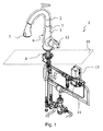
- Fig. 1 shows schematically and teilperspektivisch an installed sanitary fitting 1, which is here, for example.
- a washstand 19 On a washstand 19 is mounted. Above the washstand 19, the first housing section 2 and the second housing section 3 are positioned, between which a coupling component 7 is arranged.
- the first housing section 2 and the second housing section 3 form a kind of faucet, wherein near the first housing section 2 and an outlet opening 5 is arranged for the water.
- the outlet opening 5 is fixedly connected to the first housing section 2, but it is also possible that the outlet opening 5 is formed with a jet former of a hose, in which case the outlet opening 5 and the hose are electrically insulated from the first housing section 2 are arranged.
- an operating lever 12 Protruding laterally from the second housing section 3, an operating lever 12 is formed. This is electrically isolated from the second housing portion 3 attached.
- first housing section 2 can be rotated relative to the second housing section 3.
- both the first housing portion 2 and the second housing portion 3 are sensitive to contact, so form a common (single) electrical sensor 6, as in particular by the dash-dot-dash line in Fig. 1 is illustrated.
- the watercourse 4 is housed.
- the necessary water connections, valves and a control unit 13 are provided below the washstand 19, the necessary water connections, valves and a control unit 13 are provided.
- the control unit 13 is in particular in electrical contact with the first housing section 2 and the second housing section 3.
- the control unit 13 recognizes when the electric field changes due to contact of the first housing section 2 or the second housing section 3 and accordingly switches an electric valve 14 with the result that the inflow of water is either initiated or stopped.
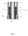
- Fig. 2 shows in section a first embodiment variant of the sanitary fitting in the region of the transition from the first housing section 2 to the second housing section 3.
- the two housing sections which are designed here in the manner of pipe sockets, form a substantially flush outer surface 22 and are mutually frontally or axially ( aligned in the direction of the central axis 10).
- the first housing section 2 and the second housing section 3 are in electrical contact with each other.
- an electrical coupling component 7 is provided, which reliably realizes electrical contact between the first housing section 2 and the second housing section 3.
- the electrical coupling component 7 can in this case support the electrical contact or even ensure it, if a mechanical contact between the housing components themselves is not given (more).
- an electrical insulation 15 is provided, which optionally also forms a holding and / or alignment function with respect to at least one of the two housing sections.
- the electrical insulation 15 applies in particular to internal components, such as here, for example, designed as a hose 16 watercourse 4. Suitable seals 11 may be provided here between the insulation and the housing sections.
- a pickup 20 eg made of brass
- Fig. 3 is a further embodiment shown, in which case in particular the internal component groups of the two housing sections 2, 3 is not discussed in detail.
- This is embodied essentially in the manner of a sleeve 23, with a circumferential, centrally arranged collar 24.
- the regions extending in the direction of the central axis 10 form, in particular, a guide sleeve 8, which extends through an inner sleeve Plant on the first housing portion 2 and the second housing portion 3 allows an alignment of these two components to each other and also realized a secure contact with both housing sections.
- the collar 24 of the coupling member 7 extends into a gap 9 between the first housing portion 2 and the second housing portion 3, so that the coupling member 7, the two housing sections also axially spaced apart.
- the intimate contact of the coupling member 7 in the region of the gap 9 also ensures that at the same time a circumferential Seal 11 is formed.
- the outer surface 22 of the housing sections 2, 3 and of the coupling component 7 forms a common electrical sensor 6, in particular a capacitive touch sensor.
- the electrical signal can be transmitted without problems to the stationary second housing section 3 via an electrical line 21 of the control unit 13.
- the coupling component 7 is preferably formed in one piece, wherein it is preferably formed with electrically conductive plastic.
- Fig. 3 and Fig. 4 show possible embodiments of the coupling member 7, in which case the area between or in the immediate vicinity of the connection region between the first housing section 2 and the second housing section 3 is illustrated in detail.
- Fig. 4 is the coupling member 7, for example, formed with plastic, wherein it is carried out in predetermined areas with an electrically conductive coating 17 and / or electrical conductor elements 18. While a coating 17 is provided only on the surface of the coupling component 7, the electrical conductor elements 18 at least partially penetrate the base material of the coupling element 7 and thus allow a passage of current through regions of the coupling component 7.
- the electrical conductor elements 18 are homogeneously distributed in the material (eg, in the manner of a granulate), so that a homogeneous structure is achieved.
- conductive fibers, particles or the like may be provided which are in electrical contact with each other stand and thus also a Strom twist (directed and / or undirected) can realize.
- the proposed here sanitary fitting thus solves the problems initially set in a technically simple and effective manner.
Landscapes
- Engineering & Computer Science (AREA)
- Health & Medical Sciences (AREA)
- Life Sciences & Earth Sciences (AREA)
- Hydrology & Water Resources (AREA)
- Public Health (AREA)
- Water Supply & Treatment (AREA)
- General Engineering & Computer Science (AREA)
- Mechanical Engineering (AREA)
- Domestic Plumbing Installations (AREA)
Abstract
Description
- Die vorliegende Erfindung betrifft eine Sanitärarmatur, die zumindest teilweise gegenüber Berührung sensitiv ist. Insbesondere betrifft die Erfindung eine Sanitärarmatur, die einen Näherungssensor und/oder einen Berührungssensor aufweist, bevorzugt in der Ausgestaltung eines kapazitiven Sensors.
- Es sind Sanitärarmaturen bekannt, für deren Aktivierung bzw. Deaktivierung nicht die Betätigung eines konkreten Hebels erforderlich ist, sondern die auf die Berührung im Bereich eines Gehäuses der Sanitärarmatur Wasser austreten lassen oder einen bestehenden Wasserfluss wieder verschließen. Hierfür wird insbesondere dem Bediener die Möglichkeit eingeräumt, durch Berühren eines Gehäuseteils mit dem Handrücken, dem Handgelenk oder dem Unterarm das Ausströmen von Wasser zu erreichen. Dies beinhaltet insbesondere den Vorteil, dass die Armatur selbst sauber und ggf. keimfrei gehalten werden kann, insbesondere wird ein Kontakt der Sanitärarmatur mit verschmutzten Händen vermieden.
- Hierbei ist insbesondere vorgesehen, dass bei der Berührung bzw. Annäherung an einen vorgegebenen Bereich des Gehäuses eine voreingestellte Volumenmenge und Temperatur des Wassers abgegeben wird. Zusätzlich können Bedienungselemente vorgesehen sein, mit denen dann ein ggf. angepasster Volumenstrom bzw. eine andere Temperatur nachträglich eingestellt werden können. Zur Realisierung dieser Funktion ist bekannt, einen Bereich des Gehäuses nach Art eines kapazitiven Berührungssensors auszubilden. Bevorzugt wird hierbei der sogenannte Wasserhahn zumindest teilweise als kapazitiver Sensor ausgebildet. Durch eine Berührung dieses Gehäuseabschnitts wird der elektrische Widerstand verändert, was mittels einer entsprechenden Kontrolleinheit ausgelesen werden kann. Diese Kontrolleinheit kann dann mindestens ein Ventil der Wasserzufuhr aktivieren bzw. deaktivieren.
- Da der sensitive Bereich für den Bediener der Sanitärarmatur leicht zugänglich sein soll, hat sich hier ein Abschnitt des Wasserhahns als bevorzugt herausgestellt. Problematisch ist hierbei jedoch, dass gerade dieser Gehäuseabschnitt vielfach beweglich ausgeführt ist, so dass eine elektrische Verbindung zwischen diesem sensitiven Gehäuseabschnitt und der Kontrolleinheit und/oder der elektrischen Erde über Bewegungsgrenzen hinweg ausgebildet sein muss.
- Bei dieser elektrischen Verbindung sind besonders hohe Anforderungen an die Beweglichkeit, Dauerhaltbarkeit und/oder Korrosionsbeständigkeit zu stellen. Die hierfür ggf. bekannten Lösungen sind entweder mit einer hohen Teilevielzahl, einer aufwendigen Montage und/oder einer problembehafteten messtechnischen Auswertung verbunden.
- Hiervon ausgehend ist es Aufgabe der vorliegenden Erfindung, die mit Bezug auf den Stand der Technik geschilderten Probleme zumindest teilweise zu lösen. Insbesondere soll eine Sanitärarmatur angegeben werden, die in technisch einfacher Weise eine solche elektrische Verbindung zwischen relativ zueinander bewegten Bauteilen der Sanitärarmatur realisiert. Gleichzeitig soll die Sanitärarmatur besonders dauerhaltbar sein und komfortabel betrieben werden können.
- Diese Aufgaben werden gelöst mit einer Sanitärarmatur gemäß den Merkmalen des Patentanspruchs 1. Vorteilhafte Ausgestaltungen der Erfindung sind in den abhängigen Patentansprüchen angegeben. Es ist darauf hinzuweisen, dass die in den Patentansprüchen einzeln aufgeführten Merkmale in beliebiger, technologisch sinnvoller Weise miteinander kombiniert werden können und weitere Ausgestaltungen der Erfindung aufzeigen. Die Beschreibung, insbesondere im Zusammenhang mit den Figuren, erläutert diese Merkmale und gibt zusätzliche Ausführungsbeispiele an.
- Die Sanitärarmatur weist zumindest einen ersten Gehäuseabschnitt und einen zweiten Gehäuseabschnitt auf, die beweglich zueinander angeordnet sind, wobei der erste Gehäuseabschnitt zusammen mit dem zweiten Gehäuseabschnitt einen elektrischen Sensor bildet. Weiterhin ist zwischen dem ersten Gehäuseabschnitt und dem zweiten Gehäuseabschnitt ein elektrisch leitendes Kopplungsbauteil vorgesehen. Das Kopplungsbauteil umfasst hierbei einen elektrisch leitenden Kunststoff.
- Bei der Sanitärarmatur handelt es sich insbesondere um eine fest am Waschtisch zu montierende Basis (ein Gehäuseabschnitt) und einen dazu beweglich, insbesondere drehbar und/oder verschwenkbar, angeordneten Wasserhahn (anderer Gehäuseabschnitt). Insbesondere sind beide Gehäuseabschnitte dazu vorgesehen, einen Teil des Wasserlaufs bis hin zur Austrittsmündung einzufassen. Hierfür ist möglich, dass mindestens ein Gehäuseabschnitt eine (elektrisch) isolierte starre Wasserleitung bildet, es ist aber auch möglich, dass zumindest einer der Gehäuseabschnitte eine flexible Wasserleitung, insbesondere einen Schlauch, aufnimmt.
- Während bislang insbesondere das Konzept verfolgt wurde, dass nur ein einzelnes Bauteil des Gehäuses als sensitive Oberfläche ausgebildet ist, wird hier nun vorgeschlagen, dass die beiden gegeneinander beweglichen Bauteile zusammen einen (einzelnen) Sensor bilden, insbesondere nach Art eines kapazitiven Sensors. Das heißt mit anderen Worten insbesondere, dass beide Gehäuseabschnitte auf dem gleichen elektrischen Potential liegen. Insbesondere kann so auch vermieden werden, dass der elektrische Kontakt des beweglichen Gehäuseabschnitts im Inneren des Gehäuseabschnitts verlegt und dann in den anderen Gehäuseabschnitt bspw. mittels eines Kabels weitergeleitet wird. Ebenso können innenliegende, komplexe und störanfällige Schleifkontakte vermieden werden. Insbesondere geht die Erfindung von dem Konzept aus, dass die elektrische Kontaktierung direkt/mittelbar von einem Gehäuseabschnitt auf den anderen übergeht, und dann von dem anderen Gehäuseabschnitt abgenommen werden kann. Dieses ist bevorzugt das feststehende Bauteil, so dass sich hier keine Probleme bei der elektrischen Kontaktierung und Weiterleitung des elektrischen Signals mehr ergeben.
- In diesem Zusammenhang ist weiter vorgesehen, dass zwischen dem ersten Gehäuseabschnitt und dem zweiten Gehäuseabschnitt ein elektrisch leitendes Kopplungsbauteil vorgesehen ist. Das elektrisch leitende Kopplungsbauteil ist insbesondere in elektrisch leitender Weise sowohl mit dem ersten Gehäuseabschnitt als auch mit dem zweiten Gehäuseabschnitt in Kontakt. Das Kopplungsbauteil kann sich demnach außenanliegend, innenanliegend und/oder zwischen den Gehäuseabschnitten befinden. Grundsätzlich ist auch möglich, dass bestimmte Bereiche des Kopplungsbauteils elektrisch isoliert sind, um hier ggf. den Kontakt zu benachbarten Bauteilen zu unterbinden. Das Kopplungsbauteil ist bevorzugt so gestaltet, dass es im Verbindungsabschnitt um das Gehäuse herum gleichermaßen wirkt, also eine über den Umfang des Gehäuseabschnitts gleiche Wirkung hinsichtlich des elektrischen Kontakts realisiert.
- Bei einem solchen Kopplungsteil ist bevorzugt, dass es eine innere Führungshülse für den zumindest ersten Gehäuseabschnitt oder den zweiten Gehäuseabschnitt bildet. Hierbei wird insbesondere davon ausgegangen, dass die beiden Gehäuseabschnitte im Bereich des Verbindungsbereichs eine Art Rohrstutzen ausbilden.
- Das Kopplungsbauteil ist gerade in diesem so gestaltet, dass es in den ersten Gehäuseabschnitt und/oder den zweiten Gehäuseabschnitt eintauchen kann und eine Gestalt hat, dass diese eintauchenden Bereiche eine innen am ersten Gehäuseabschnitt und/oder dem zweiten Gehäuseabschnitt anliegende Führungshülse bilden. Bevorzugt ist, dass das Kopplungsbauteil gleichermaßen eine Führungshülse für den ersten Gehäuseabschnitt und den zweiten Gehäuseabschnitt ausbildet, so dass insbesondere eine axiale Ausrichtung der beiden Gehäuseabschnitte zueinander über das Kopplungsbauteil bereitgestellt ist. Dies hat insbesondere Vorteile für die Dauerhaltbarkeit und/oder die Montage der Sanitärarmatur.
- Außerdem ist auch vorgesehen, dass das Kopplungsbauteil einen elektrisch leitenden Kunststoff umfasst. Hierbei ist grundsätzlich möglich, dass das Kopplungsbauteil eine elektrisch leitende Beschichtung und/oder mindestens ein elektrisch leitendes Leiterelement und/oder einen homogen elektrisch leitenden Aufbau aufweist. Somit ist es möglich, das Kopplungsbauteil mit separaten, verschiedenen Funktionsbereichen auszugestalten. Ebenso ist jedoch möglich, ein Multifunktionsbauteil mit einem homogenen Aufbau des Kunststoff-Bauteils zu erreichen. Eine elektrisch leitende Beschichtung ist bevorzugt an den (äußeren) Stellen vorgesehen, bei denen die benachbarten Bauteile, insbesondere der benachbarte Gehäuseabschnitt, keine Relativbewegung zu dem Kopplungsbauteil ausführen. Die Leiterelemente können nach Art von Stegen, aufgedruckten Leiterbahnen oder Ähnlichem ausgeführt sein. Der Kunststoff ist bevorzugt mit einem Thermoplast gebildet. Als Beispiel für einen elektrisch leitenden Kunststoff, der einen homogenen Aufbau aufweist, sei hier PP-EL (elektrisch leitendes Polypropylen) angeführt. Dieses Material wird speziell mit elektrisch leitfähigen Partikeln ausgerüstet, welche in dem Kunststoff verteilt angeordnet sind.
- Weiter wird auch vorgeschlagen, dass das Kopplungsbauteil einen Spalt zwischen dem ersten Gehäuseabschnitt und dem zweiten Gehäuseabschnitt in Richtung einer Zentralachse überbrückt. Damit überbrückt das Kopplungsbauteil bspw. einen Spalt zwischen den beiden Gehäuseabschnitten bzw. das Kopplungsbauteil beabstandet den ersten Gehäuseabschnitt von dem zweiten Gehäuseabschnitt. Insbesondere berührt der Bereich des Kopplungsbauteils, der in diesem Spalt angeordnet ist, beide Gehäuseabschnitte in axialer Richtung.
- Ganz besonders bevorzugt ist, dass das Kopplungsbauteil gleichzeitig eine innere Führungshülse ausbildet und sich zudem in den Spalt zwischen dem ersten Gehäuseabschnitt und dem zweiten Gehäuseabschnitt erstreckt.
- Darüber hinaus wird als vorteilhaft angesehen, dass das Kopplungsbauteil eine Dichtung zwischen dem ersten Gehäuseabschnitt und dem zweiten Gehäuseabschnitt bildet. Hierbei wird insbesondere vermieden, dass in die Gehäuseabschnitte bzw. aus den Gehäuseabschnitten heraus Feuchtigkeit übertreten kann. Weiterhin kann diese Dichtung die Funktion erfüllen, eine potentielle Geräuschbildung bei der Relativbewegung der beiden Gehäuseabschnitte zueinander zu minimieren oder gar vollständig zu beseitigen.
- Weiterhin wird als vorteilhaft angesehen, dass am ersten Gehäuseabschnitt oder am zweiten Gehäuseabschnitt ein elektrisch entkoppelter Bedienungshebel vorgesehen ist. Der Bedienungshebel wirkt insbesondere mit einer Mischbatterie zusammen und erlaubt insofern die Regulierung des Wasserstroms und/oder der Wassertemperatur. Der Bedienungshebel ist insbesondere nur an einem der beiden Gehäuseabschnitte fixiert, wobei der Bedienungshebel selbst elektrisch von der sensitiven Oberfläche der Gehäuseabschnitte entkoppelt ist. Insbesondere führt eine Berührung des Bedienungshebels nicht zu einer sensitiven Deaktivierung/Aktivierung des Wasserstroms, wie ein Kontakt im Bereich der Gehäuseabschnitte.
- Weiterhin ist bevorzugt, dass der elektrische Sensor ein kapazitiver Näherungssensor oder kapazitiver Berührungssensor ist. Insbesondere für den Fall, dass die Gehäuseabschnitte als kapazitive Berührungssensoren ausgeführt sind, ist bevorzugt, dass der elektrische Widerstand des Kopplungsbauteils kleiner 30.000 Ohm [30 kΩ], insbesondere kleiner 10.000 Ohm [10 kΩ] ist. Insbesondere ist bevorzugt, dass die gesamte äußere Oberfläche des ersten Gehäuseabschnitts und des zweiten Gehäuseabschnitts (und ggf. des Kopplungsbauteils) eine Elektrode des kapazitiven Berührungssensors darstellt.
- Als vorteilhaft wird hier auch angesehen, dass eine Kontrolleinheit vorgesehen ist, die mit dem elektrischen Sensor zusammenwirkt und mindestens ein Ventil eines Wasserlaufs aktivieren oder deaktivieren kann. Dabei handelt es sich bevorzugt um ein elektrisches Ventil, welches in Abhängigkeit von der Auswertung des elektrischen Sensors mittels der Kontrolleinheit den Wasserlauf freigibt oder verschließt. Dabei ist in der Kontrolleinheit bevorzugt mindestens ein Speicherelement vorgesehen, das den Zustand des Ventils und/oder einer Mischkartusche archivieren kann, um diesen bei einer erneuten Aktivierung wieder gleichermaßen einzustellen.
- Die Erfindung sowie das technische Umfeld werden nachfolgend anhand der Figuren näher erläutert. Es ist darauf hinzuweisen, dass die Figuren schematischer Natur sind. Weiterhin ist anzumerken, dass in den Figuren gleiche Bauteile auch mit gleichen Bezugszeichen versehen sind. Jedenfalls sollen die in den Figuren dargestellten Ausführungsbeispiele die Erfindung als solches nicht beschränken. Es zeigen:
- Fig. 1
- einen Aufbau einer Ausführungsvariante der Sanitärarmatur,
- Fig. 2
- ein Detail einer weiteren Ausführungsvariante der Sanitärarmatur im Bereich eines Kopplungsbauteils,
- Fig. 3
- ein Detail einer weiteren Ausführungsvariante im Bereich eines Kopplungsbauteils,
- Fig. 4
- eine Einzelheit eines Kopplungsbauteils, und
- Fig. 5
- eine weitere Einzelheit einer anderen Ausführungsform des Kopplungsbauteils.
-
Fig. 1 zeigt schematisch und teilperspektivisch eine installierte Sanitärarmatur 1, die hier bspw. auf einem Waschtisch 19 montiert ist. Oberhalb des Waschtischs 19 sind der erste Gehäuseabschnitt 2 und der zweite Gehäuseabschnitt 3 positioniert, zwischen denen ein Kopplungsbauteil 7 angeordnet ist. Bei der hier gezeigten Ausführungsform bilden der erste Gehäuseabschnitt 2 und der zweite Gehäuseabschnitt 3 eine Art Wasserhahn aus, wobei nahe des ersten Gehäuseabschnitts 2 auch eine Austrittsmündung 5 für das Wasser angeordnet ist. Hierbei ist grundsätzlich möglich, dass die Austrittsmündung 5 fest mit dem ersten Gehäuseabschnitt 2 verbunden ist, es ist aber auch möglich, dass die Austrittsmündung 5 mit einem Strahlbildner eines Schlauchs gebildet ist, wobei dann die Austrittsmündung 5 und der Schlauch elektrisch isoliert zu dem ersten Gehäuseabschnitt 2 angeordnet sind. Seitlich vom zweiten Gehäuseabschnitt 3 hervorstehend ist ein Bedienungshebel 12 ausgebildet. Dieser ist elektrisch isoliert gegenüber dem zweiten Gehäuseabschnitt 3 angebracht. - Wie mit dem Pfeil angedeutet, lässt sich der erste Gehäuseabschnitt 2 gegenüber dem zweiten Gehäuseabschnitt 3 verdrehen. Gleichermaßen sind sowohl der erste Gehäuseabschnitt 2 als auch der zweite Gehäuseabschnitt 3 sensitiv gegen Berührung, bilden also einen gemeinsamen (einzigen) elektrischen Sensor 6 aus, wie insbesondere auch durch die Strich-Punkt-Strich-Linie in
Fig. 1 veranschaulicht ist. - In den Gehäuseabschnitten 2, 3 ist insbesondere der Wasserlauf 4 untergebracht. Unterhalb des Waschtischs 19 sind die hierfür erforderlichen Wasseranschlüsse, Ventile sowie eine Kontrolleinheit 13 vorgesehen. Die Kontrolleinheit 13 steht insbesondere in elektrischem Kontakt mit dem ersten Gehäuseabschnitt 2 und dem zweiten Gehäuseabschnitt 3. Insbesondere erkennt die Kontrolleinheit 13, wenn sich das elektrische Feld infolge einer Berührung des ersten Gehäuseabschnitts 2 oder des zweiten Gehäuseabschnitts 3 verändert und schaltet dementsprechend ein elektrisches Ventil 14 mit dem Ergebnis, dass der Wasserzufluss entweder eingeleitet oder gestoppt wird.
-
Fig. 2 zeigt im Schnitt eine erste Ausführungsvariante der Sanitärarmatur im Bereich des Übergangs vom ersten Gehäuseabschnitt 2 hin zum zweiten Gehäuseabschnitt 3. Die beiden Gehäuseabschnitte, die hier nach Art von Rohrstutzen ausgebildet sind, bilden eine im Wesentlichen fluchtende Außenoberfläche 22 und sind zueinander stirnseitig bzw. axial (in Richtung der Zentralachse 10) ausgerichtet. Dabei stehen der erste Gehäuseabschnitt 2 und der zweite Gehäuseabschnitt 3 in elektrischem Kontakt zueinander. Im Grenzbereich und innenliegend nahe beider Gehäuseabschnitte 2, 3 ist ein elektrisches Kopplungsbauteil 7 vorgesehen, welches sicher einen elektrischen Kontakt zwischen dem ersten Gehäuseabschnitt 2 und dem zweiten Gehäuseabschnitt 3 realisiert. Grundsätzlich ist möglich, dass der elektrische Kontakt auch zwischen beiden Gehäuseabschnitten direkt realisiert ist. Das elektrische Kopplungsbauteil 7 kann hierbei den elektrischen Kontakt unterstützen oder aber auch gewährleisten, falls ein mechanischer Kontakt zwischen den Gehäusebauteilen selbst nicht (mehr) gegeben ist. - Im Inneren der Gehäuseabschnitte ist dann z. B. eine elektrische Isolierung 15 vorgesehen, die ggf. auch eine Halte- und/oder Ausrichtfunktion bezüglich zumindest eines der beiden Gehäuseabschnitte ausbildet. Die elektrische Isolierung 15 gilt insbesondere gegenüber innenliegenden Bauteilen, wie hier bspw. dem als Schlauch 16 ausgebildeten Wasserlauf 4. Geeignete Dichtungen 11 können hier auch zwischen der Isolierung und den Gehäuseabschnitten vorgesehen sein. Ein Abnehmer 20 (z. B. aus Messing) steht dabei gleichwohl mit dem zweiten Gehäuseabschnitt 3 in Kontakt und bildet einen Potentialausgleich.
- In
Fig. 3 ist eine weitere Ausführungsvariante dargestellt, wobei hier insbesondere auf die innen liegenden Bauteilgruppen der beiden Gehäuseabschnitte 2, 3 nicht näher eingegangen wird. Dargestellt ist eine besondere Ausgestaltung des elektrischen Kopplungsbauteils 7. Dieses ist im Wesentlichen nach Art einer Hülse 23 ausgeführt, mit einem umlaufenden, mittig angeordneten Kragen 24. Die sich in Richtung der Zentralachse 10 erstreckenden Bereiche bilden insbesondere eine Führungshülse 8 aus, die durch eine innere Anlage an dem ersten Gehäuseabschnitt 2 und dem zweiten Gehäuseabschnitt 3 eine Ausrichtung dieser beiden Bauteile zueinander ermöglicht und zudem einen sicheren Kontakt zu beiden Gehäuseabschnitten realisiert. Der Kragen 24 des Kopplungsbauteils 7 erstreckt sich in einen Spalt 9 zwischen dem ersten Gehäuseabschnitt 2 und dem zweiten Gehäuseabschnitt 3, so dass das Kopplungsbauteil 7 die beiden Gehäuseabschnitte auch axial zueinander beabstandet. Der innige Kontakt des Kopplungsbauteils 7 im Bereich des Spalts 9 sorgt zudem dazu, dass gleichzeitig eine umlaufende Dichtung 11 gebildet ist. Wiederum bildet die Außenoberfläche 22 der Gehäuseabschnitte 2, 3 sowie des Kopplungsbauteils 7 einen gemeinsamen elektrischen Sensor 6, insbesondere einen kapazitiven Berührungssensor aus. Das elektrische Signal kann hier bspw. an dem feststehenden zweiten Gehäuseabschnitt 3 über eine elektrische Leitung 21 der Kontrolleinheit 13 problemlos weitergegeben werden. - Das Kopplungsbauteil 7 ist bevorzugt einstückig ausgebildet, wobei es bevorzugt mit elektrisch leitendem Kunststoff gebildet ist.
- Die
Fig. 3 undFig. 4 zeigen mögliche Ausgestaltungen des Kopplungsbauteils 7, wobei hier im Detail der Bereich zwischen bzw. im direkten Umfeld des Verbindungsbereichs zwischen erstem Gehäuseabschnitt 2 und zweitem Gehäuseabschnitt 3 veranschaulicht ist. - In
Fig. 4 ist das Kopplungsbauteil 7 bspw. mit Kunststoff gebildet, wobei es in vorgegebenen Bereichen mit einer elektrisch leitenden Beschichtung 17 und/oder elektrischen Leiterelementen 18 ausgeführt ist. Während eine Beschichtung 17 nur auf der Oberfläche des Kopplungsbauteils 7 vorgesehen ist, durchdringen die elektrischen Leiterelemente 18 zumindest teilweise das Grundmaterial des Kopplungselements 7 und erlauben so eine Weiterleitung eines Stroms durch Bereiche des Kopplungsbauteils 7 hindurch. - Im Gegensatz dazu veranschaulicht
Fig. 5 eine Ausführungsvariante eines Kopplungsbauteils 7, bei dem die elektrischen Leiterelemente 18 homogen im Material verteilt sind (z. B. nach Art eines Granulats), so dass ein homogener Aufbau erreicht wird. Hierfür können insbesondere entsprechend leitende Fasern, Partikel oder dergleichen vorgesehen sein, die miteinander in elektrischem Kontakt stehen und somit ebenfalls eine Stromdurchleitung (gerichtet und/oder ungerichtet) realisieren können. - Die hier vorgeschlagene Sanitärarmatur löst somit die eingangs gestellten Aufgaben in technisch einfacher und effektiver Weise.
- Vorsorglich sei abschließend noch darauf hingewiesen, dass die in den Figuren gezeigten Kombinationen von technischen Merkmalen nicht generell zwingend sind. So können technische Merkmale einer Figur mit anderen technischen Merkmalen einer weiteren Figur und/oder der allgemeinen Beschreibung kombiniert werden. Etwas anderes soll nur gelten, wenn hier explizit die Kombination von Merkmalen ausgewiesen wurde und/oder der Fachmann erkennt, dass sonst die Grundfunktionen der Vorrichtung nicht mehr erfüllt werden können.
-
- 1
- Sanitärarmatur
- 2
- erster Gehäuseabschnitt
- 3
- zweiter Gehäuseabschnitt
- 4
- Wasserlauf
- 5
- Austrittsmündung
- 6
- Sensor
- 7
- Kopplungsbauteil
- 8
- Führungshülse
- 9
- Spalt
- 10
- Zentralachse
- 11
- Dichtung
- 12
- Bedienungshebel
- 13
- Kontrolleinheit
- 14
- Ventil
- 15
- Isolierung
- 16
- Schlauch
- 17
- Beschichtung
- 18
- Leiterelemente
- 19
- Waschtisch
- 20
- Abnehmer
- 21
- Leitung
- 22
- Außenoberfläche
- 23
- Hülse
- 24
- Kragen
Claims (7)
- Sanitärarmatur (1), zumindest aufweisend einen ersten Gehäuseabschnitt (2) und einen zweiten Gehäuseabschnitt (3), die beweglich zueinander angeordnet sind, wobei der erste Gehäuseabschnitt (2) zusammen mit dem zweiten Gehäuseabschnitt (3) einen elektrischen Sensor (6) bilden, wobei weiter zwischen dem ersten Gehäuseabschnitt (2) und dem zweiten Gehäuseabschnitt (3) ein elektrisch leitendes Kopplungsbauteil (7) vorgesehen ist und das Kopplungsbauteil (7) einen elektrisch leitenden Kunststoff umfasst.
- Sanitärarmatur (1) nach einem der vorhergehenden Patentansprüche, bei der das Kopplungsbauteil (7) eine innere Führungshülse (8) für zumindest den ersten Gehäuseabschnitt (2) oder den zweiten Gehäuseabschnitt (3) bildet.
- Sanitärarmatur (1) nach einem der vorhergehenden Patentansprüche, bei der das Kopplungsbauteil (7) einen Spalt (9) zwischen dem ersten Gehäuseabschnitt (2) und dem zweiten Gehäuseabschnitt (3) in Richtung einer Zentralachse (10) überbrückt.
- Sanitärarmatur (1) nach einem der vorhergehenden Patentansprüche, bei der das Kopplungsbauteil (7) eine Dichtung (11) zwischen dem ersten Gehäuseabschnitt (2) und dem zweiten Gehäuseabschnitt (3) bildet.
- Sanitärarmatur (1) nach einem der vorhergehenden Patentansprüche, bei der am ersten Gehäuseabschnitt (2) oder am zweiten Gehäuseabschnitt (3) ein elektrisch entkoppelter Bedienungshebel (12) vorgesehen ist.
- Sanitärarmatur (1) nach einem der vorhergehenden Patentansprüche, bei der der elektrische Sensor (6) ein kapazitiver Näherungssensor oder kapazitiver Berührungssensor ist.
- Sanitärarmatur (1) nach einem der vorhergehenden Patentansprüche, bei der eine Kontrolleinheit (13) vorgesehen ist, die mit dem elektrischen Sensor (6) zusammenwirkt und zumindest ein Ventil (14) eines Wasserlaufs (4) aktivieren oder deaktivieren kann.
Applications Claiming Priority (1)
| Application Number | Priority Date | Filing Date | Title |
|---|---|---|---|
| DE102013003824.3A DE102013003824A1 (de) | 2013-03-07 | 2013-03-07 | Sanitärarmatur mit elektrischem Sensor |
Publications (2)
| Publication Number | Publication Date |
|---|---|
| EP2775046A1 true EP2775046A1 (de) | 2014-09-10 |
| EP2775046B1 EP2775046B1 (de) | 2016-06-15 |
Family
ID=50193184
Family Applications (1)
| Application Number | Title | Priority Date | Filing Date |
|---|---|---|---|
| EP14000665.1A Not-in-force EP2775046B1 (de) | 2013-03-07 | 2014-02-25 | Sanitärarmatur mit elektrischem Sensor |
Country Status (4)
| Country | Link |
|---|---|
| US (1) | US9714501B2 (de) |
| EP (1) | EP2775046B1 (de) |
| CN (1) | CN104033640B (de) |
| DE (1) | DE102013003824A1 (de) |
Families Citing this family (10)
| Publication number | Priority date | Publication date | Assignee | Title |
|---|---|---|---|---|
| US11237574B2 (en) | 2013-02-18 | 2022-02-01 | Flo Technologies, Inc. | Fluid monitoring and control system |
| DE102015011811A1 (de) | 2015-09-17 | 2017-03-23 | Grohe Ag | Verfahren zum Betrieb einer Sanitärarmatur |
| CN105370976B (zh) * | 2015-09-17 | 2017-12-22 | 九牧厨卫股份有限公司 | 一种防误触的触碰式抽拉水龙头 |
| DE202016000472U1 (de) * | 2016-01-27 | 2017-04-28 | Neoperl Gmbh | Sanitäres Auslaufstück, Sanitärarmatur und Verwendung eines Auslaufstücks |
| CN108626462B (zh) * | 2017-03-15 | 2021-11-09 | 漳州松霖智能家居有限公司 | 触碰感应龙头 |
| US11047761B1 (en) | 2018-02-08 | 2021-06-29 | Moen Incorporated | Integrated leak detection |
| CN113574348B (zh) | 2019-02-15 | 2026-04-17 | 富俊水创新有限责任公司 | 流体用量监控系统 |
| DE102020108555A1 (de) * | 2020-03-27 | 2021-09-30 | Grohe Ag | Auslaufelement für eine Trinkwasserzapfanlage |
| US11560701B2 (en) | 2020-09-04 | 2023-01-24 | Delta Faucet Company | Conductive bonnet nut for an electronic faucet |
| US11802396B2 (en) | 2021-03-26 | 2023-10-31 | As America, Inc. | Hybrid faucet assembly |
Citations (4)
| Publication number | Priority date | Publication date | Assignee | Title |
|---|---|---|---|---|
| EP0117504A2 (de) * | 1983-02-26 | 1984-09-05 | H.D. EICHELBERG & CO. GmbH | Auslauf für Sanitärbauteile, wie für Hand- und Spülbecken, Badewannen od. dgl. |
| US20070069169A1 (en) * | 2005-09-27 | 2007-03-29 | Hui-Huang Lin | Touch-flow water supply apparatus |
| EP2103749A2 (de) * | 2008-03-19 | 2009-09-23 | Osmoteck S.n.c. di Antonioli Massimo | Auslauf, insbesondere für Waschbecken und dergleichen, mit Vorrichtung zur automatischen Aktivierung eines Ventilgehäuses |
| WO2013009365A1 (en) * | 2011-07-13 | 2013-01-17 | Masco Corporation Of Indiana | Faucet handle with angled interface |
Family Cites Families (3)
| Publication number | Priority date | Publication date | Assignee | Title |
|---|---|---|---|---|
| US7690395B2 (en) * | 2004-01-12 | 2010-04-06 | Masco Corporation Of Indiana | Multi-mode hands free automatic faucet |
| DE102005028599B3 (de) * | 2005-06-21 | 2006-11-30 | Hansa Metallwerke Ag | Sanitärarmatur mit einer elektrischen Betätigungseinrichtung, die wenigstens einen kapazitiven Sensor aufweist |
| US8555427B2 (en) * | 2007-04-30 | 2013-10-15 | Kohler Co. | Automated seat and/or lid assembly for a toilet |
-
2013
- 2013-03-07 DE DE102013003824.3A patent/DE102013003824A1/de active Pending
-
2014
- 2014-02-25 EP EP14000665.1A patent/EP2775046B1/de not_active Not-in-force
- 2014-03-07 CN CN201410082104.1A patent/CN104033640B/zh not_active Expired - Fee Related
- 2014-03-07 US US14/201,207 patent/US9714501B2/en not_active Expired - Fee Related
Patent Citations (4)
| Publication number | Priority date | Publication date | Assignee | Title |
|---|---|---|---|---|
| EP0117504A2 (de) * | 1983-02-26 | 1984-09-05 | H.D. EICHELBERG & CO. GmbH | Auslauf für Sanitärbauteile, wie für Hand- und Spülbecken, Badewannen od. dgl. |
| US20070069169A1 (en) * | 2005-09-27 | 2007-03-29 | Hui-Huang Lin | Touch-flow water supply apparatus |
| EP2103749A2 (de) * | 2008-03-19 | 2009-09-23 | Osmoteck S.n.c. di Antonioli Massimo | Auslauf, insbesondere für Waschbecken und dergleichen, mit Vorrichtung zur automatischen Aktivierung eines Ventilgehäuses |
| WO2013009365A1 (en) * | 2011-07-13 | 2013-01-17 | Masco Corporation Of Indiana | Faucet handle with angled interface |
Also Published As
| Publication number | Publication date |
|---|---|
| DE102013003824A1 (de) | 2014-09-11 |
| CN104033640B (zh) | 2018-03-23 |
| US9714501B2 (en) | 2017-07-25 |
| US20140250590A1 (en) | 2014-09-11 |
| EP2775046B1 (de) | 2016-06-15 |
| CN104033640A (zh) | 2014-09-10 |
Similar Documents
| Publication | Publication Date | Title |
|---|---|---|
| EP2775046B1 (de) | Sanitärarmatur mit elektrischem Sensor | |
| DE102015113949B4 (de) | Schalter für ein Elektrogerät | |
| EP1261824B1 (de) | Sanitärarmatur | |
| DE19608675A1 (de) | Medienführende Vorrichtung mit Temperaturmessung im Medium | |
| EP2303517A1 (de) | Kabeltülle für handwerkzeugmaschine | |
| DE102014201208A1 (de) | Fluidblock für ein endoskopbedienteil und endoskop | |
| EP3728747B1 (de) | Ventil | |
| WO2016131472A1 (de) | Ventil zum steuern des wasserflusses in einer sanitärleitung | |
| EP3105381B1 (de) | Armatur mit einem schwenkauslauf | |
| DE102016112409B4 (de) | Axial durchströmbares Fluidventil | |
| EP3893342A1 (de) | Kabelanschluss | |
| EP2557343B1 (de) | Elektromagnetventil | |
| DE19939331A1 (de) | Einrichtung zum elektrisch leitenden Kontaktieren eines elektrisch leitenden Teiles eines insbesondere länglichen, beispielsweise im wesentlichen zylindrischen Körpers, beispielsweise eines Rohres oder eines Kabels | |
| DE102020118513A1 (de) | Absperrhahn, insbesondere für einen Einsatz im Sanitärbereich | |
| DE9111306U1 (de) | Wasserauslaufsteuerarmatur für drucklose Wassersysteme | |
| DE102013107323A1 (de) | Extrakorporale Blutbehandlungsmaschine mit Potentialausgleichsvorrichtung | |
| EP3011803B1 (de) | Heizvorrichtung | |
| EP4347961A1 (de) | Vorrichtung zum umstellen eines strömungswegs einer flüssigkeit einer sanitärbrause | |
| EP1193474A1 (de) | Durchflussmessanordnung zur magnetisch-induktiven oder kapazitiven Bestimmung von Durchflüssen | |
| DE102020113929A1 (de) | Rohrabschnitt eines Messrohrs in einer verfahrenstechnischen Prozessanlage für Hygieneanwendungen und Anordnung in einer solchen Prozessanlage | |
| DE202013105644U1 (de) | Potentialausgleichs- oder Erdungseinsatz für ein Ablaufsystem einer Badewanne | |
| EP1126177B1 (de) | Elektrisch-Hydraulische Schnittstelle | |
| DE102015202747B4 (de) | Absperrarmatur mit Sensor | |
| DE2231702A1 (de) | Fluessigkeitshahn | |
| DE20206914U1 (de) | Membran für Ventile, Pumpen u.dgl. |
Legal Events
| Date | Code | Title | Description |
|---|---|---|---|
| PUAI | Public reference made under article 153(3) epc to a published international application that has entered the european phase |
Free format text: ORIGINAL CODE: 0009012 |
|
| 17P | Request for examination filed |
Effective date: 20140225 |
|
| AK | Designated contracting states |
Kind code of ref document: A1 Designated state(s): AL AT BE BG CH CY CZ DE DK EE ES FI FR GB GR HR HU IE IS IT LI LT LU LV MC MK MT NL NO PL PT RO RS SE SI SK SM TR |
|
| AX | Request for extension of the european patent |
Extension state: BA ME |
|
| 111Z | Information provided on other rights and legal means of execution |
Free format text: AL AT BE BG CH CY CZ DE DK EE ES FI FR GB GR HR HU IE IS IT LT LU LV MC MK MT NL NO PL PT RO RS SE SI SK SM TR Effective date: 20141212 |
|
| R17P | Request for examination filed (corrected) |
Effective date: 20150310 |
|
| RBV | Designated contracting states (corrected) |
Designated state(s): AL AT BE BG CH CY CZ DE DK EE ES FI FR GB GR HR HU IE IS IT LI LT LU LV MC MK MT NL NO PL PT RO RS SE SI SK SM TR |
|
| D11X | Information provided on other rights and legal means of execution (deleted) | ||
| GRAP | Despatch of communication of intention to grant a patent |
Free format text: ORIGINAL CODE: EPIDOSNIGR1 |
|
| RIC1 | Information provided on ipc code assigned before grant |
Ipc: E03C 1/05 20060101AFI20160118BHEP Ipc: E03C 1/04 20060101ALI20160118BHEP |
|
| INTG | Intention to grant announced |
Effective date: 20160210 |
|
| GRAS | Grant fee paid |
Free format text: ORIGINAL CODE: EPIDOSNIGR3 |
|
| GRAA | (expected) grant |
Free format text: ORIGINAL CODE: 0009210 |
|
| AK | Designated contracting states |
Kind code of ref document: B1 Designated state(s): AL AT BE BG CH CY CZ DE DK EE ES FI FR GB GR HR HU IE IS IT LI LT LU LV MC MK MT NL NO PL PT RO RS SE SI SK SM TR |
|
| REG | Reference to a national code |
Ref country code: CH Ref legal event code: EP Ref country code: GB Ref legal event code: FG4D Free format text: NOT ENGLISH |
|
| REG | Reference to a national code |
Ref country code: IE Ref legal event code: FG4D Free format text: LANGUAGE OF EP DOCUMENT: GERMAN |
|
| REG | Reference to a national code |
Ref country code: AT Ref legal event code: REF Ref document number: 806584 Country of ref document: AT Kind code of ref document: T Effective date: 20160715 |
|
| REG | Reference to a national code |
Ref country code: DE Ref legal event code: R096 Ref document number: 502014000931 Country of ref document: DE |
|
| REG | Reference to a national code |
Ref country code: CH Ref legal event code: NV Representative=s name: COSMOVICI INTELLECTUAL PROPERTY SARL, CH |
|
| REG | Reference to a national code |
Ref country code: NL Ref legal event code: FP |
|
| REG | Reference to a national code |
Ref country code: LT Ref legal event code: MG4D |
|
| PG25 | Lapsed in a contracting state [announced via postgrant information from national office to epo] |
Ref country code: FI Free format text: LAPSE BECAUSE OF FAILURE TO SUBMIT A TRANSLATION OF THE DESCRIPTION OR TO PAY THE FEE WITHIN THE PRESCRIBED TIME-LIMIT Effective date: 20160615 Ref country code: LT Free format text: LAPSE BECAUSE OF FAILURE TO SUBMIT A TRANSLATION OF THE DESCRIPTION OR TO PAY THE FEE WITHIN THE PRESCRIBED TIME-LIMIT Effective date: 20160615 Ref country code: NO Free format text: LAPSE BECAUSE OF FAILURE TO SUBMIT A TRANSLATION OF THE DESCRIPTION OR TO PAY THE FEE WITHIN THE PRESCRIBED TIME-LIMIT Effective date: 20160915 |
|
| PG25 | Lapsed in a contracting state [announced via postgrant information from national office to epo] |
Ref country code: RS Free format text: LAPSE BECAUSE OF FAILURE TO SUBMIT A TRANSLATION OF THE DESCRIPTION OR TO PAY THE FEE WITHIN THE PRESCRIBED TIME-LIMIT Effective date: 20160615 Ref country code: HR Free format text: LAPSE BECAUSE OF FAILURE TO SUBMIT A TRANSLATION OF THE DESCRIPTION OR TO PAY THE FEE WITHIN THE PRESCRIBED TIME-LIMIT Effective date: 20160615 Ref country code: SE Free format text: LAPSE BECAUSE OF FAILURE TO SUBMIT A TRANSLATION OF THE DESCRIPTION OR TO PAY THE FEE WITHIN THE PRESCRIBED TIME-LIMIT Effective date: 20160615 Ref country code: LV Free format text: LAPSE BECAUSE OF FAILURE TO SUBMIT A TRANSLATION OF THE DESCRIPTION OR TO PAY THE FEE WITHIN THE PRESCRIBED TIME-LIMIT Effective date: 20160615 Ref country code: GR Free format text: LAPSE BECAUSE OF FAILURE TO SUBMIT A TRANSLATION OF THE DESCRIPTION OR TO PAY THE FEE WITHIN THE PRESCRIBED TIME-LIMIT Effective date: 20160916 |
|
| PG25 | Lapsed in a contracting state [announced via postgrant information from national office to epo] |
Ref country code: SK Free format text: LAPSE BECAUSE OF FAILURE TO SUBMIT A TRANSLATION OF THE DESCRIPTION OR TO PAY THE FEE WITHIN THE PRESCRIBED TIME-LIMIT Effective date: 20160615 Ref country code: CZ Free format text: LAPSE BECAUSE OF FAILURE TO SUBMIT A TRANSLATION OF THE DESCRIPTION OR TO PAY THE FEE WITHIN THE PRESCRIBED TIME-LIMIT Effective date: 20160615 Ref country code: RO Free format text: LAPSE BECAUSE OF FAILURE TO SUBMIT A TRANSLATION OF THE DESCRIPTION OR TO PAY THE FEE WITHIN THE PRESCRIBED TIME-LIMIT Effective date: 20160615 Ref country code: EE Free format text: LAPSE BECAUSE OF FAILURE TO SUBMIT A TRANSLATION OF THE DESCRIPTION OR TO PAY THE FEE WITHIN THE PRESCRIBED TIME-LIMIT Effective date: 20160615 Ref country code: IS Free format text: LAPSE BECAUSE OF FAILURE TO SUBMIT A TRANSLATION OF THE DESCRIPTION OR TO PAY THE FEE WITHIN THE PRESCRIBED TIME-LIMIT Effective date: 20161015 |
|
| PG25 | Lapsed in a contracting state [announced via postgrant information from national office to epo] |
Ref country code: PL Free format text: LAPSE BECAUSE OF FAILURE TO SUBMIT A TRANSLATION OF THE DESCRIPTION OR TO PAY THE FEE WITHIN THE PRESCRIBED TIME-LIMIT Effective date: 20160615 Ref country code: PT Free format text: LAPSE BECAUSE OF FAILURE TO SUBMIT A TRANSLATION OF THE DESCRIPTION OR TO PAY THE FEE WITHIN THE PRESCRIBED TIME-LIMIT Effective date: 20161017 Ref country code: SM Free format text: LAPSE BECAUSE OF FAILURE TO SUBMIT A TRANSLATION OF THE DESCRIPTION OR TO PAY THE FEE WITHIN THE PRESCRIBED TIME-LIMIT Effective date: 20160615 Ref country code: ES Free format text: LAPSE BECAUSE OF FAILURE TO SUBMIT A TRANSLATION OF THE DESCRIPTION OR TO PAY THE FEE WITHIN THE PRESCRIBED TIME-LIMIT Effective date: 20160615 |
|
| REG | Reference to a national code |
Ref country code: DE Ref legal event code: R097 Ref document number: 502014000931 Country of ref document: DE |
|
| PLBE | No opposition filed within time limit |
Free format text: ORIGINAL CODE: 0009261 |
|
| STAA | Information on the status of an ep patent application or granted ep patent |
Free format text: STATUS: NO OPPOSITION FILED WITHIN TIME LIMIT |
|
| 26N | No opposition filed |
Effective date: 20170316 |
|
| PG25 | Lapsed in a contracting state [announced via postgrant information from national office to epo] |
Ref country code: DK Free format text: LAPSE BECAUSE OF FAILURE TO SUBMIT A TRANSLATION OF THE DESCRIPTION OR TO PAY THE FEE WITHIN THE PRESCRIBED TIME-LIMIT Effective date: 20160615 Ref country code: BE Free format text: LAPSE BECAUSE OF NON-PAYMENT OF DUE FEES Effective date: 20170228 |
|
| PG25 | Lapsed in a contracting state [announced via postgrant information from national office to epo] |
Ref country code: SI Free format text: LAPSE BECAUSE OF FAILURE TO SUBMIT A TRANSLATION OF THE DESCRIPTION OR TO PAY THE FEE WITHIN THE PRESCRIBED TIME-LIMIT Effective date: 20160615 |
|
| PG25 | Lapsed in a contracting state [announced via postgrant information from national office to epo] |
Ref country code: MC Free format text: LAPSE BECAUSE OF FAILURE TO SUBMIT A TRANSLATION OF THE DESCRIPTION OR TO PAY THE FEE WITHIN THE PRESCRIBED TIME-LIMIT Effective date: 20160615 |
|
| REG | Reference to a national code |
Ref country code: IE Ref legal event code: MM4A |
|
| REG | Reference to a national code |
Ref country code: FR Ref legal event code: ST Effective date: 20171031 |
|
| PG25 | Lapsed in a contracting state [announced via postgrant information from national office to epo] |
Ref country code: LU Free format text: LAPSE BECAUSE OF NON-PAYMENT OF DUE FEES Effective date: 20170225 |
|
| REG | Reference to a national code |
Ref country code: CH Ref legal event code: PCAR Free format text: NEW ADDRESS: 14 RUE DU RHONE, 1204 GENEVE (CH) |
|
| PG25 | Lapsed in a contracting state [announced via postgrant information from national office to epo] |
Ref country code: FR Free format text: LAPSE BECAUSE OF NON-PAYMENT OF DUE FEES Effective date: 20170228 |
|
| REG | Reference to a national code |
Ref country code: BE Ref legal event code: MM Effective date: 20170228 |
|
| PG25 | Lapsed in a contracting state [announced via postgrant information from national office to epo] |
Ref country code: IE Free format text: LAPSE BECAUSE OF NON-PAYMENT OF DUE FEES Effective date: 20170225 |
|
| PGFP | Annual fee paid to national office [announced via postgrant information from national office to epo] |
Ref country code: CH Payment date: 20180216 Year of fee payment: 5 |
|
| PGFP | Annual fee paid to national office [announced via postgrant information from national office to epo] |
Ref country code: IT Payment date: 20180227 Year of fee payment: 5 |
|
| PG25 | Lapsed in a contracting state [announced via postgrant information from national office to epo] |
Ref country code: MT Free format text: LAPSE BECAUSE OF FAILURE TO SUBMIT A TRANSLATION OF THE DESCRIPTION OR TO PAY THE FEE WITHIN THE PRESCRIBED TIME-LIMIT Effective date: 20160615 |
|
| GBPC | Gb: european patent ceased through non-payment of renewal fee |
Effective date: 20180225 |
|
| PG25 | Lapsed in a contracting state [announced via postgrant information from national office to epo] |
Ref country code: AL Free format text: LAPSE BECAUSE OF FAILURE TO SUBMIT A TRANSLATION OF THE DESCRIPTION OR TO PAY THE FEE WITHIN THE PRESCRIBED TIME-LIMIT Effective date: 20160615 |
|
| PG25 | Lapsed in a contracting state [announced via postgrant information from national office to epo] |
Ref country code: GB Free format text: LAPSE BECAUSE OF NON-PAYMENT OF DUE FEES Effective date: 20180225 |
|
| PG25 | Lapsed in a contracting state [announced via postgrant information from national office to epo] |
Ref country code: HU Free format text: LAPSE BECAUSE OF FAILURE TO SUBMIT A TRANSLATION OF THE DESCRIPTION OR TO PAY THE FEE WITHIN THE PRESCRIBED TIME-LIMIT; INVALID AB INITIO Effective date: 20140225 |
|
| PG25 | Lapsed in a contracting state [announced via postgrant information from national office to epo] |
Ref country code: BG Free format text: LAPSE BECAUSE OF FAILURE TO SUBMIT A TRANSLATION OF THE DESCRIPTION OR TO PAY THE FEE WITHIN THE PRESCRIBED TIME-LIMIT Effective date: 20160615 |
|
| REG | Reference to a national code |
Ref country code: CH Ref legal event code: PL |
|
| PG25 | Lapsed in a contracting state [announced via postgrant information from national office to epo] |
Ref country code: CY Free format text: LAPSE BECAUSE OF NON-PAYMENT OF DUE FEES Effective date: 20160615 |
|
| PG25 | Lapsed in a contracting state [announced via postgrant information from national office to epo] |
Ref country code: MK Free format text: LAPSE BECAUSE OF FAILURE TO SUBMIT A TRANSLATION OF THE DESCRIPTION OR TO PAY THE FEE WITHIN THE PRESCRIBED TIME-LIMIT Effective date: 20160615 |
|
| PG25 | Lapsed in a contracting state [announced via postgrant information from national office to epo] |
Ref country code: LI Free format text: LAPSE BECAUSE OF NON-PAYMENT OF DUE FEES Effective date: 20190228 Ref country code: CH Free format text: LAPSE BECAUSE OF NON-PAYMENT OF DUE FEES Effective date: 20190228 |
|
| PG25 | Lapsed in a contracting state [announced via postgrant information from national office to epo] |
Ref country code: IT Free format text: LAPSE BECAUSE OF NON-PAYMENT OF DUE FEES Effective date: 20190225 |
|
| PG25 | Lapsed in a contracting state [announced via postgrant information from national office to epo] |
Ref country code: TR Free format text: LAPSE BECAUSE OF FAILURE TO SUBMIT A TRANSLATION OF THE DESCRIPTION OR TO PAY THE FEE WITHIN THE PRESCRIBED TIME-LIMIT Effective date: 20160615 |
|
| REG | Reference to a national code |
Ref country code: AT Ref legal event code: MM01 Ref document number: 806584 Country of ref document: AT Kind code of ref document: T Effective date: 20190225 |
|
| PG25 | Lapsed in a contracting state [announced via postgrant information from national office to epo] |
Ref country code: AT Free format text: LAPSE BECAUSE OF NON-PAYMENT OF DUE FEES Effective date: 20190225 |
|
| PGFP | Annual fee paid to national office [announced via postgrant information from national office to epo] |
Ref country code: NL Payment date: 20200219 Year of fee payment: 7 Ref country code: DE Payment date: 20200219 Year of fee payment: 7 |
|
| REG | Reference to a national code |
Ref country code: DE Ref legal event code: R119 Ref document number: 502014000931 Country of ref document: DE |
|
| REG | Reference to a national code |
Ref country code: NL Ref legal event code: MM Effective date: 20210301 |
|
| PG25 | Lapsed in a contracting state [announced via postgrant information from national office to epo] |
Ref country code: NL Free format text: LAPSE BECAUSE OF NON-PAYMENT OF DUE FEES Effective date: 20210301 |
|
| PG25 | Lapsed in a contracting state [announced via postgrant information from national office to epo] |
Ref country code: DE Free format text: LAPSE BECAUSE OF NON-PAYMENT OF DUE FEES Effective date: 20210901 |