EP2775007A1 - A process for the production of a grain-oriented electrical steel - Google Patents
A process for the production of a grain-oriented electrical steel Download PDFInfo
- Publication number
- EP2775007A1 EP2775007A1 EP13158409.6A EP13158409A EP2775007A1 EP 2775007 A1 EP2775007 A1 EP 2775007A1 EP 13158409 A EP13158409 A EP 13158409A EP 2775007 A1 EP2775007 A1 EP 2775007A1
- Authority
- EP
- European Patent Office
- Prior art keywords
- strip
- annealing
- temperature
- process according
- hot rolled
- Prior art date
- Legal status (The legal status is an assumption and is not a legal conclusion. Google has not performed a legal analysis and makes no representation as to the accuracy of the status listed.)
- Granted
Links
Images
Classifications
-
- C—CHEMISTRY; METALLURGY
- C21—METALLURGY OF IRON
- C21D—MODIFYING THE PHYSICAL STRUCTURE OF FERROUS METALS; GENERAL DEVICES FOR HEAT TREATMENT OF FERROUS OR NON-FERROUS METALS OR ALLOYS; MAKING METAL MALLEABLE, e.g. BY DECARBURISATION OR TEMPERING
- C21D8/00—Modifying the physical properties by deformation combined with, or followed by, heat treatment
- C21D8/12—Modifying the physical properties by deformation combined with, or followed by, heat treatment during manufacturing of articles with special electromagnetic properties
-
- C—CHEMISTRY; METALLURGY
- C21—METALLURGY OF IRON
- C21D—MODIFYING THE PHYSICAL STRUCTURE OF FERROUS METALS; GENERAL DEVICES FOR HEAT TREATMENT OF FERROUS OR NON-FERROUS METALS OR ALLOYS; MAKING METAL MALLEABLE, e.g. BY DECARBURISATION OR TEMPERING
- C21D9/00—Heat treatment, e.g. annealing, hardening, quenching or tempering, adapted for particular articles; Furnaces therefor
- C21D9/46—Heat treatment, e.g. annealing, hardening, quenching or tempering, adapted for particular articles; Furnaces therefor for sheet metals
-
- C—CHEMISTRY; METALLURGY
- C22—METALLURGY; FERROUS OR NON-FERROUS ALLOYS; TREATMENT OF ALLOYS OR NON-FERROUS METALS
- C22C—ALLOYS
- C22C38/00—Ferrous alloys, e.g. steel alloys
- C22C38/001—Ferrous alloys, e.g. steel alloys containing N
-
- C—CHEMISTRY; METALLURGY
- C22—METALLURGY; FERROUS OR NON-FERROUS ALLOYS; TREATMENT OF ALLOYS OR NON-FERROUS METALS
- C22C—ALLOYS
- C22C38/00—Ferrous alloys, e.g. steel alloys
- C22C38/004—Very low carbon steels, i.e. having a carbon content of less than 0,01%
-
- C—CHEMISTRY; METALLURGY
- C22—METALLURGY; FERROUS OR NON-FERROUS ALLOYS; TREATMENT OF ALLOYS OR NON-FERROUS METALS
- C22C—ALLOYS
- C22C38/00—Ferrous alloys, e.g. steel alloys
- C22C38/008—Ferrous alloys, e.g. steel alloys containing tin
-
- C—CHEMISTRY; METALLURGY
- C22—METALLURGY; FERROUS OR NON-FERROUS ALLOYS; TREATMENT OF ALLOYS OR NON-FERROUS METALS
- C22C—ALLOYS
- C22C38/00—Ferrous alloys, e.g. steel alloys
- C22C38/02—Ferrous alloys, e.g. steel alloys containing silicon
-
- C—CHEMISTRY; METALLURGY
- C22—METALLURGY; FERROUS OR NON-FERROUS ALLOYS; TREATMENT OF ALLOYS OR NON-FERROUS METALS
- C22C—ALLOYS
- C22C38/00—Ferrous alloys, e.g. steel alloys
- C22C38/04—Ferrous alloys, e.g. steel alloys containing manganese
-
- C—CHEMISTRY; METALLURGY
- C22—METALLURGY; FERROUS OR NON-FERROUS ALLOYS; TREATMENT OF ALLOYS OR NON-FERROUS METALS
- C22C—ALLOYS
- C22C38/00—Ferrous alloys, e.g. steel alloys
- C22C38/06—Ferrous alloys, e.g. steel alloys containing aluminium
-
- C—CHEMISTRY; METALLURGY
- C22—METALLURGY; FERROUS OR NON-FERROUS ALLOYS; TREATMENT OF ALLOYS OR NON-FERROUS METALS
- C22C—ALLOYS
- C22C38/00—Ferrous alloys, e.g. steel alloys
- C22C38/16—Ferrous alloys, e.g. steel alloys containing copper
-
- C—CHEMISTRY; METALLURGY
- C22—METALLURGY; FERROUS OR NON-FERROUS ALLOYS; TREATMENT OF ALLOYS OR NON-FERROUS METALS
- C22C—ALLOYS
- C22C38/00—Ferrous alloys, e.g. steel alloys
- C22C38/60—Ferrous alloys, e.g. steel alloys containing lead, selenium, tellurium, or antimony, or more than 0.04% by weight of sulfur
Definitions
- the present invention relates to a process for the production of grain oriented electrical steel, particularly grain oriented steel sheets to be used for cores in transformers and other electrical machines.
- the "low heating rate" "high soaking temperature” batch annealing during which secondary recrystallization is performed constitutes a high time-consumption and high cost in the known CRGO production process.
- Sheets in this context are defined as any flattened steel products that are thinner than a plate, including also strips regardless if the products are slit from wider sheets or not.
- the final product in which the steel sheets manufactured according to the process of the invention are intended to be employed as core material has a maximum core loss at 1.7 T and 50 Hz (P 17/50 ) of ⁇ 2 W/kg and/or a magnetic polarization at 800 A/m (J 800 ) of > 1.7 T.
- the thickness of such sheets is typically in the range of 0.23 - 0.35 mm.
- a process for the manufacturing of a grain oriented electrical steel sheet comprising the steps of: a) providing a hot rolled strip comprising in weight %: C ⁇ 0.006 preferably ⁇ 0.003 Si 3.0 - 3.5 preferably 3.1-3.3 Mn 0.4 - 2.0 preferably 0.45 - 0.65 Als 0.005-0.03 preferably 0.01-0.02 N 0.004 - 0.009 preferably 0.005 -0.008 S ⁇ 0.008 preferably ⁇ 0.005 Ti ⁇ 0.006 preferably ⁇ 0.004 optionally one or more of Cu 0.05 - 0.3 Sn 0.04 - 0.15 Ni ⁇ 0.1 preferably ⁇ 0.05 Cr ⁇ 0.2 preferably ⁇ 0.05 P ⁇ 0.02 preferably ⁇ 0.01 B ⁇ 0.01 preferably 0.001 - 0.005 Te ⁇ 0.01 preferably ⁇ 0.005 Cd ⁇ 0.01 preferably ⁇ 0.005 Zn ⁇ 0.01 preferably ⁇ 0.005 As ⁇ 0.01
- the new and efficient process results in a final product typically having a maximum core loss at 1.7 T at a sheet thickness of 0.30 mm and 50 Hz (P 17/50 ) of ⁇ 2 W/kg and a magnetic polarization at 800 A/m (J 800 ) of > 1.7 T.
- Key features of the inventive process includes the provision of a hot rolled strip having a carefully balance composition, in particular a very low carbon content.
- a decarburization annealing need not be performed during the transformation process of the hot rolled strip down to finished product.
- a further key feature is that the final annealing during which the secondary recrystallization happens is divided in two steps:
- This two step annealing allows the possibility of finalizing the recrystallization annealing in the continuous annealing line if not already completed during the batch annealing.
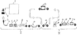
- the drawing schematically illustrates a process line for the manufacturing of a grain oriented electrical steel sheet according to the invention.
- the steel composition of the hot rolled band is defined in claim 1.
- the carbon level is closely reflected in the carbon level of the secondary recrystallized strip since the process dispenses with any deliberate intermediate decarburization annealing. For this reason it is of the utmost importance to control the carbon content during steelmaking such that the carbon content is less than 30 ppm (0.003 wt. %) in the melt to be cast.
- the inhibition to control the secondary recrystallization is mainly based on the precipitation of AlN. Accordingly, the content of Al and N should be controlled such that AlN is dissolved during slab reheating, precipitation is minimized or avoided during hot rolling but occur during the annealing of the strip performed at intermediate thickness.
- the contents of Als (acid soluble Al) and N are controlled such that the ratio Als/N is stoichiometric.
- the ratio Als/N is stoichiometric.
- ⁇ 35 % of the stoichiometric ratio or preferably within ⁇ 15 % of the stoichiometric ratio can be tolerated.
- the sulfur content should be maintained at a low level in order to avoid undue precipitation of MnS.
- the content should be less than 30 ppm, preferably less than 20 ppm and most preferred less than 10 ppm.
- the manganese content is maintained at 0.4 - 2 % in order to increase the resistivity of the alloy and thereby decreasing the core loss.
- the content of titanium should also be closely controlled since Ti is a strong nitride former. Ti enters the steel melt from the raw materials used in iron- and steelmaking. Accordingly, the ladle slag is normally to be skimmed after tapping and FeSi having a low Ti-content should be used.
- the content of Ti should be less than 0.006 % , preferably less than 0.004% or even less than 0.0020% (20 ppm).
- AlN In addition to AlN other inhibitors may be used to assist the control.
- Other possible elements that may be present are defined in claim 1. It may be noted that in some cases these elements are present as impurities. Cu and Sn may be added, typical in an amount of 0.1 %. As, Pb, P and Zn may be added as defined in claim 1. However, preferably, the total amount of these elements is less than 0.2%, in particular less than 0.05%. B, Ni, Cr, Te and Cd may be present as defined in claim 1. However, in most cases it is preferred that the total amount of these elements is restricted to 0.30%. Bismuth, when used, need to be present in an amount of at least 5 ppm in order to provide an effect. However, if the content is higher than 20 ppm brittleness problems may occur.
- reference numeral I represents a section for the provision of a steel alloy having the adequate chemical composition prepared for cold rolling, and of a hot rolled strip of the steel alloy according to a) and b) in the foregoing while reference numeral II represents a section for cold rolling of the hot rolled steel strip and for heat treatment of the strip in connection therewith according to c), d) and e) in the foregoing.
- molten steel is manufactured in a mode, which principles may be conventional per se, by means a complex of iron and steel manufacturing facilities which also may be conventional such as a number of the following ones: blast furnace, LD converter, electric arc furnace, VOD, RH degasser and others.
- any chosen combination of apparatuses for making molten steel is symbolically represented by complex 1 .
- the continuously cast strand 4 is successively cut to slabs 5 which are reheated in a walking beam furnace 6 to a temperature of between 1220 and 1300 °C, suitably to a temperature of about 1260 °C.
- a series of induction heating devices locally reheat the slabs eliminating any skid mark effect.
- each reheated slab 5 is subjected to roughing at > 1200 °C. in a roughing facility 7 in order to produce a plate or bar having a thickness of 20 - 80 mm.
- the plate or bar is hot rolled in a hot rolling mill 8 to form a strip 9 with a thickness of 1.5 - 4 mm, preferably 2 - 3 mm or 2 - 2.5 mm.
- the starting temperature of the hot rolling in the hot rolling mill 8 is > 920 °C, preferably 950 - 1200 °C, and most preferable 970 - 1150 °C, while the finish rolling temperature is > 850 °C.
- the hot rolled steel strip is cooled at a rate of 5 - 100 C/s down to a coiling temperature ⁇ 600 °C. and coiled at that temperature.
- the hot rolled strip is passed through a scale breaker (not shown), pickled in the pickling unit 10 and optionally annealed (not shown).
- pickling may be performed in sulphuric acid at a concentration of 235-245 g/l, which is regenerated by crystallization and centrifugation.
- the pickling time can be varied in the range 20 - 60 seconds. After pickling, the strip is trimmed and recoiled.
- the hot rolled strip is cold rolled in a cold rolling mill 12 to an intermediate thickness of 0.38 - 1.2 mm, preferably to 0.5 - 1.0 mm. Then, the cold rolled strip having said intermediate thickness is subjected to continuous intermediate annealing in a continuous type annealing furnace 13 at a temperature of 850 - 1000 °C, preferably at 880 - 930 °C, such that the cold rolled strip material is recrystallized.
- the atmosphere in the annealing furnace may be 100 % hydrogen or a mixture of hydrogen and nitrogen.
- the recrystallized strip is cooled and then cold rolled a second time in cold rolling mill 12 , now with a reduction rate of 40 - 70 % to a final thickness of 0.23 - 0.35 mm.
- the temperature of the strip is maintained in the range of 80 - 400 °C, preferably in the range of 100 - 200 °C.
- the cold rolled strip is now prepared to be annealed to provoke secondary recrystallization.
- the annealing is performed in two steps according to the invention.
- the final microstructure is obtained by secondary recrystallization annealing, which is incubated at low temperature in the batch annealing furnace and may subsequently be completed by the continuous annealing at high temperature, if not already completely recrystallized after batch annealing.
- the cold rolled and coiled strip 15 having said final thickness is batch annealed in a batch annealing furnace 16 by heating the strip at a rate of less than 200 C/h to a holding temperature of 860 - 950 °C. and holding the strip at that temperature for a period of time of 2 - 20 hours.
- the batch annealing is preferably performed in an atmosphere of dry hydrogen.
- an annealing separator in particular a MgO powder layer is built on the strip surface before entering the batch annealing furnace in order to prevent sticking.
- the atmosphere of the continuous intermediate annealing performed in a continuous type annealing furnace 13 contains water so that the water partial pressure and hydrogen partial pressure is in the range 0.1-0.7. Due to this presence of water an oxide layer, which is composed of Silica, Fayalite and Iron Oxide, adherent to the strip surface is built on the strip surface. During cold rolling such iron oxide remains adherent to the strip surface, and during box annealing react with MgO powder to form and adherent layer of forsterite, which act as a coating of the strip surface.
- MgO powder is not used during box annealing, oxidation during the continuous intermediate annealing, performed in a continuous type annealing furnace 13 , is detrimental and the presence of water during the annealing has to be avoided; in such a case the water partial pressure and hydrogen partial pressure has to be lower than 0.01.
- the cold rolled and batch annealed strip 17 is continuously annealed at a temperature of 800-1200 °C for 30 - 600 seconds in a continuous annealing furnace 18 in an atmosphere preferably consisting of dry hydrogen or dry hydrogen/nitrogen mixture.
- the continuous annealing mainly effects thermo-flattening and the temperature may be in the range of 800-950 °C.
- the secondary recrystallization is to be completed during this step, then it is better to perform the continuous annealing in the range of 950-1200 °C, preferably 1050-1150°C.
- the process further includes coating the continuously annealed sheet 19 with an organic or inorganic coating as an annealing separator, optionally with tensioning properties and curing the sheet for more than 20 seconds at a temperature exceeding 150 °C. in a continuous curing furnace 20 before coiling. Due to the invention as described in this patent specification and claims, the final product will have a maximum core loss at 1.7 T and 50 Hz (P 17/50 ) of ⁇ 2 W/kg and/or a magnetic polarization at 800 A/m (J 800 ) of > 1.7 T.
- the final annealing temperature may be optimized according to the starting rolling temperature.
- the starting finishing rolling temperature is ⁇ 1050°C then the final annealing as specified in point g) of claim 1 can be performed with a soaking temperature laying in the lower part of said range.
- the temperature could be in the range of 800-950 °C, preferably 860-950° because an annealing temperature above 950°C does not improve the final characteristics of the material but it increases the consumption of energy necessary to perform the annealing.
- the starting finishing rolling temperature is higher than 1050°C then the final annealing temperature specified in point g) of claim 1 should be the upper part of said.
- the temperature should in this case be in the range of 950°C-1200°C, preferably in the range of 1050°C-1150°C.
- the final annealing optimal temperature range varies depending on the starting rolling temperature is not completely clear but it would appear that when the starting rolling temperature is below 1050°C then the secondary recrystallization is virtually completed during the low temperature batch annealing. In this case, the final annealing is necessary only for performing thermo-flattening of the steel strip when the batch annealing is performed with the strip wound in a coil.
- a steel with a chemical composition as reported in Table 1 has been cast to form a slab, slab has been reheated at 1260 °C temperature, and hot rolled.
- a steel with a chemical composition as reported in Table 3 has been cast, slab have been treated at 1250 °C slab reheating temperature and hot rolled.
- a steel with a chemical composition as reported in Table 5 has been cast in 3 different slabs: a, b, c. Cast slabs have been reheated at A:1210 °C, B:1240 °C and C:1260 °C, and hot rolled.
- a steel with a chemical composition as reported in Table 9 has been cast in 2 different slabs: a, b. Cast slabs have been reheated at 1240 °C and hot rolled, after roughing, with two different starting finishing rolling temperature:
- Samples after hot rolling have been cold rolled down to 0,70 mm intermediate thickness.
- Samples at intermediate thickness have been annealed at 900°C for 100 sec.
- Annealed samples have been cold rolled down to final thickness of 0,30 mm and have been undergone to batch annealing with following cycle: heating from 25°C to 900°C in 6 h ; holding at 900°C for 10 h; cooling from 900°C to 25°C in 18 h.
Abstract
Description
- The present invention relates to a process for the production of grain oriented electrical steel, particularly grain oriented steel sheets to be used for cores in transformers and other electrical machines.
- Ever since the very beginning of the commercial use of alternating-current transformers and other alternating-current machinery, hysteresis and eddy current losses in the iron cores have been a problem. Very early it was found, however, that a low content of carbon and other impurities in the steels that were employed as a core material promoted a high permeability and a low coercive field intensity, i.e. reduced hysteresis losses. Further, it was recognized that a high content of silicon and possibly also aluminum in the steel could reduce the eddy current losses.
- A major technical achievement in this field was the invention of the cold rolled grain-oriented electrical steel by Norman P. Goss in the early thirties. The cold rolled grain-oriented electrical steel, often abbreviated CRGO, or called Goss- or GO-steel, is processed through a series of hot rolling, heat treatment, and cold rolling operations in a way aiming at achieving optimum properties in the rolling direction through control of the orientation of the crystals relative to the steel sheet. During the many years that have passed after the disclosure of Goss's invention, numerous modifications of the process have been suggested. Apart from the use of different combinations of inhibitors, it is also known to perform a decarburization of the cold rolled strip at final gauge through an annealing in wet atmosphere containing H2 (introduced by Carpenter with
US 2287467 ; see example of applications inEP 1 577 405 andEP 869 190 EP 0789093 ). - During decarburization annealing the carbon is oxidized at strip surface through the reaction with water contained in the annealing atmosphere and the strip is progressively decarburized by diffusion of carbon through the sheet thickness. Such decarburization requires several minutes to be completed and constitutes a relevant cost in the production process for the production of GO electrical steel.
- The "low heating rate" "high soaking temperature" batch annealing during which secondary recrystallization is performed, constitutes a high time-consumption and high cost in the known CRGO production process.
- Even if some improvements may have been achieved in terms of magnetic properties of the steel sheets, they have as a rule been gained at the cost of more complicated and hence less economic manufacturing facilities.
- It is the purpose of the present invention to provide a process for the manufacturing of grain oriented electrical steel sheets, i.e. a steel sheet with crystal grains predominantly in the so called Goss-orientation, which highly corresponds to the rolling direction of the steel sheet, but without provision of complicated manufacturing facilities or modes of operation which significantly raise the total manufacturing costs. Sheets in this context are defined as any flattened steel products that are thinner than a plate, including also strips regardless if the products are slit from wider sheets or not.
- Further, it is an objective of the invention that the final product in which the steel sheets manufactured according to the process of the invention are intended to be employed as core material has a maximum core loss at 1.7 T and 50 Hz (P17/50) of < 2 W/kg and/or a magnetic polarization at 800 A/m (J800) of > 1.7 T. The thickness of such sheets is typically in the range of 0.23 - 0.35 mm.
- These and other objectives can be achieved by a process for the manufacturing of a grain oriented electrical steel sheet comprising the steps of:
a) providing a hot rolled strip comprising in weight %:C < 0.006 preferably < 0.003 Si 3.0 - 3.5 preferably 3.1-3.3 Mn 0.4 - 2.0 preferably 0.45 - 0.65 Als 0.005-0.03 preferably 0.01-0.02 N 0.004 - 0.009 preferably 0.005 -0.008 S < 0.008 preferably < 0.005 Ti <0.006 preferably < 0.004 Cu 0.05 - 0.3 Sn 0.04 - 0.15 Ni < 0.1 preferably < 0.05 Cr < 0.2 preferably < 0.05 P < 0.02 preferably < 0.01 B < 0.01 preferably 0.001 - 0.005 Te < 0.01 preferably < 0.005 Cd < 0.01 preferably < 0.005 Zn < 0.01 preferably < 0.005 As < 0.01 preferably < 0.005 Pb < 0.01 preferably < 0.005 Bi < 0.002 preferably 0.0005 - 0.002
b) optionally annealing and/or pickling the hot rolled strip,
c) cold rolling the hot rolled strip to an intermediate thickness,
d) annealing the cold rolled strip in order to recrystallize the cold rolled strip,
e) cold rolling the recrystallized strip to a final thickness,
f) batch annealing the cold rolled strip having said final thickness, preferably by heating the strip at a rate of ≤ 200°C/h to a holding temperature within the range of 860 - 950 °C, and holding the strip at such a temperature for 2 - 20 h,
g) continuously annealing said batch annealed strip at a temperature of 800 - 1200 °C, preferably 1050 - 1150 °C, for a time of 30 - 600 s. - The new and efficient process results in a final product typically having a maximum core loss at 1.7 T at a sheet thickness of 0.30 mm and 50 Hz (P17/50) of < 2 W/kg and a magnetic polarization at 800 A/m (J800) of > 1.7 T.
- Key features of the inventive process includes the provision of a hot rolled strip having a carefully balance composition, in particular a very low carbon content. A decarburization annealing need not be performed during the transformation process of the hot rolled strip down to finished product.
- A further key feature is that the final annealing during which the secondary recrystallization happens is divided in two steps:
- the first step, performed in batch annealing, at a relatively low temperature (860°C-950°C) if compared to the high temperature at which the batch annealing for secondary recrystallization is performed in the state of art.
- the second step performed in continuous annealing at a temperature included in the range 800°C-1200°C, preferably 1050-1150 °C.
- This two step annealing allows the possibility of finalizing the recrystallization annealing in the continuous annealing line if not already completed during the batch annealing.
- The reason why it is advantageous to divide the final annealing in two steps is not yet completely clarified, but the inventors have hypothesized that, differently from what happens in the state of art cycle, the secondary recrystallization is onset during the batch annealing and may be completed in the continuous annealing line, if not already completed during batch annealing.
- The invention is defined in the claims.
- The drawing schematically illustrates a process line for the manufacturing of a grain oriented electrical steel sheet according to the invention.
- The steel composition of the hot rolled band is defined in claim 1. The carbon level is closely reflected in the carbon level of the secondary recrystallized strip since the process dispenses with any deliberate intermediate decarburization annealing. For this reason it is of the utmost importance to control the carbon content during steelmaking such that the carbon content is less than 30 ppm (0.003 wt. %) in the melt to be cast. The inhibition to control the secondary recrystallization is mainly based on the precipitation of AlN. Accordingly, the content of Al and N should be controlled such that AlN is dissolved during slab reheating, precipitation is minimized or avoided during hot rolling but occur during the annealing of the strip performed at intermediate thickness. For best result the contents of Als (acid soluble Al) and N are controlled such that the ratio Als/N is stoichiometric. However, from a practical point of view ± 35 % of the stoichiometric ratio or preferably within ± 15 % of the stoichiometric ratio can be tolerated.
- The sulfur content should be maintained at a low level in order to avoid undue precipitation of MnS. The content should be less than 30 ppm, preferably less than 20 ppm and most preferred less than 10 ppm. The manganese content is maintained at 0.4 - 2 % in order to increase the resistivity of the alloy and thereby decreasing the core loss.
- The content of titanium should also be closely controlled since Ti is a strong nitride former. Ti enters the steel melt from the raw materials used in iron- and steelmaking. Accordingly, the ladle slag is normally to be skimmed after tapping and FeSi having a low Ti-content should be used. The content of Ti should be less than 0.006 % , preferably less than 0.004% or even less than 0.0020% (20 ppm).
- In addition to AlN other inhibitors may be used to assist the control. Other possible elements that may be present are defined in claim 1. It may be noted that in some cases these elements are present as impurities. Cu and Sn may be added, typical in an amount of 0.1 %. As, Pb, P and Zn may be added as defined in claim 1. However, preferably, the total amount of these elements is less than 0.2%, in particular less than 0.05%. B, Ni, Cr, Te and Cd may be present as defined in claim 1. However, in most cases it is preferred that the total amount of these elements is restricted to 0.30%. Bismuth, when used, need to be present in an amount of at least 5 ppm in order to provide an effect. However, if the content is higher than 20 ppm brittleness problems may occur.
- In the drawing, reference numeral I represents a section for the provision of a steel alloy having the adequate chemical composition prepared for cold rolling, and of a hot rolled strip of the steel alloy according to a) and b) in the foregoing while reference numeral II represents a section for cold rolling of the hot rolled steel strip and for heat treatment of the strip in connection therewith according to c), d) and e) in the foregoing.
- In section I, molten steel is manufactured in a mode, which principles may be conventional per se, by means a complex of iron and steel manufacturing facilities which also may be conventional such as a number of the following ones: blast furnace, LD converter, electric arc furnace, VOD, RH degasser and others. In the drawing, any chosen combination of apparatuses for making molten steel is symbolically represented by complex 1. For the achievement of a steel having the following composition (in weight - %) adapted for electrical steel sheet production according to an aspect of the invention:
C 0.002 Si 3.2 Mn 0.5 S < 0.008 Als 0.01 - 0.02 N 0.006 Cu 0.1 Sn 0.1 - wherein the contents of Als (acid soluble aluminium) and N are such that the ratio Als/N is within ± 15 % of the stoichiometric ratio, balance iron and impurities,
- the following route may be followed
- Iron production in blast furnace and hot metal desulphurization. The sulphur content may be 40 - 60 ppm in the raw iron before the LD converter treatment.
- Treatment in LD converter to get aimed carbon content.
- Tapping into a ladle and performing ladle skimming.
- Ladle Furnace (LF) treatment to reheat steel before vacuum decarburization.
- Recirculation Degassing (RH Process), if necessary, in order to reduce the carbon content to the desired level and adjustment of the steel analysis.
- The molten steel is then sent to a
ladle furnace 2, where the steel composition is controlled and if necessary adjusted to comply with what is stated above and/or with the composition defined in the appending patent claims. For the manufacturing of a strip of steel from the molten steel with said proper composition, a number of methods can be contemplated, including any of the steps of ingot casting, continuous slab casting, thin slab casting or strip casting. Conveniently, however, molten steel with the proper composition is transferred to aconventional slab caster 3 from theladle furnace 2 for continuous slab casting. In this connection, the steel has to be adequately protected from contact with air to avoid N2 pick-up and oxidation of aluminum.
- The continuously cast strand 4 is successively cut to slabs 5 which are reheated in a walking beam furnace 6 to a temperature of between 1220 and 1300 °C, suitably to a temperature of about 1260 °C. On the transfer table, at furnace exit, a series of induction heating devices locally reheat the slabs eliminating any skid mark effect. Successively, each reheated slab 5 is subjected to roughing at > 1200 °C. in a roughing facility 7 in order to produce a plate or bar having a thickness of 20 - 80 mm. Next the plate or bar is hot rolled in a hot rolling mill 8 to form a strip 9 with a thickness of 1.5 - 4 mm, preferably 2 - 3 mm or 2 - 2.5 mm. The starting temperature of the hot rolling in the hot rolling mill 8 is > 920 °C, preferably 950 - 1200 °C, and most preferable 970 - 1150 °C, while the finish rolling temperature is > 850 °C. Before coiling, the hot rolled steel strip is cooled at a rate of 5 - 100 C/s down to a coiling temperature < 600 °C. and coiled at that temperature.
- Optionally, before cold rolling, the hot rolled strip is passed through a scale breaker (not shown), pickled in the
pickling unit 10 and optionally annealed (not shown). When employed, pickling may be performed in sulphuric acid at a concentration of 235-245 g/l, which is regenerated by crystallization and centrifugation. The pickling time can be varied in the range 20 - 60 seconds. After pickling, the strip is trimmed and recoiled. - Now, in section II, the hot rolled strip is cold rolled in a
cold rolling mill 12 to an intermediate thickness of 0.38 - 1.2 mm, preferably to 0.5 - 1.0 mm. Then, the cold rolled strip having said intermediate thickness is subjected to continuous intermediate annealing in a continuous type annealing furnace 13 at a temperature of 850 - 1000 °C, preferably at 880 - 930 °C, such that the cold rolled strip material is recrystallized. The atmosphere in the annealing furnace may be 100 % hydrogen or a mixture of hydrogen and nitrogen. Next, the recrystallized strip is cooled and then cold rolled a second time incold rolling mill 12, now with a reduction rate of 40 - 70 % to a final thickness of 0.23 - 0.35 mm. During one or both of the cold rolling operations, the temperature of the strip is maintained in the range of 80 - 400 °C, preferably in the range of 100 - 200 °C. - The cold rolled strip is now prepared to be annealed to provoke secondary recrystallization. The annealing is performed in two steps according to the invention. The final microstructure is obtained by secondary recrystallization annealing, which is incubated at low temperature in the batch annealing furnace and may subsequently be completed by the continuous annealing at high temperature, if not already completely recrystallized after batch annealing. In a first step, the cold rolled and coiled strip 15 having said final thickness is batch annealed in a batch annealing furnace 16 by heating the strip at a rate of less than 200 C/h to a holding temperature of 860 - 950 °C. and holding the strip at that temperature for a period of time of 2 - 20 hours. The batch annealing is preferably performed in an atmosphere of dry hydrogen. In another preferred embodiment an annealing separator, in particular a MgO powder layer is built on the strip surface before entering the batch annealing furnace in order to prevent sticking. In the framework of this preferred embodiment it is useful if the atmosphere of the continuous intermediate annealing performed in a continuous type annealing furnace 13 contains water so that the water partial pressure and hydrogen partial pressure is in the range 0.1-0.7. Due to this presence of water an oxide layer, which is composed of Silica, Fayalite and Iron Oxide, adherent to the strip surface is built on the strip surface. During cold rolling such iron oxide remains adherent to the strip surface, and during box annealing react with MgO powder to form and adherent layer of forsterite, which act as a coating of the strip surface.
- If MgO powder is not used during box annealing, oxidation during the continuous intermediate annealing, performed in a continuous type annealing furnace 13, is detrimental and the presence of water during the annealing has to be avoided; in such a case the water partial pressure and hydrogen partial pressure has to be lower than 0.01.
- Subsequent to batch annealing in furnace 16, the cold rolled and batch annealed
strip 17 is continuously annealed at a temperature of 800-1200 °C for 30 - 600 seconds in acontinuous annealing furnace 18 in an atmosphere preferably consisting of dry hydrogen or dry hydrogen/nitrogen mixture. If the secondary recrystallization is completed after the batch annealing, then the continuous annealing mainly effects thermo-flattening and the temperature may be in the range of 800-950 °C. On the other hand, if the secondary recrystallization is to be completed during this step, then it is better to perform the continuous annealing in the range of 950-1200 °C, preferably 1050-1150°C. - Finally, the process, according to the preferred embodiment, further includes coating the continuously annealed
sheet 19 with an organic or inorganic coating as an annealing separator, optionally with tensioning properties and curing the sheet for more than 20 seconds at a temperature exceeding 150 °C. in acontinuous curing furnace 20 before coiling. Due to the invention as described in this patent specification and claims, the final product will have a maximum core loss at 1.7 T and 50 Hz (P17/50) of < 2 W/kg and/or a magnetic polarization at 800 A/m (J800) of > 1.7 T. - In a second embodiment of the present invention it has been found that the final annealing temperature may be optimized according to the starting rolling temperature. In particular, it has been found that if the starting finishing rolling temperature is ≤ 1050°C then the final annealing as specified in point g) of claim 1 can be performed with a soaking temperature laying in the lower part of said range. The temperature could be in the range of 800-950 °C, preferably 860-950° because an annealing temperature above 950°C does not improve the final characteristics of the material but it increases the consumption of energy necessary to perform the annealing.
- In a further embodiment of the present invention it has instead found that if the starting finishing rolling temperature is higher than 1050°C then the final annealing temperature specified in point g) of claim 1 should be the upper part of said. The temperature should in this case be in the range of 950°C-1200°C, preferably in the range of 1050°C-1150°C.
- The reason why the final annealing optimal temperature range varies depending on the starting rolling temperature is not completely clear but it would appear that when the starting rolling temperature is below 1050°C then the secondary recrystallization is virtually completed during the low temperature batch annealing. In this case, the final annealing is necessary only for performing thermo-flattening of the steel strip when the batch annealing is performed with the strip wound in a coil.
- In case instead the starting rolling temperature falls above 1050 °C the secondary recrystallization after low temperature batch annealing is not complete and an high temperature final annealing is necessary to complete the secondary recrystallization.
- A steel with a chemical composition as reported in Table 1 has been cast to form a slab, slab has been reheated at 1260 °C temperature, and hot rolled.
- Samples after hot rolling have been cold rolled down to 0,70 mm intermediate thickness.
- Samples at intermediate thickness have been annealed at 900 °C for 100 sec.
- Annealed samples have been cold rolled down to final thickness of 0,30 mm.
- Cold rolled samples at final thickness have been subjected to batch annealing with the following cycle:
- Heating from 25°C to 900 °C in 12 h; holding at 900 °C for 10 h; cooling from 900 °C to 25°C in 18 h.
- Batch annealed samples have been annealed at 1100 °C for 180 sec.
- A steel with a chemical composition as reported in Table 3 has been cast, slab have been treated at 1250 °C slab reheating temperature and hot rolled.
- Samples after hot rolling have been cold rolled down to 0,70 mm intermediate thickness.
- Samples at intermediate thickness have been annealed at 900°C for 100 sec.
- Annealed samples have been cold rolled down to final thickness of 0,30 mm.
- Cold rolled samples at final thickness have been subjected to batch annealing with the following cycle:
- Heating from 25°C to 900 °C in12 h; holding at 900 °C for 10 h; cooling from 900 °C to 25 °C in 18 h.
- Batch annealed samples have been annealed at 1100 °C for 60 sec and 180 sec.
Magnetic characteristic measured after final annealing have been reported in Table 4. - A steel with a chemical composition as reported in Table 5 has been cast in 3 different slabs: a, b, c. Cast slabs have been reheated at A:1210 °C, B:1240 °C and C:1260 °C, and hot rolled.
- Samples after hot rolling have been cold rolled down to 0,70 mm intermediate thickness.
- Samples at intermediate thickness have been annealed at 900°C for 100 sec.
- Annealed samples have been cold rolled down to final thickness of 0,30 mm.
- Cold rolled samples at final thickness have been separated in two groups of samples subjected to batch annealing with two different cycles:
- Cycle I: Heating from 25°C to 900°C in 6 h ; holding at 900°C for 10 h;
- cooling from 900°C to 25°C in 18 h
- Cycle II: Heating from 25°C to 880°C in 6 h ; holding at 880°C for 10 h;
- cooling from 880°C to 25°C in 18 h.
- Batch annealed samples have been annealed at 1100°C for 180 sec.
Magnetic characteristic measured after final annealing have been reported in Table 6. - Steel with chemical composition as reported in Table 7 has been cast, cast slab have been treated at 1270 °C slab reheating temperature, and hot rolled.
- Samples after hot rolling have been cold rolled down to 0,70 mm intermediate thickness.
- Samples at intermediate thickness have been annealed at 900 °C for 100 sec.
- Annealed samples have been cold rolled down to final thickness of 0,30 mm.
- Cold rolled samples at final thickness have been separated in two groups of samples subjected to batch annealing with two different following cycles:
- Cycle III: Heating from 25 °C to 850 °C in 6 h ; holding at 850 °C for 10 h; cooling from 850 °C to 25 °C in 18 h (condition out of the invention) Cycle IV: Heating from 25 °C to 900 °C in 6 h ; holding at 900 °C for 10 h; cooling from 900 °C to 25 °C in 18 h.
- Batch annealed samples have been annealed at 1100 °C for 180 sec.
Magnetic characteristic measured after final annealing have been reported in Table 8 - A steel with a chemical composition as reported in Table 9 has been cast in 2 different slabs: a, b. Cast slabs have been reheated at 1240 °C and hot rolled, after roughing, with two different starting finishing rolling temperature:
- slabs a, b, had a starting finishing rolling temperature of 1140°C,
- slabs c, d, had a starting finishing rolling temperature of 980°C.
- Samples after hot rolling have been cold rolled down to 0,70 mm intermediate thickness.
- Samples at intermediate thickness have been annealed at 900°C for 100 sec.
- Annealed samples have been cold rolled down to final thickness of 0,30 mm and have been undergone to batch annealing with following cycle: heating from 25°C to 900°C in 6 h ; holding at 900°C for 10 h; cooling from 900°C to 25°C in 18 h.
- Batch annealed samples have been separated in two groups of samples subjected to final annealing with two different following cycles:
- Cycle (i): 1100°C for 180 sec.
- Cycle (ii): 850°C for 180 sec.
- Magnetic characteristic measured after final annealing have been reported in Table 10.
| EX. | Chemical Analysis | ||||||||
| Fe | Sn | Al sol | C | N | Cu | Si | Mn | S | |
| A | Bal | 0.110 | 0.0150 | 0. 0033 | 0.0075 | 0.12 | 3.15 | 0.49 | 0.0036 |
| P17 | J800 | |
| [W/kg] | [mT] | |
| A | 1,79 | 1740 |
| EX. | Chemical Analysis | ||||||||
| Fe | Sn | Al sol | C | N | Cu | Si | Mn | S | |
| B | Bal | 0.100 | 0.0149 | 0.004 | 0. 0061 | 0.12 | 3.14 | 0.50 | 0.002 |
| Final annealing time | P17 | J800 |
| [W/kg] | [mT] | |
| 60 sec | 1,82 | 1720 |
| 180 sec | 1,81 | 1710 |
| EX. | Chemical Analysis | ||||||||
| Fe | Sn | Alsol | C | N | Cu | Si | Mn | S | |
| C | Bal | 0.100 | 0.0098 | 0.003 | 0.0042 | 0.12 | 3.14 | 0.50 | 0. 0023 |
| Batch annealing cycle I | Batch annealing cycle II | ||||
| Slab | P17 | J800 | P17 | J800 | |
| RH T | [W/kg] | [mT] | [W/kg] | [mT] | |
| Slab a | 1210°C | 1,89 | 1695 | 1,78 | 1695 |
| Slab b | 1240°C | 1,80 | 1710 | 1,68 | 1745 |
| Slab c | 1260°C | 1,65 | 1747 | 1,71 | 1730 |
| EX. | Chemical Analysis | ||||||||
| Fe | Sn | Al sol | C | N | Cu | Si | Mn | S | |
| D | Bal | 0.100 | 0.012 | 0.003 | 0.0048 | 0.12 | 3.10 | 0.50 | 0.0023 |
| Batch annealing cycle IV | Batch annealing cycle III (out of the invention limit) | ||
| P17 | J800 | P17 | J800 |
| [W/kg] | [mT] | [W/kg] | [mT] |
| 1,82 | 1720 | 2,18 | 1608 |
| EX. | Chemical Analysis | ||||||||
| Fe | Sn | Al sol | C | N | Cu | Si | Mn | S | |
| E | Bal | 0.100 | 0.0149 | 0.004 | 0. 0061 | 0.12 | 3.14 | 0.50 | 0.002 |
| Final annealing cycle (i) | Final annealing cycle (ii) | |||||
| 1100°C 180 s | 850°C 180 s | |||||
| Slab RH T [°C] | Start. Fin. Roll. Temp. [°C] | P17 [W/kg] | J800 [mT] | P17 [W/kg] | J800 [mT] | |
| Slab a | 1240 | 1140 | 1,75 | 1740 | 1,80 | 1720 |
| Slab b | 1240 | 980 | 1,85 | 1720 | 1,60 | 1720 |
Claims (15)
- A process for the production of a grain oriented electrical steel sheet comprising the steps of:a) providing a hot rolled strip comprising in weight %:
C < 0.006 preferably < 0.003 Si 3.0 - 3.5 preferably 3.1-3.3 Mn 0.4 - 2.0 preferably 0.45 - 0.65 Als 0.005-0.03 preferably 0.01-0.02 N 0.004 - 0.009 preferably 0.005 -0.008 S < 0.008 preferably < 0.005 Ti <0.006 preferably < 0.004 Cu 0.05 - 0.3 Sn 0.04 - 0.15 Ni < 0.1 preferably < 0.05 Cr < 0.2 preferably < 0.05 P < 0.02 preferably < 0.01 B < 0.01 preferably 0.001 - 0.005 Te < 0.01 preferably < 0.005 Cd < 0.01 preferably < 0.005 Zn < 0.01 preferably < 0.005 As < 0.01 preferably < 0.005 Pb < 0.01 preferably < 0.005 Bi < 0.002 preferably 0.0005 - 0.002 b) optionally annealing and/or pickling the hot rolled strip,c) cold rolling the hot rolled strip to an intermediate thickness,d) annealing the cold rolled strip in order to recrystallize the cold rolled strip,e) cold rolling the recrystallized strip to a final thickness,f) batch annealing the cold rolled strip having said final thickness, preferably by heating the strip at a rate of ≤ 200°C/h to a holding temperature within the range 860 - 950 °C, and holding the strip at such temperature for 2 - 20 h,g) continuously annealing said batch annealed strip at a temperature of 800 - 1200 °C, for a time of 30 - 600 s. - A process according to claim 1, wherein the intermediate thickness of the strip in step c) is 0.38 - 1.2 mm, preferably 0.5 - 1.0 mm.
- A process according to claim 1 or 2, wherein the strip in step e) is cold rolled with a reduction rate of 40 - 70% to a final thickness of 0.23 - 0.35 mm.
- A process according to any of the preceding claims, wherein the annealing temperature in step d) is 850 - 1000 °C, preferably 880 - 930 °C.
- A process according to any of the preceding claims, wherein the composition of the hot rolled strip fulfils at least one of the following requirements:
C < 0.003 preferably < 0.002 Si 3.0 - 3.5 preferably 3.1-3.3 Mn 0.4 - 1.0 preferably 0.45 - 0.65 ls 0.012-0.017 preferably 0.014 - 0.016 N 0.005 - 0.008 preferably 0.006 - 0.007 S < 0.003 preferably < 0.002 Ti < 0.004 preferably < 0.002 Cu 0.08 - 0.12 Sn 0.08 - 0.12 Ni < 0.04 preferably < 0.01 Cr < 0.04 preferably < 0.01 P < 0.015 preferably < 0.01 B < 0.005 preferably 0.001 - 0.002 Te < 0.01 preferably < 0.005 Cd < 0.01 preferably < 0.005 Zn < 0.01 preferably < 0.005 As < 0.01 preferably < 0.005 Pb < 0.01 preferably < 0.005 Bi < 0.002 preferably 0.0005 - 0.002 - A process according to any of the preceding claims, wherein the temperature of the strip during one or both of the cold rolling steps c) and e) respectively, is maintained in the range of 80 - 400 °C, preferably 100 - 200 °C.
- A process according to any of the preceding claims, wherein the step of providing the hot rolled strip includes any of the steps of ingot casting, continuous slab casting, thin slab casting or strip casting.
- A process according to any of the preceding claims, wherein the step a) of providing a hot rolled strip includes one or more of the steps of continuously casting a slab, reheating the slab to a T>1220°C, roughing the slab at > 1100 °C in order to produce a bar having a thickness 20 - 80 mm and hot rolling the bar to produce the hot rolled strip.
- A process according to claim 8, wherein the starting temperature of the hot rolling is > 920 °C, preferably 950 -1200 °C most preferable 970°C- 1150 °C and wherein the finish rolling temperature is > 850 °C.
- A process according to claim 9 wherein the starting temperature of the hot rolling is lower than 1050°C and/or the continuously annealing specified in point g) of claim 1 is performed at a temperature in the range 800-950 °C.
- A process according to claim 9 wherein the starting temperature of the hot rolling is greater than 1050°C and/or the continuously annealing specified in point g) of claim 1 is in the range 950-1200°C and preferably in the range 1050-1150 °C.
- A process according to any of the claims 8, 9, 10 or 11 wherein the hot rolled steel sheet is cooled at a rate of 5 -100 °C/s down to coiling temperature of < 600 °C and coiled at said temperature.
- A process according to any of the preceding claims, wherein the hot rolled strip has a thickness of 1.5 - 4 mm, preferably 2 - 3 mm.
- A process according to any of the preceding claims, wherein the contents of Als and N are controlled such that the ratio Als/N is within ± 35 % of the stoichiometric ratio, preferably within ± 15 % of the stoichiometric ratio.
- A process according to any of the preceding claims, wherein the process further includes at least one of the steps of: coating the continuously annealed strip obtained in step g) with an organic or inorganic coating as an annealing separator, optionally with tensioning properties and curing at >150 °C for > 20s.
Priority Applications (1)
| Application Number | Priority Date | Filing Date | Title |
|---|---|---|---|
| EP13158409.6A EP2775007B1 (en) | 2013-03-08 | 2013-03-08 | A process for the production of a grain-oriented electrical steel |
Applications Claiming Priority (1)
| Application Number | Priority Date | Filing Date | Title |
|---|---|---|---|
| EP13158409.6A EP2775007B1 (en) | 2013-03-08 | 2013-03-08 | A process for the production of a grain-oriented electrical steel |
Publications (2)
| Publication Number | Publication Date |
|---|---|
| EP2775007A1 true EP2775007A1 (en) | 2014-09-10 |
| EP2775007B1 EP2775007B1 (en) | 2018-12-05 |
Family
ID=47843143
Family Applications (1)
| Application Number | Title | Priority Date | Filing Date |
|---|---|---|---|
| EP13158409.6A Not-in-force EP2775007B1 (en) | 2013-03-08 | 2013-03-08 | A process for the production of a grain-oriented electrical steel |
Country Status (1)
| Country | Link |
|---|---|
| EP (1) | EP2775007B1 (en) |
Cited By (8)
| Publication number | Priority date | Publication date | Assignee | Title |
|---|---|---|---|---|
| WO2016035530A1 (en) * | 2014-09-01 | 2016-03-10 | 新日鐵住金株式会社 | Grain-oriented electromagnetic steel sheet |
| CN106298221A (en) * | 2016-08-30 | 2017-01-04 | 河南中岳非晶新型材料股份有限公司 | Noncrystal anti-DC iron core and heat treatment method thereof |
| WO2017073615A1 (en) * | 2015-10-26 | 2017-05-04 | 新日鐵住金株式会社 | Grain-oriented electromagnetic steel sheet and decarburized steel sheet used for producing same |
| CN108277429A (en) * | 2017-01-05 | 2018-07-13 | 鞍钢股份有限公司 | A kind of production method of high-silicon electrical steel |
| US20190032168A1 (en) * | 2017-07-25 | 2019-01-31 | Hyundai Motor Company | Continuous annealing apparatus |
| JP2019019358A (en) * | 2017-07-13 | 2019-02-07 | 新日鐵住金株式会社 | Grain-oriented electromagnetic steel sheet excellent in coating adhesion and method for manufacturing the same |
| JP2019019359A (en) * | 2017-07-13 | 2019-02-07 | 新日鐵住金株式会社 | Grain-oriented electromagnetic steel sheet excellent in coating adhesion and method for manufacturing the same |
| JP2019505671A (en) * | 2015-12-21 | 2019-02-28 | ポスコPosco | Oriented electrical steel sheet and manufacturing method thereof |
Citations (11)
| Publication number | Priority date | Publication date | Assignee | Title |
|---|---|---|---|---|
| US2287467A (en) | 1940-01-03 | 1942-06-23 | American Rolling Mill Co | Process of producing silicon steel |
| JPH08134542A (en) * | 1994-11-08 | 1996-05-28 | Sumitomo Metal Ind Ltd | Production of grain oriented silicon steel sheet having excellent blanking property |
| EP0789093A1 (en) | 1994-11-16 | 1997-08-13 | Nippon Steel Corporation | Process for producing directional electrical sheet excellent in glass coating and magnetic properties |
| EP0869190A1 (en) | 1997-03-26 | 1998-10-07 | Kawasaki Steel Corporation | Grain oriented electrical steel sheet having very low iron loss and production for same |
| JPH10273725A (en) * | 1997-03-31 | 1998-10-13 | Sumitomo Metal Ind Ltd | Manufacture of grain oriented silicon steel sheet |
| EP0997540A1 (en) * | 1998-10-27 | 2000-05-03 | Kawasaki Steel Corporation | Electromagnetic steel sheet and process for producing the same |
| EP1004680A1 (en) * | 1998-10-09 | 2000-05-31 | Kawasaki Steel Corporation | Method of making grain-oriented magnetic steel sheet having low iron loss |
| JP2001107147A (en) * | 1999-10-12 | 2001-04-17 | Kawasaki Steel Corp | Method for producing grain-oriented silicons steel sheet |
| EP1279747A2 (en) * | 2001-07-24 | 2003-01-29 | Kawasaki Steel Corporation | A method of manufacturing grain-oriented electrical steel sheets |
| EP1577405A1 (en) | 2002-10-29 | 2005-09-21 | JFE Steel Corporation | Method for producing grain oriented magnetic steel sheet and grain oriented magnetic steel sheet |
| JP2009228118A (en) * | 2008-03-25 | 2009-10-08 | Jfe Steel Corp | Method for manufacturing grain-oriented electrical steel sheet |
-
2013
- 2013-03-08 EP EP13158409.6A patent/EP2775007B1/en not_active Not-in-force
Patent Citations (12)
| Publication number | Priority date | Publication date | Assignee | Title |
|---|---|---|---|---|
| US2287467A (en) | 1940-01-03 | 1942-06-23 | American Rolling Mill Co | Process of producing silicon steel |
| JPH08134542A (en) * | 1994-11-08 | 1996-05-28 | Sumitomo Metal Ind Ltd | Production of grain oriented silicon steel sheet having excellent blanking property |
| EP0789093A1 (en) | 1994-11-16 | 1997-08-13 | Nippon Steel Corporation | Process for producing directional electrical sheet excellent in glass coating and magnetic properties |
| US5840131A (en) * | 1994-11-16 | 1998-11-24 | Nippon Steel Corporation | Process for producing grain-oriented electrical steel sheet having excellent glass film and magnetic properties |
| EP0869190A1 (en) | 1997-03-26 | 1998-10-07 | Kawasaki Steel Corporation | Grain oriented electrical steel sheet having very low iron loss and production for same |
| JPH10273725A (en) * | 1997-03-31 | 1998-10-13 | Sumitomo Metal Ind Ltd | Manufacture of grain oriented silicon steel sheet |
| EP1004680A1 (en) * | 1998-10-09 | 2000-05-31 | Kawasaki Steel Corporation | Method of making grain-oriented magnetic steel sheet having low iron loss |
| EP0997540A1 (en) * | 1998-10-27 | 2000-05-03 | Kawasaki Steel Corporation | Electromagnetic steel sheet and process for producing the same |
| JP2001107147A (en) * | 1999-10-12 | 2001-04-17 | Kawasaki Steel Corp | Method for producing grain-oriented silicons steel sheet |
| EP1279747A2 (en) * | 2001-07-24 | 2003-01-29 | Kawasaki Steel Corporation | A method of manufacturing grain-oriented electrical steel sheets |
| EP1577405A1 (en) | 2002-10-29 | 2005-09-21 | JFE Steel Corporation | Method for producing grain oriented magnetic steel sheet and grain oriented magnetic steel sheet |
| JP2009228118A (en) * | 2008-03-25 | 2009-10-08 | Jfe Steel Corp | Method for manufacturing grain-oriented electrical steel sheet |
Cited By (16)
| Publication number | Priority date | Publication date | Assignee | Title |
|---|---|---|---|---|
| WO2016035530A1 (en) * | 2014-09-01 | 2016-03-10 | 新日鐵住金株式会社 | Grain-oriented electromagnetic steel sheet |
| US11377705B2 (en) | 2014-09-01 | 2022-07-05 | Nippon Steel Corporation | Grain-oriented electrical steel sheet |
| US10604818B2 (en) | 2014-09-01 | 2020-03-31 | Nippon Steel Corporation | Grain-oriented electrical steel sheet |
| CN108138291A (en) * | 2015-10-26 | 2018-06-08 | 新日铁住金株式会社 | Grain-oriented magnetic steel sheet and the decarburization steel plate for its manufacture |
| JPWO2017073615A1 (en) * | 2015-10-26 | 2018-08-16 | 新日鐵住金株式会社 | Oriented electrical steel sheet and decarburized steel sheet used for manufacturing the same |
| WO2017073615A1 (en) * | 2015-10-26 | 2017-05-04 | 新日鐵住金株式会社 | Grain-oriented electromagnetic steel sheet and decarburized steel sheet used for producing same |
| CN108138291B (en) * | 2015-10-26 | 2020-06-05 | 日本制铁株式会社 | Grain-oriented electromagnetic steel sheet and decarburized steel sheet for production thereof |
| US10907234B2 (en) | 2015-10-26 | 2021-02-02 | Nippon Steel Corporation | Grain-oriented electrical steel sheet and decarburized steel sheet used for manufacturing the same |
| JP2019505671A (en) * | 2015-12-21 | 2019-02-28 | ポスコPosco | Oriented electrical steel sheet and manufacturing method thereof |
| CN106298221B (en) * | 2016-08-30 | 2018-01-30 | 河南中岳非晶新型材料股份有限公司 | Noncrystal anti-DC iron core and its heat treatment method |
| CN106298221A (en) * | 2016-08-30 | 2017-01-04 | 河南中岳非晶新型材料股份有限公司 | Noncrystal anti-DC iron core and heat treatment method thereof |
| CN108277429A (en) * | 2017-01-05 | 2018-07-13 | 鞍钢股份有限公司 | A kind of production method of high-silicon electrical steel |
| JP2019019358A (en) * | 2017-07-13 | 2019-02-07 | 新日鐵住金株式会社 | Grain-oriented electromagnetic steel sheet excellent in coating adhesion and method for manufacturing the same |
| JP2019019359A (en) * | 2017-07-13 | 2019-02-07 | 新日鐵住金株式会社 | Grain-oriented electromagnetic steel sheet excellent in coating adhesion and method for manufacturing the same |
| US20190032168A1 (en) * | 2017-07-25 | 2019-01-31 | Hyundai Motor Company | Continuous annealing apparatus |
| US10597749B2 (en) * | 2017-07-25 | 2020-03-24 | Hyundai Motor Company | Continuous annealing apparatus |
Also Published As
| Publication number | Publication date |
|---|---|
| EP2775007B1 (en) | 2018-12-05 |
Similar Documents
| Publication | Publication Date | Title |
|---|---|---|
| EP2775007B1 (en) | A process for the production of a grain-oriented electrical steel | |
| JP6844125B2 (en) | Manufacturing method of grain-oriented electrical steel sheet | |
| US5643370A (en) | Grain oriented electrical steel having high volume resistivity and method for producing same | |
| EP2470679B1 (en) | Process to manufacture grain-oriented electrical steel strip | |
| EP2876173B1 (en) | Manufacturing method of electrical steel sheet grain-oriented | |
| RU2391416C1 (en) | Method of production of texturised electrical steel sheet with high magnetic flux density | |
| KR101975685B1 (en) | Grain-oriented electromagnetic steel sheet | |
| KR20150033740A (en) | Method of production of grain-oriented silicon steel sheet grain oriented electrical steel sheet and use thereof | |
| JP7312249B2 (en) | Bidirectional electrical steel sheet and manufacturing method thereof | |
| CN105274427A (en) | High-magnetic-induction oriented silicon steel and production method | |
| JPH0686631B2 (en) | Method for manufacturing unidirectional electrical steel sheet with high magnetic flux density | |
| JPH05140648A (en) | Manufacture of now-oriented silicon steel sheet having high magnetic flux density and low core loss | |
| JPH059580A (en) | Production of grain-oriented silicon steel sheet extremely excellent in magnetic property | |
| KR20190078238A (en) | Non-oriented electrical steel sheet and method for manufacturing the same | |
| KR950009760B1 (en) | Method of manufacturing grain oriented silicon steel sheet | |
| US5425820A (en) | Oriented magnetic steel sheets and manufacturing process therefor | |
| KR950002895B1 (en) | Ultrahigh-silicon directional electrical steel sheet and production thereof | |
| JPH0949023A (en) | Production of grain oriented silicon steel sheet excellent in iron loss | |
| GB2060697A (en) | Grain-oriented silicon steel production | |
| JPH0419297B2 (en) | ||
| KR102319831B1 (en) | Method of grain oriented electrical steel sheet | |
| KR950014313B1 (en) | Method of producing grain-oriented silicon steel with small boron addition | |
| JP4261633B2 (en) | Manufacturing method of unidirectional electrical steel sheet | |
| JP2023507437A (en) | Bidirectional electrical steel sheet and manufacturing method thereof | |
| JP3232148B2 (en) | Manufacturing method of grain-oriented electrical steel sheet with excellent magnetic properties |
Legal Events
| Date | Code | Title | Description |
|---|---|---|---|
| PUAI | Public reference made under article 153(3) epc to a published international application that has entered the european phase |
Free format text: ORIGINAL CODE: 0009012 |
|
| 17P | Request for examination filed |
Effective date: 20130308 |
|
| AK | Designated contracting states |
Kind code of ref document: A1 Designated state(s): AL AT BE BG CH CY CZ DE DK EE ES FI FR GB GR HR HU IE IS IT LI LT LU LV MC MK MT NL NO PL PT RO RS SE SI SK SM TR |
|
| AX | Request for extension of the european patent |
Extension state: BA ME |
|
| R17P | Request for examination filed (corrected) |
Effective date: 20141209 |
|
| RBV | Designated contracting states (corrected) |
Designated state(s): AL AT BE BG CH CY CZ DE DK EE ES FI FR GB GR HR HU IE IS IT LI LT LU LV MC MK MT NL NO PL PT RO RS SE SI SK SM TR |
|
| 17Q | First examination report despatched |
Effective date: 20150202 |
|
| STAA | Information on the status of an ep patent application or granted ep patent |
Free format text: STATUS: EXAMINATION IS IN PROGRESS |
|
| REG | Reference to a national code |
Ref country code: DE Ref legal event code: R079 Ref document number: 602013047671 Country of ref document: DE Free format text: PREVIOUS MAIN CLASS: C22C0038020000 Ipc: C22C0038000000 |
|
| GRAP | Despatch of communication of intention to grant a patent |
Free format text: ORIGINAL CODE: EPIDOSNIGR1 |
|
| STAA | Information on the status of an ep patent application or granted ep patent |
Free format text: STATUS: GRANT OF PATENT IS INTENDED |
|
| RIC1 | Information provided on ipc code assigned before grant |
Ipc: C22C 38/06 20060101ALI20180628BHEP Ipc: C22C 38/02 20060101ALI20180628BHEP Ipc: C21D 8/12 20060101ALI20180628BHEP Ipc: C22C 38/00 20060101AFI20180628BHEP Ipc: C21D 9/46 20060101ALI20180628BHEP Ipc: C22C 38/16 20060101ALI20180628BHEP Ipc: C22C 38/04 20060101ALI20180628BHEP |
|
| INTG | Intention to grant announced |
Effective date: 20180725 |
|
| GRAS | Grant fee paid |
Free format text: ORIGINAL CODE: EPIDOSNIGR3 |
|
| GRAA | (expected) grant |
Free format text: ORIGINAL CODE: 0009210 |
|
| GRAA | (expected) grant |
Free format text: ORIGINAL CODE: 0009210 |
|
| STAA | Information on the status of an ep patent application or granted ep patent |
Free format text: STATUS: THE PATENT HAS BEEN GRANTED |
|
| AK | Designated contracting states |
Kind code of ref document: B1 Designated state(s): AL AT BE BG CH CY CZ DE DK EE ES FI FR GB GR HR HU IE IS IT LI LT LU LV MC MK MT NL NO PL PT RO RS SE SI SK SM TR |
|
| REG | Reference to a national code |
Ref country code: GB Ref legal event code: FG4D |
|
| REG | Reference to a national code |
Ref country code: CH Ref legal event code: EP |
|
| REG | Reference to a national code |
Ref country code: AT Ref legal event code: REF Ref document number: 1073149 Country of ref document: AT Kind code of ref document: T Effective date: 20181215 |
|
| REG | Reference to a national code |
Ref country code: IE Ref legal event code: FG4D |
|
| REG | Reference to a national code |
Ref country code: DE Ref legal event code: R096 Ref document number: 602013047671 Country of ref document: DE |
|
| REG | Reference to a national code |
Ref country code: NL Ref legal event code: FP |
|
| REG | Reference to a national code |
Ref country code: SE Ref legal event code: TRGR |
|
| REG | Reference to a national code |
Ref country code: AT Ref legal event code: MK05 Ref document number: 1073149 Country of ref document: AT Kind code of ref document: T Effective date: 20181205 |
|
| REG | Reference to a national code |
Ref country code: LT Ref legal event code: MG4D |
|
| PG25 | Lapsed in a contracting state [announced via postgrant information from national office to epo] |
Ref country code: ES Free format text: LAPSE BECAUSE OF FAILURE TO SUBMIT A TRANSLATION OF THE DESCRIPTION OR TO PAY THE FEE WITHIN THE PRESCRIBED TIME-LIMIT Effective date: 20181205 Ref country code: LT Free format text: LAPSE BECAUSE OF FAILURE TO SUBMIT A TRANSLATION OF THE DESCRIPTION OR TO PAY THE FEE WITHIN THE PRESCRIBED TIME-LIMIT Effective date: 20181205 Ref country code: NO Free format text: LAPSE BECAUSE OF FAILURE TO SUBMIT A TRANSLATION OF THE DESCRIPTION OR TO PAY THE FEE WITHIN THE PRESCRIBED TIME-LIMIT Effective date: 20190305 Ref country code: AT Free format text: LAPSE BECAUSE OF FAILURE TO SUBMIT A TRANSLATION OF THE DESCRIPTION OR TO PAY THE FEE WITHIN THE PRESCRIBED TIME-LIMIT Effective date: 20181205 Ref country code: BG Free format text: LAPSE BECAUSE OF FAILURE TO SUBMIT A TRANSLATION OF THE DESCRIPTION OR TO PAY THE FEE WITHIN THE PRESCRIBED TIME-LIMIT Effective date: 20190305 Ref country code: HR Free format text: LAPSE BECAUSE OF FAILURE TO SUBMIT A TRANSLATION OF THE DESCRIPTION OR TO PAY THE FEE WITHIN THE PRESCRIBED TIME-LIMIT Effective date: 20181205 Ref country code: LV Free format text: LAPSE BECAUSE OF FAILURE TO SUBMIT A TRANSLATION OF THE DESCRIPTION OR TO PAY THE FEE WITHIN THE PRESCRIBED TIME-LIMIT Effective date: 20181205 |
|
| PG25 | Lapsed in a contracting state [announced via postgrant information from national office to epo] |
Ref country code: RS Free format text: LAPSE BECAUSE OF FAILURE TO SUBMIT A TRANSLATION OF THE DESCRIPTION OR TO PAY THE FEE WITHIN THE PRESCRIBED TIME-LIMIT Effective date: 20181205 Ref country code: AL Free format text: LAPSE BECAUSE OF FAILURE TO SUBMIT A TRANSLATION OF THE DESCRIPTION OR TO PAY THE FEE WITHIN THE PRESCRIBED TIME-LIMIT Effective date: 20181205 Ref country code: GR Free format text: LAPSE BECAUSE OF FAILURE TO SUBMIT A TRANSLATION OF THE DESCRIPTION OR TO PAY THE FEE WITHIN THE PRESCRIBED TIME-LIMIT Effective date: 20190306 |
|
| PG25 | Lapsed in a contracting state [announced via postgrant information from national office to epo] |
Ref country code: PL Free format text: LAPSE BECAUSE OF FAILURE TO SUBMIT A TRANSLATION OF THE DESCRIPTION OR TO PAY THE FEE WITHIN THE PRESCRIBED TIME-LIMIT Effective date: 20181205 Ref country code: CZ Free format text: LAPSE BECAUSE OF FAILURE TO SUBMIT A TRANSLATION OF THE DESCRIPTION OR TO PAY THE FEE WITHIN THE PRESCRIBED TIME-LIMIT Effective date: 20181205 Ref country code: PT Free format text: LAPSE BECAUSE OF FAILURE TO SUBMIT A TRANSLATION OF THE DESCRIPTION OR TO PAY THE FEE WITHIN THE PRESCRIBED TIME-LIMIT Effective date: 20190405 |
|
| PG25 | Lapsed in a contracting state [announced via postgrant information from national office to epo] |
Ref country code: RO Free format text: LAPSE BECAUSE OF FAILURE TO SUBMIT A TRANSLATION OF THE DESCRIPTION OR TO PAY THE FEE WITHIN THE PRESCRIBED TIME-LIMIT Effective date: 20181205 Ref country code: SM Free format text: LAPSE BECAUSE OF FAILURE TO SUBMIT A TRANSLATION OF THE DESCRIPTION OR TO PAY THE FEE WITHIN THE PRESCRIBED TIME-LIMIT Effective date: 20181205 Ref country code: EE Free format text: LAPSE BECAUSE OF FAILURE TO SUBMIT A TRANSLATION OF THE DESCRIPTION OR TO PAY THE FEE WITHIN THE PRESCRIBED TIME-LIMIT Effective date: 20181205 Ref country code: IS Free format text: LAPSE BECAUSE OF FAILURE TO SUBMIT A TRANSLATION OF THE DESCRIPTION OR TO PAY THE FEE WITHIN THE PRESCRIBED TIME-LIMIT Effective date: 20190405 Ref country code: SK Free format text: LAPSE BECAUSE OF FAILURE TO SUBMIT A TRANSLATION OF THE DESCRIPTION OR TO PAY THE FEE WITHIN THE PRESCRIBED TIME-LIMIT Effective date: 20181205 |
|
| REG | Reference to a national code |
Ref country code: DE Ref legal event code: R097 Ref document number: 602013047671 Country of ref document: DE |
|
| PLBE | No opposition filed within time limit |
Free format text: ORIGINAL CODE: 0009261 |
|
| STAA | Information on the status of an ep patent application or granted ep patent |
Free format text: STATUS: NO OPPOSITION FILED WITHIN TIME LIMIT |
|
| PG25 | Lapsed in a contracting state [announced via postgrant information from national office to epo] |
Ref country code: SI Free format text: LAPSE BECAUSE OF FAILURE TO SUBMIT A TRANSLATION OF THE DESCRIPTION OR TO PAY THE FEE WITHIN THE PRESCRIBED TIME-LIMIT Effective date: 20181205 Ref country code: MC Free format text: LAPSE BECAUSE OF FAILURE TO SUBMIT A TRANSLATION OF THE DESCRIPTION OR TO PAY THE FEE WITHIN THE PRESCRIBED TIME-LIMIT Effective date: 20181205 Ref country code: DK Free format text: LAPSE BECAUSE OF FAILURE TO SUBMIT A TRANSLATION OF THE DESCRIPTION OR TO PAY THE FEE WITHIN THE PRESCRIBED TIME-LIMIT Effective date: 20181205 |
|
| REG | Reference to a national code |
Ref country code: CH Ref legal event code: PL |
|
| 26N | No opposition filed |
Effective date: 20190906 |
|
| PG25 | Lapsed in a contracting state [announced via postgrant information from national office to epo] |
Ref country code: LU Free format text: LAPSE BECAUSE OF NON-PAYMENT OF DUE FEES Effective date: 20190308 |
|
| REG | Reference to a national code |
Ref country code: BE Ref legal event code: MM Effective date: 20190331 |
|
| PG25 | Lapsed in a contracting state [announced via postgrant information from national office to epo] |
Ref country code: LI Free format text: LAPSE BECAUSE OF NON-PAYMENT OF DUE FEES Effective date: 20190331 Ref country code: CH Free format text: LAPSE BECAUSE OF NON-PAYMENT OF DUE FEES Effective date: 20190331 Ref country code: IE Free format text: LAPSE BECAUSE OF NON-PAYMENT OF DUE FEES Effective date: 20190308 |
|
| PG25 | Lapsed in a contracting state [announced via postgrant information from national office to epo] |
Ref country code: BE Free format text: LAPSE BECAUSE OF NON-PAYMENT OF DUE FEES Effective date: 20190331 |
|
| PG25 | Lapsed in a contracting state [announced via postgrant information from national office to epo] |
Ref country code: TR Free format text: LAPSE BECAUSE OF FAILURE TO SUBMIT A TRANSLATION OF THE DESCRIPTION OR TO PAY THE FEE WITHIN THE PRESCRIBED TIME-LIMIT Effective date: 20181205 |
|
| PGFP | Annual fee paid to national office [announced via postgrant information from national office to epo] |
Ref country code: GB Payment date: 20200327 Year of fee payment: 8 Ref country code: SE Payment date: 20200327 Year of fee payment: 8 Ref country code: FI Payment date: 20200327 Year of fee payment: 8 Ref country code: DE Payment date: 20200327 Year of fee payment: 8 Ref country code: NL Payment date: 20200326 Year of fee payment: 8 Ref country code: IT Payment date: 20200323 Year of fee payment: 8 |
|
| PG25 | Lapsed in a contracting state [announced via postgrant information from national office to epo] |
Ref country code: MT Free format text: LAPSE BECAUSE OF NON-PAYMENT OF DUE FEES Effective date: 20190308 |
|
| PGFP | Annual fee paid to national office [announced via postgrant information from national office to epo] |
Ref country code: FR Payment date: 20200325 Year of fee payment: 8 |
|
| PG25 | Lapsed in a contracting state [announced via postgrant information from national office to epo] |
Ref country code: CY Free format text: LAPSE BECAUSE OF FAILURE TO SUBMIT A TRANSLATION OF THE DESCRIPTION OR TO PAY THE FEE WITHIN THE PRESCRIBED TIME-LIMIT Effective date: 20181205 |
|
| PG25 | Lapsed in a contracting state [announced via postgrant information from national office to epo] |
Ref country code: HU Free format text: LAPSE BECAUSE OF FAILURE TO SUBMIT A TRANSLATION OF THE DESCRIPTION OR TO PAY THE FEE WITHIN THE PRESCRIBED TIME-LIMIT; INVALID AB INITIO Effective date: 20130308 |
|
| REG | Reference to a national code |
Ref country code: DE Ref legal event code: R119 Ref document number: 602013047671 Country of ref document: DE |
|
| REG | Reference to a national code |
Ref country code: FI Ref legal event code: MAE |
|
| PG25 | Lapsed in a contracting state [announced via postgrant information from national office to epo] |
Ref country code: FI Free format text: LAPSE BECAUSE OF NON-PAYMENT OF DUE FEES Effective date: 20210308 |
|
| REG | Reference to a national code |
Ref country code: NL Ref legal event code: MM Effective date: 20210401 |
|
| GBPC | Gb: european patent ceased through non-payment of renewal fee |
Effective date: 20210308 |
|
| PG25 | Lapsed in a contracting state [announced via postgrant information from national office to epo] |
Ref country code: DE Free format text: LAPSE BECAUSE OF NON-PAYMENT OF DUE FEES Effective date: 20211001 Ref country code: SE Free format text: LAPSE BECAUSE OF NON-PAYMENT OF DUE FEES Effective date: 20210309 Ref country code: FR Free format text: LAPSE BECAUSE OF NON-PAYMENT OF DUE FEES Effective date: 20210331 Ref country code: GB Free format text: LAPSE BECAUSE OF NON-PAYMENT OF DUE FEES Effective date: 20210308 Ref country code: NL Free format text: LAPSE BECAUSE OF NON-PAYMENT OF DUE FEES Effective date: 20210401 |
|
| PG25 | Lapsed in a contracting state [announced via postgrant information from national office to epo] |
Ref country code: IT Free format text: LAPSE BECAUSE OF NON-PAYMENT OF DUE FEES Effective date: 20210308 |
|
| PG25 | Lapsed in a contracting state [announced via postgrant information from national office to epo] |
Ref country code: MK Free format text: LAPSE BECAUSE OF FAILURE TO SUBMIT A TRANSLATION OF THE DESCRIPTION OR TO PAY THE FEE WITHIN THE PRESCRIBED TIME-LIMIT Effective date: 20181205 |