EP2774851B1 - Système automatique de détection de glace et de mesure de chute d'eau - Google Patents
Système automatique de détection de glace et de mesure de chute d'eau Download PDFInfo
- Publication number
- EP2774851B1 EP2774851B1 EP13196534.5A EP13196534A EP2774851B1 EP 2774851 B1 EP2774851 B1 EP 2774851B1 EP 13196534 A EP13196534 A EP 13196534A EP 2774851 B1 EP2774851 B1 EP 2774851B1
- Authority
- EP
- European Patent Office
- Prior art keywords
- aircraft
- drops
- water
- icing
- air
- Prior art date
- Legal status (The legal status is an assumption and is not a legal conclusion. Google has not performed a legal analysis and makes no representation as to the accuracy of the status listed.)
- Active
Links
- XLYOFNOQVPJJNP-UHFFFAOYSA-N water Substances O XLYOFNOQVPJJNP-UHFFFAOYSA-N 0.000 title claims description 128
- 238000001514 detection method Methods 0.000 title description 30
- 238000005259 measurement Methods 0.000 title description 5
- 239000000523 sample Substances 0.000 claims description 164
- 238000000034 method Methods 0.000 claims description 28
- 230000003213 activating effect Effects 0.000 claims description 4
- 230000004044 response Effects 0.000 claims description 3
- 230000008018 melting Effects 0.000 claims description 2
- 238000002844 melting Methods 0.000 claims description 2
- 238000010586 diagram Methods 0.000 description 13
- 230000008569 process Effects 0.000 description 13
- 239000007788 liquid Substances 0.000 description 11
- 239000000463 material Substances 0.000 description 8
- 230000015572 biosynthetic process Effects 0.000 description 4
- 239000003381 stabilizer Substances 0.000 description 4
- 238000005286 illumination Methods 0.000 description 2
- 230000007246 mechanism Effects 0.000 description 2
- 238000012986 modification Methods 0.000 description 2
- 230000004048 modification Effects 0.000 description 2
- 239000013526 supercooled liquid Substances 0.000 description 2
- RTAQQCXQSZGOHL-UHFFFAOYSA-N Titanium Chemical compound [Ti] RTAQQCXQSZGOHL-UHFFFAOYSA-N 0.000 description 1
- 229910052782 aluminium Inorganic materials 0.000 description 1
- XAGFODPZIPBFFR-UHFFFAOYSA-N aluminium Chemical compound [Al] XAGFODPZIPBFFR-UHFFFAOYSA-N 0.000 description 1
- 230000008859 change Effects 0.000 description 1
- 239000011248 coating agent Substances 0.000 description 1
- 238000000576 coating method Methods 0.000 description 1
- 239000002131 composite material Substances 0.000 description 1
- 230000002596 correlated effect Effects 0.000 description 1
- 239000013078 crystal Substances 0.000 description 1
- 230000001351 cycling effect Effects 0.000 description 1
- 230000003111 delayed effect Effects 0.000 description 1
- 238000013461 design Methods 0.000 description 1
- 230000009977 dual effect Effects 0.000 description 1
- 230000003628 erosive effect Effects 0.000 description 1
- 239000012530 fluid Substances 0.000 description 1
- 230000008014 freezing Effects 0.000 description 1
- 238000007710 freezing Methods 0.000 description 1
- 238000010438 heat treatment Methods 0.000 description 1
- 230000000977 initiatory effect Effects 0.000 description 1
- 229910052751 metal Inorganic materials 0.000 description 1
- 239000002184 metal Substances 0.000 description 1
- 238000012544 monitoring process Methods 0.000 description 1
- 230000003287 optical effect Effects 0.000 description 1
- 239000004033 plastic Substances 0.000 description 1
- 230000010287 polarization Effects 0.000 description 1
- -1 polytetrafluoroethylene Polymers 0.000 description 1
- 229920001343 polytetrafluoroethylene Polymers 0.000 description 1
- 239000004810 polytetrafluoroethylene Substances 0.000 description 1
- 230000002265 prevention Effects 0.000 description 1
- 239000011347 resin Substances 0.000 description 1
- 229920005989 resin Polymers 0.000 description 1
- 239000004065 semiconductor Substances 0.000 description 1
- 229920002379 silicone rubber Polymers 0.000 description 1
- 239000010936 titanium Substances 0.000 description 1
- 229910052719 titanium Inorganic materials 0.000 description 1
Images


Classifications
-
- B—PERFORMING OPERATIONS; TRANSPORTING
- B64—AIRCRAFT; AVIATION; COSMONAUTICS
- B64D—EQUIPMENT FOR FITTING IN OR TO AIRCRAFT; FLIGHT SUITS; PARACHUTES; ARRANGEMENT OR MOUNTING OF POWER PLANTS OR PROPULSION TRANSMISSIONS IN AIRCRAFT
- B64D15/00—De-icing or preventing icing on exterior surfaces of aircraft
- B64D15/20—Means for detecting icing or initiating de-icing
- B64D15/22—Automatic initiation by icing detector
-
- G—PHYSICS
- G01—MEASURING; TESTING
- G01N—INVESTIGATING OR ANALYSING MATERIALS BY DETERMINING THEIR CHEMICAL OR PHYSICAL PROPERTIES
- G01N1/00—Sampling; Preparing specimens for investigation
- G01N1/02—Devices for withdrawing samples
- G01N1/22—Devices for withdrawing samples in the gaseous state
- G01N1/2202—Devices for withdrawing samples in the gaseous state involving separation of sample components during sampling
- G01N1/2214—Devices for withdrawing samples in the gaseous state involving separation of sample components during sampling by sorption
-
- G—PHYSICS
- G01—MEASURING; TESTING
- G01N—INVESTIGATING OR ANALYSING MATERIALS BY DETERMINING THEIR CHEMICAL OR PHYSICAL PROPERTIES
- G01N15/00—Investigating characteristics of particles; Investigating permeability, pore-volume or surface-area of porous materials
- G01N15/02—Investigating particle size or size distribution
- G01N15/0205—Investigating particle size or size distribution by optical means
- G01N15/0227—Investigating particle size or size distribution by optical means using imaging; using holography
-
- G—PHYSICS
- G01—MEASURING; TESTING
- G01N—INVESTIGATING OR ANALYSING MATERIALS BY DETERMINING THEIR CHEMICAL OR PHYSICAL PROPERTIES
- G01N1/00—Sampling; Preparing specimens for investigation
- G01N1/28—Preparing specimens for investigation including physical details of (bio-)chemical methods covered elsewhere, e.g. G01N33/50, C12Q
- G01N1/2813—Producing thin layers of samples on a substrate, e.g. smearing, spinning-on
- G01N2001/2833—Collecting samples on a sticky, tacky, adhesive surface
-
- G—PHYSICS
- G08—SIGNALLING
- G08B—SIGNALLING OR CALLING SYSTEMS; ORDER TELEGRAPHS; ALARM SYSTEMS
- G08B19/00—Alarms responsive to two or more different undesired or abnormal conditions, e.g. burglary and fire, abnormal temperature and abnormal rate of flow
- G08B19/02—Alarm responsive to formation or anticipated formation of ice
Definitions
- the present disclosure relates generally to detecting icing conditions and, in particular, to detecting icing conditions for an aircraft. Still more particularly, the present disclosure relates to detecting supercooled drops of water, including supercooled large drops (SLD) for aircraft.
- SLD supercooled large drops
- icing on an aircraft may occur when atmospheric conditions lead to the formation of ice on the surfaces of the aircraft. Further, this ice also may occur within the engine. Ice forming on the surfaces of the aircraft, on inlets of an engine, and on other locations is undesirable and potentially unsafe for operating the aircraft.
- Icing conditions may occur when drops of supercooled liquid water are present.
- water is considered to be supercooled when the water is cooled below the stated freezing point for water but is still in a liquid form.
- Icing conditions may be characterized by the size of the drops, the liquid water content, air temperature, and other parameters. These parameters may affect the rate and extent at which ice forms on an aircraft.
- the aircraft When icing occurs, the aircraft does not operate as desired. For example, ice on the wing of an aircraft will cause the aircraft to stall at a lower angle of attack and have an increased drag.
- Aircraft may have mechanisms to prevent icing, remove ice, or some combination thereof to handle these icing conditions.
- aircraft may include icing detection, prevention, and removal systems. Ice may be removed using deicing fluid, infrared heating, and other suitable mechanisms.
- EP 2 277 776 discloses an airborne multiple field-of-view water droplet sensor which includes an illumination portion and a detection portion.
- the illumination portion includes a first optical beam emitter configured to output a light beam.
- the detection portion includes a kaleidoscope configured to channel a first portion of the backscattered light towards an inner reflective surface of a circle-to-line converter, a multiple field of view subsystem having at least a first detector configured to receive light reflected by the circle-to-line converter, and a single field-of-view subsystem configured to receive a second portion of the backscattered light, the second portion not having been reflected by the circle-to-line converter.
- the single field-of-view subsystem may include a dual channel circular polarization detector for distinguishing between liquid water droplets and ice crystals based on information in the single field-of-view.
- Aircraft may be certified for operation during different types of icing conditions. Some aircraft may be certified to operate in normal icing conditions, but not those that include supercooled large drops. Currently used sensor systems are unable to differentiate between normal and supercooled large drop icing conditions. Therefore, it would be desirable to have a method and apparatus that takes into account at least some of the issues discussed above, as well as other possible issues.
- an apparatus comprises a sensor system and an icing condition detector.
- the sensor system is configured to collect, from air on an exterior of an aircraft, drops of water and generate a number of images of the drops of water collected.
- the icing condition detector is configured to detect a presence of a number of types of icing conditions for the aircraft using the number of images from the sensor.
- an icing condition detection system comprises a group of sensor units and an icing condition detector.
- the group of sensor units is configured to generate information about a number of types of icing conditions outside of an aircraft.
- a sensor unit in the group of sensor units comprises a number of probes configured to collect, from the air on the exterior of the aircraft, the drops of water and a camera system configured to generate the number of images of the drops of water collected by the number of probes.
- the icing condition detector is configured to detect a presence of the number of types of icing conditions for the aircraft using the number of images from the camera system.
- a method for detecting an icing condition is provided. Drops of water are collected from air on an exterior of an aircraft. A number of images of the drops of water collected is generated. A determination is made as to whether a number of types of icing conditions for the aircraft is present using the number of images from the sensor system.
- an apparatus comprising a sensor system configured to collect, from air on an exterior of an aircraft, drops of water and generate a number of images of the drops of water collected, and an icing condition detector configured to detect a presence of a number of types of icing conditions for the aircraft using the number of images from the sensor system.
- the icing condition detector may be further configured to perform an operation in response to detecting a presence of at least one of a first type of icing condition and a second type of icing condition.
- the operation may be selected from at least one of generating an alert, activating an anti-icing system, generating a log entry, and sending a report.
- the sensor system may comprise a number of probes configured to collect, from air on the exterior of the aircraft, the drops of water, and a camera system configured to generate the number of images of the drops of water collected by the number of probes.
- the number of probes may be configured to extend into the air on the exterior of the aircraft and retract the number of probes out of the air on the exterior of the aircraft into an interior of the aircraft.
- the number of probes may be configured to periodically extend into the air on the exterior of the aircraft and retract out of the air on the exterior of the aircraft.
- the apparatus may further comprise a housing, wherein the camera system is located within the housing and the number of probes is configured to extend into the air on the exterior of the aircraft from the housing and retract out of the air on the exterior of the aircraft into the housing, and a motor system configured to move the number of probes to extend into the air on the exterior of the aircraft from the housing and retract out of the air on the exterior of the aircraft into the housing.
- the icing condition detector may be configured to analyze the number of images to identify a type of icing condition for the aircraft when the drops of water collected are frozen drops of water.
- the icing condition detector may be located in one of the camera system, a housing, and a computer system in the aircraft.
- the icing condition detector may be configured to analyze the number of images to identify the type of icing condition for the aircraft when the drops of water collected are frozen drops of water by comparing a size of the frozen drops of water in the number of images with a drop database of drop sizes for frozen drops of water.
- the number of types of icing conditions may comprise a first type of icing condition and a second type of icing condition.
- the first type of icing condition may be caused by first drops having a first number of sizes from about 0.00465 millimeters in diameter to about 0.111 millimeters in diameter and the second type of icing condition is caused by second drops having a second number of sizes from about 0.112 millimeters in diameter to about 2.2 millimeters in diameter.
- the second type of icing condition may be a supercooled large drop type of icing condition.
- an icing condition detection system comprising a group of sensor units configured to generate information about a number of types of icing conditions outside of an aircraft, wherein a sensor unit in the group of sensor units comprises a number of probes configured to collect, from air on an exterior of an aircraft, drops of water and a camera system configured to generate a number of images of the drops of water collected by the number of probes, and an icing condition detector configured to detect a presence of the number of types of icing conditions for the aircraft using the number of images from the camera system.
- the icing condition detection system may further comprise an anti-icing system configured to remove ice from a surface of the aircraft when the presence of the number of types of icing conditions is present.
- a method for detecting an icing condition comprising collecting, from air on an exterior of an aircraft, drops of water generating a number of images of the drops of water collected, and determining whether a number of types of icing conditions for the aircraft is present using the number of images from a sensor system.
- the method may further comprise performing an operation when the number of types of icing conditions is present.
- the collecting step may comprise moving a number of probes to extend into the air on the exterior of the aircraft and retract out of the air on the exterior of the aircraft into an interior of the aircraft, and wherein the generating step may comprise generating the images of the drops of water collected on the number of probes as frozen drops of water when the number of probes are retracted out of the air on the exterior of the aircraft into the interior of the aircraft.
- the collecting step may further comprise melting the frozen drops of water after generating the images and prior to moving the number of probes to extend back into the air on the exterior of the aircraft.
- the determining step may comprise differentiating between a first type of icing condition and a second type of icing condition.
- the illustrative embodiments recognize and take into account a number of different considerations. For example, the different illustrative embodiments recognize and take into account that currently used systems for detecting icing conditions on an aircraft are unable to detect all of the different types of icing conditions that may occur. For example, the different illustrative embodiments recognize and take into account that as the size of the drops of water increase, currently used sensors may not detect icing caused by those drops of water. The different illustrative embodiments recognize and take into account that the locations at which different sizes of drops will collide with an airfoil during operation of an aircraft change depending on the size of the drops.
- the illustrative embodiments recognize and take into account that it is desirable to detect different types of icing conditions that may be caused by different sizes of drops of water.
- the illustrative embodiments recognize and take into account that it may be desirable to detect drops of supercooled liquid water. These drops may take the form of supercooled large drops (SLD).
- SLD supercooled large drops
- the illustrative embodiments provide a method and apparatus for detecting different types of icing conditions.
- a method and apparatus are present for detecting an icing condition. Drops of water are collected from the air on the exterior of an aircraft. A number of images of the drops of water collected are generated. A determination is made as to whether a number of types of icing conditions for the aircraft is present using the images.
- the phrase "number of" when used with reference with items mean one or more items. For example, number of images is one or more images.
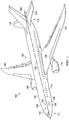
- aircraft 100 has wing 102 and wing 104 attached to fuselage 106.
- Aircraft 100 also includes engine 108 attached to wing 102 and engine 110 attached to wing 104.
- Fuselage 106 has nose section 112 and tail section 114. Nose section 112 is the forward part of aircraft 100, while tail section 114 is the aft part of aircraft 100. Horizontal stabilizer 116, horizontal stabilizer 118, and vertical stabilizer 120 are attached to tail section 114 of fuselage 106.
- Aircraft 100 is an example of a vehicle in which icing condition detection system 122 may be implemented.
- icing condition detection system 122 includes sensor units 124 located on surface 126 of aircraft 100.
- sensor units 124 include sensor unit 128 and sensor unit 130.
- Sensor unit 128 is located on side 132 of aircraft 100.
- Sensor unit 130 is located on side 134 of aircraft 100.
- sensor unit 134 is substantially opposite of sensor unit 128 and is shown in phantom.
- sensor unit 128 and sensor unit 130 may be located substantially at horizontal center line 136 in aircraft 100. A more detailed illustration of sensor unit 128 in location 138 on fuselage 106 is described in more detail below.
- sensor units 124 are configured to collect drops of water that may be present in the air around surface 126 of aircraft 100. These drops of water may be analyzed to determine a presence of a number of types of icing conditions. In these illustrative examples, sensor units 124 may generate images of the drops of water for analysis. The analysis may indicate whether the drops of water are frozen drops of water, the size of the drops of water, and other suitable information that may be used to identify a presence of a number of types of icing conditions.
- these icing conditions may occur at different altitudes and temperatures that cause the formation of ice on aircraft 100.
- icing conditions may be present at an altitude from about sea level to about 30,000 feet when the temperature is from about -40 degrees Celsius to about 0 degrees Celsius.
- other altitudes and temperatures may be present at which ice may be formed from water that contacts surface 126 of aircraft 100.
- Icing conditions also may be present when the liquid water content in the drops is from about 0.4 to about 2.8 grams/cubic meter at the altitude and temperature range described above.
- the number of types of icing conditions may include a first type of icing condition and a second type of icing condition.
- the first type of icing condition and the second type of icing condition are caused by drops of water of different sizes.
- the altitude, temperature, and liquid water content ranges may be the same, one difference between the first and second types of icing conditions is the drop size.
- the first type of icing condition may be referred to as a normal icing condition.
- the second type of icing condition may be referred to as a supercooled large drop icing condition.
- the first type of icing condition may be present when the size of the drops is from about 0.00465 millimeters in diameter to about 0.111 millimeters in diameter. Drops with these sizes may be referred to as normal drops.
- the second type of icing condition may be present when the size of the drops includes drops that have a diameter greater than about 0.111 millimeters. Drops having a size greater than about 0.111 millimeters may be referred to as large drops and, in particular, may be called supercooled large drops under the altitude, temperature, and liquid water content conditions described above. For example, the drops may have a diameter of a range from about 0.112 millimeters to about 2.2 millimeters.
- the second type of icing condition may include drops that are 0.111 millimeters or less when drops greater than 0.111 millimeters are present.
- sensor units 124 are configured to detect drops of water in a first number of sizes. Further, sensor units 124 also are configured to detect drops of water having a second number of sizes. These drops of water may be in a liquid state, a frozen state, or some combination thereof. In these illustrative examples, the first number of sizes is smaller than the second number of sizes.
- the first number of sizes may be from about 0.00465 millimeters in diameter to about 0.111 millimeters in diameter.
- the second number of sizes may be from about 0.112 millimeters to about 2.2 millimeters in diameter.
- the second number of sizes of the drops of water may be drops of water that are considered to be drops of supercooled water. These drops of supercooled water may be supercooled large drops.
- sensor units 124 are not meant to imply limitations to the manner in which sensor units may be implemented in other illustrative examples for aircraft 100 and other aircraft or vehicles in which detection of icing conditions is desired.
- other numbers of sensor units may be used in addition to sensor unit 128 and sensor unit 130 in sensor units 124.
- five sensor units, twelve sensor units, or some other suitable number of sensor units may be employed.
- sensor units also may be placed in other locations such as on vertical stabilizer 120, on engine 110, and other suitable locations.
- sensor units 124 also may be positioned above horizontal center line 136 on aircraft 100.
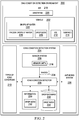
- Icing condition detection environment 200 is an environment in which ice detection may be performed for vehicle 202.
- vehicle 202 may be aircraft 100 in Figure 1 .
- Icing condition detection system 204 may be associated with vehicle 202.
- the association is a physical association in these depicted examples.
- a first component, icing condition detection system 204 may be considered to be associated with a second component, vehicle 202, by being secured to the second component, bonded to the second component, mounted to the second component, welded to the second component, fastened to the second component, and/or connected to the second component in some other suitable manner.
- the first component also may be connected to the second component using a third component.
- the first component may also be considered to be associated with the second component by being formed as part of and/or an extension of the second component.
- icing condition detection system 204 includes sensor system 206 and icing condition detector 208. Icing condition detection system 204 is configured to detect a number of types of icing conditions 210.
- icing condition detection system 204 may be configured to detect whether the number of types of icing conditions 210 are present where ice 212 may be formed on surface 214 of vehicle 202.
- vehicle 202 may take a number of different forms including aircraft 100 in Figure 1 .
- sensor system 206 is a hardware system and may include software. In these illustrative examples, sensor system 206 is comprised of a number of sensor units 216.
- Each sensor unit in the number of sensor units 216 is associated with surface 214 of vehicle 202.
- number of sensor units 216 may be in locations that are exposed to air 218.
- the number of sensor units 216 may be positioned to be within airstream 220 in air 218 around vehicle 202.
- Sensor system 206 is configured to detect drops of water 222.
- the number of sensor units 216 in sensor system 206 may be configured to collect drops of water 222 from air 218 on the exterior of vehicle 202.
- a number of drops of water 222 may be in a liquid state, a frozen state, or some combination thereof.
- the number of drops of water 222 may include frozen drops of water 228. Drops of water 222 may freeze during the collection process performed by sensor system 206 to collect drops of water 222 for analysis.
- sensor system 206 is configured to generate a number of images 224 of drops of water 222 collected by sensor system 206.
- the number of images 224 of drops of water 222 may be analyzed by icing condition detector 208.
- icing condition detector 208 is configured to detect a presence of the number of types of icing conditions 210 for vehicle 202 using the number of images 224 generated by sensor system 206.
- Icing condition detector 208 may be implemented using hardware, software, or some combination thereof.
- the operations performed by icing condition detector 208 may be implemented in program code configured to run on a processor unit.
- the hardware may include circuits that operate to perform the operations in icing condition detector 208.
- the hardware may take the form of a circuit system, an integrated circuit, an application specific integrated circuit (ASIC), a programmable logic device, or some other suitable type of hardware configured to perform a number of operations.
- ASIC application specific integrated circuit
- a programmable logic device the device is configured to perform the number of operations.
- the device may be reconfigured at a later time or may be permanently configured to perform the number of operations.
- programmable logic devices include, for example, a programmable logic array, a programmable array logic, a field programmable logic array, a field programmable gate array, and other suitable hardware devices.
- the processes may be implemented in organic components integrated with inorganic components and/or may be comprised entirely of organic components excluding a human being.
- the processes may be implemented as circuits in organic semiconductors.
- icing condition detector 208 is configured to generate information 230 about drops of water 222 from images 224.
- information 230 may include drop sizes 232 for drops of water 222.
- Drop sizes 232 identified for drops of water 222 may be compared to drop sizes 234 in drop database 236.
- Drop sizes 234 in drop database 236 are sizes for drops of water for different icing conditions in types of icing conditions 210.
- drop sizes 232 may be identified from empirical data.
- the empirical data may be generated from using drops with known sizes that are collected by sensor system 206.
- the measurements may be images of drops of water 222 collected by sensor system 206 from air 218. Drops of water 222 have drop sizes 225, which are known when generating drop database 236.
- drop sizes 232 for drops of water 222 collected on devices such as probes may be different from drops sizes 225 for drops of water 222 in air 218.
- drops of water 222 in the air may have a different size from when drops of water 222 adhere or land on a surface of a device, such as a probe.
- Drop sizes 232 may be correlated to drop sizes 225 when drop sizes 225 are known. This information may be used to create drop database 236 for identifying types of icing conditions 210.
- the comparison of drop sizes 232 for drops of water 222 to drop sizes 234 in drop database 236 may be performed in substantially real time.
- icing condition detector 208 detects drops of water 222 with drop sizes 232
- drop sizes 232 are compared to drop sizes 234 in drop database 236 as fast as possible without intentional delay. In this manner, information 230 may be generated in substantially real time.
- the comparison of drop sizes 232 for drops of water 222 to drop sizes 234 in drop database 236 may be used to identify a presence of a number of types of icing conditions 210 around vehicle 202.
- the type of icing condition or types of icing conditions in types of icing conditions 210 may be identified from this comparison.
- icing condition detector 208 is configured to perform an operation in response to detecting a presence of one or more types of icing conditions 210.
- types of icing conditions 210 may include a first type of icing condition and a second type of icing condition as described above.
- anti-icing system 226 may take a number of different forms.
- anti-icing system 226 may include at least one of an infrared heater, an electrical resistive heater, a de-icer boot, and other suitable types of anti-icing devices.
- Anti-icing system 226 may be used for at least one of reducing the formation of icing, preventing the formation of ice, and removing ice from the surfaces of vehicle 202 in these illustrative examples.
- the phrase "at least one of”, when used with a list of items, means different combinations of one or more of the listed items may be used and only one of each item in the list may be needed.
- “at least one of item A, item B, and item C” may include, without limitation, item A or item A and item B. This example also may include item A, item B, and item C or item B and item C.
- "at least one of” may be, for example, without limitation, two of item A, one of item B, and ten of item C; four of item B and seven of item C; and other suitable combinations.
- icing condition detector 208 also may perform other operations in place of or in addition to activating anti-icing system 226.
- the other operations may include at least one of generating an alert, generating a log entry, sending a report, or other suitable types of operations.
- icing condition detection system 204 is configured to detect different types of icing conditions 210.
- icing condition detection system 204 may provide for automated, real time water drop measurement and for ice detection based on a number of types of icing conditions 210 that may be identified.
- Sensor unit 300 is an example of one implementation of a sensor unit in sensor units 216 for sensor system 206 in Figure 2 .
- Sensor unit 300 includes a number of different types of components in this illustrative example. As depicted, sensor unit 300 includes housing 302, probes 304, actuator system 306, camera system 308, drop remover 310, and controller 312.
- Housing 302 is a physical structure in which the other components in sensor unit 300 may be associated.
- housing 302 may contain or hold the other components in sensor unit 300.
- housing 302 may take a number of different forms.
- housing 302 may have a shape such as a cylinder, a cube, a cuboid, a frustum, and other suitable shapes.
- Housing 302 may be comprised of one or more different types of materials.
- housing 302 may be comprised of at least one of a metal, a plastic, aluminum, titanium, a composite material, and other suitable types of materials.
- Probes 304 are physical structures configured to collect drops of water from the air around the vehicle.
- probes 304 may extend into the air on the exterior of the vehicle and retract out of the air on the exterior of the vehicle to collect drops of water that may be present in the air around the exterior of the vehicle.
- probes 304 may extend into the air on the exterior of the vehicle from the housing and retract out of the air on the exterior of the vehicle into the housing.
- Actuator system 306 is configured to move probes 304 to extend into the air and retract from the air.
- actuator system 306 may cause probes 304 to move out of housing 302 and back into housing 302.
- the movement of probes 304 may be such that only a portion of probes 304 are extended into the air outside of housing 302 while another portion of probes 304 are retracted out of the air inside of housing 302.
- Actuator system 306 is a hardware system and may be implemented using a number of different types of actuators.
- actuator system 306 may include components selected from a motor system such as at least one of an electric motor, a pneumatic motor, and other suitable types of components.
- Camera system 308 is a hardware system and is configured to generate images of drops of water that may be collected on probes 304.
- camera system 308 may generate images of the drops of water when on the portion of probes 304 that are located within housing 302.
- Camera system 308 may be implemented using one or more cameras. In these illustrative examples, camera system 308 may be implemented using visible light cameras. When camera system 308 includes one or more visible light cameras, camera system 308 may include a light source such as a light emitting diode or a flash. This light source provides light for images of drops of water taken by camera system 308 in conditions where the amount of ambient light is insufficient for generating images for analysis. For example, probes 304 may be operated during a night flight of an aircraft with sensor unit 300. The light or flash may be needed to generate images of drops of water captured by probes 304 in this example.
- a light source such as a light emitting diode or a flash. This light source provides light for images of drops of water taken by camera system 308 in conditions where the amount of ambient light is insufficient for generating images for analysis.
- probes 304 may be operated during a night flight of an aircraft with sensor unit 300. The light or flash may be needed to generate images of drops of water captured by probes 304 in this
- camera system 308 may include an infrared camera.
- Drop remover 310 is a hardware system and is configured to remove frozen, liquid, or both frozen and liquid drops of water that may be on probes 304. The removal of the frozen drops of water may occur after camera system 308 has generated the images. Drop remover 310 removes frozen drops of water on probes 304 prior to probes 304 being extended back into the air on the exterior of the vehicle outside of housing 302 in these illustrative examples.
- Drop remover 310 may be implemented using a number of different types of deicing systems.
- drop remover 310 may be a heater configured to melt any drops of water that are frozen on probes 304. This heater may also be configured to evaporate the drops of water on probes 304 that are not yet frozen.
- drop remover 310 may be a mechanical structure that scrapes frozen drops of water off of probes 304. In still other illustrative examples, drop remover 310 may scrape liquid drops of water off of probes 304.
- drop remover 310 may be a de-icing system, a mechanical drop removal system, or a combination thereof.
- Controller 312 is a hardware device configured to control the operation of sensor unit 300.
- controller 312 may be implemented as a circuit and may be an integrated circuit, a processor unit, a programmable logic array, an application specific integrated circuit, or some other suitable type of hardware.
- controller 312 may control the operation of actuator system 306 to move probes 304 into and out of housing 302. Further, controller 312 also may be configured to control the operation of camera system 308 to generate images of drops of water on probes 304. Controller 312 also may be configured to control the operation of drop remover 310 to remove frozen drops of water or other ice from probes 304 prior to probes 304 being moved back outside of housing 302 to collect additional drops of water.
- icing condition detection environment 200 and the different components in icing condition detection environment 200 in Figure 2 and Figure 3 are not meant to imply physical or architectural limitations to the manner in which an illustrative embodiment may be implemented. Other components in addition to or in place of the ones illustrated may be used. Some components may be unnecessary. Also, the blocks are presented to illustrate some functional components. One or more of these blocks may be combined, divided, or combined and divided into different blocks when implemented in an illustrative embodiment.
- icing condition detector 208 is shown as a separate component from sensor system 206, icing condition detector 208 may be distributed in sensor units 216 in addition to being a separate component or in place of being a separate component. Icing condition detector 208 may be located in a camera system, a housing, a computer system, or in some other suitable location in aircraft 100. In still other illustrative examples, sensor system 206 may include other types of sensors configured to detect the presence of ice 212 on surface 214 of vehicle 202, or to detect types of icing conditions 210 that may be present around vehicle 202.
- vehicle 202 may take other forms other than aircraft 100.
- vehicle 202 may be selected from one of, for example, without limitation, a personnel carrier, a tank, a train, an automobile, a bus, a spacecraft, a surface ship, and other suitable vehicles.
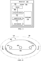
- FIG. 4 an illustration of a sensor unit on an aircraft is depicted in accordance with an illustrative embodiment. As depicted, a more detailed illustration of sensor unit 128 at location 138 in Figure 1 is shown.
- sensor unit 128 has housing 400, which is substantially flush to surface 126 of fuselage 106 in aircraft 100.
- housing 400 includes ports 402.
- ports 402 include port 404, port 406, and port 408.
- ports 402 provide an ability for probes (not shown) to extend from housing 400 to the exterior of aircraft 100 and to retract into housing 400 into the interior of aircraft 100. These probes may extend and retract to collect drops of water in these illustrative examples.
- housing 400 and ports 402 may be implemented in an illustrative embodiment.
- the design of sensor unit 128 may be based on unique aircraft configurations in some illustrative examples.
- probe 500 extends from port 404. Probe 500 may collect drops of water from air around aircraft 100 when in this extended state on the exterior of housing 400 and aircraft 100.
- probe 500 has viscous portion 502.
- Viscous portion 502 may be a coating on the surface of probe 500, an attachment to probe 500, or attached to probe 500 in some other suitable fashion.
- Viscous portion 502 may be comprised of a different type of material than probe 500.
- viscous portion 502 of probe 500 may be comprised of a smooth but erosion-resistant material such as silicon rubber, polytetrafluoroethylene, an oily or waxy resin, or other suitable types of material.
- the material selected for viscous portion 502 of probe 500 may be selected such that viscous portion 502 collects drops of water.
- viscous portion 502 of probe 500 is configured such that all of viscous portion 502 may retract into housing 400 through port 404. In this manner, viscous portion 502 with drops of water may be photographed and images generated may be analyzed by sensor unit 128.
- viscous portion 502 may be larger depending on the particular implementation.
- viscous portion 502 may be configured to cover the entire surface of probe 500.
- viscous portion 502 of probe 500 may be smaller than depicted in this figure.
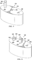
- FIG. 6 another illustration of a sensor unit is depicted in accordance with an illustrative embodiment.
- probe 500 moves in the direction of arrow 600 to retract into housing 400 through port 404.
- probe 602 moves in the direction of arrow 604 to extend outwards to the exterior of housing 400 through port 406.
- probe 602 has viscous portion 606.
- Viscous portion 606 of probe 602 is similar to viscous portion 502 of probe 500.
- Viscous portion 606 is comprised of a material configured to collect drops of water on the surface of viscous portion 606.
- viscous portion 606 of probe 602 is configured such that all of viscous portion 606 may retract into housing 400 through port 406. In this manner, viscous portion 606 with drops of water may be photographed and analyzed by sensor unit 128. In some illustrative examples, viscous portion 606 may be smaller or larger than shown in this figure, depending on the particular implementation.
- FIG. 7 another illustration of a sensor unit is depicted in accordance with an illustrative embodiment.
- probe 602 is shown in a fully extended state outside of housing 400 and probe 500 has been fully retracted into the interior of housing 400.
- probe 602 moves in the direction of arrow 800 to retract into the interior of housing 400 through port 406.
- Probe 802 moves in the direction of arrow 804 to extend outwards to the exterior of housing 400 through port 408.
- probe 802 has viscous portion 808.
- Viscous portion 808 of probe 802 is similar to viscous portion 502 of probe 500 and viscous portion 606 of probe 602.
- Viscous portion 808 is comprised of a material configured to collect drops of water on the surface of viscous portion 808.
- viscous portion 808 of probe 802 is configured such that all of viscous portion 808 may retract into housing 400 through port 408. In this manner, viscous portion 808 with drops of water may be photographed and analyzed by sensor unit 128. In some illustrative examples, viscous portion 808 may be smaller or larger than shown in this figure, depending on the particular implementation.
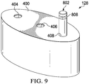
- FIG. 9 another illustration of a sensor unit is depicted in accordance with an illustrative embodiment.
- probe 802 is shown as being fully extended on the exterior of housing 400 and probe 602 has been fully retracted into the interior of housing 400.
- probes such as probe 500, probe 602, and probe 802 may move in a manner such that one of the probes may always be extended to collect drops of water when the sensor unit 128 is used to detect a presence of a number of types of icing conditions.
- a first probe such as probe 500 may be fully retracted before a second probe, such as probe 602, is extended.
- probe 602 with viscous portion 606 may be extended.
- more than one probe may be extended from housing 400 substantially concurrently.
- FIG. 10 an illustration of a cross-sectional view of a sensor unit is depicted in accordance with an illustrative embodiment.
- a cross-sectional view of sensor unit 128 is shown taken along lines 10-10 in Figure 4 .
- probe 500 with viscous portion 502, probe 602 with viscous portion 606, and probe 802 with viscous portion 808 are shown fully retracted into the interior of housing 400.
- Probe 500 is operated by actuator 1000
- probe 602 is operated by actuator 1002
- probe 802 is operated by actuator 1004 in these illustrative examples.
- Actuator 1000, actuator 1002, and actuator 1004 may be physical implementations for actuator system 306 in Figure 3 .
- Actuator 1000, actuator 1002, and actuator 1004 are configured to move probe 500, probe 602, and probe 802, respectively, into the air and retract probe 500, probe 602, and probe 802 into housing 400. Actuator 1000, actuator 1002, and actuator 1004 are controlled by controller 1006. Controller 1006 may be a physical implementation for controller 312 in Figure 3 .
- drop remover 1008 is associated with probe 500
- drop remover 1010 is associated with probe 602
- drop remover 1012 is associated with probe 802.
- Drop remover 1008, drop remover 1010, and drop remover 1012 may be physical implementations for drop remover 310 in Figure 3 .
- drop remover 1008, drop remover 1010, and drop remover 1012 are shown as internal coils in this example. In other illustrative examples, drop remover 1008, drop remover 1010, and drop remover 1012 may be external heaters or associated with the surface of drop remover 1008, drop remover 1010, and drop remover 1012.
- drop remover 1008, drop remover 1010, and drop remover 1012 may be mechanical devices. These mechanical devices may be configured to scrape ice or drops of water off of the surfaces of probe 500, probe 602, and probe 802.
- camera system 1014 is present in housing 400.
- Camera system 1014 is an example of a physical implementation for camera system 308 in Figure 3 .
- Camera system 1014 is configured to generate images of probe 500, probe 602, and probe 802 when at least one of probe 500, probe 602, and probe 802 is retracted in housing 400.
- Camera system 1014 is also operated by controller 1006 in these illustrative examples.
- FIG. 11 an illustration of an isometric view of a sensor unit is depicted in accordance with an illustrative embodiment.
- sensor unit 128 is shown such that probe 500, probe 602, probe 802, and the components in housing 400 are visible.
- actuator 1000 has extended probe 500 into the air. Viscous portion 502 is collecting drops of water in this illustrative example. Probe 602 and probe 802 remain in the interior of housing 400.
- sensor unit 128 in Figure 1 , and Figures 4 -11 are not meant to imply limitations to the manner in which sensor unit 300 may be implemented.
- other sensor units may have other numbers of probes other than the three probes shown for sensor unit 128.
- a sensor unit may include only a single probe, four probes, or some other suitable number of probes.
- the probes also may have other shapes.
- a probe may have a cross section that is oval, rectangular, square, hexagonal, or some shape other than the circular shape shown for probe 500, probe 602, and probe 802.
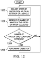
- FIG. 12 an illustration of a flowchart of a process for detecting an icing condition is depicted in accordance with an illustrative embodiment.
- the process illustrated in Figure 12 may be implemented in icing condition detection environment 200 in Figure 2 .
- this process may be implemented using icing condition detection system 204.
- the process begins by collecting drops of water from air on an exterior of a vehicle (operation 1200 ) .
- a number of images of the drops of water collected are generated (operation 1202 ) .
- the process determines whether a number of types of icing conditions is present using the number of images (operation 1204 ) .
- an operation is performed (operation 1206 ) with the process then returning to operation 1200. If a number of types of icing conditions is not present, the process also returns to operation 1200. This process may be repeated as long as monitoring for one or more icing conditions is desired.
- each block in the flowcharts or block diagrams may represent a module, a segment, a function, and/or a portion of an operation or step.
- one or more of the blocks may be implemented as program code, in hardware, or a combination of the program code and hardware.
- the hardware may, for example, take the form of integrated circuits that are manufactured or configured to perform one or more operations in the flowcharts or block diagrams.
- the function or functions noted in the blocks may occur out of the order noted in the figures.
- two blocks shown in succession may be executed substantially concurrently, or the blocks may sometimes be performed in the reverse order, depending upon the functionality involved.
- other blocks may be added in addition to the illustrated blocks in a flowchart or block diagram.
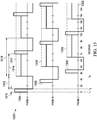
- timing diagram 1300 shows the timing of a cycle of movement of the probes in sensor unit 128 in Figures 4-11 .
- Timing diagram 1300 includes scale 1302 with elapsed time measured in seconds.
- timing diagram 1300 includes line 1304, line 1306, and line 1308.
- Line 1304 tracks the movement over time of "probe A”
- line 1306 tracks the movement over time of "probe B”
- line 1308 tracks the movement over time of "probe C.”
- Probe A may correspond to probe 500
- probe B may correspond to probe 602
- probe C may correspond to probe 802 in Figures 4-11 .
- the cycle time for probe A depicted by line 1304 consists of five seconds in the air stream to sample drops of water in the air during time period 1310, 20 seconds inside the housing to photograph and measure the drops during time period 1312, and 35 seconds to heat or otherwise remove the drops of water from the probe during time period 1314.
- an icing measurement signal is latched for sixty seconds as shown during time period 1316.
- a latched signal may be a signal that is continuously transmitted. The signal may be latched in order to minimize nuisance cycling of ice protection systems.
- the cycle during time period 1310, time period 1312, and time period 1314 may repeat for any number of times for probe A.
- line 1317 indicates the signal being sent by probe A in sensor unit 128.
- This signal may be sent to the flight deck of the aircraft or to other suitable locations to be used in initiating operation of an anti-icing system or other suitable anti-icing measures.
- This signal may be sent continuously between cycles of probe A.
- probe B follows the same cycle as probe A but the cycle is offset by 15 seconds.
- Line 1306 shows the collection, image generation, and drop removal portions of this cycle over time.
- Line 1318 indicates a signal being sent to the flight deck from probe B in sensor unit 128.
- probe C also follows the same cycle as probe A and probe B.
- the cycle time for probe C depicted by line 1306 is delayed by 30 seconds in this illustrative example.
- Line 1320 indicates a signal being sent to the flight deck from probe C.
- sensor unit 128 continuously provides information to the flight deck about icing conditions for the aircraft.
- the aircraft may prevent or remove ice, water, or both ice and water from the surface of the aircraft in substantially real time such that the aircraft operates as desired when icing conditions are present.
- the illustrative embodiments provide a method and apparatus for detecting different types of icing conditions.
- the icing condition detection system may differentiate between types of icing conditions.
- the illustrative embodiments provide more-detailed information about icing conditions than currently used icing detection systems that are unable to differentiate between normal and supercooled large drop icing conditions.
- the illustrative embodiments can accurately measure drop size. These measurements may be made by comparing images of the drops of water collected on the probes to images stored in a database. Moreover, the illustrative embodiments may be operated using less power than currently used icing detection systems. For example, the sensor unit may be placed on "stand-by" until icing conditions are present.
- the icing condition detection system analyzes and classifies the type of icing condition present in the environment around the aircraft. This process alerts the flight deck of icing conditions much more quickly than using other techniques and provides real time updates of the icing conditions surrounding the aircraft.
Landscapes
- Health & Medical Sciences (AREA)
- Life Sciences & Earth Sciences (AREA)
- Chemical & Material Sciences (AREA)
- Engineering & Computer Science (AREA)
- Biochemistry (AREA)
- Physics & Mathematics (AREA)
- Analytical Chemistry (AREA)
- General Health & Medical Sciences (AREA)
- General Physics & Mathematics (AREA)
- Immunology (AREA)
- Pathology (AREA)
- Biomedical Technology (AREA)
- Molecular Biology (AREA)
- Aviation & Aerospace Engineering (AREA)
- Dispersion Chemistry (AREA)
- Investigating Or Analysing Materials By Optical Means (AREA)
- Sampling And Sample Adjustment (AREA)
Claims (15)
- Dispositif, comprenant :un système de capteur (206) configuré pour collecter, à partir de l'air (218) sur l'extérieur d'un aéronef (100), des gouttes d'eau (222) et générer un nombre d'images (224) des gouttes d'eau (222) collectées ; etun détecteur d'état de givrage (208) configuré pour détecter une présence d'un nombre de types d'états de givrage (210) pour l'aéronef 100 en utilisant le nombre d'images (224) provenant du système de capteur (206).
- Dispositif selon la revendication 1, dans lequel le détecteur d'état de givrage (208) est en outre configuré pour effectuer un fonctionnement (1206) en réponse à la détection d'une présence d'au moins un d'un premier type d'état de givrage et d'un second type d'état de givrage.
- Dispositif selon la revendication 2, dans lequel le fonctionnement (1206) est choisi parmi au moins un fonctionnement de génération d'une alerte, d'activation d'un système d'anti-givrage, de génération d'une inscription dans le livre de bord, et d'envoi un rapport.
- Dispositif selon la revendication 1, 2 ou 3, dans lequel le système de capteur (206) comprend :un nombre de sondes (304) configuré pour collecter, à partir de l'air (218) sur l'extérieur de l'aéronef (100), les gouttes d'eau (222) etun système d'appareil-photo (308) configuré pour générer le nombre d'images (224) des gouttes d'eau (222) collectées par le nombre de sondes (304).
- Dispositif selon la revendication 4, dans lequel le nombre de sondes (304) est configuré pour se déployer dans l'air (218) sur l'extérieur de l'aéronef (100) et retirer le nombre de sondes 304 de l'air (218) sur l'extérieur de l'aéronef (100) jusqu'à l'intérieur de l'aéronef (100).
- Dispositif selon les revendications 4 à 5, dans lequel le nombre de sondes (304) est configuré pour se déployer périodiquement dans l'air (218) sur l'extérieur de l'aéronef (100) et se retirer de l'air (218) sur l'extérieur de l'aéronef (100).
- Dispositif selon la revendication 5, comprenant en outre :un logement (302, 400), dans lequel le système d'appareil-photo (308, 1014) est situé à l'intérieur du logement (302) et le nombre de sondes (304) est configuré pour se déployer dans l'air (218) sur l'extérieur de l'aéronef (100) depuis le logement (302, 400) et se retirer de l'air (218) sur l'extérieur de l'aéronef (100) jusque dans le logement (302, 400) ; etun système de moteur configuré pour déplacer le nombre de sondes (304) pour se déployer dans l'air (218) sur l'extérieur de l'aéronef (100) depuis le logement (302, 400) et se retirer de l'air (21 8) sur l'extérieur de l'aéronef (100) jusque dans le logement (302. 400).
- Dispositif selon la revendication 5, dans lequel le détecteur d'état de givrage (208) est configuré pour analyser le nombre d'images (224) afin d'identifier un type d'état de givrage pour l'aéronef (100) lorsque les gouttes d'eau (222 collectées sont des gouttes d'eau gelées (228) en comparant une taille de gouttes d'eau gelées (228) dans le nombre d'images (224) avec une base de données (236) de tailles de gouttes (225) pour les gouttes d'eau gelées (228).
- Dispositif selon la revendication 8, dans lequel le détecteur d'état de givrage (208) est situé dans un emplacement parmi le système d'appareil-photo (308, 1014), un logement (302), et un système informatique dans le l'aéronef (100).
- Dispositif selon la revendication 2, dans lequel le premier type d'état de givrage est causé par des premières gouttes (222) ayant un premier nombre de tailles (225) allant d'environ 0,00465 millimètres de diamètre à environ 0,111 millimètres de diamètre et le second type d'état de givrage est causé par des secondes gouttes (222) ayant un second nombre de tailles (225) allant d'environ 0,112 millimètres de diamètre à environ 2,2 millimètres de diamètre.
- Dispositif selon la revendication 1, comprenant en outre :un groupe d'unités de capteur (124, 216), dans lequel une unité de capteur (128, 130, 300) dans le groupe d'unités de capteur (124, 216) comprend un nombre de sondes (304) configuré pour collecter, à partir de l'air (218) sur l'extérieur de l'aéronef (100), des gouttes d'eau et un système d'appareil-photo (308, 1014) configuré pour générer un nombre d'images (224) des gouttes d'eau (222) collectées par le nombre de sondes (304) ; etun système d'anti-givrage (226) configuré pour enlever la glace d'une surface de l'aéronef 100 lorsque la présence du nombre de de types d'états de givrage (210) est présente.
- Procédé de détection d'un état de givrage, le procédé consistant à :collecter, à partir de l'air (218) sur l'extérieur d'un aéronef (100), des gouttes d'eau (222) ;générer un ombre d'images (224) des gouttes d'eau (222) collectées ; etdéterminer si un nombre de types d'états de givrage (210) pour l'aéronef 100 est présent en utilisant le nombre d'images (224) provenant d'un système de capteur (206).
- Procédé selon la revendication 12, consistant en outre à :effectuer un fonctionnement (1206) lorsque le nombre de types d'états de givrage (210) est présent.
- Procédé selon la revendication 12 ou 13, dans lequel l'étape de collecte consiste à :déplacer un nombre de sondes (304) pour qu'elles se déploient dans l'air (21 8) sur l'extérieur de l'aéronef (100) et se retirent de l'air (218) sur l'extérieur de l'aéronef (100) jusqu'à l'intérieur de l'aéronef (100); et dans lequel l'étape de génération consiste à :générer les images (224) des gouttes d'eau (222) collectées sur le nombre de sondes (304) sous forme de gouttes d'eau gelées (228) lorsque le nombre de sondes (304) sont retirées de l'air (218) sur l'extérieur de l'aéronef (100) jusqu'à l'intérieur de l'aéronef (100).
- Procédé selon la revendication 14, dans lequel l'étape de collecte consiste en outre à :faire fondre les gouttes d'eau gelées (228) après la génération des images (224) et avant le déplacement du nombre de sondes (304) pour se redéployer dans l'air (218) sur l'extérieur de l'aéronef (100).
Applications Claiming Priority (1)
| Application Number | Priority Date | Filing Date | Title |
|---|---|---|---|
| US13/732,707 US9227733B2 (en) | 2013-01-02 | 2013-01-02 | Automated water drop measurement and ice detection system |
Publications (2)
| Publication Number | Publication Date |
|---|---|
| EP2774851A1 EP2774851A1 (fr) | 2014-09-10 |
| EP2774851B1 true EP2774851B1 (fr) | 2017-03-22 |
Family
ID=49955126
Family Applications (1)
| Application Number | Title | Priority Date | Filing Date |
|---|---|---|---|
| EP13196534.5A Active EP2774851B1 (fr) | 2013-01-02 | 2013-12-10 | Système automatique de détection de glace et de mesure de chute d'eau |
Country Status (7)
| Country | Link |
|---|---|
| US (1) | US9227733B2 (fr) |
| EP (1) | EP2774851B1 (fr) |
| JP (1) | JP6351968B2 (fr) |
| CN (1) | CN103910062B (fr) |
| BR (1) | BR102013033738B1 (fr) |
| CA (1) | CA2829887C (fr) |
| RU (1) | RU2586914C2 (fr) |
Families Citing this family (22)
| Publication number | Priority date | Publication date | Assignee | Title |
|---|---|---|---|---|
| CN102336272B (zh) * | 2010-07-16 | 2015-01-14 | 中国商用飞机有限责任公司 | 结冰探测器探头及包括该探头的结冰探测器 |
| IL230706B (en) | 2014-01-29 | 2019-02-28 | Levkovitch Michael | Ice detection device |
| KR101710161B1 (ko) * | 2014-12-12 | 2017-02-24 | 한국항공우주산업 주식회사 | 회전익 항공기 결빙 시험장치 |
| US20160376010A1 (en) * | 2015-06-26 | 2016-12-29 | Rosemount Aerospace Inc. | Systems and methods for preventing ice accumulation |
| CN105644791B (zh) * | 2015-08-31 | 2018-06-22 | 中国商用飞机有限责任公司 | 结冰探测系统及具有该结冰系统的飞行器 |
| US10737793B2 (en) * | 2015-12-02 | 2020-08-11 | The Boeing Company | Aircraft ice detection systems and methods |
| CN105865100B (zh) * | 2016-04-05 | 2018-03-16 | 北京航空航天大学 | 一种样件弹射式过冷液滴撞击微观观测系统 |
| CN105891206B (zh) * | 2016-04-05 | 2018-07-24 | 北京航空航天大学 | 一种可控的过冷液滴连续撞击微观观测系统 |
| GB201608945D0 (en) * | 2016-05-20 | 2016-07-06 | Gkn Aerospace Services Ltd | Ice accretion apparatus |
| CN105882978B (zh) * | 2016-06-24 | 2017-10-13 | 北京航空航天大学 | 一种采用喷射头喷射结冰凝结核及除冰液的直升机旋翼防/除冰方法 |
| US10124900B2 (en) | 2016-06-28 | 2018-11-13 | Rosemount Aerospace Inc. | Automated super-cooled water-droplet size differentiation using aircraft accretion patterns |
| CN107132278B (zh) * | 2017-06-07 | 2023-04-07 | 中国空气动力研究与发展中心低速空气动力研究所 | 一种多圆柱阵列结冰探测方法 |
| IL253739B (en) | 2017-07-31 | 2021-01-31 | Israel Aerospace Ind Ltd | Baldness detector |
| US20190039742A1 (en) * | 2017-08-01 | 2019-02-07 | Honeywell International Inc. | Managing response to icing threat |
| CN107697287B (zh) * | 2017-10-23 | 2023-05-09 | 天津飞眼无人机科技有限公司 | 一种水空两用交通工具的控制系统 |
| CN109903632A (zh) * | 2019-04-18 | 2019-06-18 | 哈尔滨工程大学 | 一种对流条件下水滴撞击冷壁面结冰过程可视化实验平台 |
| CN110127061A (zh) * | 2019-05-13 | 2019-08-16 | 成都凯天电子股份有限公司 | 提高结冰探测器探测杆敏感度的方法 |
| CN110077601A (zh) * | 2019-05-16 | 2019-08-02 | 中国商用飞机有限责任公司 | 过冷水滴结冰探测器和混合态结冰探测器 |
| CN112507572B (zh) * | 2021-02-07 | 2021-04-30 | 中国空气动力研究与发展中心低速空气动力研究所 | 一种过冷大水滴结冰条件的优化匹配评估方法 |
| CN114152365B (zh) * | 2022-02-07 | 2022-04-12 | 中国空气动力研究与发展中心低速空气动力研究所 | 一种临界防冰保护的光纤结冰传感器、系统和方法 |
| US11912420B2 (en) * | 2022-04-11 | 2024-02-27 | The Boeing Company | Deicing systems and methods for an aircraft |
| CN115248022B (zh) * | 2022-09-22 | 2022-12-06 | 四川大学 | 一种输电线路的结冰厚度检测方法 |
Family Cites Families (14)
| Publication number | Priority date | Publication date | Assignee | Title |
|---|---|---|---|---|
| JPH10261064A (ja) * | 1997-03-17 | 1998-09-29 | Mitsuba Corp | 雨滴検出装置における付着物識別方法 |
| JP4257627B2 (ja) * | 1999-11-19 | 2009-04-22 | 日本精機株式会社 | 雨滴検出装置 |
| US6759962B2 (en) * | 2001-04-25 | 2004-07-06 | Rosemount Aerospace Inc. | Inflight ice detector to distinguish supercooled large droplet (SLD) icing |
| JP2004534948A (ja) * | 2001-06-29 | 2004-11-18 | ローズマウント エアロスペース インコーポレイテッド | 過冷却された大きな滴氷検出器 |
| EP1396425A1 (fr) | 2003-03-10 | 2004-03-10 | Auxitrol SA | Détecteur pour spectre de givrage élargi |
| US7324001B2 (en) * | 2005-08-29 | 2008-01-29 | United States Of America As Represented By The Secretary Of The Air Force | System and method for detecting and discriminating between water and ice formation on objects |
| US20070074415A1 (en) | 2005-09-30 | 2007-04-05 | Gagnon Robert E | Method and apparatus for layer thickness measurement |
| NO324138B1 (no) * | 2006-05-08 | 2007-09-03 | Norsk Miljokraft Forskning Og | Fremgangsmate og anordning for styring av effekt til en utrustning for a motvirke isdannelse eller fjerning av sno/is pa en konstruksjonsdel |
| US7439877B1 (en) * | 2007-05-18 | 2008-10-21 | Philip Onni Jarvinen | Total impedance and complex dielectric property ice detection system |
| US20100020170A1 (en) * | 2008-07-24 | 2010-01-28 | Higgins-Luthman Michael J | Vehicle Imaging System |
| US8144325B2 (en) * | 2009-07-23 | 2012-03-27 | Rosemount Aerospace, Inc. | In-flight multiple field of view detector for supercooled airborne water droplets |
| EP2325083B1 (fr) * | 2009-11-24 | 2012-02-08 | AGUSTAWESTLAND S.p.A. | Aéronef avec un indicateur de givrage |
| US8462354B2 (en) * | 2010-10-12 | 2013-06-11 | Lumen International Inc. | Aircraft icing detector |
| US9126692B2 (en) * | 2012-07-31 | 2015-09-08 | Raytheon Company | Remote actuation system for a human/machine interface |
-
2013
- 2013-01-02 US US13/732,707 patent/US9227733B2/en active Active
- 2013-10-10 CA CA2829887A patent/CA2829887C/fr active Active
- 2013-12-10 EP EP13196534.5A patent/EP2774851B1/fr active Active
- 2013-12-13 RU RU2013155544/11A patent/RU2586914C2/ru active
- 2013-12-18 JP JP2013261637A patent/JP6351968B2/ja active Active
- 2013-12-27 BR BR102013033738-2A patent/BR102013033738B1/pt active IP Right Grant
-
2014
- 2014-01-02 CN CN201410001154.2A patent/CN103910062B/zh active Active
Non-Patent Citations (1)
| Title |
|---|
| None * |
Also Published As
| Publication number | Publication date |
|---|---|
| EP2774851A1 (fr) | 2014-09-10 |
| US20140184789A1 (en) | 2014-07-03 |
| CN103910062A (zh) | 2014-07-09 |
| JP6351968B2 (ja) | 2018-07-04 |
| BR102013033738B1 (pt) | 2021-11-03 |
| JP2014131906A (ja) | 2014-07-17 |
| CA2829887C (fr) | 2016-06-07 |
| CN103910062B (zh) | 2017-07-28 |
| US9227733B2 (en) | 2016-01-05 |
| RU2586914C2 (ru) | 2016-06-10 |
| BR102013033738A2 (pt) | 2015-10-06 |
| RU2013155544A (ru) | 2015-06-20 |
| CA2829887A1 (fr) | 2014-07-02 |
Similar Documents
| Publication | Publication Date | Title |
|---|---|---|
| EP2774851B1 (fr) | Système automatique de détection de glace et de mesure de chute d'eau | |
| EP3299294B1 (fr) | Système et procédé de dégivrage d'une surface d'avion | |
| US10124901B2 (en) | Icing condition detection method | |
| US10429511B2 (en) | Light detection and ranging (LIDAR) ice detection system | |
| EP2639158B1 (fr) | Système à laser pour la détection de conditions de givrage | |
| EP2800690B1 (fr) | Système de détection d'une condition de givrage à grosses gouttes surfondues | |
| US9555894B2 (en) | Aircraft ice protection optimization based on ice-detection input | |
| US8704181B2 (en) | Device and method for detecting ice deposited on an aircraft structure | |
| EP2636599B1 (fr) | Système de détection d'état de givrage de goutte d'eau de grande taille en surfusion | |
| US9180972B2 (en) | Supercooled large drop icing condition detection system | |
| US10214299B2 (en) | Light detection and ranging (LIDAR) ice detection | |
| KR20130115563A (ko) | 에어포일 임계 결빙형상을 결정하는 방법 | |
| Al-Masri | Experimental investigation on the icing physics and anti-/de-Icing technology of an aircraft pitot probe | |
| Adeel et al. | A review of infrared thermography applications for ice detection and mitigation |
Legal Events
| Date | Code | Title | Description |
|---|---|---|---|
| PUAI | Public reference made under article 153(3) epc to a published international application that has entered the european phase |
Free format text: ORIGINAL CODE: 0009012 |
|
| 17P | Request for examination filed |
Effective date: 20131210 |
|
| AK | Designated contracting states |
Kind code of ref document: A1 Designated state(s): AL AT BE BG CH CY CZ DE DK EE ES FI FR GB GR HR HU IE IS IT LI LT LU LV MC MK MT NL NO PL PT RO RS SE SI SK SM TR |
|
| AX | Request for extension of the european patent |
Extension state: BA ME |
|
| RIC1 | Information provided on ipc code assigned before grant |
Ipc: B64D 15/20 20060101AFI20160715BHEP |
|
| GRAP | Despatch of communication of intention to grant a patent |
Free format text: ORIGINAL CODE: EPIDOSNIGR1 |
|
| INTG | Intention to grant announced |
Effective date: 20160826 |
|
| GRAS | Grant fee paid |
Free format text: ORIGINAL CODE: EPIDOSNIGR3 |
|
| GRAJ | Information related to disapproval of communication of intention to grant by the applicant or resumption of examination proceedings by the epo deleted |
Free format text: ORIGINAL CODE: EPIDOSDIGR1 |
|
| GRAL | Information related to payment of fee for publishing/printing deleted |
Free format text: ORIGINAL CODE: EPIDOSDIGR3 |
|
| INTC | Intention to grant announced (deleted) | ||
| GRAR | Information related to intention to grant a patent recorded |
Free format text: ORIGINAL CODE: EPIDOSNIGR71 |
|
| GRAA | (expected) grant |
Free format text: ORIGINAL CODE: 0009210 |
|
| AK | Designated contracting states |
Kind code of ref document: B1 Designated state(s): AL AT BE BG CH CY CZ DE DK EE ES FI FR GB GR HR HU IE IS IT LI LT LU LV MC MK MT NL NO PL PT RO RS SE SI SK SM TR |
|
| INTG | Intention to grant announced |
Effective date: 20170213 |
|
| REG | Reference to a national code |
Ref country code: GB Ref legal event code: FG4D |
|
| REG | Reference to a national code |
Ref country code: CH Ref legal event code: EP |
|
| REG | Reference to a national code |
Ref country code: AT Ref legal event code: REF Ref document number: 877461 Country of ref document: AT Kind code of ref document: T Effective date: 20170415 |
|
| REG | Reference to a national code |
Ref country code: IE Ref legal event code: FG4D |
|
| REG | Reference to a national code |
Ref country code: DE Ref legal event code: R096 Ref document number: 602013018827 Country of ref document: DE |
|
| REG | Reference to a national code |
Ref country code: NL Ref legal event code: MP Effective date: 20170322 |
|
| PG25 | Lapsed in a contracting state [announced via postgrant information from national office to epo] |
Ref country code: NO Free format text: LAPSE BECAUSE OF FAILURE TO SUBMIT A TRANSLATION OF THE DESCRIPTION OR TO PAY THE FEE WITHIN THE PRESCRIBED TIME-LIMIT Effective date: 20170622 Ref country code: GR Free format text: LAPSE BECAUSE OF FAILURE TO SUBMIT A TRANSLATION OF THE DESCRIPTION OR TO PAY THE FEE WITHIN THE PRESCRIBED TIME-LIMIT Effective date: 20170623 Ref country code: FI Free format text: LAPSE BECAUSE OF FAILURE TO SUBMIT A TRANSLATION OF THE DESCRIPTION OR TO PAY THE FEE WITHIN THE PRESCRIBED TIME-LIMIT Effective date: 20170322 Ref country code: HR Free format text: LAPSE BECAUSE OF FAILURE TO SUBMIT A TRANSLATION OF THE DESCRIPTION OR TO PAY THE FEE WITHIN THE PRESCRIBED TIME-LIMIT Effective date: 20170322 Ref country code: LT Free format text: LAPSE BECAUSE OF FAILURE TO SUBMIT A TRANSLATION OF THE DESCRIPTION OR TO PAY THE FEE WITHIN THE PRESCRIBED TIME-LIMIT Effective date: 20170322 |
|
| REG | Reference to a national code |
Ref country code: LT Ref legal event code: MG4D |
|
| REG | Reference to a national code |
Ref country code: AT Ref legal event code: MK05 Ref document number: 877461 Country of ref document: AT Kind code of ref document: T Effective date: 20170322 |
|
| PG25 | Lapsed in a contracting state [announced via postgrant information from national office to epo] |
Ref country code: SE Free format text: LAPSE BECAUSE OF FAILURE TO SUBMIT A TRANSLATION OF THE DESCRIPTION OR TO PAY THE FEE WITHIN THE PRESCRIBED TIME-LIMIT Effective date: 20170322 Ref country code: LV Free format text: LAPSE BECAUSE OF FAILURE TO SUBMIT A TRANSLATION OF THE DESCRIPTION OR TO PAY THE FEE WITHIN THE PRESCRIBED TIME-LIMIT Effective date: 20170322 Ref country code: BG Free format text: LAPSE BECAUSE OF FAILURE TO SUBMIT A TRANSLATION OF THE DESCRIPTION OR TO PAY THE FEE WITHIN THE PRESCRIBED TIME-LIMIT Effective date: 20170622 Ref country code: RS Free format text: LAPSE BECAUSE OF FAILURE TO SUBMIT A TRANSLATION OF THE DESCRIPTION OR TO PAY THE FEE WITHIN THE PRESCRIBED TIME-LIMIT Effective date: 20170322 |
|
| PG25 | Lapsed in a contracting state [announced via postgrant information from national office to epo] |
Ref country code: NL Free format text: LAPSE BECAUSE OF FAILURE TO SUBMIT A TRANSLATION OF THE DESCRIPTION OR TO PAY THE FEE WITHIN THE PRESCRIBED TIME-LIMIT Effective date: 20170322 |
|
| PG25 | Lapsed in a contracting state [announced via postgrant information from national office to epo] |
Ref country code: IT Free format text: LAPSE BECAUSE OF FAILURE TO SUBMIT A TRANSLATION OF THE DESCRIPTION OR TO PAY THE FEE WITHIN THE PRESCRIBED TIME-LIMIT Effective date: 20170322 Ref country code: SK Free format text: LAPSE BECAUSE OF FAILURE TO SUBMIT A TRANSLATION OF THE DESCRIPTION OR TO PAY THE FEE WITHIN THE PRESCRIBED TIME-LIMIT Effective date: 20170322 Ref country code: CZ Free format text: LAPSE BECAUSE OF FAILURE TO SUBMIT A TRANSLATION OF THE DESCRIPTION OR TO PAY THE FEE WITHIN THE PRESCRIBED TIME-LIMIT Effective date: 20170322 Ref country code: AT Free format text: LAPSE BECAUSE OF FAILURE TO SUBMIT A TRANSLATION OF THE DESCRIPTION OR TO PAY THE FEE WITHIN THE PRESCRIBED TIME-LIMIT Effective date: 20170322 Ref country code: RO Free format text: LAPSE BECAUSE OF FAILURE TO SUBMIT A TRANSLATION OF THE DESCRIPTION OR TO PAY THE FEE WITHIN THE PRESCRIBED TIME-LIMIT Effective date: 20170322 Ref country code: ES Free format text: LAPSE BECAUSE OF FAILURE TO SUBMIT A TRANSLATION OF THE DESCRIPTION OR TO PAY THE FEE WITHIN THE PRESCRIBED TIME-LIMIT Effective date: 20170322 Ref country code: EE Free format text: LAPSE BECAUSE OF FAILURE TO SUBMIT A TRANSLATION OF THE DESCRIPTION OR TO PAY THE FEE WITHIN THE PRESCRIBED TIME-LIMIT Effective date: 20170322 |
|
| PG25 | Lapsed in a contracting state [announced via postgrant information from national office to epo] |
Ref country code: SM Free format text: LAPSE BECAUSE OF FAILURE TO SUBMIT A TRANSLATION OF THE DESCRIPTION OR TO PAY THE FEE WITHIN THE PRESCRIBED TIME-LIMIT Effective date: 20170322 Ref country code: PL Free format text: LAPSE BECAUSE OF FAILURE TO SUBMIT A TRANSLATION OF THE DESCRIPTION OR TO PAY THE FEE WITHIN THE PRESCRIBED TIME-LIMIT Effective date: 20170322 Ref country code: PT Free format text: LAPSE BECAUSE OF FAILURE TO SUBMIT A TRANSLATION OF THE DESCRIPTION OR TO PAY THE FEE WITHIN THE PRESCRIBED TIME-LIMIT Effective date: 20170724 Ref country code: IS Free format text: LAPSE BECAUSE OF FAILURE TO SUBMIT A TRANSLATION OF THE DESCRIPTION OR TO PAY THE FEE WITHIN THE PRESCRIBED TIME-LIMIT Effective date: 20170722 |
|
| REG | Reference to a national code |
Ref country code: FR Ref legal event code: PLFP Year of fee payment: 5 |
|
| REG | Reference to a national code |
Ref country code: DE Ref legal event code: R097 Ref document number: 602013018827 Country of ref document: DE |
|
| PLBE | No opposition filed within time limit |
Free format text: ORIGINAL CODE: 0009261 |
|
| STAA | Information on the status of an ep patent application or granted ep patent |
Free format text: STATUS: NO OPPOSITION FILED WITHIN TIME LIMIT |
|
| PG25 | Lapsed in a contracting state [announced via postgrant information from national office to epo] |
Ref country code: DK Free format text: LAPSE BECAUSE OF FAILURE TO SUBMIT A TRANSLATION OF THE DESCRIPTION OR TO PAY THE FEE WITHIN THE PRESCRIBED TIME-LIMIT Effective date: 20170322 |
|
| 26N | No opposition filed |
Effective date: 20180102 |
|
| PG25 | Lapsed in a contracting state [announced via postgrant information from national office to epo] |
Ref country code: SI Free format text: LAPSE BECAUSE OF FAILURE TO SUBMIT A TRANSLATION OF THE DESCRIPTION OR TO PAY THE FEE WITHIN THE PRESCRIBED TIME-LIMIT Effective date: 20170322 |
|
| REG | Reference to a national code |
Ref country code: CH Ref legal event code: PL |
|
| REG | Reference to a national code |
Ref country code: IE Ref legal event code: MM4A |
|
| PG25 | Lapsed in a contracting state [announced via postgrant information from national office to epo] |
Ref country code: MT Free format text: LAPSE BECAUSE OF NON-PAYMENT OF DUE FEES Effective date: 20171210 Ref country code: LU Free format text: LAPSE BECAUSE OF NON-PAYMENT OF DUE FEES Effective date: 20171210 |
|
| REG | Reference to a national code |
Ref country code: BE Ref legal event code: MM Effective date: 20171231 |
|
| PG25 | Lapsed in a contracting state [announced via postgrant information from national office to epo] |
Ref country code: IE Free format text: LAPSE BECAUSE OF NON-PAYMENT OF DUE FEES Effective date: 20171210 |
|
| PG25 | Lapsed in a contracting state [announced via postgrant information from national office to epo] |
Ref country code: BE Free format text: LAPSE BECAUSE OF NON-PAYMENT OF DUE FEES Effective date: 20171231 Ref country code: CH Free format text: LAPSE BECAUSE OF NON-PAYMENT OF DUE FEES Effective date: 20171231 Ref country code: LI Free format text: LAPSE BECAUSE OF NON-PAYMENT OF DUE FEES Effective date: 20171231 |
|
| PG25 | Lapsed in a contracting state [announced via postgrant information from national office to epo] |
Ref country code: HU Free format text: LAPSE BECAUSE OF FAILURE TO SUBMIT A TRANSLATION OF THE DESCRIPTION OR TO PAY THE FEE WITHIN THE PRESCRIBED TIME-LIMIT; INVALID AB INITIO Effective date: 20131210 Ref country code: MC Free format text: LAPSE BECAUSE OF FAILURE TO SUBMIT A TRANSLATION OF THE DESCRIPTION OR TO PAY THE FEE WITHIN THE PRESCRIBED TIME-LIMIT Effective date: 20170322 |
|
| PG25 | Lapsed in a contracting state [announced via postgrant information from national office to epo] |
Ref country code: CY Free format text: LAPSE BECAUSE OF NON-PAYMENT OF DUE FEES Effective date: 20170322 |
|
| PG25 | Lapsed in a contracting state [announced via postgrant information from national office to epo] |
Ref country code: MK Free format text: LAPSE BECAUSE OF FAILURE TO SUBMIT A TRANSLATION OF THE DESCRIPTION OR TO PAY THE FEE WITHIN THE PRESCRIBED TIME-LIMIT Effective date: 20170322 |
|
| PG25 | Lapsed in a contracting state [announced via postgrant information from national office to epo] |
Ref country code: TR Free format text: LAPSE BECAUSE OF FAILURE TO SUBMIT A TRANSLATION OF THE DESCRIPTION OR TO PAY THE FEE WITHIN THE PRESCRIBED TIME-LIMIT Effective date: 20170322 |
|
| PG25 | Lapsed in a contracting state [announced via postgrant information from national office to epo] |
Ref country code: AL Free format text: LAPSE BECAUSE OF FAILURE TO SUBMIT A TRANSLATION OF THE DESCRIPTION OR TO PAY THE FEE WITHIN THE PRESCRIBED TIME-LIMIT Effective date: 20170322 |
|
| REG | Reference to a national code |
Ref country code: DE Ref legal event code: R082 Ref document number: 602013018827 Country of ref document: DE Representative=s name: KILBURN & STRODE LLP, NL |
|
| P01 | Opt-out of the competence of the unified patent court (upc) registered |
Effective date: 20230516 |
|
| PGFP | Annual fee paid to national office [announced via postgrant information from national office to epo] |
Ref country code: GB Payment date: 20231227 Year of fee payment: 11 |
|
| PGFP | Annual fee paid to national office [announced via postgrant information from national office to epo] |
Ref country code: FR Payment date: 20231227 Year of fee payment: 11 |
|
| PGFP | Annual fee paid to national office [announced via postgrant information from national office to epo] |
Ref country code: DE Payment date: 20231229 Year of fee payment: 11 |