EP2800690B1 - Système de détection d'une condition de givrage à grosses gouttes surfondues - Google Patents
Système de détection d'une condition de givrage à grosses gouttes surfondues Download PDFInfo
- Publication number
- EP2800690B1 EP2800690B1 EP12818681.4A EP12818681A EP2800690B1 EP 2800690 B1 EP2800690 B1 EP 2800690B1 EP 12818681 A EP12818681 A EP 12818681A EP 2800690 B1 EP2800690 B1 EP 2800690B1
- Authority
- EP
- European Patent Office
- Prior art keywords
- aircraft
- group
- sensors
- icing condition
- type
- Prior art date
- Legal status (The legal status is an assumption and is not a legal conclusion. Google has not performed a legal analysis and makes no representation as to the accuracy of the status listed.)
- Active
Links
- 238000001514 detection method Methods 0.000 title claims description 86
- 238000000034 method Methods 0.000 claims description 57
- 230000009471 action Effects 0.000 claims description 23
- 230000004044 response Effects 0.000 claims description 13
- 230000003213 activating effect Effects 0.000 claims description 6
- 230000000977 initiatory effect Effects 0.000 claims description 6
- 238000012544 monitoring process Methods 0.000 claims description 5
- XLYOFNOQVPJJNP-UHFFFAOYSA-N water Substances O XLYOFNOQVPJJNP-UHFFFAOYSA-N 0.000 description 157
- 230000008569 process Effects 0.000 description 26
- 238000013461 design Methods 0.000 description 25
- 238000004891 communication Methods 0.000 description 18
- 238000004519 manufacturing process Methods 0.000 description 13
- 238000012545 processing Methods 0.000 description 12
- 230000015572 biosynthetic process Effects 0.000 description 10
- 230000000712 assembly Effects 0.000 description 8
- 238000000429 assembly Methods 0.000 description 8
- 239000007788 liquid Substances 0.000 description 8
- 230000002085 persistent effect Effects 0.000 description 8
- 238000004088 simulation Methods 0.000 description 7
- 230000008014 freezing Effects 0.000 description 6
- 238000007710 freezing Methods 0.000 description 6
- 238000007726 management method Methods 0.000 description 6
- 239000000523 sample Substances 0.000 description 6
- 230000006870 function Effects 0.000 description 5
- 230000004048 modification Effects 0.000 description 5
- 238000012986 modification Methods 0.000 description 5
- 239000003381 stabilizer Substances 0.000 description 5
- 238000010586 diagram Methods 0.000 description 4
- 230000007246 mechanism Effects 0.000 description 4
- 230000003287 optical effect Effects 0.000 description 4
- LYCAIKOWRPUZTN-UHFFFAOYSA-N Ethylene glycol Chemical compound OCCO LYCAIKOWRPUZTN-UHFFFAOYSA-N 0.000 description 3
- 150000001875 compounds Chemical class 0.000 description 3
- 239000012530 fluid Substances 0.000 description 3
- 238000012935 Averaging Methods 0.000 description 2
- 230000008859 change Effects 0.000 description 2
- 238000004590 computer program Methods 0.000 description 2
- 230000007613 environmental effect Effects 0.000 description 2
- 238000010438 heat treatment Methods 0.000 description 2
- 238000005286 illumination Methods 0.000 description 2
- 230000010354 integration Effects 0.000 description 2
- 238000012423 maintenance Methods 0.000 description 2
- 239000000126 substance Substances 0.000 description 2
- 239000013526 supercooled liquid Substances 0.000 description 2
- 238000009825 accumulation Methods 0.000 description 1
- 230000002528 anti-freeze Effects 0.000 description 1
- 230000033228 biological regulation Effects 0.000 description 1
- 239000013078 crystal Substances 0.000 description 1
- 230000009977 dual effect Effects 0.000 description 1
- 229940093476 ethylene glycol Drugs 0.000 description 1
- 230000004927 fusion Effects 0.000 description 1
- 239000000463 material Substances 0.000 description 1
- 239000013307 optical fiber Substances 0.000 description 1
- 230000008520 organization Effects 0.000 description 1
- 230000010287 polarization Effects 0.000 description 1
- 230000002265 prevention Effects 0.000 description 1
- 230000002250 progressing effect Effects 0.000 description 1
- 230000000644 propagated effect Effects 0.000 description 1
- 230000005855 radiation Effects 0.000 description 1
- 238000009419 refurbishment Methods 0.000 description 1
- 230000001105 regulatory effect Effects 0.000 description 1
- 230000003068 static effect Effects 0.000 description 1
- 230000000007 visual effect Effects 0.000 description 1
Images


Classifications
-
- B—PERFORMING OPERATIONS; TRANSPORTING
- B64—AIRCRAFT; AVIATION; COSMONAUTICS
- B64D—EQUIPMENT FOR FITTING IN OR TO AIRCRAFT; FLIGHT SUITS; PARACHUTES; ARRANGEMENT OR MOUNTING OF POWER PLANTS OR PROPULSION TRANSMISSIONS IN AIRCRAFT
- B64D15/00—De-icing or preventing icing on exterior surfaces of aircraft
- B64D15/20—Means for detecting icing or initiating de-icing
-
- B—PERFORMING OPERATIONS; TRANSPORTING
- B64—AIRCRAFT; AVIATION; COSMONAUTICS
- B64D—EQUIPMENT FOR FITTING IN OR TO AIRCRAFT; FLIGHT SUITS; PARACHUTES; ARRANGEMENT OR MOUNTING OF POWER PLANTS OR PROPULSION TRANSMISSIONS IN AIRCRAFT
- B64D15/00—De-icing or preventing icing on exterior surfaces of aircraft
- B64D15/20—Means for detecting icing or initiating de-icing
- B64D15/22—Automatic initiation by icing detector
Definitions
- the present disclosure relates generally to detecting icing conditions and, in particular, to icing conditions for an aircraft. Still more particularly, the present disclosure relates to detecting supercooled water drops, including supercooled large drops (SLD).
- SLD supercooled large drops
- icing on an aircraft may occur when the atmospheric conditions lead to the formation of ice on the surfaces of the aircraft. Further, this ice also may occur within the engine. Ice forming on the surfaces of the aircraft, on inlets of an engine, and other locations are undesirable and potentially unsafe for operating the aircraft.
- Icing conditions may occur when drops of supercooled liquid water are present.
- water is considered to be supercooled when the water is cooled below the stated freezing point for water but is still in a liquid form.
- Icing conditions may be characterized by the size of the drops, the liquid water content, air temperature, and other parameters. These parameters may affect the rate and extent at which ice forms on an aircraft.
- the aircraft When icing occurs, the aircraft does not operate as desired. For example, ice on the wing of an aircraft will cause the aircraft to stall at a lower angle of attack and have an increased drag.
- Aircraft may have mechanisms to prevent icing, remove ice, or some combination thereof to handle these icing conditions.
- aircraft may include icing detection, prevention, and removal systems. Ice may be removed using deicing fluid, infrared heating, and other suitable mechanisms.
- Aircraft may be certified for operating during different types of icing conditions. Some aircraft may be certified to operate in normal icing conditions, but not those that include supercooled large drops. Currently used sensors are unable to differentiate between normal and supercooled large drop icing conditions.
- Document US 5 354 015 A shows a warning system for detecting pre-flight aircraft icing employing parameter sensing means located at a plurality of locations along an aircraft structure, each of said sensing means positioned to sense an outer skin temperature of the aircraft structure at each of said locations and producing signals indicative thereof.
- Signal averaging means average said signals produced by said sensing means to produce signals representative of the average value of the outer skin temperature in a predefined area.
- Relative humidity sensing means produce a signal representative of the ambient relative humidity surrounding the aircraft structure prior to takeoff.
- Comparing means compare the outputs of said averaging means and said humidity sensing means with predetermined values of same defining an icing susceptibility region and produce a signal when the value of the sensed parameters falls within said region.
- Indicating means connected to said comparing means and activated by a signal from the comparing means indicative of icing susceptibility, provide an indication to persons within a cockpit of the aircraft or to persons on the ground tending the aircraft of those sensed locations susceptible to icing.
- Document US 5 484 121 A shows a safety system for detecting ice on the external surfaces of aircraft that are awaiting takeoff from airports.
- Multiple optical sensors mounted flush with the craft skin emit coded radiation signals away from the craft's skin. If a layer of ice is present on a sensor, light is reflected back to a corresponding detector, generating an electrical signal. Reflection from water or antifreeze or from environmental or endogenous noise yield distorted signals that are rejected by the code-reading circuitry.
- Relevant signals are sent to the cockpit, where the location of the ice on the aircraft is displayed for the crew, as well as to the airport tower via standard communication link, and to the flight data recorder.
- the invention assures that ice is detected at all critical times while the craft proceeds from the terminal to when it is airborne. Visual and audible alarms inform the pilot if unacceptable conditions prevail,
- Document US 5 474 261 A shows an ice detection system that comprises a network of thin, flexible microstrip antennas distributed on an aircraft wing at critical points and multiplexed into a microcomputer.
- Each sensor antenna and associated electronics measures the unique electrical properties of compounds that accumulate on the wing surface over the sensor.
- the electronics include provisions for sensor fusion wherein thermocouple and acoustic data values are measured.
- a microcomputer processes the information and can discern the presence of ice, water frost, ethylene-glycol or slush.
- a program executing in the microcomputer can recognize each compound's characteristic signal and can calculate the compounds' thicknesses and can predict how quickly the substance is progressing toward icing conditions.
- a flight deck readout enables a pilot or ground crew to be informed as to whether deicing procedures are necessary and/or how soon deicing may be necessary.
- Document US 6 731 225 shows a method and apparatus for measuring the thickness of ice on an aircraft member.
- the apparatus is mounted beneath an aircraft member surface.
- the apparatus includes transducers for transmitting ultrasonic signals through the aircraft member and ice at predetermined applied voltages and frequencies.
- the apparatus measures the current and phase angle relative to voltage associated with each transducer and frequency.
- the apparatus calculates the impedance of the transducer transmitting through aircraft member and any ice accumulation from the applied voltage and measured current and phase angle relative to voltage at each of the predetermined frequencies.
- the apparatus then computes the ice thickness by determining the frequencies where the impedance is a peak.
- the invention also broadly comprises an apparatus and a method for the detection of ice on an aircraft member.
- Document US 2009 030 6928 A1 shows a method and a system for detecting the risk of icing on aerodynamic surfaces lapped by a fluid flow, in particular on load-bearing surfaces of fluid machines, of the type comprising a temperature sensor.
- the system is characterized in that the temperature sensor is located close to the aerodynamic surface to be monitored for detecting the temperature of the surface, and that the system comprises a rain sensor located close to the surface for detecting the presence of water on said surface. The system can thus detect the risk of icing on aerodynamic surfaces in a very effective, simple and inexpensive manner.
- Document US 2004/0206854 A1 shows a method for detecting ambient conditions conductive to ice formation.
- the method includes the steps of measuring at least one parameter selected from a group of parameters consisting of a static pressure, a total pressure, a total temperature, a dew point temperature, and a liquid water content, and determining whether ambient conditions are conductive to ice formation based on the measured parameter.
- Document EP 1 254 833 A1 is considered the closest prior art and shows an ice detector has a pair of probes, each of which is used for determining the accretion of ice thereon.
- One of the probes in the assembly is configured so the ice accretion on the one probe is primarily from large (50 microns or greater) supercooled droplets. The ice accreting on the one probe is therefore biased to supercooled large droplets.
- the probes are connected to detection circuitry that will determine the ratio of the rates of icing on each ice detector so the presence of supercooled large droplets can be determined.
- Document US 2011/0019188 A1 shows an airborne multiple field-of-view water droplet sensor includes an illumination portion and a detection portion.
- the illumination portion includes a first optical beam emitter configured to output a light beam.
- the detection portion includes a kaleidoscope configured to channel a first portion of the backscattered light towards an inner reflective surface of a circle-to-line converter, a multiple field of view subsystem having at least a first detector configured to receive light reflected by the circle-to-line converter, and a single field-of-view subsystem configured to receive a second portion of the backscattered light, the second portion not having been reflected by the circle-to-line converter.
- the single field-of-view subsystem may include a dual channel circular polarization detector for distinguishing between liquid water droplets and ice crystals based on information in the single field-of-view.
- aircraft comprising an ice detection system according to claim 1 and a method according to claim 6.
- an ice detection system comprises a first group of sensors and a second group of sensors.
- the first group of sensors is located in a first group of locations on an aircraft.
- the first group of sensors in the first group of locations is configured to detect a first type of icing condition for the aircraft.
- the second group of sensors is located in a second group of locations on the aircraft.
- the second group of sensors in the second group of locations is configured to detect a second type of icing condition for the aircraft.
- an ice detection system comprises a group of sensors and a processor unit.
- the group of sensors is located in a group of locations on a surface of an aircraft.
- the group of sensors in the group of locations is configured to detect a supercooled large drop icing condition on the surface of the aircraft.
- the processor unit is configured to monitor data from the group of sensors and perform an action in response to the data indicating a presence of the supercooled large drop icing condition on the surface of the aircraft.
- a method for detecting icing conditions for an aircraft is provided.
- a first group of sensors located in a first group of locations on the aircraft is monitored for first data indicating a first type of icing condition in the icing conditions for the aircraft.
- a second group of sensors located in a second group of locations on the aircraft is monitored for second data indicating a second type of icing condition in the icing conditions for the aircraft.
- An action is initiated in response to detecting at least one of the first type of icing condition from the first data and the second type of icing condition from the second data.
- the illustrative embodiments recognize and take into account a number of different considerations. For example, the different illustrative embodiments recognize and take into account that currently used systems for detecting icing conditions on an aircraft are unable to detect all of the different types of icing conditions that may occur. For example, the different illustrative embodiments recognize and take into account that as the size of the drops of water increase, currently used sensors may not detect icing caused by those drops of water. The different illustrative embodiments recognize and take into account that the locations at which different sizes of drops will collide with an airfoil during operation of an aircraft change depending on the size of the drops.
- the illustrative embodiments recognize and take into account that it is desirable to detect different types of icing conditions that may be caused by different sizes of drops of water.
- the illustrative embodiments recognize and take into account that it may be desirable to detect drops of supercooled liquid water. These drops may take the form of supercooled large drops.
- an ice detection system comprises a first group of sensors and a second group of sensors.
- the first group of sensors is located in a first group of locations on an aircraft.
- the first group of sensors in the first group of locations is configured to detect a first type of icing condition for the aircraft.
- a second group of sensors is located in a second group of locations on the aircraft.
- the second group of sensors in the second group of locations is configured to detect a second type of icing condition for the aircraft.
- These two types of icing conditions are examples of icing conditions that may occur in different locations on the aircraft.
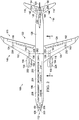
- aircraft 100 has wing 102 and wing 104 attached to fuselage 106.
- Aircraft 100 also includes engine 108 attached to wing 102 and engine 110 attached to wing 104.
- Fuselage 106 has nose section 112 and tail section 114. Nose section 112 is the forward part of aircraft 100, while tail section 114 is the aft part of aircraft 100. Horizontal stabilizer 116, horizontal stabilizer 118, and vertical stabilizer 120 are attached to tail section 114 of fuselage 106.
- Aircraft 100 is an example of an aircraft in which ice detection system 122 may be implemented in accordance with an illustrative embodiment.
- ice detection system 122 comprises sensors 124 on surface 126 of aircraft 100.
- sensors 124 include sensors 128, 130, 132, 134, 136, 138, 140, 142, 144, and 146. These sensors form first group of sensors 148 in sensors 124 for ice detection system 122.
- sensors 124 also include sensors 150, 152, 154, 156, 158, 160, 162, 164, 166, and 168. These sensors form second group of sensors 170 in sensors 124 for ice detection system 122. In the illustrative examples, sensors 124 may detect when ice is formed on the sensors.
- first group of sensors 148 is in a first group of locations on surface 126 of aircraft 100.
- First group of sensors 148 is configured to detect a first type of icing condition for aircraft 100.
- Second group of sensors 170 is in a second group of locations on surface 126 of aircraft 100. Second group of sensors 170 in the second locations is configured to detect a second type of icing condition for aircraft 100.
- these icing conditions may occur at different altitudes and temperatures that cause the formation of ice on aircraft 100.
- icing conditions may be present at an altitude from about sea level to about 30,000 feet when the temperature is from about -40 degrees Celsius to about 0 degrees Celsius.
- other altitudes and temperatures may be present at which ice may be formed from water that contacts surface 126 of aircraft 100.
- Icing conditions also may be present when the liquid water content in the drops is from about 0.4 to about 2.8 grams/cubic meter at the altitude and temperature range described above.
- the first type of icing condition and the second type of icing condition are caused by drops of water of different sizes.
- the altitude, temperature, and liquid water content ranges may be the same, one difference between the first and second types of icing conditions is the drop size.
- the first type of icing condition may be present when the size of the drops is from about 0.00465 millimeters in diameter to about 0.111 millimeters in diameter. Drops with these sizes may be referred to as normal drops.
- the second type of icing condition may be present when the size of the drops includes drops that have a diameter greater than about 0.111 millimeters. Drops having a size greater than about 0.111 millimeters may be referred to as large drops and, in particular, may be called supercooled large drops under the altitude, temperature, and liquid water content conditions described above. For example, the drops may have a diameter of a range from about 0.112 millimeters to about 2.2 millimeters.
- the second type of icing condition may include drops that are 0.111 millimeters or less when drops greater than 0.111 millimeters are present.
- first group of sensors 148 in the first group of locations may be configured to detect ice formed by drops of water in a first number of sizes.
- Second group of sensors 170 in the second group of locations is configured to detect ice formed by drops of water having a second number of sizes.
- the first number of sizes is smaller than the second number of sizes.
- the first number of sizes may be from about 0.00465 millimeters in diameter to about 0.111 millimeters in diameter.
- the second number of sizes may be from about 0.112 millimeters to about 2.2 millimeters in diameter.
- the second number of sizes of the drops of water may be drops of water that are considered to be drops of supercooled water. These drops of supercooled water may be supercooled large drops (SLD).
- First group of sensors 148 is configured to detect drops of water that are not supercooled large drops in these illustrative examples.
- the type of icing condition detected by sensors 124 is based on the locations for sensors 124 on surface 126 of aircraft 100 in these illustrative examples.
- the first type of icing condition may be referred to as a normal icing condition.
- the second type of icing condition may be referred to as a supercooled large drop icing condition.
- sensors 124 are depicted as flush-mounted sensors. In other words, sensors 124 are substantially flush or planar with surface 126 of aircraft 100. Sensors 124 may be implemented using all of the same type of sensors or different types of sensors. Further, other numbers of sensors 124 and locations of sensors 124 may be used in addition to or in place of those illustrated for aircraft 100 in Figure 1 .
- the different illustrative embodiments are not limited to the conditions and sizes depicted.
- other altitudes and drop sizes may be used to define when drops of water are present for the first icing condition and the second icing condition.
- Figure 1 illustrates embodiments using a twin-engine aircraft for example
- the illustrative embodiments recognize and take into account that the information contained is also applicable to aircraft with different numbers of engines.
- the illustrative example depicts aircraft 100 as a commercial aircraft.
- the different illustrative embodiments may be applied to other types of aircraft, such as military aircraft.
- ice detection system 122 further comprises processor unit 200.
- Processor unit 200 is a hardware device configured to perform operations with respect to detecting icing conditions for aircraft 100. These operations may be implemented in software, hardware, or a combination of the two.
- processor unit 200 is connected to sensors 124.
- sensors 124 generate data 202.
- Data 202 may indicate whether sensors 124 detect the formation of ice on surface 126 of aircraft 100. Ice is detected by sensors 124 when ice forms on one or more of sensors 124. Sensors 124 send data 202 to processor unit 200.
- processor unit 200 is configured to monitor the data from first group of sensors 148 and second group of sensors 170. Further, processor unit 200 is configured to perform an action in response to the data indicating a presence of one of the icing conditions.
- the particular type of icing condition detected depends on which group of sensors generating data indicates a presence of ice. In other words, the first icing condition, the second icing condition, or both the first icing condition and the second icing condition may be present depending on the data generated by sensors 124.
- the action may include at least one of generating an alert, generating a log entry, activating anti-icing system 204, sending a report, and other suitable actions.
- the phrase "at least one of”, when used with a list of items, means different combinations of one or more of the listed items may be used and only one of each item in the list may be needed.
- "at least one of item A, item B, and item C" may include, without limitation, item A, or item A and item B. This example also may include item A, item B, and item C, or item B and item C.
- the alert may be generated on flight deck interface 206 for aircraft 100.
- Flight deck interface 206 is a display system located in the flight deck of aircraft 100.
- the display system comprises a number of displays on which information may be displayed to operators. These displays are hardware devices in the illustrative examples.
- a "number”, when used with reference to items, means one or more items.
- “a number of displays” is one or more displays.
- the number of displays may include, for example, without limitation, a primary flight display, a navigation display, and other suitable types of displays.
- Flight management system 208 is a computer system in aircraft 100. This computer system may be comprised of a number of computers. When more than one computer is present in the computer system, those computers may be in communication with each other using a communications media, such as a local area network.
- Processor unit 200 may send a report to flight management system 208.
- the report may be sent to a remote location in addition to or in place of sending the report to flight management system 208.
- the report may include an indication of what type of icing condition or conditions is present. This report also may include a location of the sensor or sensors detecting the icing condition.
- Anti-icing system 204 may be implemented using any currently available anti-icing system.
- Anti-icing system 204 may employ different types of mechanisms to remove or prevent the formation of ice on surface 126 of aircraft 100.
- anti-icing system 204 may employ mechanical systems, chemical systems, infrared heating systems, and other types of systems to remove ice, prevent the formation of ice, or both on surface 126 of aircraft 100.
- sensors 124 may be configured in ice detection assemblies.
- sensors 124 may be grouped as ice detection assemblies 220, 222, 224, 226, 228, 230, 232, 234, 236, and 238.
- Each sensor in an ice detection assembly may be configured to detect a particular type of icing condition. This type of grouping of sensors 124 may be used in selecting locations for sensors 124.
- sensors 124 may not be grouped in ice detection assemblies.
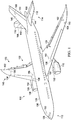
- airfoil 300 is wing 104 seen taken along lines 3-3 in Figure 2 .
- a flow of drops 301 with respect to airfoil 300 is illustrated. Locations where drops 301 collide with surface 302 are depicted in this illustrative example.
- sensor 138 and sensor 160 may be configured as ice detection assembly 230 on surface 302.
- sensor 138 is a first sensor located in first location 304 while sensor 160 is a second sensor located in second location 306.
- first location 304 is located in first region 308 and second location 306 is located in second region 310. As depicted, first region 308 is further forward on airfoil 300 than second region 310.
- first region 308 is comprised of a number of locations. This number of locations may be contiguous or non-contiguous with each other depending on the particular implementation. In this example, these locations are all contiguous.
- First region 308 is a region in which first drops 312 collide with surface 302 of airfoil 300 for aircraft 100.
- Second region 310 is also a number of locations that may be contiguous or non-contiguous with each other. In this example, these locations are non-contiguous. For example, a first portion of the number of locations may be in section 314, while a second portion of the number of locations may be in section 316. Second region 310 is a region in which second drops 318 collide with surface 302 of airfoil 300 for aircraft 100. First drops 312 collide with surface 302 in first region 308 when a first type of icing condition is present. Second drops 318 collide with surface 302 in second region 310 when a second type of icing condition is present. In these illustrative examples, first region 308 is further forward on airfoil 300 as compared to second region 310.
- sensor 138 in first location 304 is configured to detect the formation of ice when a first type of icing condition is present while sensor 160 in second location 306 is configured to detect the formation of ice when a second type of icing condition is present. In some cases, both types of icing conditions may be present at the same time.
- first drops 312 and second drops 318 are supercooled drops of water. These drops of water may be rain drops.
- the drops may have sizes ranging from about 0.00465 millimeters to about 2.2 millimeters in average diameter.
- normal drops are drops of water typically with sizes less than 0.111 millimeters in average diameter. These drops may freeze when colliding with first region 308 of surface 302 of airfoil 300. Drops of water in freezing drizzle drops may have a diameter that is less than about 0.5 millimeters. These drops may freeze when colliding with second region 310 of surface 302 of airfoil 300. Drops of freezing rain may have a diameter that is up to about 2.2 millimeters. These drops may freeze when colliding even further aft on second region 310 of surface 302 of airfoil 300.
- freezing drizzle is drizzle that may freeze on contact with surface 302 of airfoil 300.
- Freezing drizzle may have a diameter that is less than about 0.5 millimeters.
- Freezing rain is rain that may freeze when colliding with surface 302 of airfoil 300 and may have a diameter that is up to about 2.2 millimeters.
- Drops of water may be supercooled in various environments, such as in stratiform and in cumulous clouds. However, supercooled large drops typically only form in cumulous clouds.
- first drops 312 may be, for example, normal supercooled drops.
- Normal supercooled drops are drops of supercooled water that may have a diameter from about 0.00465 millimeters to about 0.111 millimeters.
- second drops 318 may be supercooled large drops. These drops may have a diameter with a size from about 0.112 millimeters to about 2.2 millimeters.
- first drops 312 and second drops 318 result in first drops 312 and second drops 318 colliding with surface 302 of airfoil 300 in different locations.
- the locations for the different drops are defined by first region 308 and second region 310.
- sensor 138 placement of sensor 138 is selected such that sensor 138 will detect a first type of icing condition caused by first drops 312.
- Sensor 160 is in second location 306 and is configured to detect a second type of icing condition caused by second drops 318 in these illustrative examples.
- the placement of sensor 138 and sensor 160 on surface 302 of airfoil 300 may be selected to detect different types of icing conditions. The location selected may depend on the configuration of airfoil 300.
- aircraft 100 is shown in the form of an airplane. Of course, aircraft 100 may take other forms. For example, without limitation, aircraft 100 also may take the form of a helicopter. Also, although aircraft 100 is illustrated as a commercial aircraft, the different illustrative embodiments may be applied to military aircraft and other types of aircraft depending on the particular implementation. For example, aircraft 100 also may be applied to an aircraft that may fly in the air as well as enter outer space, although icing conditions do not exist at altitudes that are considered outer space.
- sensors 124 are shown as grouped into ice detection assemblies, other illustrative embodiments may not employ ice detection assemblies. In other words, groupings of sensors into assemblies may not be used, depending on the particular implementation.
- processor unit 200 may be considered part of flight management system 208 instead of a separate component in the illustrative examples.
- sensors may be used other than those illustrated for aircraft 100.
- the number of sensors used may depend on the particular type of aircraft.
- the number of sensors and their locations may change depending on the size and configuration of airfoils on aircraft 100.
- the sensors may all be of the same type of sensors or different types of sensors.
- sensors 124 may be implemented using a sensor configured to detect a presence or formation of ice in these illustrative examples.
- Design environment 400 may be used to design an ice detection system for an aircraft in which the ice detection system is configured to detect a number of types of icing conditions.
- designer 402 may be implemented to generate ice detection system design 404 for ice detection system 406.
- Ice detection system 406 may be, for example, without limitation, ice detection system 122 in Figure 1 .
- designer 402 may be implemented using software, hardware, or a combination of the two.
- designer 402 may be implemented in computer system 408.
- Computer system 408 comprises a number of computers. When more than one computer is present in computer system 408, those computers may be in communication with each other. This communication may be facilitated using a communications medium, such as a network.
- designer 402 When designer 402 is implemented using software, designer 402 may take the form of program code that is configured to run on one or more computers. When hardware is employed, the hardware may include circuits that operate to perform the operations in designer 402.
- the hardware may take the form of a circuit system, an integrated circuit, an application specific integrated circuit (ASIC), a programmable logic device, or some other suitable type of hardware configured to perform a number of operations.
- ASIC application specific integrated circuit
- the device is configured to perform the number of operations.
- the device may be reconfigured at a later time or may be permanently configured to perform the number of operations.
- programmable logic devices include, for example, a programmable logic array, a programmable array logic, a field programmable logic array, a field programmable gate array, and other suitable hardware devices.
- the processes may be implemented in organic components integrated with inorganic components and/or may be comprised entirely of organic components excluding a human being.
- ice detection system design 404 may be generated using aircraft design 410 for aircraft 412.
- aircraft design 410 may be an input to designer 402 that is used to generate ice detection system 406.
- parameters 414 in aircraft design 410 for components 416 in aircraft 412 may be used to generate parameters 418 for ice detection system 406 in ice detection system design 404.
- Aircraft 412 may be, for example, aircraft 100 in Figure 1 .
- parameters 418 in ice detection system design 404 are for components 420 in ice detection system 406.
- components 420 in ice detection system 406 include processor unit 422 and sensor system 424.
- Sensor system 424 comprises sensors 426.
- Sensors 426 include first group of sensors 428 and second group of sensors 430.
- parameters 418 include locations 432 for sensors 426 in sensor system 424.
- locations 432 are locations on surface 434 of aircraft 412. Locations 432 may be defined using coordinates for aircraft 412.
- locations 432 include first group of locations 436 and second group of locations 438.
- First group of locations 436 is for first group of sensors 428.
- Second group of locations 438 is for second group of sensors 430.
- first group of sensors 428 and second group of sensors 430 may be arranged in ice detection assemblies 440 in which a first sensor in first group of sensors 428 and a second sensor in second group of sensors 430 are in an ice detection assembly in ice detection assemblies 440.
- Simulation 442 may be performed by computer system 408 to identify locations 432 for sensors 426.
- simulation 442 may simulate drops 444 for icing conditions 446.
- simulation 442 may be performed to identify locations 448 on surface 434 of aircraft 412 where drops 444 will collide with surface 434 of aircraft 412.
- drops 444 include first drops 450 and second drops 452.
- simulation 442 may be used to identify first region 454 in which first drops 450 will collide with surface 434 and second region 456 in which second drops 452 will collide with surface 434 for different structures on aircraft 412.
- the identification of locations 448 in simulation 442 may be used to identify locations 432 for sensors 426.
- first group of locations 436 is selected such that first drops 450 in drops 444 for first type of icing condition 458 in icing conditions 446 collide with surface 434 in first group of locations 436.
- Second group of locations 438 is selected such that second drops 452 in drops 444 for second type of icing condition 460 in icing conditions 446 collide with surface 434 of aircraft 412 in second group of locations 438.
- first drops 450 for first type of icing condition 458 may be normal supercooled drops.
- Second drops 452 for second type of icing condition 460 may be supercooled large drops in these illustrative examples.
- first group of locations 436 may be within first region 454 on surface 434 of structure 462 in structures 464 in aircraft 412.
- Second group of locations 438 may be located in second region 456 on surface 434 of structure 462.
- structure 462 in aircraft 412 may take the form of airfoil 466, fuselage 468, engine housing 470, engine inlet 471, and other suitable types of structures on aircraft 412.
- simulation 442 also may be used to select the number of sensors within sensors 426 in addition to locations 432 for sensors 426. Also, simulation 442 may be used to determine number of types of sensors 472 that may be used to implement sensors 426 in sensor system 424.
- design environment 400 in Figure 4 is not meant to imply physical or architectural limitations the manner in which an illustrative embodiment may be implemented. Other components in addition to and/or in place of the ones illustrated may be used. Some components may be unnecessary. Also, the blocks are presented to illustrate some functional components. One or more of these blocks may be combined, divided, or combined and divided into different blocks when implemented in an illustrative embodiment.
- ice detection system design 404 may be used to identify additional locations in locations 432 for sensors 426 to detect one or more additional types of icing conditions in addition to first type of icing condition 458 and second type of icing condition 460.
- ice detection system design 404 may already include first group of sensors 428 in first group of locations 436. Ice detection system design 404 may be modified to identify second group of locations 438 for second group of sensors 430. In this manner, designer 402 may be used to identify modifications to existing ice detection systems in these illustrative examples. In still other illustrative examples, ice detection system design 404 may be part of aircraft design 410 instead of a separate design.
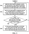
- FIG. 5 an illustration of a flowchart of a process for detecting icing conditions for an aircraft is depicted in accordance with an illustrative embodiment.
- the process illustrated in Figure 5 may be implemented in an ice detection system such as ice detection system 406 as specified by ice detection system design 404 in Figure 4 . Further, the process may be implemented in ice detection system 122 for aircraft 100 in Figure 1 . In particular, one or more operations performed in this flowchart may be implemented using processor unit 200 in Figure 2 .
- the process begins by monitoring a first group of sensors located at a first group of locations on the aircraft for first data indicating a first type of icing condition in the icing conditions for the aircraft (operation 500 ).
- the first group of sensors in operation 500 may be first group of sensors 148 in ice detection system 122 in Figure 1 .
- the process then monitors a second group of sensors located at a second group of locations on the aircraft for second data indicating a second type of icing condition for the aircraft (operation 502 ).
- the second group of sensors in operation 502 may be second group of sensors 170 in ice detection system 122 in Figure 1 .
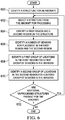
- FIG. 6 an illustration of a flowchart of a process for designing an ice detection system is depicted in accordance with an illustrative embodiment.
- the process illustrated in Figure 6 may be implemented in design environment 400 in Figure 4 .
- the process may be implemented using designer 402 in Figure 4 .
- the process begins by identifying a structure for an aircraft (operation 600 ). These structures may be any structure on which ice may form when one or more types of icing conditions are present. The process then selects a structure from the aircraft for processing (operation 602 ).
- the process then identifies a first region and a second region on the structure (operation 604 ).
- the first region is a region in which first drops for a first type of icing condition collide with the surface of the aircraft.
- the second region is a region in which second drops for a second type of icing condition collide with the surface of the aircraft.
- the process then identifies a number of sensors for placement in the first region and the second region (operation 606 ). In some cases, sensors may be absent from one region on the structure depending on the implementation.
- the process then identifies a first group of locations in the first region for a first group of sensors in the sensors (operation 608 ). The process then identifies a second group of locations in the second region for a second group of sensors in the sensors (operation 610 ). A determination is made as to whether additional unprocessed structures are present for the aircraft (operation 612 ). If additional unprocessed structures are present, the process returns to operation 602 as described above. Otherwise, the process terminates. When the process is completed, the design for the ice detection system may be finished and ready for implementation.
- each block in the flowcharts or block diagrams may represent a module, segment, or portion of computer usable or readable program code, which comprises one or more executable instructions for implementing the specified function or functions.
- the function or functions noted in the block may occur out of the order noted in the figures. For example, in some cases, two blocks shown in succession may be executed substantially concurrently, or the blocks may sometimes be executed in the reverse order, depending upon the functionality involved.
- Data processing system 700 may be used to implement flight management system 208 in Figure 2 , computer system 408 in Figure 4 , and other computers that may be used in different illustrative embodiments.
- data processing system 700 includes communications framework 702, which provides communications between processor unit 704, memory 706, persistent storage 708, communications unit 710, input/output (I/O) unit 712, and display 714.
- communications framework 702 may take the form of a bus system.
- Processor unit 704 serves to execute instructions for software that may be loaded into memory 706.
- Processor unit 704 may be a number of processors, a multi-processor core, or some other type of processor, depending on the particular implementation.
- processor unit 704 is an example of a processor unit that may be used to implement processor unit 200 in Figure 2 .
- Memory 706 and persistent storage 708 are examples of storage devices 716.
- a storage device is any piece of hardware that is capable of storing information such as, for example, without limitation, data, program code in functional form, and other suitable information either on a temporary basis or a permanent basis.
- Storage devices 716 also may be referred to as computer readable storage devices in these illustrative examples.
- Memory 706, in these examples, may be, for example, a random access memory or any other suitable volatile or nonvolatile storage device.
- Persistent storage 708 may take various forms, depending on the particular implementation.
- persistent storage 708 may contain one or more components or devices.
- persistent storage 708 may be a hard drive, a flash memory, a rewritable optical disk, a rewritable magnetic tape, or some combination of the above.
- the media used by persistent storage 708 also may be removable.
- a removable hard drive may be used for persistent storage 708.
- Communications unit 710 in these illustrative examples, provides for communications with other data processing systems or devices.
- communications unit 710 is a network interface card.
- Input/output unit 712 allows for input and output of data with other devices that may be connected to data processing system 700.
- input/output unit 712 may provide a connection for user input through a keyboard, a mouse, and/or some other suitable input device. Further, input/output unit 712 may send output to a printer.
- Display 714 provides a mechanism to display information to a user.
- Instructions for the operating system, applications, and/or programs may be located in storage devices 716, which are in communication with processor unit 704 through communications framework 702.
- the processes of the different embodiments may be performed by processor unit 704 using computer-implemented instructions, which may be located in a memory, such as memory 706.
- program code computer usable program code
- computer readable program code that may be read and executed by a processor in processor unit 704.
- the program code in the different embodiments may be embodied on different physical or computer readable storage media, such as memory 706 or persistent storage 708.
- Program code 718 is located in a functional form on computer readable media 720 that is selectively removable and may be loaded onto or transferred to data processing system 700 for execution by processor unit 704.
- Program code 718 and computer readable media 720 form computer program product 722 in these illustrative examples.
- computer readable media 720 may be computer readable storage media 724 or computer readable signal media 726.
- computer readable storage media 724 is a physical or tangible storage device used to store program code 718 rather than a medium that propagates or transmits program code 718.
- program code 718 may be transferred to data processing system 700 using computer readable signal media 726.
- Computer readable signal media 726 may be, for example, a propagated data signal containing program code 718.
- Computer readable signal media 726 may be an electromagnetic signal, an optical signal, and/or any other suitable type of signal. These signals may be transmitted over communications links, such as wireless communications links, optical fiber cable, coaxial cable, a wire, and/or any other suitable type of communications link.
- the different components illustrated for data processing system 700 are not meant to provide physical or architectural limitations to the manner in which different embodiments may be implemented.
- the different illustrative embodiments may be implemented in a data processing system including components in addition to and/or in place of those illustrated for data processing system 700.
- Other components shown in Figure 7 can be varied from the illustrative examples shown.
- the different embodiments may be implemented using any hardware device or system capable of running program code 718.
- aircraft manufacturing and service method 800 may be described in the context of aircraft manufacturing and service method 800 as shown in Figure 8 and aircraft 900 as shown in Figure 9 .
- Figure 8 an illustration of an aircraft manufacturing and service method is depicted in accordance with an illustrative embodiment.
- aircraft manufacturing and service method 800 may include specification and design 802 of aircraft 900 in Figure 9 and material procurement 804.
- aircraft 900 in Figure 9 During production, component and subassembly manufacturing 806 and system integration 808 of aircraft 900 in Figure 9 takes place. Thereafter, aircraft 900 in Figure 9 may go through certification and delivery 810 in order to be placed in service 812. While in service 812 by a customer, aircraft 900 in Figure 9 is scheduled for routine maintenance and service 814, which may include modification, reconfiguration, refurbishment, and other maintenance or service.
- Each of the processes of aircraft manufacturing and service method 800 may be performed or carried out by a system integrator, a third party, and/or an operator.
- the operator may be a customer.
- a system integrator may include, without limitation, any number of aircraft manufacturers and major-system subcontractors
- a third party may include, without limitation, any number of vendors, subcontractors, and suppliers
- an operator may be an airline, a leasing company, a military entity, a service organization, and so on.
- aircraft 900 is produced by aircraft manufacturing and service method 800 in Figure 8 and may include airframe 902 with plurality of systems 904 and interior 906.
- systems 904 include one or more of propulsion system 908, electrical system 910, hydraulic system 912, environmental system 914, and ice detection system 916. Any number of other systems may be included.
- propulsion system 908 electrical system 910, hydraulic system 912, environmental system 914, and ice detection system 916. Any number of other systems may be included.
- propulsion system 908 electrical system 910
- hydraulic system 912 hydraulic system 912
- environmental system 914 environmental system
- ice detection system 916 any number of other systems may be included.
- an aerospace example is shown, different illustrative embodiments may be applied to other industries, such as the automotive industry.
- Apparatuses and methods embodied herein may be employed during at least one of the stages of aircraft manufacturing and service method 800 in Figure 8 .
- components or subassemblies produced in component and subassembly manufacturing 806 in Figure 8 may be fabricated or manufactured in a manner similar to components or subassemblies produced while aircraft 900 is in service 812 in Figure 8 .
- ice detection system 916 may be designed during specification and design 802. Components for ice detection system 916 may be manufactured during component and subassembly manufacturing 806. Ice detection system 916 may be installed in aircraft 900 during system integration 808. Ice detection system 916 may be used while aircraft 900 is in service 812.
- ice detection system 916 may be an existing ice detection system in aircraft 900. Upgrades, modifications, and other operations may be performed to modify ice detection system 916 on aircraft 900 to include features in accordance with an illustrative embodiment.
- an ice detection system 406 including: a first group of sensors 428 located in a first group of locations 436 on an aircraft 412, wherein the first group of sensors 428 in the first group of locations 436 is configured to detect a first type of icing condition 458 for the aircraft 412, and a second group of sensors 430 located in a second group of locations 438 on the aircraft 412, wherein the second group of sensors 430 in the second group of locations 438 is configured to detect a second type of icing condition 460 for the aircraft 412.
- the ice detection system 406 includes wherein the first group of sensors 428 and the second group of sensors 430 generate data 202 and further including: a processor unit 422 configured to monitor the data 202 from the first group of sensors 428 and the second group of sensors 430 and perform an action in response to the data 202 indicating a presence of at least one of the first type of icing condition 458 and the second type of icing condition 460.
- the ice detection system 406 includes wherein the first group of locations 436 is a first number of locations 448 in which first drops 450 for the first type of icing condition 458 collide with a surface 434 of the aircraft 412 and the second group of locations 438 is a second number of locations 432 in which second drops 452 for the second type of icing condition 460 collide with the surface 434 of the aircraft 412.
- the ice detection system 406 includes wherein the surface 434 is a surface 434 of an airfoil 466 for the aircraft 412 and wherein the first drops 450 collide with the surface 434 in a first region 454 on the surface 434 of the airfoil 466, the second drops 452 collide with the surface 434 in a second region 456 on the surface 434 of the airfoil 466, and the first region 454 is further forward on the airfoil 466 than the second region 456.
- the ice detection system 406 includes wherein the first type of icing condition 458 is caused by first drops 450 having a first number of sizes, the second type of icing condition 460 is caused by second drops 452 having a second number of sizes, and the first number of sizes is smaller than the second number of sizes.
- the ice detection system 406 includes wherein the second type of icing condition 460 is a supercooled large drop icing condition. In one example, the ice detection system 406 includes wherein the action is selected from at least one of generating an alert, generating a log entry, activating an anti-icing system 204, and sending a report. In yet another example, the ice detection system 406 includes wherein the first group of locations 436 and the second group of locations 438 are on a structure 462 for the aircraft 412 and the structure 462 is selected from one of an airfoil 466, a wing, a horizontal stabilizer, a vertical stabilizer, a fuselage 468, an engine inlet 471, and a nose portion 112 of the fuselage 468.
- the ice detection system 406 includes wherein a first sensor 138 in the first group of sensors 428 and a second sensor 160 in the second group of sensors 430 form a sensor pair, wherein the first sensor 138 is a forward sensor and the second sensor 160 is an aft sensor that is located in a location that is aft of the forward sensor.
- the ice detection system includes wherein sensors in the first group of sensors 428 and the second group of sensors 430 are configured to detect a presence of ice.
- the ice detection system 406 includes wherein the aircraft 412 is selected from one of a commercial aircraft, a military aircraft, an airplane, and a helicopter.
- an ice detection system 406 including: a group of sensors located in a group of locations on a surface 434 of an aircraft 412, wherein the group of sensors in the group of locations is configured to detect a supercooled large drop icing condition on the surface 434 of the aircraft 412; and a processor unit 422 configured to monitor data 202 from the group of sensors and perform an action in response to the data 202 indicating a presence of the supercooled large drop icing condition on the surface 434 of the aircraft 412.
- the ice detection system 406 includes wherein the group of sensors 430 is a second group of sensors and further including: a first group of sensors 428 configured to detect another type of icing condition on the surface 434 of the aircraft 412.
- the ice detection system 406 includes wherein the group of locations is a number of locations in which drops for the supercooled large drop icing condition collide with the surface 434 of the aircraft 412.
- the ice detection system 406 includes wherein the surface 434 is a surface 434 of an airfoil 466 for the aircraft 412 and wherein the drops collide with the surface 434 in a region on the surface 434 of the airfoil 466 that is further aft as compared to drops from another type of icing condition on the surface 434 of the airfoil 466.
- the ice detection system 406 includes wherein the drops have a diameter from about 0.112 millimeters to about 2.2 millimeters.
- the ice detection system 406 includes wherein the action is selected from at least one of generating an alert, generating a log entry, activating an anti-icing system 204, and sending a report.
- a method for detecting icing conditions for an aircraft 412 includes: monitoring a first group of sensors 428 located in a first group of locations 436 on the aircraft 412 for first data 202 indicating a first type of icing condition 458 in the icing conditions for the aircraft 412; monitoring a second group of sensors 430 located in a second group of locations 438 on the aircraft 412 for second data 202 indicating a second type of icing condition in the icing conditions 460 for the aircraft 412; and initiating an action in response to detecting at least one of the first type of icing condition 458 from the first data and the second type of icing condition 460 from the second data 202.
- the method further includes: responsive to detecting an icing condition from at least one of the first data (202) and the second data 202, identifying a location on the aircraft 212 in which the icing condition is detected.
- the method includes wherein initiating the action in response to detecting the at least one of the first type of icing condition 458 from the first data 202 and the second type of icing condition 460 from the second data 202 includes: initiating the action in response to detecting the at least one of the first type of icing condition 458 from the first data 202 and the second type of icing condition 460 from the second data 202, wherein the action is selected from at least one of generating an alert 204, generating a log entry, activating an anti-icing system, and sending a report.
- an illustrative embodiment provides a method and apparatus for identifying different types of icing conditions.
- an illustrative embodiment provides an ability to identify a first type of icing condition and a second type of icing condition.
- the first type of icing condition may be one typically encountered while the second type of icing condition may be a supercooled large drop icing condition.
- the ability to identify more than one type of icing condition may allow an aircraft to be certified for flight in different types of icing conditions under various regulations that may be present from government or other regulatory entities, such as the Federal Aviation Administration.
Landscapes
- Engineering & Computer Science (AREA)
- Aviation & Aerospace Engineering (AREA)
- Investigating Or Analysing Materials By Optical Means (AREA)
- Testing Of Devices, Machine Parts, Or Other Structures Thereof (AREA)
- Geophysics And Detection Of Objects (AREA)
- Traffic Control Systems (AREA)
- User Interface Of Digital Computer (AREA)
Claims (8)
- Aéronef (12) comprenant un système de détection de givre (406), le système de détection de givre (406) comprenant :un premier groupe de capteurs (428) placé à un premier groupe d'emplacements (436) sur un aéronef (412), le premier groupe de capteurs (428) au premier groupe d'emplacements (436) étant configuré pour détecter un premier type de condition de givrage (458) pour l'aéronef (412), le premier type de condition de givrage (458) consistant en une condition de givrage normal ; etun deuxième groupe de capteurs (430) placé à un deuxième groupe d'emplacements (438) sur l'aéronef (412), le deuxième groupe de capteurs (430) au deuxième groupe d'emplacements (438) étant configuré pour détecter un deuxième type de condition de givrage (460) pour l'aéronef (412), le deuxième type de condition de givrage (460) consistant en une condition de givrage de grosses gouttes surfondues ;le premier groupe de capteurs (428) et le deuxième groupe de capteurs (430) générant des données (202), et le système de détection de givre (406) comprenant en outre :une unité formant processeur (422) configurée pour surveiller les données (202) issues du premier groupe de capteurs (428) et du deuxième groupe de capteurs (430) et accomplir une action en réponse au fait que les données (202) indiquent une présence du premier type de condition de givrage (458) et/ou du deuxième type de condition de givrage (460) ;le premier type de condition de givrage (458) étant dû à des premières gouttes (450) présentant un premier nombre de tailles allant d'environ 0,00465 millimètre de diamètre à environ 0,111 millimètre de diamètre, le deuxième type de condition de givrage (460) étant dû à des deuxièmes gouttes (452) présentant un deuxième nombre de tailles allant d'environ 0,112 millimètre de diamètre à environ 2,2 millimètres de diamètre, et le premier nombre de tailles étant inférieur au deuxième nombre de tailles ;l'action consistant en la génération d'une alerte (204),le premier groupe d'emplacements (436) consistant en un premier nombre d'emplacements (448) auxquels des premières gouttes (450) pour le premier type de condition de givrage (458) entrent en collision avec une surface (434) de l'aéronef (412) et le deuxième groupe d'emplacements (438) consistant en un deuxième nombre d'emplacements (432) auxquels des deuxièmes gouttes (452) pour le deuxième type de condition de givrage (46) entrent en collision avec la surface (434) de l'aéronef (412),la surface (434) consistant en une surface (434) d'un profil aérodynamique (466) pour l'aéronef (412), et les premières gouttes (450) entrant en collision avec la surface (434) dans une première région (454) sur la surface (434) du profil aérodynamique (466), les deuxièmes gouttes (452) entrant en collision avec la surface (434) dans une deuxième région (456) sur la surface (434) du profil aérodynamique (466), et la première région (454) étant plus en avant sur le profil aérodynamique (466) que la deuxième région (456), etles capteurs du premier groupe de capteurs (428) et du deuxième groupe de capteurs (430) étant montés à fleur de la surface (434) du profil aérodynamique (466) pour l'aéronef (412).
- Aéronef (12) selon la revendication 1, dans lequel l'action est en outre sélectionnée parmi au moins une des actions suivantes : la génération d'une entrée de journal, l'activation d'un système antigivrage (204) et l'envoi d'un rapport.
- Aéronef (12) selon la revendication 1 ou 2, dans lequel un premier capteur (138) dans le premier groupe de capteurs (428) et un deuxième capteur (160) dans le deuxième groupe de capteurs (430) forment une paire de capteurs, le premier capteur (138) consistant en un capteur avant et le deuxième capteur (160) consistant en un capteur arrière placé à un emplacement à l'arrière du capteur avant.
- Aéronef (12) selon la revendication 1, dans lequel des capteurs dans le premier groupe de capteurs (428) et le deuxième groupe de capteurs (430) sont configurés pour détecter une présence de givre.
- Aéronef (12) selon la revendication 1, dans lequel l'aéronef (412) est sélectionné parmi l'un des aéronefs suivants : un aéronef commercial, un aéronef militaire, un avion et un hélicoptère.
- Procédé de détection de conditions de givrage pour un aéronef (412), le procédé comprenant les étapes suivantes :surveillance d'un premier groupe de capteurs (428) placé à un premier groupe d'emplacements (436) sur l'aéronef (412) aux fins de déceler des premières données (202) indiquant un premier type de condition de givrage (458) dans les conditions de givrage (460) pour l'aéronef (412), le premier type de condition de givrage (458) consistant en une condition de givrage normal ;surveillance d'un deuxième groupe de capteurs (430) placé à un deuxième groupe d'emplacements (438) sur l'aéronef (412) aux fins de déceler des deuxièmes données (202) indiquant un deuxième type de condition de givrage dans les conditions de givrage (460) pour l'aéronef (412), le deuxième type de condition de givrage (460) consistant en une condition de givrage de grosses gouttes surfondues ; etle premier type de condition de givrage (458) étant dû à des premières gouttes (450) présentant un premier nombre de tailles allant d'environ 0,00465 millimètre de diamètre à environ 0,111 millimètre de diamètre, le deuxième type de condition de givrage (460) étant dû à des deuxièmes gouttes (452) présentant un deuxième nombre de tailles allant d'environ 0,112 millimètre de diamètre à environ 2,2 millimètres de diamètre, et le premier nombre de tailles étant inférieur au deuxième nombre de tailles,le premier groupe d'emplacements (436) consistant en un premier nombre d'emplacements (448) auxquels des premières gouttes (450) pour le premier type de condition de givrage (458) entrent en collision avec une surface (434) de l'aéronef (412) et le deuxième groupe d'emplacements (438) consistant en un deuxième nombre d'emplacements (432) auxquels des deuxièmes gouttes (452) pour le deuxième type de condition de givrage (46) entrent en collision avec la surface (434) de l'aéronef (412),et la surface (434) consistant en une surface (434) d'un profil aérodynamique (466) pour l'aéronef (412), et les premières gouttes (450) entrant en collision avec la surface (434) dans une première région (454) sur la surface (434) du profil aérodynamique (466), les deuxièmes gouttes (452) entrant en collision avec la surface (434) dans une deuxième région (456) sur la surface (434) du profil aérodynamique (466), et la première région (454) étant plus en avant sur le profil aérodynamique (466) que la deuxième région (456), les capteurs du premier groupe de capteurs (428) et du deuxième groupe de capteurs (430) étant montés à fleur de la surface (434) du profil aérodynamique (466) pour l'aéronef (412) ;déclenchement d'une action en réponse à la détection du premier type de condition de givrage (458) à partir des premières données et/ou du deuxième type de condition de givrage (460) à partir des deuxièmes données (202), l'action consistant en la génération d'une alerte (204).
- Procédé selon la revendication 6, comprenant en outre l'étape suivante :
en réponse à la détection d'une condition de givrage à partir des premières données (202) et/ou des deuxièmes données (202), identification d'un emplacement sur l'aéronef (212) auquel la condition de givrage est détectée. - Procédé selon l'une quelconque des revendications 6 ou 7, dans lequel l'étape de déclenchement de l'action en réponse à la détection du premier type de condition de givrage (458) à partir des premières données (202) et/ou du deuxième type de condition de givrage (460) à partir des deuxièmes données (202) comprend l'étape suivante :
déclenchement d'une action supplémentaire en réponse à la détection du premier type de condition de givrage (458) à partir des premières données (202) et/ou du deuxième type de condition de givrage (460) à partir des deuxièmes données (202), l'action supplémentaire étant sélectionnée parmi au moins une des actions suivantes : la génération d'une entrée de journal, l'activation d'un système antigivrage et l'envoi d'un rapport.
Applications Claiming Priority (2)
| Application Number | Priority Date | Filing Date | Title |
|---|---|---|---|
| US13/344,144 US8907798B2 (en) | 2012-01-05 | 2012-01-05 | Supercooled large drop icing condition detection system |
| PCT/US2012/066515 WO2013103453A1 (fr) | 2012-01-05 | 2012-11-26 | Système de détection d'une condition de givrage à grosses gouttes surfondues |
Publications (2)
| Publication Number | Publication Date |
|---|---|
| EP2800690A1 EP2800690A1 (fr) | 2014-11-12 |
| EP2800690B1 true EP2800690B1 (fr) | 2018-08-08 |
Family
ID=47604046
Family Applications (1)
| Application Number | Title | Priority Date | Filing Date |
|---|---|---|---|
| EP12818681.4A Active EP2800690B1 (fr) | 2012-01-05 | 2012-11-26 | Système de détection d'une condition de givrage à grosses gouttes surfondues |
Country Status (8)
| Country | Link |
|---|---|
| US (1) | US8907798B2 (fr) |
| EP (1) | EP2800690B1 (fr) |
| JP (1) | JP6449019B2 (fr) |
| CN (1) | CN104039650B (fr) |
| AU (1) | AU2012363760B2 (fr) |
| BR (1) | BR112014016525B1 (fr) |
| CA (1) | CA2851393C (fr) |
| WO (1) | WO2013103453A1 (fr) |
Families Citing this family (16)
| Publication number | Priority date | Publication date | Assignee | Title |
|---|---|---|---|---|
| EP2800691B1 (fr) * | 2012-01-06 | 2020-03-04 | Instrumar Limited | Appareil et procédé de surveillance de l'accumulation de matière sur une surface d'aéronef |
| US9612163B2 (en) * | 2013-10-10 | 2017-04-04 | The Boeing Company | Methods and apparatus for detecting ice formation on aircraft |
| US9242735B1 (en) | 2014-08-28 | 2016-01-26 | The Boeing Company | Detecting inflight icing conditions on aircraft |
| CN104268399B (zh) * | 2014-09-24 | 2017-03-15 | 空气动力学国家重点实验室 | 过冷大水滴条件下结冰风洞试验中模型参数的计算方法 |
| US20170283077A1 (en) * | 2016-04-01 | 2017-10-05 | Goodrich Corporation | Pneumatic de-icer with sensor for supercooled large droplet icing detection |
| CN105865100B (zh) * | 2016-04-05 | 2018-03-16 | 北京航空航天大学 | 一种样件弹射式过冷液滴撞击微观观测系统 |
| DE102016111902A1 (de) * | 2016-06-29 | 2018-01-04 | Deutsches Zentrum für Luft- und Raumfahrt e.V. | Verfahren und Assistenzsystem zur Detektion einer Flugleistungsdegradierung |
| US10071808B1 (en) * | 2017-05-18 | 2018-09-11 | The Boeing Company | Aircraft icing conditions detection systems and methods |
| IL253739B (en) | 2017-07-31 | 2021-01-31 | Israel Aerospace Ind Ltd | Baldness detector |
| US20190039742A1 (en) * | 2017-08-01 | 2019-02-07 | Honeywell International Inc. | Managing response to icing threat |
| KR102163195B1 (ko) * | 2019-01-17 | 2020-10-08 | 경상대학교산학협력단 | 항공기 방·제빙 시스템 및 이를 이용한 방·제빙 방법 |
| KR102315288B1 (ko) * | 2020-01-29 | 2021-10-20 | 경상국립대학교산학협력단 | 항공기 날개의 방·제빙 시스템 및 이를 이용한 방·제빙 방법 |
| CN111912380B (zh) * | 2020-07-27 | 2022-12-06 | 杭州乾博科技有限公司 | 一种水表冰冻程度计算方法及系统 |
| US11685534B2 (en) | 2020-08-10 | 2023-06-27 | Lockheed Martin Corporation | System and method for determining the real-time effect of ice accumulation on aircraft surfaces on angle of attack during flight |
| CN111976996B (zh) * | 2020-08-26 | 2022-02-18 | 四川大学 | 一种无人机机翼分区防冰方法 |
| CN112678189B (zh) * | 2021-03-09 | 2021-06-04 | 中国空气动力研究与发展中心低速空气动力研究所 | 一种改进的结冰传感器安装位置确定方法 |
Family Cites Families (19)
| Publication number | Priority date | Publication date | Assignee | Title |
|---|---|---|---|---|
| US5248116A (en) * | 1992-02-07 | 1993-09-28 | The B. F. Goodrich Company | Airfoil with integral de-icer using overlapped tubes |
| US5354015A (en) | 1993-08-10 | 1994-10-11 | Meador Robert H | System for warning the flight crew on board an aircraft of pre-flight aircraft icing |
| US5474261A (en) | 1993-09-20 | 1995-12-12 | Raton Technology Research, Inc. | Ice detection apparatus for transportation safety |
| US5484121A (en) | 1993-11-12 | 1996-01-16 | Padawer; Jacques | Icing detector for aircraft surfaces |
| US6759962B2 (en) | 2001-04-25 | 2004-07-06 | Rosemount Aerospace Inc. | Inflight ice detector to distinguish supercooled large droplet (SLD) icing |
| CA2452623A1 (fr) * | 2001-06-29 | 2003-01-09 | Rosemount Aerospace Inc. | Detecteur de givre permettant de detecter de grosses gouttelettes surfondues |
| US6731225B2 (en) | 2002-02-14 | 2004-05-04 | Lockheed Martin Corporation | Method and apparatus for detecting and measuring thickness of ice on aircraft |
| US7175136B2 (en) | 2003-04-16 | 2007-02-13 | The Boeing Company | Method and apparatus for detecting conditions conducive to ice formation |
| US7312713B2 (en) * | 2004-12-17 | 2007-12-25 | Research Foundation Of The City University Of New York | Methods and systems for detection of ice formation on surfaces |
| ITTO20060400A1 (it) | 2006-05-31 | 2007-12-01 | Lorenzo Battisti | Metodo e sistema per la rilevazione di pericolo di formazione di ghiaccio su superfici aerodinamiche |
| US20080283661A1 (en) * | 2006-08-02 | 2008-11-20 | Bruce Hyndman Henley | Remote Controlled Mobile Platform |
| US7564373B2 (en) * | 2006-11-30 | 2009-07-21 | Safe Flight Instrument Corporation | System and method for detecting ice formation on an aircraft |
| EP2117926B1 (fr) | 2007-01-10 | 2018-12-26 | Sikorsky Aircraft Corporation | Dispositif de mesure du taux de givrage à aspiration virtuelle |
| US7439877B1 (en) * | 2007-05-18 | 2008-10-21 | Philip Onni Jarvinen | Total impedance and complex dielectric property ice detection system |
| US20100123044A1 (en) | 2008-11-17 | 2010-05-20 | Botura Galdemir C | Aircraft Ice Protection System |
| US8144325B2 (en) | 2009-07-23 | 2012-03-27 | Rosemount Aerospace, Inc. | In-flight multiple field of view detector for supercooled airborne water droplets |
| ATE544678T1 (de) * | 2009-11-24 | 2012-02-15 | Agustawestland Spa | Luftfahrzeug mit einer vereisungsanzeige |
| CN201566837U (zh) * | 2009-12-29 | 2010-09-01 | 陕西飞机工业(集团)有限公司 | 飞机结冰传感器配置 |
| WO2012000384A1 (fr) * | 2010-07-02 | 2012-01-05 | 中国商用飞机有限责任公司 | Dispositif de détection pour détecter la formation de glace en utilisant une image et procédé de détection associé |
-
2012
- 2012-01-05 US US13/344,144 patent/US8907798B2/en active Active
- 2012-11-26 CN CN201280065812.3A patent/CN104039650B/zh active Active
- 2012-11-26 BR BR112014016525-4A patent/BR112014016525B1/pt active IP Right Grant
- 2012-11-26 EP EP12818681.4A patent/EP2800690B1/fr active Active
- 2012-11-26 JP JP2014551243A patent/JP6449019B2/ja active Active
- 2012-11-26 CA CA2851393A patent/CA2851393C/fr active Active
- 2012-11-26 WO PCT/US2012/066515 patent/WO2013103453A1/fr active Application Filing
- 2012-11-26 AU AU2012363760A patent/AU2012363760B2/en active Active
Non-Patent Citations (1)
| Title |
|---|
| None * |
Also Published As
| Publication number | Publication date |
|---|---|
| AU2012363760B2 (en) | 2016-05-26 |
| EP2800690A1 (fr) | 2014-11-12 |
| BR112014016525A8 (pt) | 2017-07-04 |
| BR112014016525B1 (pt) | 2022-02-15 |
| CA2851393C (fr) | 2016-04-26 |
| JP2015503487A (ja) | 2015-02-02 |
| US8907798B2 (en) | 2014-12-09 |
| CA2851393A1 (fr) | 2013-07-11 |
| JP6449019B2 (ja) | 2019-01-09 |
| WO2013103453A1 (fr) | 2013-07-11 |
| BR112014016525A2 (pt) | 2017-06-13 |
| AU2012363760A1 (en) | 2014-04-24 |
| US20130175396A1 (en) | 2013-07-11 |
| CN104039650A (zh) | 2014-09-10 |
| CN104039650B (zh) | 2017-07-04 |
Similar Documents
| Publication | Publication Date | Title |
|---|---|---|
| EP2800690B1 (fr) | Système de détection d'une condition de givrage à grosses gouttes surfondues | |
| EP2639158B1 (fr) | Système à laser pour la détection de conditions de givrage | |
| US10124901B2 (en) | Icing condition detection method | |
| EP2636599B1 (fr) | Système de détection d'état de givrage de goutte d'eau de grande taille en surfusion | |
| US9180972B2 (en) | Supercooled large drop icing condition detection system | |
| CN105383701B (zh) | 检测飞机上的飞行中结冰情况 | |
| EP3620380A1 (fr) | Systèmes de détection de glace pour aéronef et procédés associés | |
| Jackson et al. | Ice detection systems: a historical perspective |
Legal Events
| Date | Code | Title | Description |
|---|---|---|---|
| PUAI | Public reference made under article 153(3) epc to a published international application that has entered the european phase |
Free format text: ORIGINAL CODE: 0009012 |
|
| 17P | Request for examination filed |
Effective date: 20140805 |
|
| AK | Designated contracting states |
Kind code of ref document: A1 Designated state(s): AL AT BE BG CH CY CZ DE DK EE ES FI FR GB GR HR HU IE IS IT LI LT LU LV MC MK MT NL NO PL PT RO RS SE SI SK SM TR |
|
| DAX | Request for extension of the european patent (deleted) | ||
| 17Q | First examination report despatched |
Effective date: 20160219 |
|
| GRAP | Despatch of communication of intention to grant a patent |
Free format text: ORIGINAL CODE: EPIDOSNIGR1 |
|
| INTG | Intention to grant announced |
Effective date: 20180221 |
|
| RAP1 | Party data changed (applicant data changed or rights of an application transferred) |
Owner name: THE BOEING COMPANY |
|
| GRAS | Grant fee paid |
Free format text: ORIGINAL CODE: EPIDOSNIGR3 |
|
| GRAA | (expected) grant |
Free format text: ORIGINAL CODE: 0009210 |
|
| AK | Designated contracting states |
Kind code of ref document: B1 Designated state(s): AL AT BE BG CH CY CZ DE DK EE ES FI FR GB GR HR HU IE IS IT LI LT LU LV MC MK MT NL NO PL PT RO RS SE SI SK SM TR |
|
| REG | Reference to a national code |
Ref country code: GB Ref legal event code: FG4D |
|
| REG | Reference to a national code |
Ref country code: CH Ref legal event code: EP Ref country code: AT Ref legal event code: REF Ref document number: 1026681 Country of ref document: AT Kind code of ref document: T Effective date: 20180815 |
|
| REG | Reference to a national code |
Ref country code: IE Ref legal event code: FG4D |
|
| REG | Reference to a national code |
Ref country code: DE Ref legal event code: R096 Ref document number: 602012049602 Country of ref document: DE |
|
| REG | Reference to a national code |
Ref country code: NL Ref legal event code: MP Effective date: 20180808 |
|
| REG | Reference to a national code |
Ref country code: LT Ref legal event code: MG4D |
|
| REG | Reference to a national code |
Ref country code: AT Ref legal event code: MK05 Ref document number: 1026681 Country of ref document: AT Kind code of ref document: T Effective date: 20180808 |
|
| PG25 | Lapsed in a contracting state [announced via postgrant information from national office to epo] |
Ref country code: FI Free format text: LAPSE BECAUSE OF FAILURE TO SUBMIT A TRANSLATION OF THE DESCRIPTION OR TO PAY THE FEE WITHIN THE PRESCRIBED TIME-LIMIT Effective date: 20180808 Ref country code: PL Free format text: LAPSE BECAUSE OF FAILURE TO SUBMIT A TRANSLATION OF THE DESCRIPTION OR TO PAY THE FEE WITHIN THE PRESCRIBED TIME-LIMIT Effective date: 20180808 Ref country code: IS Free format text: LAPSE BECAUSE OF FAILURE TO SUBMIT A TRANSLATION OF THE DESCRIPTION OR TO PAY THE FEE WITHIN THE PRESCRIBED TIME-LIMIT Effective date: 20181208 Ref country code: NL Free format text: LAPSE BECAUSE OF FAILURE TO SUBMIT A TRANSLATION OF THE DESCRIPTION OR TO PAY THE FEE WITHIN THE PRESCRIBED TIME-LIMIT Effective date: 20180808 Ref country code: AT Free format text: LAPSE BECAUSE OF FAILURE TO SUBMIT A TRANSLATION OF THE DESCRIPTION OR TO PAY THE FEE WITHIN THE PRESCRIBED TIME-LIMIT Effective date: 20180808 Ref country code: LT Free format text: LAPSE BECAUSE OF FAILURE TO SUBMIT A TRANSLATION OF THE DESCRIPTION OR TO PAY THE FEE WITHIN THE PRESCRIBED TIME-LIMIT Effective date: 20180808 Ref country code: BG Free format text: LAPSE BECAUSE OF FAILURE TO SUBMIT A TRANSLATION OF THE DESCRIPTION OR TO PAY THE FEE WITHIN THE PRESCRIBED TIME-LIMIT Effective date: 20181108 Ref country code: GR Free format text: LAPSE BECAUSE OF FAILURE TO SUBMIT A TRANSLATION OF THE DESCRIPTION OR TO PAY THE FEE WITHIN THE PRESCRIBED TIME-LIMIT Effective date: 20181109 Ref country code: NO Free format text: LAPSE BECAUSE OF FAILURE TO SUBMIT A TRANSLATION OF THE DESCRIPTION OR TO PAY THE FEE WITHIN THE PRESCRIBED TIME-LIMIT Effective date: 20181108 Ref country code: RS Free format text: LAPSE BECAUSE OF FAILURE TO SUBMIT A TRANSLATION OF THE DESCRIPTION OR TO PAY THE FEE WITHIN THE PRESCRIBED TIME-LIMIT Effective date: 20180808 Ref country code: SE Free format text: LAPSE BECAUSE OF FAILURE TO SUBMIT A TRANSLATION OF THE DESCRIPTION OR TO PAY THE FEE WITHIN THE PRESCRIBED TIME-LIMIT Effective date: 20180808 |
|
| PG25 | Lapsed in a contracting state [announced via postgrant information from national office to epo] |
Ref country code: AL Free format text: LAPSE BECAUSE OF FAILURE TO SUBMIT A TRANSLATION OF THE DESCRIPTION OR TO PAY THE FEE WITHIN THE PRESCRIBED TIME-LIMIT Effective date: 20180808 Ref country code: LV Free format text: LAPSE BECAUSE OF FAILURE TO SUBMIT A TRANSLATION OF THE DESCRIPTION OR TO PAY THE FEE WITHIN THE PRESCRIBED TIME-LIMIT Effective date: 20180808 Ref country code: HR Free format text: LAPSE BECAUSE OF FAILURE TO SUBMIT A TRANSLATION OF THE DESCRIPTION OR TO PAY THE FEE WITHIN THE PRESCRIBED TIME-LIMIT Effective date: 20180808 |
|
| PG25 | Lapsed in a contracting state [announced via postgrant information from national office to epo] |
Ref country code: IT Free format text: LAPSE BECAUSE OF FAILURE TO SUBMIT A TRANSLATION OF THE DESCRIPTION OR TO PAY THE FEE WITHIN THE PRESCRIBED TIME-LIMIT Effective date: 20180808 Ref country code: EE Free format text: LAPSE BECAUSE OF FAILURE TO SUBMIT A TRANSLATION OF THE DESCRIPTION OR TO PAY THE FEE WITHIN THE PRESCRIBED TIME-LIMIT Effective date: 20180808 Ref country code: RO Free format text: LAPSE BECAUSE OF FAILURE TO SUBMIT A TRANSLATION OF THE DESCRIPTION OR TO PAY THE FEE WITHIN THE PRESCRIBED TIME-LIMIT Effective date: 20180808 Ref country code: ES Free format text: LAPSE BECAUSE OF FAILURE TO SUBMIT A TRANSLATION OF THE DESCRIPTION OR TO PAY THE FEE WITHIN THE PRESCRIBED TIME-LIMIT Effective date: 20180808 Ref country code: CZ Free format text: LAPSE BECAUSE OF FAILURE TO SUBMIT A TRANSLATION OF THE DESCRIPTION OR TO PAY THE FEE WITHIN THE PRESCRIBED TIME-LIMIT Effective date: 20180808 |
|
| REG | Reference to a national code |
Ref country code: DE Ref legal event code: R097 Ref document number: 602012049602 Country of ref document: DE |
|
| PG25 | Lapsed in a contracting state [announced via postgrant information from national office to epo] |
Ref country code: DK Free format text: LAPSE BECAUSE OF FAILURE TO SUBMIT A TRANSLATION OF THE DESCRIPTION OR TO PAY THE FEE WITHIN THE PRESCRIBED TIME-LIMIT Effective date: 20180808 Ref country code: SK Free format text: LAPSE BECAUSE OF FAILURE TO SUBMIT A TRANSLATION OF THE DESCRIPTION OR TO PAY THE FEE WITHIN THE PRESCRIBED TIME-LIMIT Effective date: 20180808 Ref country code: SM Free format text: LAPSE BECAUSE OF FAILURE TO SUBMIT A TRANSLATION OF THE DESCRIPTION OR TO PAY THE FEE WITHIN THE PRESCRIBED TIME-LIMIT Effective date: 20180808 |
|
| PLBE | No opposition filed within time limit |
Free format text: ORIGINAL CODE: 0009261 |
|
| STAA | Information on the status of an ep patent application or granted ep patent |
Free format text: STATUS: NO OPPOSITION FILED WITHIN TIME LIMIT |
|
| REG | Reference to a national code |
Ref country code: CH Ref legal event code: PL |
|
| 26N | No opposition filed |
Effective date: 20190509 |
|
| PG25 | Lapsed in a contracting state [announced via postgrant information from national office to epo] |
Ref country code: LU Free format text: LAPSE BECAUSE OF NON-PAYMENT OF DUE FEES Effective date: 20181126 Ref country code: MC Free format text: LAPSE BECAUSE OF FAILURE TO SUBMIT A TRANSLATION OF THE DESCRIPTION OR TO PAY THE FEE WITHIN THE PRESCRIBED TIME-LIMIT Effective date: 20180808 |
|
| REG | Reference to a national code |
Ref country code: BE Ref legal event code: MM Effective date: 20181130 |
|
| REG | Reference to a national code |
Ref country code: IE Ref legal event code: MM4A |
|
| PG25 | Lapsed in a contracting state [announced via postgrant information from national office to epo] |
Ref country code: LI Free format text: LAPSE BECAUSE OF NON-PAYMENT OF DUE FEES Effective date: 20181130 Ref country code: CH Free format text: LAPSE BECAUSE OF NON-PAYMENT OF DUE FEES Effective date: 20181130 Ref country code: SI Free format text: LAPSE BECAUSE OF FAILURE TO SUBMIT A TRANSLATION OF THE DESCRIPTION OR TO PAY THE FEE WITHIN THE PRESCRIBED TIME-LIMIT Effective date: 20180808 |
|
| PG25 | Lapsed in a contracting state [announced via postgrant information from national office to epo] |
Ref country code: IE Free format text: LAPSE BECAUSE OF NON-PAYMENT OF DUE FEES Effective date: 20181126 |
|
| PG25 | Lapsed in a contracting state [announced via postgrant information from national office to epo] |
Ref country code: BE Free format text: LAPSE BECAUSE OF NON-PAYMENT OF DUE FEES Effective date: 20181130 |
|
| PG25 | Lapsed in a contracting state [announced via postgrant information from national office to epo] |
Ref country code: MT Free format text: LAPSE BECAUSE OF NON-PAYMENT OF DUE FEES Effective date: 20181126 |
|
| PG25 | Lapsed in a contracting state [announced via postgrant information from national office to epo] |
Ref country code: TR Free format text: LAPSE BECAUSE OF FAILURE TO SUBMIT A TRANSLATION OF THE DESCRIPTION OR TO PAY THE FEE WITHIN THE PRESCRIBED TIME-LIMIT Effective date: 20180808 |
|
| PG25 | Lapsed in a contracting state [announced via postgrant information from national office to epo] |
Ref country code: PT Free format text: LAPSE BECAUSE OF FAILURE TO SUBMIT A TRANSLATION OF THE DESCRIPTION OR TO PAY THE FEE WITHIN THE PRESCRIBED TIME-LIMIT Effective date: 20180808 |
|
| PG25 | Lapsed in a contracting state [announced via postgrant information from national office to epo] |
Ref country code: HU Free format text: LAPSE BECAUSE OF FAILURE TO SUBMIT A TRANSLATION OF THE DESCRIPTION OR TO PAY THE FEE WITHIN THE PRESCRIBED TIME-LIMIT; INVALID AB INITIO Effective date: 20121126 Ref country code: MK Free format text: LAPSE BECAUSE OF NON-PAYMENT OF DUE FEES Effective date: 20180808 Ref country code: CY Free format text: LAPSE BECAUSE OF FAILURE TO SUBMIT A TRANSLATION OF THE DESCRIPTION OR TO PAY THE FEE WITHIN THE PRESCRIBED TIME-LIMIT Effective date: 20180808 |
|
| P01 | Opt-out of the competence of the unified patent court (upc) registered |
Effective date: 20230516 |
|
| PGFP | Annual fee paid to national office [announced via postgrant information from national office to epo] |
Ref country code: GB Payment date: 20231127 Year of fee payment: 12 |
|
| PGFP | Annual fee paid to national office [announced via postgrant information from national office to epo] |
Ref country code: FR Payment date: 20231127 Year of fee payment: 12 Ref country code: DE Payment date: 20231129 Year of fee payment: 12 |