EP2774841A1 - Vorrichtung zum Schutz eines Drehflügelflugzeugs gegen eine pyramidale Struktur zur Lastbeförderung - Google Patents
Vorrichtung zum Schutz eines Drehflügelflugzeugs gegen eine pyramidale Struktur zur Lastbeförderung Download PDFInfo
- Publication number
- EP2774841A1 EP2774841A1 EP20140000462 EP14000462A EP2774841A1 EP 2774841 A1 EP2774841 A1 EP 2774841A1 EP 20140000462 EP20140000462 EP 20140000462 EP 14000462 A EP14000462 A EP 14000462A EP 2774841 A1 EP2774841 A1 EP 2774841A1
- Authority
- EP
- European Patent Office
- Prior art keywords
- arms
- pair
- pyramidal structure
- fuselage
- protection plate
- Prior art date
- Legal status (The legal status is an assumption and is not a legal conclusion. Google has not performed a legal analysis and makes no representation as to the accuracy of the status listed.)
- Granted
Links
Images

Classifications
-
- B—PERFORMING OPERATIONS; TRANSPORTING
- B64—AIRCRAFT; AVIATION; COSMONAUTICS
- B64C—AEROPLANES; HELICOPTERS
- B64C7/00—Structures or fairings not otherwise provided for
-
- B—PERFORMING OPERATIONS; TRANSPORTING
- B64—AIRCRAFT; AVIATION; COSMONAUTICS
- B64C—AEROPLANES; HELICOPTERS
- B64C27/00—Rotorcraft; Rotors peculiar thereto
- B64C27/006—Safety devices
-
- B—PERFORMING OPERATIONS; TRANSPORTING
- B64—AIRCRAFT; AVIATION; COSMONAUTICS
- B64D—EQUIPMENT FOR FITTING IN OR TO AIRCRAFT; FLIGHT SUITS; PARACHUTES; ARRANGEMENT OR MOUNTING OF POWER PLANTS OR PROPULSION TRANSMISSIONS IN AIRCRAFT
- B64D1/00—Dropping, ejecting, releasing or receiving articles, liquids, or the like, in flight
- B64D1/02—Dropping, ejecting, or releasing articles
- B64D1/08—Dropping, ejecting, or releasing articles the articles being load-carrying devices
- B64D1/14—Absorbing landing shocks
-
- B—PERFORMING OPERATIONS; TRANSPORTING
- B64—AIRCRAFT; AVIATION; COSMONAUTICS
- B64D—EQUIPMENT FOR FITTING IN OR TO AIRCRAFT; FLIGHT SUITS; PARACHUTES; ARRANGEMENT OR MOUNTING OF POWER PLANTS OR PROPULSION TRANSMISSIONS IN AIRCRAFT
- B64D1/00—Dropping, ejecting, releasing or receiving articles, liquids, or the like, in flight
- B64D1/22—Taking-up articles from earth's surface
-
- B—PERFORMING OPERATIONS; TRANSPORTING
- B64—AIRCRAFT; AVIATION; COSMONAUTICS
- B64C—AEROPLANES; HELICOPTERS
- B64C27/00—Rotorcraft; Rotors peculiar thereto
- B64C27/04—Helicopters
Definitions
- the present invention relates to a protective device for protecting a rotorcraft against a load carrying pyramidal structure, a fastening system provided with said device and said structure, and a rotorcraft equipped with the fastening system.
- the invention relates to the method used.
- the technical field of the invention is therefore that of devices for attaching a load external to an aircraft, and in particular an aircraft equipped with a rotary wing.
- a rotorcraft has a fuselage carrying at least one lifting rotor, or even propulsion.
- the rotorcraft can then be provided with a removable attachment system to carry an external load.
- Such a fastening system may usually include a rotating hook or non-rotating fastener attached to the fuselage by a fixing means. A sling is then hooked to this hook-unloader to allow the carriage of external loads.
- the fixing system may in particular be a system called “cargo swing” in English, or more simply “swing”.
- a "swing" fastening system may include a pyramid structure.
- the pyramidal structure is provided with a quadrilateral frame and four arms, each arm extending from the frame to an apex.
- the pyramidal structure has a pair of two front arms and a pair of two rear arms.
- the terms “forward” and “backward” refer to the direction of travel of the aircraft.
- the pyramidal structure may have two long arms and two short arms, the vertex then not being placed in line with the intersection of the diagonals of the frame.
- the front arms represent the short arms
- the rear arms represent the long arms.
- the frame can be made using four tubes connected in pairs, each arm being for example fixed to the corners of the frame. This frame can also be obtained using four independent tubes, each tube extending between two adjacent arms.
- the fastening system can be rigid or articulated.
- the four arms can be linked to each other to form the top of the fastening system. The four arms are then secured to each other.
- the arms can be connected in pairs.
- the two front arms are secured by their upper ends
- the two rear arms being also secured by their upper ends.
- the upper ends of the front and rear arms are then articulated to the base of the top along an axis of rotation.
- the two front arms thus constitute a front assembly that can rotate relative to a rear assembly consisting of the two rear arms.
- the tubes constituting the frame of the pyramidal structure are then adapted to allow such relative rotation between the front and rear assemblies.
- a hook-shed is usually suspended at the top of the structure pyramid.
- the displacement of the hook-shedding device within the fastening system is restricted to the zone delimited by the frame of the pyramidal structure.
- the pyramidal structure is also suspended under a fuselage by four suspension cables for example.
- the "swing” fastening system is used in the aeronautical field with satisfaction.
- the pyramidal structure can prove to be aggressive in the event of a rotorcraft crash.
- the pyramidal structure comes into contact with the ground.
- the pyramidal structure may then perforate the fuselage, the shape of this pyramidal structure making it very resistant to crushing.
- the efforts required to crush the pyramidal structure are indeed very high.
- the pyramidal structure may not crash, and thus hit the fuselage and perforate.
- the rotorcraft then comprises in particular a platen accommodating for example pumps, gauges and other equipment of the fuel system.
- This plate is designed to withstand ground contact in the event of a crash and to maintain tank tightness.
- an impact with the top of a pyramidal structure can be destructive, platinum may not be able to withstand the forces introduced by the pyramid structure.
- the object of the present invention is therefore to propose a protective device for protecting a rotorcraft against an impact with a pyramidal load carrying structure.
- the invention relates to a protection device for protecting a fuselage of a rotorcraft against a pyramidal load carrying structure.
- This pyramidal structure is provided with a quadrilateral frame as well as a first pair of two arms and a second pair of two arms, each arm extending in elevation from the frame to a vertex.
- the pyramidal structure therefore includes a pair of front arms and a pair of rear arms.
- the terms “forward” and “rear” are to be considered with reference to the direction of the rotorcraft.
- the pyramidal structure extends longitudinally from front to rear of the rotorcraft, the front arms being directed towards the front of the rotorcraft, the rear arms being directed towards the rear of the rotorcraft
- the knife has the function of exerting efforts on a pair of arms to make them break, the compass having the function of exerting efforts on the other pair of arms to remove them.
- the protective device thus makes it possible to generate a break in a first pair of arms, for example the pair of rear arms, much more easily than by pressing on the top of the pyramid structure.
- the arms of the second pair namely the front arms according to our example, sag under the effect of the compass in particular, and generate the collapse of the structural pyramid.
- a hooking means can then pivot to lie between the arms of the second pair.
- the levels of effort required to generate the collapse are significantly reduced compared to a usual arrangement.
- These levels of forces can be supported by a fuselage or a platen carrying members of a fuel system.
- the protection plate also serves as a shield protecting the fuselage against debris resulting from the collapse of the pyramid structure.
- the plate extending longitudinally from a front free end to a rear free end, the knife and the compass can be disposed between said free ends front and rear.
- the knife and the compass are arranged longitudinally between the free ends front and rear, extending transversely and in elevation.
- This feature optimizes the protection of the fuselage against debris resulting from the collapse of the pyramid structure.
- branches can be secured to one another and are separated by an angle tending to increase under the effect of an effort in elevation.
- the fixing device may comprise a spacer means tending to separate the branches transversely from one another, such as a spring for example.
- the two branches are then articulated to one another, the spacing means tending to press each branch against an arm of the second pair of arms.
- each branch can be attached to an arm of the second pair of arms to ensure that these branches exert a transverse force on these arms at a predetermined location by the manufacturer.
- the branches each cooperate by interference form with an arm of the second pair of arms.
- the branches may for example have a section L or U for this purpose, or any other section sufficiently resistant.
- said arms of the compass may be hinged to said protection plate. This characteristic is all the more interesting when the fastening system is an articulated system.
- the invention in addition to a protection device, relates to a system for attaching a load to a fuselage of a rotorcraft.
- This system comprises a load bearing pyramidal structure, the pyramidal structure being provided with a quadrilateral frame as well as a first pair of two arms and a second pair of two arms, each arm extending in elevation of the frame towards a summit.
- This system may include one or more of the following additional features.
- the knife may be in contact with the middle of each arm of the first pair of arms in flight to facilitate their breaks.
- each branch is in contact with the middle of each arm of the second pair of arms in flight.
- the branches are optionally hinged to the protection plate to be able to rotate about this axis of rotation.
- the protection plate may be attached to the pyramidal structure, such as a member of the top of this pyramidal structure for example.
- the system may include a clearance in elevation between the skid plate and the top. This elevation game aims to ensure contact between the knife and the arms of the first pair of arms in particular. In this way, the system ensures that the arms of the first pair will be bent at the moment when the crushing force will be introduced to favor the mode of rupture of these arms.
- the invention relates to a rotorcraft equipped with a fuselage.
- This rotorcraft is provided with a fixing system of the type previously described, the frame being suspended under a lower surface of the fuselage by a plurality of suspension means.
- suspension cables are hung on the frame or arms to suspend the pyramidal structure below the fuselage.
- the arms of the first pair of arms are long, the arms of the second pair of arms being short.
- the relative terms “long” and “short” make it clear that the arms of the first pair are longer than the arms of the second pair.
- the knife can more easily break the arms of the first pair of arms.
- said arms can be dimensioned so that the arms of the first pair are long, said arms of the second pair of arms being short.
- the first direction X is called longitudinal.
- the terms “longitudinal”, “front” and “rear” relate to this first direction.
- the second direction Y is called transverse.
- transverse is relative to any direction parallel to the second direction Y.
- the third direction Z is said in elevation.
- the expression "in elevation” relates to any direction parallel to the third direction Z.
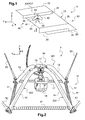
- the figure 1 has a protective device 20 according to the invention.
- This protection device 20 includes a protection plate 21 extending longitudinally from a free end before 22 to a rear free end 23, and transversely from a right side 24 to a left side 25.
- the protection device 20 has a knife 30 attached to the protection plate.
- the knife 30 extends in elevation from the guard plate to an edge 31, and transversely from the right side 24 to the left side 25.
- the knife 30 is further arranged under the guard plate longitudinally between the free end 22 and the rear free end 23.
- the figure 1 brings up a continuous knife.
- the knife 30 may have two discontinuous sections for severing each an arm of a fastening system.
- the protection device 20 comprises a compass 40.
- the compass 40 is fixed to the protection plate 20 by means support 26 extending transversely.
- the compass 40 is furthermore arranged under the protection plate longitudinally between the free end 22 and the free rear end 23.
- This compass 40 has two branches 41, 42 angularly separated by an angle ⁇ .
- the two branches can be attached to one another so as to constitute a single piece.
- Vertical forces shown schematically by the arrow F will then tend to unfold the compass by increasing the angle ⁇ .
- the two branches 41, 42 can be hinged to each other.
- a spacing means 45 then tends to unfold the compass by increasing the angle ⁇ .
- the compass can be articulated to the protection plate 21 about an AXROT axis of rotation.
- the fixing device 20 is then used within a fastening system 5 visible on the figure 2 to protect a fuselage.
- This fastening system 5 comprises a pyramidal structure 10 that can be suspended from a lower surface of a fuselage by means of suspension means 50.
- suspension means 50 Four suspension cables are thus represented on the figure 2 .
- the pyramidal structure 10 extends in elevation from a base to a vertex 16.
- the base consists of a frame 11 in the form of quadrilateral. This frame 11 is then provided with four tubes 11 'of delimitation.
- each arm 12, 13, 14, 15 can then be connected to the frame 11.
- each tube 11 'of the frame 11 extends between two lower ends of two arms.
- the upper ends of the arms 12, 13, 14, 15 then end on the top 16 of the pyramidal structure.
- the four arms include a first pair 301 of two arms 12, 13 directed for example towards the rear of a rotorcraft, and a second pair 302 of two arms 14, 15 directed towards the front of the rotorcraft. More precisely and by way of example, the first pair is provided with long arms, while the second pair is provided with short arms.
- the upper ends of the four arms can be attached to each other to form the top 16.
- frame means a quadrilateral shaped structure comprising at least one mechanical member.
- the upper ends of the two arms 14, 15 of the second pair 302 are secured to one another, and articulated to a base 17 about an axis of rotation 19.
- the upper ends of the two arms 12, 13 of the first pair 301 are secured to one another, and articulated to a base 17 about the axis of rotation 19.
- the pyramidal structure carries a hooking means 18, such as a hook-shed.
- hooking can be fixed to the base 17, or the base 17 can be part of the attachment means 18.
- the protective device is interposed between the top 16 of the pyramidal structure and the lower surface 4 of the fuselage 2 of a rotorcraft 1.
- the pyramidal structure is suspended from strong frames 3 of the rotorcraft 1 by the suspension means 50.
- the protection plate 21 is connected to the pyramidal structure to be able to move together with this pyramidal structure.
- the protection plate is for example fixed to the top 16.
- the protection plate is on the one hand suspended from the fuselage and, on the other hand, connected to the pyramidal structure.
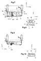
- the knife 30 is supported on the arms 12, 13 of the first pair 301, in their middle M1 for example.
- each leg of the compass is in contact at least transversely with an arm 14, 15 of the second pair 302, in its middle M2 for example.
- the compass can be articulated to the protection plate to be able to rotate about the axis of rotation AXROT jointly with the arms 14, 15 of the second pair 302.
- the protection plate is then resting against the fuselage.
- the protection plate may have acute angulation ⁇ with the lower surface 4.
- an elevation clearance 200 possibly remains between the protection plate and the top 16 of the structure.
- the angle ⁇ of the front compass 40 increases for a vertical force, given the pressure exerted on the arms 14, 15 of the second pair 302. This compass 40 thus forces these arms 14, 15 of the second pair 302 slightly to away.
- arms 14, 15 of the second pair 302 are embrittled laterally. These arms 14, 15 of the second pair 302 flex and tend to crash vertically.
- the spacing generated arms 14, 15 of the second pair 302 by the compass allows to release sufficient space to store the attachment means in a supine position.
- the protection plate also tends to protect the fuselage debris generated by the crushing of the pyramidal structure.
- a tank housed in the fuselage can then be caused to impact the protection plate at an acceptable speed.
Landscapes
- Engineering & Computer Science (AREA)
- Aviation & Aerospace Engineering (AREA)
- Mechanical Engineering (AREA)
- Emergency Lowering Means (AREA)
- Toys (AREA)
Applications Claiming Priority (1)
| Application Number | Priority Date | Filing Date | Title |
|---|---|---|---|
| FR1300521A FR3002920B1 (fr) | 2013-03-07 | 2013-03-07 | Dispositif pour proteger un giravion contre une structure pyramidale d'emport de charge |
Publications (2)
| Publication Number | Publication Date |
|---|---|
| EP2774841A1 true EP2774841A1 (de) | 2014-09-10 |
| EP2774841B1 EP2774841B1 (de) | 2015-12-23 |
Family
ID=48468454
Family Applications (1)
| Application Number | Title | Priority Date | Filing Date |
|---|---|---|---|
| EP14000462.3A Active EP2774841B1 (de) | 2013-03-07 | 2014-02-10 | Vorrichtung zum Schutz eines Drehflügelflugzeugs gegen eine pyramidale Struktur zur Lastbeförderung |
Country Status (3)
| Country | Link |
|---|---|
| US (1) | US9334042B2 (de) |
| EP (1) | EP2774841B1 (de) |
| FR (1) | FR3002920B1 (de) |
Families Citing this family (25)
| Publication number | Priority date | Publication date | Assignee | Title |
|---|---|---|---|---|
| FR3002919B1 (fr) * | 2013-03-07 | 2015-12-11 | Eurocopter France | Systeme de fixation d'une charge a un giravion, et un giravion |
| US9944394B2 (en) * | 2015-02-18 | 2018-04-17 | Boost Human External Cargo Systems Inc. | Belly-mounted load beam for an aerial vehicle |
| CA2929760C (en) * | 2015-05-12 | 2022-01-11 | Quanta Associates, L.P. | Hovering aircraft belly bar clasp |
| US10507920B2 (en) * | 2015-05-18 | 2019-12-17 | Sikorsky Aircraft Corp. | Systems and methods for lifting body vibration control |
| CH711888A8 (de) * | 2015-12-01 | 2017-08-15 | Marenco Swisshelicopter Ag | Helikopterlastenhaken. |
| US10745131B2 (en) | 2016-10-26 | 2020-08-18 | Boost Human External Cargo Systems Inc. | Belly-mounted load beam for an aerial vehicle |
| CN207292414U (zh) * | 2017-07-25 | 2018-05-01 | 深圳市大疆创新科技有限公司 | 防撞装置及具有该防撞装置的无人机 |
| US12434813B2 (en) | 2018-02-08 | 2025-10-07 | Vita Inclinata Ip Holdings Llc | Bidirectional thrust apparatus, system and method |
| US11142433B2 (en) | 2018-02-08 | 2021-10-12 | Vita Inclinata Technologies, Inc. | Bidirectional thrust apparatus, system, and method |
| US12246952B2 (en) | 2018-02-08 | 2025-03-11 | Vita Inclintata IP Holdings LLC | Hoist and deployable equipment apparatus, system, and method |
| US12304779B2 (en) | 2018-02-08 | 2025-05-20 | Vita Inclinata Ip Holdings Llc | On-board power and remote power for suspended load control apparatuses, systems, and methods |
| DE202019006130U1 (de) * | 2018-02-08 | 2025-04-14 | Vita Inclinata Ip Holdings Llc | Laststabilisationssystem |
| US11142316B2 (en) | 2018-02-08 | 2021-10-12 | Vita Inclinata Technologies, Inc. | Control of drone-load system method, system, and apparatus |
| US11209836B1 (en) | 2018-02-08 | 2021-12-28 | Vita Inclinata Technologies, Inc. | Long line loiter apparatus, system, and method |
| US11945697B2 (en) | 2018-02-08 | 2024-04-02 | Vita Inclinata Ip Holdings Llc | Multiple remote control for suspended load control equipment apparatus, system, and method |
| US10940061B2 (en) | 2018-02-08 | 2021-03-09 | Vita Inclinata Technologies, Inc. | Modular suspended load control apparatuses, systems, and methods |
| US11746951B2 (en) | 2019-02-26 | 2023-09-05 | Vita Inclinata Ip Holdings Llc | Cable deployment apparatus, system, and methods for suspended load control equipment |
| US11834305B1 (en) | 2019-04-12 | 2023-12-05 | Vita Inclinata Ip Holdings Llc | Apparatus, system, and method to control torque or lateral thrust applied to a load suspended on a suspension cable |
| WO2025122161A1 (en) | 2023-12-04 | 2025-06-12 | Vita Inclinata Ip Holdings Llc | Apparatus, system, and method to control torque or lateral thrust applied to a load suspended on a suspension cable |
| US11618566B1 (en) | 2019-04-12 | 2023-04-04 | Vita Inclinata Technologies, Inc. | State information and telemetry for suspended load control equipment apparatus, system, and method |
| CN114423703B (zh) | 2019-07-21 | 2025-06-24 | 维塔因克莱纳塔知识产权控股有限公司 | 提升机和可展开设备、装置、系统和方法 |
| EP4065468B1 (de) | 2019-11-25 | 2025-05-07 | Vita Inclinata IP Holdings LLC | Verfahren und vorrichtung zum steuern einer hängenden last |
| CH717076A2 (de) * | 2020-01-28 | 2021-07-30 | Marenco Ag | Lasthaken für Helikopter und Kräne. |
| ES2941797A1 (es) * | 2021-11-24 | 2023-05-25 | Aerocamaras S L | Sistema de rescate de animales con drones |
| JP7812585B2 (ja) | 2022-04-29 | 2026-02-10 | ビタ インクリナータ アイピー ホールディングス エルエルシー | 機械学習による不動産物の検出および解析装置、システム、及び方法 |
Citations (6)
| Publication number | Priority date | Publication date | Assignee | Title |
|---|---|---|---|---|
| US3044818A (en) * | 1961-05-02 | 1962-07-17 | Boeing Co | External cargo swing for aircraft |
| US4378919A (en) * | 1977-07-19 | 1983-04-05 | Erickson Air Crane Co. | Apparatus for controlling orientation of a suspended load |
| US5069318A (en) * | 1989-12-26 | 1991-12-03 | Mcdonnell Douglas Corporation | Self-stabilized stepped crashworthy stiffeners |
| US5344203A (en) * | 1992-03-09 | 1994-09-06 | Tollenaere Donald J | Aerodynamically-stabilized collapsible personnel and cargo basket for helicopters |
| WO1995006585A1 (fr) * | 1993-08-31 | 1995-03-09 | Centre National D'etudes Spatiales (C.N.E.S.) | Dispositif de protection destine a etre solidarise a une charge sous parachute en vue de proteger cette derniere lors de son atterrissage |
| EP2481671A2 (de) * | 2011-01-27 | 2012-08-01 | Eurocopter | Abnehmbare Befestigungsvorrichtung mit einem Befestigungsmittel für eine externe Last und einer Einrichtung zum Anbringen des Befestigungsmittels an einem Flugzeug, Flugzeug und zugehöriges Verfahren |
Family Cites Families (12)
| Publication number | Priority date | Publication date | Assignee | Title |
|---|---|---|---|---|
| US3446469A (en) * | 1967-11-14 | 1969-05-27 | Us Navy | Scissor shock platform |
| US3966144A (en) * | 1973-11-29 | 1976-06-29 | Edwin Zenith Gabriel | Duct system for wind gust alleviation of aircraft and suspended containerized loads |
| US3945674A (en) * | 1975-01-22 | 1976-03-23 | Metropolitan Stevedore Company | Load-retaining apparatus |
| US5190248A (en) * | 1989-11-08 | 1993-03-02 | Royal Ordnance Plc | Protection of aircraft structures |
| US6189834B1 (en) * | 1995-02-06 | 2001-02-20 | Skyhook Technologies, Inc. | Collapsible cargo management system for transporting payloads suspended from aircraft |
| FR2782060B1 (fr) * | 1998-08-06 | 2000-10-13 | Jean Francois Tardy | Dispositif suspendu a un engin porteur pour la recuperation d'individus ou de materiels |
| US6523450B1 (en) * | 2000-09-20 | 2003-02-25 | Arthur Schreiber | Exterior armor for use on bottom of helicopter |
| US7198224B2 (en) * | 2005-02-24 | 2007-04-03 | Sikorsky Aircraft Corporation | Energy absorbing airframe for a vertical lift vehicle |
| US7556471B1 (en) * | 2006-04-21 | 2009-07-07 | The United States Of America As Represented By The Secretary Of The Navy | Inter-ship personnel transfer device and method of moving between compacted state and non-compacted state |
| US9340284B2 (en) * | 2010-08-13 | 2016-05-17 | The United States Of America As Represented By The Secretary Of The Navy | Cargo suspension frame for aircraft |
| DE102010062018B4 (de) * | 2010-11-26 | 2015-05-13 | Airbus Operations Gmbh | Stützstab zur Stützung einer Fussbodenstruktur eines Flugzeugs |
| FR2992628B1 (fr) * | 2012-06-28 | 2015-03-20 | Airbus Operations Sas | Structure primaire de fuselage pour aeronef comprenant des entretoises a rupture anticipee pour accroitre l'absorption d'energie en cas de crash. |
-
2013
- 2013-03-07 FR FR1300521A patent/FR3002920B1/fr not_active Expired - Fee Related
-
2014
- 2014-02-10 EP EP14000462.3A patent/EP2774841B1/de active Active
- 2014-03-03 US US14/195,055 patent/US9334042B2/en not_active Expired - Fee Related
Patent Citations (6)
| Publication number | Priority date | Publication date | Assignee | Title |
|---|---|---|---|---|
| US3044818A (en) * | 1961-05-02 | 1962-07-17 | Boeing Co | External cargo swing for aircraft |
| US4378919A (en) * | 1977-07-19 | 1983-04-05 | Erickson Air Crane Co. | Apparatus for controlling orientation of a suspended load |
| US5069318A (en) * | 1989-12-26 | 1991-12-03 | Mcdonnell Douglas Corporation | Self-stabilized stepped crashworthy stiffeners |
| US5344203A (en) * | 1992-03-09 | 1994-09-06 | Tollenaere Donald J | Aerodynamically-stabilized collapsible personnel and cargo basket for helicopters |
| WO1995006585A1 (fr) * | 1993-08-31 | 1995-03-09 | Centre National D'etudes Spatiales (C.N.E.S.) | Dispositif de protection destine a etre solidarise a une charge sous parachute en vue de proteger cette derniere lors de son atterrissage |
| EP2481671A2 (de) * | 2011-01-27 | 2012-08-01 | Eurocopter | Abnehmbare Befestigungsvorrichtung mit einem Befestigungsmittel für eine externe Last und einer Einrichtung zum Anbringen des Befestigungsmittels an einem Flugzeug, Flugzeug und zugehöriges Verfahren |
Also Published As
| Publication number | Publication date |
|---|---|
| US9334042B2 (en) | 2016-05-10 |
| FR3002920B1 (fr) | 2015-03-27 |
| US20140252170A1 (en) | 2014-09-11 |
| EP2774841B1 (de) | 2015-12-23 |
| FR3002920A1 (fr) | 2014-09-12 |
Similar Documents
| Publication | Publication Date | Title |
|---|---|---|
| EP2774841B1 (de) | Vorrichtung zum Schutz eines Drehflügelflugzeugs gegen eine pyramidale Struktur zur Lastbeförderung | |
| EP2543594B1 (de) | Vorrichtung zur Befestigung und Kontrolle der Neigung einer Aussenlastbefestigung, und Luftfahrzeug | |
| EP3580087B1 (de) | Fahrzeugsitz mit kippbarer rückenlehne | |
| EP1928739A1 (de) | Verfahren zur montage eines fugzeugmotors auf einer starren strebenstruktur zur sicherung des motors | |
| EP2380809B1 (de) | Energieabsorptionssystem für ein Fahrwerk, und mit einem solchen Energieabsorptionssystem ausgestattetes Luftfahrzeug | |
| EP2774848A1 (de) | Befestigungssystem einer Ladung an einem Drehflügelflugzeug, und ein Drehflügelflugzeug | |
| EP2360093A1 (de) | Hubschrauber mit Notfahrwerk | |
| EP2735506B1 (de) | Verfahren zur Anbringung eines Schwimmersystems an einem Flugzeug, Schwimmersystem für ein Flugzeug, und ein Flugzeug | |
| EP2792594B1 (de) | Abnehmbares Trittbrett für Flugzeuge, und Flugzeug | |
| EP2332831B1 (de) | Hecksporn für ein Flugzeug, Flugzeug und Verfahren zum Verhindern des Kippens des Flugzeuges mittels des Hecksporns | |
| FR2890377A1 (fr) | Agencement adapte pour raccorder un palonnier a un mat d'accrochage de moteur d'aeronef | |
| FR2966476A1 (fr) | Dispositif de pose de cones de signalisation sur une voie de circulation | |
| FR2994686A1 (fr) | Procede de flottabilite d'un aeronef, systeme de flottabilite pour aeronef, et aeronef | |
| EP3932505A1 (de) | Passagierrückhaltesystem für achterbahnen | |
| FR2992289A1 (fr) | Train d'atterrissage d'un aeronef et aeronef | |
| CA2753849C (fr) | Aeronef, ensemble arriere dudit aeronef et moyen de protection dudit ensemble arriere d'un aeronef | |
| CA2805454C (fr) | Train d'atterrissage pour minimiser un risque d'accrochage d'un cable et aeronef | |
| EP1193137B1 (de) | Kraftfahrzeug mit herausziehbaren Kraftfahrzeug- Zellenschutzstangen | |
| FR3010667A1 (fr) | Siege pour vehicule militaire | |
| EP4438473B1 (de) | Drehflügelflugzeug, das mit einer durch ein kufenfahrwerk getragenen zelle mit zonen zur aufnahme variabler kräfte ausgestattet ist | |
| FR3048230A1 (fr) | Dispositif de rappel pour retracter un systeme mecanique mobile | |
| EP4279379A1 (de) | Kufenfahrwerk mit kufenverlängerungen zur verhinderung des einsinkens | |
| EP2727762A1 (de) | Formveränderbare Gondel für Fahrzeug | |
| FR3043963A1 (fr) | Vehicule automobile comprenant un organe de protection de la tete du pilote | |
| FR3021644A1 (fr) | Mat telescopique a dispositif de securite integre pour appareil de levage, et appareil de levage equipe d'un tel mat telescopique |
Legal Events
| Date | Code | Title | Description |
|---|---|---|---|
| PUAI | Public reference made under article 153(3) epc to a published international application that has entered the european phase |
Free format text: ORIGINAL CODE: 0009012 |
|
| 17P | Request for examination filed |
Effective date: 20140210 |
|
| AK | Designated contracting states |
Kind code of ref document: A1 Designated state(s): AL AT BE BG CH CY CZ DE DK EE ES FI FR GB GR HR HU IE IS IT LI LT LU LV MC MK MT NL NO PL PT RO RS SE SI SK SM TR |
|
| AX | Request for extension of the european patent |
Extension state: BA ME |
|
| R17P | Request for examination filed (corrected) |
Effective date: 20141205 |
|
| RBV | Designated contracting states (corrected) |
Designated state(s): AL AT BE BG CH CY CZ DE DK EE ES FI FR GB GR HR HU IE IS IT LI LT LU LV MC MK MT NL NO PL PT RO RS SE SI SK SM TR |
|
| GRAP | Despatch of communication of intention to grant a patent |
Free format text: ORIGINAL CODE: EPIDOSNIGR1 |
|
| INTG | Intention to grant announced |
Effective date: 20150616 |
|
| GRAP | Despatch of communication of intention to grant a patent |
Free format text: ORIGINAL CODE: EPIDOSNIGR1 |
|
| INTG | Intention to grant announced |
Effective date: 20151002 |
|
| GRAS | Grant fee paid |
Free format text: ORIGINAL CODE: EPIDOSNIGR3 |
|
| GRAA | (expected) grant |
Free format text: ORIGINAL CODE: 0009210 |
|
| AK | Designated contracting states |
Kind code of ref document: B1 Designated state(s): AL AT BE BG CH CY CZ DE DK EE ES FI FR GB GR HR HU IE IS IT LI LT LU LV MC MK MT NL NO PL PT RO RS SE SI SK SM TR |
|
| REG | Reference to a national code |
Ref country code: GB Ref legal event code: FG4D Free format text: NOT ENGLISH |
|
| REG | Reference to a national code |
Ref country code: CH Ref legal event code: EP |
|
| REG | Reference to a national code |
Ref country code: IE Ref legal event code: FG4D Free format text: LANGUAGE OF EP DOCUMENT: FRENCH |
|
| REG | Reference to a national code |
Ref country code: AT Ref legal event code: REF Ref document number: 766430 Country of ref document: AT Kind code of ref document: T Effective date: 20160115 |
|
| REG | Reference to a national code |
Ref country code: DE Ref legal event code: R096 Ref document number: 602014000568 Country of ref document: DE |
|
| REG | Reference to a national code |
Ref country code: FR Ref legal event code: PLFP Year of fee payment: 3 |
|
| REG | Reference to a national code |
Ref country code: LT Ref legal event code: MG4D |
|
| REG | Reference to a national code |
Ref country code: NL Ref legal event code: MP Effective date: 20151223 |
|
| PG25 | Lapsed in a contracting state [announced via postgrant information from national office to epo] |
Ref country code: LT Free format text: LAPSE BECAUSE OF FAILURE TO SUBMIT A TRANSLATION OF THE DESCRIPTION OR TO PAY THE FEE WITHIN THE PRESCRIBED TIME-LIMIT Effective date: 20151223 Ref country code: HR Free format text: LAPSE BECAUSE OF FAILURE TO SUBMIT A TRANSLATION OF THE DESCRIPTION OR TO PAY THE FEE WITHIN THE PRESCRIBED TIME-LIMIT Effective date: 20151223 Ref country code: NO Free format text: LAPSE BECAUSE OF FAILURE TO SUBMIT A TRANSLATION OF THE DESCRIPTION OR TO PAY THE FEE WITHIN THE PRESCRIBED TIME-LIMIT Effective date: 20160323 |
|
| REG | Reference to a national code |
Ref country code: AT Ref legal event code: MK05 Ref document number: 766430 Country of ref document: AT Kind code of ref document: T Effective date: 20151223 |
|
| PG25 | Lapsed in a contracting state [announced via postgrant information from national office to epo] |
Ref country code: BE Free format text: LAPSE BECAUSE OF NON-PAYMENT OF DUE FEES Effective date: 20160229 Ref country code: SE Free format text: LAPSE BECAUSE OF FAILURE TO SUBMIT A TRANSLATION OF THE DESCRIPTION OR TO PAY THE FEE WITHIN THE PRESCRIBED TIME-LIMIT Effective date: 20151223 Ref country code: GR Free format text: LAPSE BECAUSE OF FAILURE TO SUBMIT A TRANSLATION OF THE DESCRIPTION OR TO PAY THE FEE WITHIN THE PRESCRIBED TIME-LIMIT Effective date: 20160324 Ref country code: LV Free format text: LAPSE BECAUSE OF FAILURE TO SUBMIT A TRANSLATION OF THE DESCRIPTION OR TO PAY THE FEE WITHIN THE PRESCRIBED TIME-LIMIT Effective date: 20151223 Ref country code: FI Free format text: LAPSE BECAUSE OF FAILURE TO SUBMIT A TRANSLATION OF THE DESCRIPTION OR TO PAY THE FEE WITHIN THE PRESCRIBED TIME-LIMIT Effective date: 20151223 Ref country code: NL Free format text: LAPSE BECAUSE OF FAILURE TO SUBMIT A TRANSLATION OF THE DESCRIPTION OR TO PAY THE FEE WITHIN THE PRESCRIBED TIME-LIMIT Effective date: 20151223 Ref country code: RS Free format text: LAPSE BECAUSE OF FAILURE TO SUBMIT A TRANSLATION OF THE DESCRIPTION OR TO PAY THE FEE WITHIN THE PRESCRIBED TIME-LIMIT Effective date: 20151223 |
|
| PG25 | Lapsed in a contracting state [announced via postgrant information from national office to epo] |
Ref country code: CZ Free format text: LAPSE BECAUSE OF FAILURE TO SUBMIT A TRANSLATION OF THE DESCRIPTION OR TO PAY THE FEE WITHIN THE PRESCRIBED TIME-LIMIT Effective date: 20151223 Ref country code: ES Free format text: LAPSE BECAUSE OF FAILURE TO SUBMIT A TRANSLATION OF THE DESCRIPTION OR TO PAY THE FEE WITHIN THE PRESCRIBED TIME-LIMIT Effective date: 20151223 |
|
| PG25 | Lapsed in a contracting state [announced via postgrant information from national office to epo] |
Ref country code: RO Free format text: LAPSE BECAUSE OF FAILURE TO SUBMIT A TRANSLATION OF THE DESCRIPTION OR TO PAY THE FEE WITHIN THE PRESCRIBED TIME-LIMIT Effective date: 20151223 Ref country code: AT Free format text: LAPSE BECAUSE OF FAILURE TO SUBMIT A TRANSLATION OF THE DESCRIPTION OR TO PAY THE FEE WITHIN THE PRESCRIBED TIME-LIMIT Effective date: 20151223 Ref country code: IS Free format text: LAPSE BECAUSE OF FAILURE TO SUBMIT A TRANSLATION OF THE DESCRIPTION OR TO PAY THE FEE WITHIN THE PRESCRIBED TIME-LIMIT Effective date: 20160423 Ref country code: EE Free format text: LAPSE BECAUSE OF FAILURE TO SUBMIT A TRANSLATION OF THE DESCRIPTION OR TO PAY THE FEE WITHIN THE PRESCRIBED TIME-LIMIT Effective date: 20151223 Ref country code: PT Free format text: LAPSE BECAUSE OF FAILURE TO SUBMIT A TRANSLATION OF THE DESCRIPTION OR TO PAY THE FEE WITHIN THE PRESCRIBED TIME-LIMIT Effective date: 20160426 Ref country code: SK Free format text: LAPSE BECAUSE OF FAILURE TO SUBMIT A TRANSLATION OF THE DESCRIPTION OR TO PAY THE FEE WITHIN THE PRESCRIBED TIME-LIMIT Effective date: 20151223 Ref country code: PL Free format text: LAPSE BECAUSE OF FAILURE TO SUBMIT A TRANSLATION OF THE DESCRIPTION OR TO PAY THE FEE WITHIN THE PRESCRIBED TIME-LIMIT Effective date: 20151223 Ref country code: SM Free format text: LAPSE BECAUSE OF FAILURE TO SUBMIT A TRANSLATION OF THE DESCRIPTION OR TO PAY THE FEE WITHIN THE PRESCRIBED TIME-LIMIT Effective date: 20151223 |
|
| REG | Reference to a national code |
Ref country code: DE Ref legal event code: R119 Ref document number: 602014000568 Country of ref document: DE |
|
| PG25 | Lapsed in a contracting state [announced via postgrant information from national office to epo] |
Ref country code: LU Free format text: LAPSE BECAUSE OF FAILURE TO SUBMIT A TRANSLATION OF THE DESCRIPTION OR TO PAY THE FEE WITHIN THE PRESCRIBED TIME-LIMIT Effective date: 20160210 Ref country code: MC Free format text: LAPSE BECAUSE OF FAILURE TO SUBMIT A TRANSLATION OF THE DESCRIPTION OR TO PAY THE FEE WITHIN THE PRESCRIBED TIME-LIMIT Effective date: 20151223 |
|
| PLBE | No opposition filed within time limit |
Free format text: ORIGINAL CODE: 0009261 |
|
| STAA | Information on the status of an ep patent application or granted ep patent |
Free format text: STATUS: NO OPPOSITION FILED WITHIN TIME LIMIT |
|
| PG25 | Lapsed in a contracting state [announced via postgrant information from national office to epo] |
Ref country code: DK Free format text: LAPSE BECAUSE OF FAILURE TO SUBMIT A TRANSLATION OF THE DESCRIPTION OR TO PAY THE FEE WITHIN THE PRESCRIBED TIME-LIMIT Effective date: 20151223 |
|
| 26N | No opposition filed |
Effective date: 20160926 |
|
| REG | Reference to a national code |
Ref country code: IE Ref legal event code: MM4A |
|
| PG25 | Lapsed in a contracting state [announced via postgrant information from national office to epo] |
Ref country code: IE Free format text: LAPSE BECAUSE OF NON-PAYMENT OF DUE FEES Effective date: 20160210 Ref country code: DE Free format text: LAPSE BECAUSE OF NON-PAYMENT OF DUE FEES Effective date: 20160901 |
|
| REG | Reference to a national code |
Ref country code: FR Ref legal event code: PLFP Year of fee payment: 4 |
|
| PG25 | Lapsed in a contracting state [announced via postgrant information from national office to epo] |
Ref country code: SI Free format text: LAPSE BECAUSE OF FAILURE TO SUBMIT A TRANSLATION OF THE DESCRIPTION OR TO PAY THE FEE WITHIN THE PRESCRIBED TIME-LIMIT Effective date: 20151223 |
|
| PG25 | Lapsed in a contracting state [announced via postgrant information from national office to epo] |
Ref country code: MT Free format text: LAPSE BECAUSE OF FAILURE TO SUBMIT A TRANSLATION OF THE DESCRIPTION OR TO PAY THE FEE WITHIN THE PRESCRIBED TIME-LIMIT Effective date: 20151223 |
|
| REG | Reference to a national code |
Ref country code: CH Ref legal event code: PL |
|
| PG25 | Lapsed in a contracting state [announced via postgrant information from national office to epo] |
Ref country code: CH Free format text: LAPSE BECAUSE OF NON-PAYMENT OF DUE FEES Effective date: 20170228 Ref country code: LI Free format text: LAPSE BECAUSE OF NON-PAYMENT OF DUE FEES Effective date: 20170228 |
|
| REG | Reference to a national code |
Ref country code: FR Ref legal event code: PLFP Year of fee payment: 5 |
|
| PG25 | Lapsed in a contracting state [announced via postgrant information from national office to epo] |
Ref country code: HU Free format text: LAPSE BECAUSE OF FAILURE TO SUBMIT A TRANSLATION OF THE DESCRIPTION OR TO PAY THE FEE WITHIN THE PRESCRIBED TIME-LIMIT; INVALID AB INITIO Effective date: 20140210 |
|
| PG25 | Lapsed in a contracting state [announced via postgrant information from national office to epo] |
Ref country code: TR Free format text: LAPSE BECAUSE OF FAILURE TO SUBMIT A TRANSLATION OF THE DESCRIPTION OR TO PAY THE FEE WITHIN THE PRESCRIBED TIME-LIMIT Effective date: 20151223 Ref country code: MK Free format text: LAPSE BECAUSE OF FAILURE TO SUBMIT A TRANSLATION OF THE DESCRIPTION OR TO PAY THE FEE WITHIN THE PRESCRIBED TIME-LIMIT Effective date: 20151223 Ref country code: CY Free format text: LAPSE BECAUSE OF FAILURE TO SUBMIT A TRANSLATION OF THE DESCRIPTION OR TO PAY THE FEE WITHIN THE PRESCRIBED TIME-LIMIT Effective date: 20151223 |
|
| PG25 | Lapsed in a contracting state [announced via postgrant information from national office to epo] |
Ref country code: BG Free format text: LAPSE BECAUSE OF FAILURE TO SUBMIT A TRANSLATION OF THE DESCRIPTION OR TO PAY THE FEE WITHIN THE PRESCRIBED TIME-LIMIT Effective date: 20151223 |
|
| PG25 | Lapsed in a contracting state [announced via postgrant information from national office to epo] |
Ref country code: AL Free format text: LAPSE BECAUSE OF FAILURE TO SUBMIT A TRANSLATION OF THE DESCRIPTION OR TO PAY THE FEE WITHIN THE PRESCRIBED TIME-LIMIT Effective date: 20151223 |
|
| P01 | Opt-out of the competence of the unified patent court (upc) registered |
Effective date: 20230530 |
|
| PGFP | Annual fee paid to national office [announced via postgrant information from national office to epo] |
Ref country code: GB Payment date: 20260219 Year of fee payment: 13 |
|
| PGFP | Annual fee paid to national office [announced via postgrant information from national office to epo] |
Ref country code: IT Payment date: 20260224 Year of fee payment: 13 |
|
| PGFP | Annual fee paid to national office [announced via postgrant information from national office to epo] |
Ref country code: FR Payment date: 20260218 Year of fee payment: 13 |