EP2774789A1 - Heizvorrichtung für eine mobile Arbeitsmaschine - Google Patents
Heizvorrichtung für eine mobile Arbeitsmaschine Download PDFInfo
- Publication number
- EP2774789A1 EP2774789A1 EP14156791.7A EP14156791A EP2774789A1 EP 2774789 A1 EP2774789 A1 EP 2774789A1 EP 14156791 A EP14156791 A EP 14156791A EP 2774789 A1 EP2774789 A1 EP 2774789A1
- Authority
- EP
- European Patent Office
- Prior art keywords
- heat exchanger
- hydraulic circuit
- heat
- heating
- heating device
- Prior art date
- Legal status (The legal status is an assumption and is not a legal conclusion. Google has not performed a legal analysis and makes no representation as to the accuracy of the status listed.)
- Granted
Links
Images


Classifications
-
- B—PERFORMING OPERATIONS; TRANSPORTING
- B60—VEHICLES IN GENERAL
- B60H—ARRANGEMENTS OF HEATING, COOLING, VENTILATING OR OTHER AIR-TREATING DEVICES SPECIALLY ADAPTED FOR PASSENGER OR GOODS SPACES OF VEHICLES
- B60H1/00—Heating, cooling or ventilating devices
- B60H1/00357—Air-conditioning arrangements specially adapted for particular vehicles
- B60H1/00378—Air-conditioning arrangements specially adapted for particular vehicles for tractor or load vehicle cabins
-
- B—PERFORMING OPERATIONS; TRANSPORTING
- B60—VEHICLES IN GENERAL
- B60H—ARRANGEMENTS OF HEATING, COOLING, VENTILATING OR OTHER AIR-TREATING DEVICES SPECIALLY ADAPTED FOR PASSENGER OR GOODS SPACES OF VEHICLES
- B60H1/00—Heating, cooling or ventilating devices
- B60H1/00642—Control systems or circuits; Control members or indication devices for heating, cooling or ventilating devices
- B60H1/00814—Control systems or circuits characterised by their output, for controlling particular components of the heating, cooling or ventilating installation
- B60H1/00878—Control systems or circuits characterised by their output, for controlling particular components of the heating, cooling or ventilating installation the components being temperature regulating devices
- B60H1/00899—Controlling the flow of liquid in a heat pump system
-
- B—PERFORMING OPERATIONS; TRANSPORTING
- B60—VEHICLES IN GENERAL
- B60H—ARRANGEMENTS OF HEATING, COOLING, VENTILATING OR OTHER AIR-TREATING DEVICES SPECIALLY ADAPTED FOR PASSENGER OR GOODS SPACES OF VEHICLES
- B60H1/00—Heating, cooling or ventilating devices
- B60H1/02—Heating, cooling or ventilating devices the heat being derived from the propulsion plant
- B60H1/14—Heating, cooling or ventilating devices the heat being derived from the propulsion plant other than from cooling liquid of the plant
-
- B—PERFORMING OPERATIONS; TRANSPORTING
- B60—VEHICLES IN GENERAL
- B60H—ARRANGEMENTS OF HEATING, COOLING, VENTILATING OR OTHER AIR-TREATING DEVICES SPECIALLY ADAPTED FOR PASSENGER OR GOODS SPACES OF VEHICLES
- B60H1/00—Heating, cooling or ventilating devices
- B60H1/00642—Control systems or circuits; Control members or indication devices for heating, cooling or ventilating devices
- B60H1/00814—Control systems or circuits characterised by their output, for controlling particular components of the heating, cooling or ventilating installation
- B60H1/00878—Control systems or circuits characterised by their output, for controlling particular components of the heating, cooling or ventilating installation the components being temperature regulating devices
- B60H2001/00949—Control systems or circuits characterised by their output, for controlling particular components of the heating, cooling or ventilating installation the components being temperature regulating devices comprising additional heating/cooling sources, e.g. second evaporator
-
- F—MECHANICAL ENGINEERING; LIGHTING; HEATING; WEAPONS; BLASTING
- F25—REFRIGERATION OR COOLING; COMBINED HEATING AND REFRIGERATION SYSTEMS; HEAT PUMP SYSTEMS; MANUFACTURE OR STORAGE OF ICE; LIQUEFACTION SOLIDIFICATION OF GASES
- F25B—REFRIGERATION MACHINES, PLANTS OR SYSTEMS; COMBINED HEATING AND REFRIGERATION SYSTEMS; HEAT PUMP SYSTEMS
- F25B2339/00—Details of evaporators; Details of condensers
- F25B2339/04—Details of condensers
- F25B2339/047—Water-cooled condensers
-
- F—MECHANICAL ENGINEERING; LIGHTING; HEATING; WEAPONS; BLASTING
- F25—REFRIGERATION OR COOLING; COMBINED HEATING AND REFRIGERATION SYSTEMS; HEAT PUMP SYSTEMS; MANUFACTURE OR STORAGE OF ICE; LIQUEFACTION SOLIDIFICATION OF GASES
- F25B—REFRIGERATION MACHINES, PLANTS OR SYSTEMS; COMBINED HEATING AND REFRIGERATION SYSTEMS; HEAT PUMP SYSTEMS
- F25B25/00—Machines, plants or systems, using a combination of modes of operation covered by two or more of the groups F25B1/00 - F25B23/00
- F25B25/005—Machines, plants or systems, using a combination of modes of operation covered by two or more of the groups F25B1/00 - F25B23/00 using primary and secondary systems
-
- F—MECHANICAL ENGINEERING; LIGHTING; HEATING; WEAPONS; BLASTING
- F25—REFRIGERATION OR COOLING; COMBINED HEATING AND REFRIGERATION SYSTEMS; HEAT PUMP SYSTEMS; MANUFACTURE OR STORAGE OF ICE; LIQUEFACTION SOLIDIFICATION OF GASES
- F25B—REFRIGERATION MACHINES, PLANTS OR SYSTEMS; COMBINED HEATING AND REFRIGERATION SYSTEMS; HEAT PUMP SYSTEMS
- F25B30/00—Heat pumps
- F25B30/02—Heat pumps of the compression type
-
- Y—GENERAL TAGGING OF NEW TECHNOLOGICAL DEVELOPMENTS; GENERAL TAGGING OF CROSS-SECTIONAL TECHNOLOGIES SPANNING OVER SEVERAL SECTIONS OF THE IPC; TECHNICAL SUBJECTS COVERED BY FORMER USPC CROSS-REFERENCE ART COLLECTIONS [XRACs] AND DIGESTS
- Y02—TECHNOLOGIES OR APPLICATIONS FOR MITIGATION OR ADAPTATION AGAINST CLIMATE CHANGE
- Y02A—TECHNOLOGIES FOR ADAPTATION TO CLIMATE CHANGE
- Y02A40/00—Adaptation technologies in agriculture, forestry, livestock or agroalimentary production
- Y02A40/90—Adaptation technologies in agriculture, forestry, livestock or agroalimentary production in food processing or handling, e.g. food conservation
- Y02A40/963—Off-grid food refrigeration
Definitions
- the invention relates to a heating device for a mobile work machine.
- the invention relates to a heater for a mobile work machine, such as an industrial truck, with a heating heat exchanger, wherein the mobile machine has a hydraulic circuit.
- an air-blower heater is often used as a heating system in which heated air is blown into the cab room and the heating of the air takes place by an electric heating element as a heating heat exchanger.
- a heat pump which uses the ambient air via an air heat exchanger as a heat source.
- a well-known example of this is to use an air conditioner whose condenser serves as a heating heat exchanger for the cabin interior air. As far as the operation of the heat pump can be reversed, this can also be provided at the same time a cooling facility for the driver's cab.
- a disadvantage of this prior art is that the efficiency of a heat pump depends strongly on the temperature of the heat source. Especially at low outdoor temperatures in an outdoor area and consequently a strong heating demand for a cab, however, is available in the form of ambient air, only a heat source with very low temperature. This, in turn, degrades efficiency and results in increased power consumption as well as faster draining of the traction battery in a battery-powered vehicle.
- hybrid vehicles for road transport which are driven by a combination of internal combustion engine and electric motor and at least for the internal combustion engine, but possibly also for other components have a cooling water circuit.
- a combined heating / cooling unit which can work as a heat pump in two directions and, in particular, for the heating of the passenger compartment heat can take the cooling water circuit as a heat source.
- a disadvantage of this prior art is that it can not be used in battery-powered mobile work machines and especially not for industrial trucks, as these usually no cooling water circuit is present.
- Mobile machines and especially trucks, such as forklifts with a lifting device usually have working devices and components that are hydraulically driven and in which a driven in the case of a battery electric vehicle by an electric motor hydraulic pump promotes pressure fluid from a tank that performs at a consumer work performance and then back into the tank.
- the present invention has for its object to provide a mobile work machine, in particular a truck, which is powered by battery and has a heated cab or temperature-dependent heated components, wherein the above-mentioned disadvantages are avoided and the energy consumption is optimized.
- the object is achieved in that in a heater for a mobile machine, especially a truck, with a heating heat exchanger, the mobile machine has a hydraulic circuit is used as a heat source for the heating heat exchanger of the hydraulic circuit.
- the pressure medium of the hydraulic circuit is heated during operation of a mobile work machine such as an industrial truck or other vehicles up to a medium temperature range.
- temperature levels can be up to about 65 ° C.
- a higher temperature than the starting temperature available or it is also conceivable, possibly directly with the pressure medium of the hydraulic circuit to heat the heating heat exchanger.
- the heater can cover any heating demand, including heating high performance batteries after a vehicle is powered up to a minimum operating temperature, such as lithium-ion batteries. It is also conceivable to heat by the heater and a power electronics after the commissioning of the mobile machine until it reaches an optimal operating temperature.
- the heating heat exchanger is used to heat the air of a driver's cab.
- the proposed solution therefore has a particularly advantageous effect on the energy consumption and thus the operating time with a battery charge.
- the heating heat exchanger is heated by a heat pump, which uses the hydraulic circuit as a heat source via a hydraulic circuit heat exchanger.
- an ambient air heat exchanger is provided as a further heat source for the heat pump.
- the pressure medium must not be over-cooled to avoid disadvantages in wear and efficiency of the hydraulic system. Therefore, it is advantageous to additionally provide an alternative heat source or to use these in combination, for example, also graduated in series successively according to the temperature levels.
- these can be used and for further heating to the ambient air of the hydraulic circuit.
- an evaporator of an air conditioner can be heated as a heat pump. If the temperature level in the hydraulic system and / or the delivered amount of heat of the hydraulic system is not sufficient, so only the ambient air can be used as a heat source, albeit with reduced efficiency.
- the hydraulic circuit heat exchanger and the ambient air heat exchanger via a water cycle with the heat pump, in particular with a heat exchanger of Heat pump to be connected, the division of the water flow between the hydraulic circuit heat exchanger and the ambient air heat exchanger is controlled by a valve device.
- the hydraulic circuit heat exchanger is arranged in a pressure medium tank of the hydraulic circuit.
- the hydraulic circuit heat exchanger can be an internal heat exchanger of the heat pump and the ambient air heat exchanger can be connected via a water circuit to the heat pump, in particular to a heat exchanger of the heat pump.
- the heat of the hydraulic circuit via the hydraulic circuit heat exchanger is fed directly to the heat pump, while heat from the ambient air heat exchanger via a water intermediate circuit and another heat exchanger in the heat pump is supplied to this.
- the hydraulic circuit heat exchanger is an internal heat exchanger of the heat pump and the ambient air heat exchanger is connected via the hydraulic circuit to the hydraulic circuit heat exchanger.
- the distribution of the pressure medium passage through the hydraulic circuit heat exchanger from the ambient air heat exchanger in relation to the rest of the hydraulic circuit by a valve device is adjustable.
- an already existing cooler for the pressure medium of the hydraulic circuit can be advantageously and inexpensively used, which emits waste heat of the hydraulic circuit to the ambient air.
- the valve device can be controlled in a simple manner and, for example, temperature-dependent, in what proportion heat can be removed from the hydraulic circuit to serve as a heat source of the heat pump and to what extent heat is supplied from the ambient air heat exchanger.
- the working direction of the heat pump can be reversible and the heating heat exchanger can be cooled.
- the ambient air heat exchanger is used as a heat sink, but it is also conceivable to deliver waste heat to the hydraulic system, if the temperature of the pressure medium is not too high.
- the temperature of the pressure medium in the hydraulic circuit can be raised by a neutral circulation and / or circulation of the pressure medium against a throttle.
- the Fig. 1 shows a mobile machine 1 with a heater according to the invention, which is designed as a truck, here as a counterbalance forklift 2, with a driver's cab 3, in which a driver's workplace 4 is located with a driver's seat 5.
- the counterbalance forklift 2 has a battery-electrically driven vehicle, which is driven by electric motors, not shown, for supplying energy to an electrical energy storage device 6, which is formed for example as a lithium-ion battery 7.
- an electrical energy storage device 6 which is formed for example as a lithium-ion battery 7.
- a load fork 9 is arranged for receiving a load, wherein the weight of this load is compensated by a counterweight 10.
- the driver's workplace 4 has a steering wheel 11.
- An ambient air heat exchanger 12 is arranged on the roof rear side of the driver's cab 3 and absorbs heat from the ambient air, which flows through it as indicated by arrows.
- a heating heat exchanger 13 is arranged in a console 14 of the driver's cab 3 and, as shown by the arrows, flows through the air in the interior of the driver's cab 3.
- the fork 9 can be raised on the mast 8 by a hydraulic lifting cylinder, not shown, which is part of a working hydraulics with a hydraulic circuit of the counterbalance forklift 2.
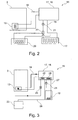
- the Fig. 2 shows a schematic of a first embodiment of a heating device 15 according to the invention.
- the driver's cab 3 has the heating heat exchanger 13, which is heated via a water circuit 16 by a heat pump 17, which is designed as an air conditioner 18.
- the heat pump 17 is connected to the ambient air heat exchanger 12 and a hydraulic circuit heat exchanger 20, which may be arranged in a pressure medium tank of the hydraulic circuit.
- the water in the further water circuit 19 is circulated by a circulation pump 21 and a valve means 22, the proportion of water flowing through the hydraulic circuit heat exchanger 20, compared to the proportion of water flowing through the ambient air heat exchanger 12, are regulated up to a sole flow through one of the two heat exchangers 12,20.
- the air conditioning system 18 can be supplied with heat energy as heat pump 17 alone from the hydraulic circuit heat exchanger 20. However, if the available heat energy in the hydraulic circuit heat exchanger 20 is insufficient, the heat pump 17 may be supplied with heat from the ambient air heat exchanger 12. Conversely, if the heat pump 17 also allows reverse operation, the interior of the cab 3 to be cooled by the heating heat exchanger 13 and the waste heat through the ambient air heat exchanger 12 are discharged to the ambient air.
- the Fig. 3 shows a diagram of a second embodiment of a heating device 15 according to the invention are doing to the components of the embodiment of Fig. 1 identical components provided with the same reference numerals.
- the driver's cab 3 with the heating heat exchanger 13 is heated via the water circuit 16 by a heat pump 17 or the air-conditioning system 18.
- a hydraulic circuit 23 is connected via a pressure medium line 24, in which a reservoir 25 is inserted, with a hydraulic circuit heat exchanger 26 which is integrated into the heat pump 17.
- the supply of the heat energy from the hydraulic circuit 23 is completely separated from the supply of heat energy from the ambient air heat exchanger 12.
- the Fig. 4 shows a schematic of a third embodiment of a heating device 15 according to the invention.
- the driver's cab 3 with the heating heat exchanger 13 is heated by the water cycle 16 from a heat pump 17 or the air conditioning system 18.
- the hydraulic circuit 23 is connected via the pressure medium line 24 with the hydraulic circuit heat exchanger 26, which is integrated into the heat pump 17.
- the ambient air heat exchanger 12 is integrated into the pressure medium line 24 as part of the hydraulic circuit 23.
- the ambient air heat exchanger 12 energy from the ambient air of the heat pump 17 supply when the temperature of the pressure medium below a minimum allowed temperature, so that in this case only energy from the ambient air of the heat pump 17 is supplied.
- This solution is particularly cost-effective and easy to implement when the hydraulic circuit 23 already has an ambient air heat exchanger 12 for the cooling of the pressure medium.
Landscapes
- Engineering & Computer Science (AREA)
- Physics & Mathematics (AREA)
- Thermal Sciences (AREA)
- Mechanical Engineering (AREA)
- Chemical & Material Sciences (AREA)
- Combustion & Propulsion (AREA)
- Air-Conditioning For Vehicles (AREA)
- Forklifts And Lifting Vehicles (AREA)
Abstract
Description
- Die Erfindung betrifft eine Heizvorrichtung für eine mobile Arbeitsmaschine. Insbesondere betrifft die Erfindung eine Heizvorrichtung für eine mobile Arbeitsmaschine, etwa beispielsweise ein Flurförderzeug, mit einem Heizwärmetauscher, wobei die mobile Arbeitsmaschine einen Hydraulikkreislauf aufweist.
- Viele mobile Arbeitsmaschinen und insbesondere Flurförderzeuge weisen eine Fahrerkabine auf, um den Fahrer der mobilen Arbeitsmaschine vor Witterungseinflüssen, vor allem Regen, zu schützen. Bei mobilen Arbeitsmaschinen besteht dabei im Regelfall die Möglichkeit, die Fahrerkabine zu beheizen, um die Arbeitsbedingungen des Fahrers zu verbessern, wenn die mobile Arbeitsmaschine in einem Freigelände ganzjährig eingesetzt wird. Ein Beispiel solcher mobiler Arbeitsmaschinen sind Flurförderzeuge und insbesondere Gabelstapler bzw. Gegengewichtsgabelstapler, die auf Betriebsgeländen sowohl innerhalb von Lagerhallen, wie auch auf Freigeländen eingesetzt werden.
- Viele mobile Arbeitsmaschinen und insbesondere Flurförderzeuge sind dabei batterieelektrische Fahrzeuge, die keinen Verbrennungsmotor aufweisen und somit auch im Regelfall keinen Flüssigkeitskühlkreis eines Verbrennungsmotors. Bei diesen wird oftmals als Heizsystem eine Luft-Gebläse Heizung eingesetzt, bei der erwärmte Luft in den Fahrerkabinenraum geblasen wird und die Erwärmung der Luft durch ein elektrisches Heizelement als Heizwärmetauscher erfolgt.
- Nachteilig an diesem Stand der Technik ist jedoch, dass die Nutzung der elektrischen, in einer Traktionsbatterie gespeicherten Energie für Heizzwecke zu einer erheblichen Reduzierung der Reichweite und Arbeitsdauer mit einer Batterieladung führt.
- Zur Vermeidung dieser starken Reduzierung der Reichweite und des hohen Energieverbrauchs bei direkter Beheizung durch elektrischen Strom ist es bekannt, für die Erwärmung der Luft eine Wärmepumpe einzusetzen, die als Wärmequelle die Umgebungsluft über einen Luftwärmetauscher nutzt. Ein bekanntes Beispiel hierfür ist, eine Klimaanlage einzusetzen, deren Kondensator als Heizwärmetauscher für die Kabineninnenluft dient. Soweit die Wirkungsweise der Wärmepumpe auch umgekehrt werden kann, kann dadurch gleichzeitig auch eine Kühlmöglichkeit für die Fahrerkabine vorgesehen werden.
- Nachteilig an diesem Stand der Technik ist, dass der Wirkungsgrad einer Wärmepumpe stark von der Temperatur der Wärmequelle abhängt. Gerade bei niedrigen Außentemperaturen in einem Freigelände und folglich starkem Heizbedarf für eine Fahrerkabine steht jedoch in Form der Umgebungsluft nur eine Wärmequelle mit sehr niedriger Temperatur zur Verfügung. Dies verschlechtert wiederum den Wirkungsgrad und führt zu einem erhöhten Energieverbrauch sowie einer schnelleren Entleerung der Traktionsbatterie bei einem Batterie-elektrisch angetriebenen Fahrzeug.
- Bekannt sind Hybridfahrzeuge für den Straßenverkehr, die durch eine Kombination aus Verbrennungsmotor und Elektromotor angetrieben werden und zumindest für den Verbrennungsmotor, aber auch eventuell für weitere Komponenten einen Kühlwasserkreislauf aufweisen. Für die Klimatisierung des Fahrgastraumes ist bei diesen Fahrzeugen es denkbar, eine kombinierte Heiz-/Kühleinheit einzusetzen die als Wärmepumpe in zwei Richtungen arbeiten kann und insbesondere für die Beheizung des Fahrgastraumes Wärme dem Kühlwasserkreislauf als Wärmequelle entnehmen kann.
- Nachteilig an diesem Stand der Technik ist, dass er nicht bei batterieelektrisch angetriebenen mobilen Arbeitsmaschinen und insbesondere nicht bei Flurförderzeugen eingesetzt werden kann, da bei diesen im Regelfall kein Kühlwasserkreislauf vorhanden ist.
- Mobile Arbeitsmaschinen und insbesondere Flurförderzeuge, beispielsweise Gabelstapler mit einer Hubvorrichtung, weisen im Regelfall Arbeitsvorrichtungen und Komponenten auf, die hydraulisch angetrieben werden und bei denen eine im Falle eines batterieelektrischen Fahrzeuges durch einen Elektromotor angetriebene Hydraulikpumpe Druckmittel aus einem Tank fördert, das bei einem Verbraucher Arbeitsleistung erbringt und danach in den Tank zurückfließt.
- Der vorliegenden Erfindung liegt die Aufgabe zugrunde, eine mobile Arbeitsmaschine, insbesondere ein Flurförderzeug, zur Verfügung zu stellen, das batterieelektrisch angetrieben wird und eine beheizte Fahrerkabine bzw. temperaturabhängig beheizte Bauteile aufweist, wobei die oben genannten Nachteile vermieden werden und der Energieverbrauch optimiert ist.
- Diese Aufgabe wird durch eine mobile Arbeitsmaschine mit den Merkmalen des unabhängigen Patentanspruchs 1 gelöst. Vorteilhafte Weiterbildungen der Erfindung sind in den Unteransprüchen angegeben.
- Die Aufgabe wird erfindungsgemäß dadurch gelöst, dass bei einer Heizvorrichtung für eine mobile Arbeitsmaschine, insbesondere ein Flurförderzeug, mit einem Heizwärmetauscher, wobei die mobile Arbeitsmaschine einen Hydraulikkreislauf aufweist, als Wärmequelle für den Heizwärmetauscher der Hydraulikkreislauf genutzt wird.
- Das Druckmittel des Hydraulikkreislaufes, im Regelfall ein Hydrauliköl, wird beim Betrieb einer mobilen Arbeitsmaschine wie etwa eines Flurförderzeugs oder auch anderer Fahrzeuge bis zu einem mittleren Temperaturbereich erwärmt. Beispielsweise können sich Temperaturniveaus bis zu ca. 65 °C ergeben. Vorteilhaft steht dadurch eine höhere Temperatur als Ausgangstemperatur zur Verfügung, bzw. ist es auch denkbar, eventuell direkt mit dem Druckmittel des Hydraulikkreislaufes den Heizwärmetauscher zu erwärmen. Dadurch ergibt sich eine erhebliche Reduzierung des Energiebedarfs, der der Traktionsbatterie einer batterieelektrisch angetriebenen mobilen Arbeitsmaschine bzw. Flurförderzeugs entnommen werden muss. Entsprechend erhöht sich die Reichweite bzw. Betriebsdauer mit einer geladenen Traktionsbatterie. Durch die Heizvorrichtung kann jeglicher Heizbedarf gedeckt werden, beispielsweise auch das Erwärmen von Hochleistungsbatterien nach Inbetriebnahme eines Fahrzeugs bis zu einer Mindestbetriebstemperatur, wie etwa bei Lithium-lonenbatterien. Ebenfalls ist es denkbar, durch die Heizvorrichtung auch eine Leistungselektronik nach der Inbetriebnahme der mobilen Arbeitsmaschine bis zum Erreichen einer optimalen Betriebstemperatur zu erwärmen.
- Vorteilhaft dient der Heizwärmetauscher zur Erwärmung der Luft einer Fahrerkabine.
- Für das Beheizen einer Fahrerkabine im Betrieb im Freien bei kalten Außentemperaturen und die sich hieraus ergebenden Komfortvorteile wird eine erhebliche Heizwärme benötigt. Die vorgeschlagene Lösung wirkt sich daher hier besonders vorteilhaft auf den Energieverbrauch und somit die Betriebsdauer mit einer Batterieladung aus.
- In einer günstigen Ausführungsform der Heizvorrichtung wird der Heizwärmetauscher mit einer Wärmepumpe beheizt, die als Wärmequelle den Hydraulikkreislauf über einen Hydraulikkreiswärmetauscher nutzt.
- Durch eine Wärmepumpe kann der für die Heizung einer Wärmequelle zu entnehmende Wärmebedarf erheblich vermindert werden. Indem als Wärmequelle der Hydraulikkreislauf herangezogen wird, kann gegenüber der Nutzung der Umgebungsluft eine Wärmequelle mit einer erheblich höheren Temperatur genutzt werden. Dies ergibt eine hohe Effizienzsteigerung der Wärmepumpe.
- Vorteilhaft ist als weitere Wärmequelle für die Wärmepumpe ein Umgebungsluftwärmetauscher vorgesehen.
- Durch die Nutzung der Abwärme des Hydraulikkreislaufes darf das Druckmittel nicht zu stark abgekühlt werden, um Nachteile bei Verschleiß und Wirkungsgrad der Hydraulik zu vermeiden. Deshalb ist es vorteilhaft, zusätzlich eine alternative Wärmequelle vorzusehen bzw. diese kombiniert zu nutzen, beispielsweise auch abgestuft in Reihe nacheinander nach den Temperaturniveaus. So kann beispielsweise zunächst bis zu einem Temperaturniveau der Umgebungsluft diese genutzt werden und zur weiteren Erwärmung nach der Umgebungsluft der Hydraulikkreislauf. Durch diese beiden Wärmequellen kann beispielsweise im Gegenstrom bzw. aufeinanderfolgend ein Verdampfer einer Klimaanlage als Wärmepumpe erwärmt werden. Wenn das Temperaturniveau in dem Hydrauliksystem und/oder die gelieferte Wärmemenge des Hydrauliksystems nicht ausreicht, so kann auch allein die Umgebungsluft als Wärmequelle genutzt werden, wenn auch mit verminderten Wirkungsgrad.
- In einer günstigen Weiterbildung der Heizvorrichtung können der Hydraulikkreiswärmetauscher und der Umgebungsluftwärmetauscher über einen Wasserkreislauf mit der Wärmepumpe, insbesondere mit einem Wärmetauscher der Wärmepumpe, verbunden sein, wobei die Aufteilung des Wasserdurchlaufs zwischen Hydraulikkreiswärmetauscher und Umgebungsluftwärmetauscher durch eine Ventileinrichtung regelbar ist.
- Vorteilhaft ist der Hydraulikkreiswärmetauscher in einem Druckmitteltank des Hydraulikkreislaufes angeordnet.
- Der Hydraulikkreiswärmetauscher kann ein interner Wärmetauscher der Wärmepumpe sein und der Umgebungsluftwärmetauscher über einen Wasserkreislauf mit der Wärmepumpe, insbesondere mit einem Wärmetauscher der Wärmepumpe, verbunden sein.
- Dadurch wird die Wärme des Hydraulikkreislaufs über den Hydraulikkreiswärmetauscher direkt der Wärmepumpe zugeführt, während Wärme aus dem Umgebungsluftwärmetauscher über einen Wasserzwischenkreis und einen weiteren Wärmetauscher in der Wärmepumpe dieser zugeführt wird.
- Vorteilhaft ist der Hydraulikkreiswärmetauscher ein interner Wärmetauscher der Wärmepumpe und ist der Umgebungsluftwärmetauscher über den Hydraulikkreislauf mit dem Hydraulikkreiswärmetauscher verbunden.
- In einer günstigen Ausgestaltung der Heizvorrichtung ist die Aufteilung des Druckmitteldurchlaufs durch den Hydraulikkreiswärmetauscher aus dem Umgebungsluftwärmetauscher im Verhältnis zu dem übrigen Hydraulikkreislauf durch eine Ventileinrichtung regelbar.
- Dadurch kann vorteilhaft und kostengünstig ein bereits vorhandener Kühler für das Druckmittel des Hydraulikkreislaufs genutzt werden, der Abwärme des Hydraulikkreislaufs an die Umgebungsluft abgibt. Durch die Ventileinrichtung kann auf einfache Art und Weise sowie beispielsweise temperaturabhängig geregelt werden, in welchem Anteil Wärme dem Hydraulikkreislaufs entnommen werden kann, um als Wärmequelle der Wärmepumpe zu dienen und in wieweit Wärme aus dem Umgebungsluftwärmetauscher zugeführt wird.
- Die Arbeitsrichtung der Wärmepumpe kann umkehrbar sein und der Heizwärmetauscher gekühlt werden.
- Dies ermöglicht eine weitere Erhöhung des Komforts insbesondere bei einer Klimatisierung bzw. Temperaturregelung einer Fahrerkabine, indem ein Kühlen der Fahrerkabine ermöglicht wird. Hierbei wird zum Beispiel und bevorzugt der Umgebungsluftwärmetauscher als Wärmesenke eingesetzt, wobei es jedoch auch denkbar ist, Abwärme an das Hydrauliksystem abzugeben, wenn die Temperatur des Druckmittels noch nicht zu hoch ist.
- Vorteilhaft kann die Temperatur des Druckmittels in dem Hydraulikkreislauf durch einen neutralen Umlauf und/oder einen Umlauf des Druckmittels gegen eine Drossel angehoben werden.
- Dies ermöglicht auf sehr einfache Art und Weise für kurzfristige Spitzenlasten bzw. nach einer Inbetriebnahme des Fahrzeugs bei noch kaltem Druckmittel die Heizleistung zu erhöhen, da im Regelfall das Hydrauliksystem bereits einen neutralen Umlauf aufweist.
- Weitere Vorteile und Einzelheiten der Erfindung werden anhand der in den schematischen Figuren dargestellten Ausführungsbeispiele näher erläutert. Hierbei zeigt
- Fig. 1
- ein Flurförderzeug als Beispiel einer mobilen Arbeitsmaschine, das mit einer erfindungsgemäßen Heizvorrichtung ausgestattet ist,
- Fig. 2
- ein Schema eines ersten Ausführungsbeispiels einer erfindungsgemäßen Heizvorrichtung,
- Fig. 3
- ein Schema eines zweiten Ausführungsbeispiels einer erfindungsgemäßen Heizvorrichtung und
- Fig. 4
- ein Schema eines dritten Ausführungsbeispiels einer erfindungsgemäßen Heizvorrichtung.
- Die
Fig. 1 zeigt eine mobile Arbeitsmaschine 1 mit einer erfindungsgemäßen Heizvorrichtung, die als Flurförderzeug, hier als Gegengewichtsgabelstapler 2, ausgebildet ist, mit einer Fahrerkabine 3, in der sich ein Fahrerarbeitsplatz 4 mit einem Fahrersitz 5 befindet. Der Gegengewichtsgabelstapler 2 weist als batterie-elektrisch angetriebenes Fahrzeug, das über nicht dargestellte Elektromotoren angetrieben wird, zur Energieversorgung einen elektrischen Energiespeicher 6 auf, der beispielsweise als Lithiumionenbatterie 7 ausgebildet ist. An einem Hubmast 8 ist eine Lastgabel 9 zur Aufnahme einer Last angeordnet, wobei das Gewicht dieser Last durch ein Gegengewicht 10 ausgeglichen wird. Der Fahrerarbeitsplatz 4 weist ein Lenkrad 11 auf. Ein Umgebungsluftwärmetauscher 12 ist an der Dachrückseite der Fahrerkabine 3 angeordnet und nimmt Wärme aus der Umgebungsluft auf, die wie durch Pfeile angedeutet, diesen durchströmt. Ein Heizwärmetauscher 13 ist in einer Konsole 14 der Fahrerkabine 3 angeordnet und wird, wie durch die Pfeile dargestellt, von der Luft im Inneren der Fahrerkabine 3 durchströmt. Die Lastgabel 9 kann an dem Hubmast 8 durch einen nicht dargestellten hydraulischen Hubzylinder angehoben werden, der Teil einer Arbeitshydraulik mit einem Hydraulikkreislaufs des Gegengewichtsgabelstaplers 2 ist. - Es ist auch alternativ denkbar, dass anstelle des elektrischen Energiespeichers 6 ein Verbrennungsmotor mit einem Generator für die Energieversorgung des Gegengewichtsgabelstapler 2 vorgesehen ist oder eine Kombination aus beiden als Hybridantrieb.
- Die
Fig. 2 zeigt ein Schema eines ersten Ausführungsbeispiels einer erfindungsgemäßen Heizvorrichtung 15. Die Fahrerkabine 3 weist den Heizwärmetauscher 13 auf, der über einen Wasserkreislauf 16 von einer Wärmepumpe 17 beheizt wird, die als Klimaanlage 18 ausgebildet ist. Über einen weiteren Wasserkreislauf 19 ist die Wärmepumpe 17 mit dem Umgebungsluftwärmetauscher 12 und einem Hydraulikkreiswärmetauscher 20 verbunden, der in einem Druckmitteltank des Hydraulikkreislaufs angeordnet sein kann. Das Wasser in dem weiteren Wasserkreislauf 19 wird durch eine Umwälzpumpe 21 umgewälzt und über eine Ventileinrichtung 22 kann der Anteil des Wassers, der den Hydraulikkreiswärmetauscher 20 durchströmt, gegenüber dem Anteil des Wassers, das den Umgebungsluftwärmetauscher 12 durchströmt, geregelt werden bis hin zu einem alleinigen Durchströmen eines der beiden Wärmetauscher 12,20. - Wenn die Temperatur des Hydrauliköls als Druckmittel in dem Hydraulikkreislauf hoch genug ist und nicht zu befürchten ist, dass die Temperatur zu weit absinkt, so kann der Klimaanlage 18 als Wärmepumpe 17 allein aus dem Hydraulikkreiswärmetauscher 20 Wärmeenergie zugeführt werden. Wenn jedoch die zur Verfügung stehende Wärmeenergie in dem Hydraulikkreislaufwärmetauscher 20 nicht ausreichend ist, so kann der Wärmepumpe 17 auch Wärme aus dem Umgebungsluftwärmetauscher 12 zugeführt werden. Umgekehrt kann, wenn die Wärmepumpe 17 auch einen umgekehrten Betrieb ermöglicht, der Innenraum der Fahrerkabine 3 gekühlt werden durch den Heizwärmetauscher 13 und die Abwärme über den Umgebungsluftwärmetauscher 12 an die Umgebungsluft abgegeben werden.
- Die
Fig. 3 zeigt ein Schema eines zweiten Ausführungsbeispiels einer erfindungsgemäßen Heizvorrichtung 15. Dabei sind zu den Komponenten des Ausführungsbeispiels derFig. 1 identische Bauteile mit denselben Bezugszeichen versehen. Die Fahrerkabine 3 mit dem Heizwärmetauscher 13 wird über den Wasserkreislauf 16 von einer Wärmepumpe 17 bzw. der Klimaanlage 18 beheizt. Ein Hydraulikkreislauf 23 ist über eine Druckmittelleitung 24, in die ein Vorratsbehälter 25 eingefügt ist, mit einem Hydraulikkreislaufwärmetauscher 26 verbunden, der in die Wärmepumpe 17 integriert ist. Über einen weiteren Wasserkreislauf 27 mit der Umwälzpumpe 21 ist der Umgebungsluftwärmetauscher 12 mit einem weiteren Wärmetauscher 28 der Wärmepumpe 17 verbunden. Bei diesem Ausführungsbeispiel ist die Zuführung der Wärmeenergie aus dem Hydraulikkreislauf 23 vollständig von der Zuführung der Wärmeenergie aus dem Umgebungsluftwärmetauscher 12 getrennt. - Die
Fig. 4 zeigt ein Schema eines dritten Ausführungsbeispiels einer erfindungsgemäßen Heizvorrichtung 15. Die Fahrerkabine 3 mit dem Heizwärmetauscher 13 wird über den Wasserkreislauf 16 von einer Wärmepumpe 17 bzw. der Klimaanlage 18 beheizt. Der Hydraulikkreislauf 23 ist über die Druckmittelleitung 24 mit dem Hydraulikkreislaufwärmetauscher 26 verbunden, der in die Wärmepumpe 17 integriert ist. Durch eine Ventileinrichtung 29 und eine Druckmittelumwälzpumpe 30 ist der Umgebungsluftwärmetauscher 12 in die Druckmittelleitung 24 als Teil des Hydraulikkreislaufs 23 integriert. Somit kann der Umgebungsluftwärmetauscher 12 Energie aus der Umgebungsluft der Wärmepumpe 17 zuführen, wenn die Temperatur des Druckmittels eine erlaubte Mindesttemperatur unterschreitet, so dass in diesem Fall nur noch Energie aus der Umgebungsluft der Wärmepumpe 17 zugeführt wird. - Diese Lösung ist insbesondere dann kostengünstig und einfach umzusetzen, wenn der Hydraulikkreislauf 23 bereits einen Umgebungsluftwärmetauscher 12 für die Kühlung des Druckmittels aufweist.
Claims (11)
- Heizvorrichtung für eine mobile Arbeitsmaschine (1), insbesondere ein Flurförderzeug, mit einem Heizwärmetauscher (13), wobei die mobile Arbeitsmaschine einen Hydraulikkreislauf (23) aufweist,
dadurch gekennzeichnet,
dass als Wärmequelle für den Heizwärmetauscher (13) der Hydraulikkreislauf (23) genutzt wird. - Heizvorrichtung nach Anspruch 1,
dadurch gekennzeichnet,
dass der Heizwärmetauscher (13) zur Erwärmung der Luft einer Fahrerkabine (3) dient. - Heizvorrichtung nach Anspruch 1 oder 2,
dadurch gekennzeichnet,
dass der Heizwärmetauscher (13) mit einer Wärmepumpe (17) beheizt wird, die als Wärmequelle den Hydraulikkreislauf (23) über einen Hydraulikkreiswärmetauscher (23,26) nutzt. - Heizvorrichtung nach Anspruch 3,
dadurch gekennzeichnet,
dass als weitere Wärmequelle für die Wärmepumpe (17) ein Umgebungsluftwärmetauscher (12) vorgesehen ist. - Heizvorrichtung nach Anspruch 4,
dadurch gekennzeichnet,
dass der Hydraulikkreiswärmetauscher (20) und der Umgebungsluftwärmetauscher (12) über einen Wasserkreislauf (19) mit der Wärmepumpe (17), insbesondere mit einem Wärmetauscher der Wärmepumpe, verbunden sind, wobei die Aufteilung des Wasserdurchlaufs zwischen Hydraulikkreiswärmetauscher (20) und Umgebungsluftwärmetauscher (12) durch eine Ventileinrichtung (22) regelbar ist. - Heizvorrichtung nach Anspruch 5,
dadurch gekennzeichnet,
dass der Hydraulikkreiswärmetauscher (20) in einem Druckmitteltank des Hydraulikkreislaufes angeordnet ist. - Heizvorrichtung nach Anspruch 4,
dadurch gekennzeichnet,
dass der Hydraulikkreiswärmetauscher (26) ein interner Wärmetauscher der Wärmepumpe (17) ist und der Umgebungsluftwärmetauscher (12) über einen Wasserkreislauf (27) mit der Wärmepumpe (17), insbesondere mit einem Wärmetauscher (28) der Wärmepumpe (17), verbunden ist. - Heizvorrichtung nach Anspruch 4,
dadurch gekennzeichnet,
dass der Hydraulikkreiswärmetauscher (26) ein interner Wärmetauscher der Wärmepumpe (17) ist und der Umgebungsluftwärmetauscher (26) über den Hydraulikkreislauf (23) mit dem Hydraulikkreiswärmetauscher (26) verbunden ist. - Heizvorrichtung nach Anspruch 8,
dadurch gekennzeichnet,
dass die Aufteilung des Druckmitteldurchlaufs durch den Hydraulikkreiswärmetauscher (26) aus dem Umgebungsluftwärmetauscher (12) im Verhältnis zu dem übrigen Hydraulikkreislauf (12) durch eine Ventileinrichtung (29) regelbar ist. - Heizvorrichtung nach einem der Ansprüche 3 bis 9,
dadurch gekennzeichnet,
dass die Arbeitsrichtung der Wärmepumpe (17) umkehrbar ist und der Heizwärmetauscher (13) gekühlt werden kann. - Heizvorrichtung nach einem der Ansprüche 1 bis 10,
dadurch gekennzeichnet,
dass die Temperatur des Druckmittels in dem Hydraulikkreislauf (23) durch einen neutralen Umlauf und/oder einen Umlauf des Druckmittels gegen eine Drossel angehoben werden kann.
Applications Claiming Priority (1)
| Application Number | Priority Date | Filing Date | Title |
|---|---|---|---|
| DE102013102267.7A DE102013102267A1 (de) | 2013-03-07 | 2013-03-07 | Heizvorrichtung für eine mobile Arbeitsmaschine |
Publications (2)
| Publication Number | Publication Date |
|---|---|
| EP2774789A1 true EP2774789A1 (de) | 2014-09-10 |
| EP2774789B1 EP2774789B1 (de) | 2020-01-08 |
Family
ID=50193258
Family Applications (1)
| Application Number | Title | Priority Date | Filing Date |
|---|---|---|---|
| EP14156791.7A Active EP2774789B1 (de) | 2013-03-07 | 2014-02-26 | Heizvorrichtung für eine mobile Arbeitsmaschine |
Country Status (2)
| Country | Link |
|---|---|
| EP (1) | EP2774789B1 (de) |
| DE (1) | DE102013102267A1 (de) |
Cited By (1)
| Publication number | Priority date | Publication date | Assignee | Title |
|---|---|---|---|---|
| GB2585970A (en) * | 2019-07-23 | 2021-01-27 | Bamford Excavators Ltd | A working machine |
Families Citing this family (3)
| Publication number | Priority date | Publication date | Assignee | Title |
|---|---|---|---|---|
| DE112016003073A5 (de) | 2015-07-08 | 2018-03-22 | Gentherm Gmbh | Mobile Arbeitsmaschine mit einer Klimatisierungs- und/oder Heizeinrichtung und Verfahren zur Klimatisierung einer solchen Arbeitsmaschine |
| DE102018215275B3 (de) * | 2018-09-07 | 2020-01-09 | Tadano Faun Gmbh | Mobilkran |
| DE102024003068A1 (de) | 2024-09-23 | 2026-03-26 | Hydac Technology Corporation | Temperiervorrichtung |
Citations (4)
| Publication number | Priority date | Publication date | Assignee | Title |
|---|---|---|---|---|
| DE2539565A1 (de) * | 1975-08-16 | 1977-03-24 | Massey Ferguson Hanomag Inc & | Mit einer hydraulikanlage ausgestattetes knickgelenktes fahrzeug |
| DE19728026A1 (de) * | 1996-07-11 | 1998-01-15 | Nippon Soken | Heizvorrichtung für ein Fahrzeug |
| US20030050150A1 (en) * | 2001-09-13 | 2003-03-13 | Toyota Jidosha Kabushiki Kaisha | Vehicular lockup clutch-equipped transmission control apparatus and control method thereof |
| DE10158104A1 (de) * | 2001-11-27 | 2003-06-26 | Daimler Chrysler Ag | Wärmemanagementvorrichtung für ein Kraftfahrzeug |
-
2013
- 2013-03-07 DE DE102013102267.7A patent/DE102013102267A1/de not_active Withdrawn
-
2014
- 2014-02-26 EP EP14156791.7A patent/EP2774789B1/de active Active
Patent Citations (4)
| Publication number | Priority date | Publication date | Assignee | Title |
|---|---|---|---|---|
| DE2539565A1 (de) * | 1975-08-16 | 1977-03-24 | Massey Ferguson Hanomag Inc & | Mit einer hydraulikanlage ausgestattetes knickgelenktes fahrzeug |
| DE19728026A1 (de) * | 1996-07-11 | 1998-01-15 | Nippon Soken | Heizvorrichtung für ein Fahrzeug |
| US20030050150A1 (en) * | 2001-09-13 | 2003-03-13 | Toyota Jidosha Kabushiki Kaisha | Vehicular lockup clutch-equipped transmission control apparatus and control method thereof |
| DE10158104A1 (de) * | 2001-11-27 | 2003-06-26 | Daimler Chrysler Ag | Wärmemanagementvorrichtung für ein Kraftfahrzeug |
Cited By (11)
| Publication number | Priority date | Publication date | Assignee | Title |
|---|---|---|---|---|
| GB2585970A (en) * | 2019-07-23 | 2021-01-27 | Bamford Excavators Ltd | A working machine |
| EP3770338A1 (de) * | 2019-07-23 | 2021-01-27 | J.C. Bamford Excavators Limited | Arbeitsmaschine |
| GB2585908A (en) * | 2019-07-23 | 2021-01-27 | Bamford Excavators Ltd | Working Machine |
| EP3770337A1 (de) * | 2019-07-23 | 2021-01-27 | J.C. Bamford Excavators Limited | Arbeitsmaschine |
| US20210023907A1 (en) * | 2019-07-23 | 2021-01-28 | J.C. Bamford Excavators Limited | Working Machine |
| US20210023950A1 (en) * | 2019-07-23 | 2021-01-28 | J.C. Bamford Excavators Limited | Working machine |
| GB2585970B (en) * | 2019-07-23 | 2023-07-12 | Bamford Excavators Ltd | A working machine |
| GB2585908B (en) * | 2019-07-23 | 2023-08-23 | Bamford Excavators Ltd | Working Machine |
| EP4317711A3 (de) * | 2019-07-23 | 2024-04-17 | J.C. Bamford Excavators Limited | Arbeitsmaschine |
| US11987130B2 (en) * | 2019-07-23 | 2024-05-21 | J.C. Bamford Excavators Limited | Working machine |
| US12421693B2 (en) | 2019-07-23 | 2025-09-23 | J.C. Bamford Excavators Limited | Working machine |
Also Published As
| Publication number | Publication date |
|---|---|
| EP2774789B1 (de) | 2020-01-08 |
| DE102013102267A1 (de) | 2014-09-11 |
Similar Documents
| Publication | Publication Date | Title |
|---|---|---|
| DE102011012723A1 (de) | Kühlsystem für eine mobile Arbeitsmaschine | |
| DE112012001744B4 (de) | Fahrzeugtemperatur-Steuervorrichtung und am Fahrzeug angebrachtes Thermosystem | |
| DE19903769C2 (de) | Verfahren zum Stand-Klimatisieren eines Kraftfahrzeugs | |
| DE102020107111B4 (de) | Wärmepumpenanordnung für Fahrzeuge mit einem Fahrzeugkabinenheizkreislauf und einem Batterieheizkreislauf | |
| DE102010060230A1 (de) | Temperiersystem für eine Antriebsvorrichtung eines Kraftfahrzeuges, Verfahren zum Betreiben eines derartigen Temperiersystems und Kraftfahrzeug mit einem derartigen Temperiersystem | |
| EP2774789B1 (de) | Heizvorrichtung für eine mobile Arbeitsmaschine | |
| DE102012103131B4 (de) | Kraftfahrzeug mit einer temperierbaren Fahrzeugbatterie | |
| DE112014005146T5 (de) | Kühlanlage | |
| WO2017102343A1 (de) | Antriebsstrang für ein fahrzeug | |
| DE102016210066B4 (de) | Verfahren zum Betrieb eines Kraftfahrzeugs und Kraftfahrzeug | |
| DE102012107016B4 (de) | Verfahren zum Betreiben einer Heizung für eine Batterie eines zumindest teil- und/oder zeitweise elektrisch angetriebenen Kraftfahrzeugs | |
| EP3286030B1 (de) | Energieversorgungseinheit, kombination einer derartigen energieversorgungseinheit mit einer weiteren funktionseinheit und schwerlastfahrzeug | |
| EP2357102B1 (de) | Heizsystem für ein elektrisch antreibbares Fahrzeug und Betriebsverfahren | |
| DE102011108188A1 (de) | Elektrisch betriebenes Fahrzeug insbesondere Flurförderzeug | |
| DE102014112632B4 (de) | Batterieelektrisch betriebenes Flurförderzeug mit Kabinenheizung | |
| DE102013103949A1 (de) | Flurförderzeug mit Brennstoffzelle | |
| DE202013004087U1 (de) | Pistenraupe | |
| DE102012100799A1 (de) | Kühlsystem für eine mobile Arbeitsmaschine | |
| DE102012108908A1 (de) | Mobile Arbeitsmaschine, insbesondere Flurförderzeug, mit einer Hydraulikanlage | |
| DE102011015427A1 (de) | Kühlsystem für eine mobile Arbeitsmaschine | |
| DE102012108535A1 (de) | Kühlsystem für eine mobile Arbeitsmaschine | |
| DE102014119463A1 (de) | Heizvorrichtung für eine mobile Arbeitsmaschine | |
| DE102009039181A1 (de) | Klimatisierungsvorrichtung für ein Elektrofahrzeug | |
| DE102017205081A1 (de) | Kühlvorrichtung und Verfahren zur Kühlung einer Batterie in einem Fahrzeug mittels eines Kühlmittels sowie Fahrzeug mit einer solchen Kühlvorrichtung | |
| DE102013113015A1 (de) | Traktionsbatterie eines Flurförderzeugs |
Legal Events
| Date | Code | Title | Description |
|---|---|---|---|
| PUAI | Public reference made under article 153(3) epc to a published international application that has entered the european phase |
Free format text: ORIGINAL CODE: 0009012 |
|
| 17P | Request for examination filed |
Effective date: 20140226 |
|
| AK | Designated contracting states |
Kind code of ref document: A1 Designated state(s): AL AT BE BG CH CY CZ DE DK EE ES FI FR GB GR HR HU IE IS IT LI LT LU LV MC MK MT NL NO PL PT RO RS SE SI SK SM TR |
|
| AX | Request for extension of the european patent |
Extension state: BA ME |
|
| R17P | Request for examination filed (corrected) |
Effective date: 20150310 |
|
| RBV | Designated contracting states (corrected) |
Designated state(s): AL AT BE BG CH CY CZ DE DK EE ES FI FR GB GR HR HU IE IS IT LI LT LU LV MC MK MT NL NO PL PT RO RS SE SI SK SM TR |
|
| STAA | Information on the status of an ep patent application or granted ep patent |
Free format text: STATUS: EXAMINATION IS IN PROGRESS |
|
| 17Q | First examination report despatched |
Effective date: 20170918 |
|
| GRAP | Despatch of communication of intention to grant a patent |
Free format text: ORIGINAL CODE: EPIDOSNIGR1 |
|
| STAA | Information on the status of an ep patent application or granted ep patent |
Free format text: STATUS: GRANT OF PATENT IS INTENDED |
|
| INTG | Intention to grant announced |
Effective date: 20190918 |
|
| GRAS | Grant fee paid |
Free format text: ORIGINAL CODE: EPIDOSNIGR3 |
|
| GRAA | (expected) grant |
Free format text: ORIGINAL CODE: 0009210 |
|
| STAA | Information on the status of an ep patent application or granted ep patent |
Free format text: STATUS: THE PATENT HAS BEEN GRANTED |
|
| AK | Designated contracting states |
Kind code of ref document: B1 Designated state(s): AL AT BE BG CH CY CZ DE DK EE ES FI FR GB GR HR HU IE IS IT LI LT LU LV MC MK MT NL NO PL PT RO RS SE SI SK SM TR |
|
| REG | Reference to a national code |
Ref country code: GB Ref legal event code: FG4D Free format text: NOT ENGLISH |
|
| REG | Reference to a national code |
Ref country code: CH Ref legal event code: EP |
|
| REG | Reference to a national code |
Ref country code: DE Ref legal event code: R096 Ref document number: 502014013412 Country of ref document: DE |
|
| REG | Reference to a national code |
Ref country code: IE Ref legal event code: FG4D Free format text: LANGUAGE OF EP DOCUMENT: GERMAN |
|
| REG | Reference to a national code |
Ref country code: AT Ref legal event code: REF Ref document number: 1222238 Country of ref document: AT Kind code of ref document: T Effective date: 20200215 |
|
| REG | Reference to a national code |
Ref country code: SE Ref legal event code: TRGR |
|
| REG | Reference to a national code |
Ref country code: NL Ref legal event code: MP Effective date: 20200108 |
|
| REG | Reference to a national code |
Ref country code: LT Ref legal event code: MG4D |
|
| PG25 | Lapsed in a contracting state [announced via postgrant information from national office to epo] |
Ref country code: FI Free format text: LAPSE BECAUSE OF FAILURE TO SUBMIT A TRANSLATION OF THE DESCRIPTION OR TO PAY THE FEE WITHIN THE PRESCRIBED TIME-LIMIT Effective date: 20200108 Ref country code: NO Free format text: LAPSE BECAUSE OF FAILURE TO SUBMIT A TRANSLATION OF THE DESCRIPTION OR TO PAY THE FEE WITHIN THE PRESCRIBED TIME-LIMIT Effective date: 20200408 Ref country code: RS Free format text: LAPSE BECAUSE OF FAILURE TO SUBMIT A TRANSLATION OF THE DESCRIPTION OR TO PAY THE FEE WITHIN THE PRESCRIBED TIME-LIMIT Effective date: 20200108 Ref country code: PT Free format text: LAPSE BECAUSE OF FAILURE TO SUBMIT A TRANSLATION OF THE DESCRIPTION OR TO PAY THE FEE WITHIN THE PRESCRIBED TIME-LIMIT Effective date: 20200531 Ref country code: NL Free format text: LAPSE BECAUSE OF FAILURE TO SUBMIT A TRANSLATION OF THE DESCRIPTION OR TO PAY THE FEE WITHIN THE PRESCRIBED TIME-LIMIT Effective date: 20200108 Ref country code: LT Free format text: LAPSE BECAUSE OF FAILURE TO SUBMIT A TRANSLATION OF THE DESCRIPTION OR TO PAY THE FEE WITHIN THE PRESCRIBED TIME-LIMIT Effective date: 20200108 |
|
| PG25 | Lapsed in a contracting state [announced via postgrant information from national office to epo] |
Ref country code: GR Free format text: LAPSE BECAUSE OF FAILURE TO SUBMIT A TRANSLATION OF THE DESCRIPTION OR TO PAY THE FEE WITHIN THE PRESCRIBED TIME-LIMIT Effective date: 20200409 Ref country code: IS Free format text: LAPSE BECAUSE OF FAILURE TO SUBMIT A TRANSLATION OF THE DESCRIPTION OR TO PAY THE FEE WITHIN THE PRESCRIBED TIME-LIMIT Effective date: 20200508 Ref country code: BG Free format text: LAPSE BECAUSE OF FAILURE TO SUBMIT A TRANSLATION OF THE DESCRIPTION OR TO PAY THE FEE WITHIN THE PRESCRIBED TIME-LIMIT Effective date: 20200408 Ref country code: LV Free format text: LAPSE BECAUSE OF FAILURE TO SUBMIT A TRANSLATION OF THE DESCRIPTION OR TO PAY THE FEE WITHIN THE PRESCRIBED TIME-LIMIT Effective date: 20200108 Ref country code: HR Free format text: LAPSE BECAUSE OF FAILURE TO SUBMIT A TRANSLATION OF THE DESCRIPTION OR TO PAY THE FEE WITHIN THE PRESCRIBED TIME-LIMIT Effective date: 20200108 |
|
| REG | Reference to a national code |
Ref country code: CH Ref legal event code: PL |
|
| REG | Reference to a national code |
Ref country code: DE Ref legal event code: R097 Ref document number: 502014013412 Country of ref document: DE |
|
| REG | Reference to a national code |
Ref country code: BE Ref legal event code: MM Effective date: 20200229 |
|
| PG25 | Lapsed in a contracting state [announced via postgrant information from national office to epo] |
Ref country code: MC Free format text: LAPSE BECAUSE OF FAILURE TO SUBMIT A TRANSLATION OF THE DESCRIPTION OR TO PAY THE FEE WITHIN THE PRESCRIBED TIME-LIMIT Effective date: 20200108 Ref country code: ES Free format text: LAPSE BECAUSE OF FAILURE TO SUBMIT A TRANSLATION OF THE DESCRIPTION OR TO PAY THE FEE WITHIN THE PRESCRIBED TIME-LIMIT Effective date: 20200108 Ref country code: DK Free format text: LAPSE BECAUSE OF FAILURE TO SUBMIT A TRANSLATION OF THE DESCRIPTION OR TO PAY THE FEE WITHIN THE PRESCRIBED TIME-LIMIT Effective date: 20200108 Ref country code: LU Free format text: LAPSE BECAUSE OF NON-PAYMENT OF DUE FEES Effective date: 20200226 Ref country code: SK Free format text: LAPSE BECAUSE OF FAILURE TO SUBMIT A TRANSLATION OF THE DESCRIPTION OR TO PAY THE FEE WITHIN THE PRESCRIBED TIME-LIMIT Effective date: 20200108 Ref country code: EE Free format text: LAPSE BECAUSE OF FAILURE TO SUBMIT A TRANSLATION OF THE DESCRIPTION OR TO PAY THE FEE WITHIN THE PRESCRIBED TIME-LIMIT Effective date: 20200108 Ref country code: SM Free format text: LAPSE BECAUSE OF FAILURE TO SUBMIT A TRANSLATION OF THE DESCRIPTION OR TO PAY THE FEE WITHIN THE PRESCRIBED TIME-LIMIT Effective date: 20200108 Ref country code: RO Free format text: LAPSE BECAUSE OF FAILURE TO SUBMIT A TRANSLATION OF THE DESCRIPTION OR TO PAY THE FEE WITHIN THE PRESCRIBED TIME-LIMIT Effective date: 20200108 Ref country code: CZ Free format text: LAPSE BECAUSE OF FAILURE TO SUBMIT A TRANSLATION OF THE DESCRIPTION OR TO PAY THE FEE WITHIN THE PRESCRIBED TIME-LIMIT Effective date: 20200108 |
|
| PLBE | No opposition filed within time limit |
Free format text: ORIGINAL CODE: 0009261 |
|
| STAA | Information on the status of an ep patent application or granted ep patent |
Free format text: STATUS: NO OPPOSITION FILED WITHIN TIME LIMIT |
|
| PG25 | Lapsed in a contracting state [announced via postgrant information from national office to epo] |
Ref country code: CH Free format text: LAPSE BECAUSE OF NON-PAYMENT OF DUE FEES Effective date: 20200229 Ref country code: LI Free format text: LAPSE BECAUSE OF NON-PAYMENT OF DUE FEES Effective date: 20200229 |
|
| 26N | No opposition filed |
Effective date: 20201009 |
|
| PG25 | Lapsed in a contracting state [announced via postgrant information from national office to epo] |
Ref country code: IT Free format text: LAPSE BECAUSE OF FAILURE TO SUBMIT A TRANSLATION OF THE DESCRIPTION OR TO PAY THE FEE WITHIN THE PRESCRIBED TIME-LIMIT Effective date: 20200108 Ref country code: IE Free format text: LAPSE BECAUSE OF NON-PAYMENT OF DUE FEES Effective date: 20200226 |
|
| PG25 | Lapsed in a contracting state [announced via postgrant information from national office to epo] |
Ref country code: PL Free format text: LAPSE BECAUSE OF FAILURE TO SUBMIT A TRANSLATION OF THE DESCRIPTION OR TO PAY THE FEE WITHIN THE PRESCRIBED TIME-LIMIT Effective date: 20200108 Ref country code: SI Free format text: LAPSE BECAUSE OF FAILURE TO SUBMIT A TRANSLATION OF THE DESCRIPTION OR TO PAY THE FEE WITHIN THE PRESCRIBED TIME-LIMIT Effective date: 20200108 Ref country code: BE Free format text: LAPSE BECAUSE OF NON-PAYMENT OF DUE FEES Effective date: 20200229 |
|
| GBPC | Gb: european patent ceased through non-payment of renewal fee |
Effective date: 20200408 |
|
| REG | Reference to a national code |
Ref country code: AT Ref legal event code: MM01 Ref document number: 1222238 Country of ref document: AT Kind code of ref document: T Effective date: 20200226 |
|
| PG25 | Lapsed in a contracting state [announced via postgrant information from national office to epo] |
Ref country code: GB Free format text: LAPSE BECAUSE OF NON-PAYMENT OF DUE FEES Effective date: 20200408 |
|
| PG25 | Lapsed in a contracting state [announced via postgrant information from national office to epo] |
Ref country code: AT Free format text: LAPSE BECAUSE OF NON-PAYMENT OF DUE FEES Effective date: 20200226 |
|
| PG25 | Lapsed in a contracting state [announced via postgrant information from national office to epo] |
Ref country code: TR Free format text: LAPSE BECAUSE OF FAILURE TO SUBMIT A TRANSLATION OF THE DESCRIPTION OR TO PAY THE FEE WITHIN THE PRESCRIBED TIME-LIMIT Effective date: 20200108 Ref country code: MT Free format text: LAPSE BECAUSE OF FAILURE TO SUBMIT A TRANSLATION OF THE DESCRIPTION OR TO PAY THE FEE WITHIN THE PRESCRIBED TIME-LIMIT Effective date: 20200108 Ref country code: CY Free format text: LAPSE BECAUSE OF FAILURE TO SUBMIT A TRANSLATION OF THE DESCRIPTION OR TO PAY THE FEE WITHIN THE PRESCRIBED TIME-LIMIT Effective date: 20200108 |
|
| PG25 | Lapsed in a contracting state [announced via postgrant information from national office to epo] |
Ref country code: MK Free format text: LAPSE BECAUSE OF FAILURE TO SUBMIT A TRANSLATION OF THE DESCRIPTION OR TO PAY THE FEE WITHIN THE PRESCRIBED TIME-LIMIT Effective date: 20200108 Ref country code: AL Free format text: LAPSE BECAUSE OF FAILURE TO SUBMIT A TRANSLATION OF THE DESCRIPTION OR TO PAY THE FEE WITHIN THE PRESCRIBED TIME-LIMIT Effective date: 20200108 |
|
| P01 | Opt-out of the competence of the unified patent court (upc) registered |
Effective date: 20230518 |
|
| PGFP | Annual fee paid to national office [announced via postgrant information from national office to epo] |
Ref country code: DE Payment date: 20240216 Year of fee payment: 11 |
|
| PGFP | Annual fee paid to national office [announced via postgrant information from national office to epo] |
Ref country code: SE Payment date: 20240221 Year of fee payment: 11 Ref country code: FR Payment date: 20240222 Year of fee payment: 11 |
|
| REG | Reference to a national code |
Ref country code: DE Ref legal event code: R119 Ref document number: 502014013412 Country of ref document: DE |
|
| REG | Reference to a national code |
Ref country code: SE Ref legal event code: EUG |
|
| PG25 | Lapsed in a contracting state [announced via postgrant information from national office to epo] |
Ref country code: DE Free format text: LAPSE BECAUSE OF NON-PAYMENT OF DUE FEES Effective date: 20250902 |
|
| PG25 | Lapsed in a contracting state [announced via postgrant information from national office to epo] |
Ref country code: FR Free format text: LAPSE BECAUSE OF NON-PAYMENT OF DUE FEES Effective date: 20250228 |