EP2774009B1 - Flow locking system and method - Google Patents
Flow locking system and method Download PDFInfo
- Publication number
- EP2774009B1 EP2774009B1 EP12846402.1A EP12846402A EP2774009B1 EP 2774009 B1 EP2774009 B1 EP 2774009B1 EP 12846402 A EP12846402 A EP 12846402A EP 2774009 B1 EP2774009 B1 EP 2774009B1
- Authority
- EP
- European Patent Office
- Prior art keywords
- flow rate
- pump
- programmed
- pumping system
- motor
- Prior art date
- Legal status (The legal status is an assumption and is not a legal conclusion. Google has not performed a legal analysis and makes no representation as to the accuracy of the status listed.)
- Active
Links
- 238000000034 method Methods 0.000 title description 15
- 238000005086 pumping Methods 0.000 claims description 79
- 230000007306 turnover Effects 0.000 claims description 15
- 238000004891 communication Methods 0.000 claims description 13
- XLYOFNOQVPJJNP-UHFFFAOYSA-N water Substances O XLYOFNOQVPJJNP-UHFFFAOYSA-N 0.000 description 47
- 239000012530 fluid Substances 0.000 description 19
- 230000037452 priming Effects 0.000 description 17
- 238000003825 pressing Methods 0.000 description 8
- 230000008859 change Effects 0.000 description 5
- 238000001514 detection method Methods 0.000 description 5
- 108010053481 Antifreeze Proteins Proteins 0.000 description 4
- 230000002528 anti-freeze Effects 0.000 description 4
- 230000006870 function Effects 0.000 description 4
- 230000035945 sensitivity Effects 0.000 description 4
- 230000001360 synchronised effect Effects 0.000 description 4
- 238000009825 accumulation Methods 0.000 description 3
- 230000008878 coupling Effects 0.000 description 3
- 238000010168 coupling process Methods 0.000 description 3
- 238000005859 coupling reaction Methods 0.000 description 3
- 230000036541 health Effects 0.000 description 3
- 238000012423 maintenance Methods 0.000 description 3
- 230000004044 response Effects 0.000 description 3
- 239000000126 substance Substances 0.000 description 3
- 230000009182 swimming Effects 0.000 description 3
- 230000004913 activation Effects 0.000 description 2
- 230000008901 benefit Effects 0.000 description 2
- 230000001419 dependent effect Effects 0.000 description 2
- 238000005265 energy consumption Methods 0.000 description 2
- 238000009434 installation Methods 0.000 description 2
- 238000012986 modification Methods 0.000 description 2
- 230000004048 modification Effects 0.000 description 2
- 238000012360 testing method Methods 0.000 description 2
- 230000002159 abnormal effect Effects 0.000 description 1
- 230000004075 alteration Effects 0.000 description 1
- 238000004140 cleaning Methods 0.000 description 1
- 230000003749 cleanliness Effects 0.000 description 1
- 238000004590 computer program Methods 0.000 description 1
- 238000010276 construction Methods 0.000 description 1
- 238000010586 diagram Methods 0.000 description 1
- 239000006185 dispersion Substances 0.000 description 1
- 239000003814 drug Substances 0.000 description 1
- 229940079593 drug Drugs 0.000 description 1
- 239000000428 dust Substances 0.000 description 1
- 230000000694 effects Effects 0.000 description 1
- 238000005516 engineering process Methods 0.000 description 1
- 230000007613 environmental effect Effects 0.000 description 1
- 238000001595 flow curve Methods 0.000 description 1
- 230000008014 freezing Effects 0.000 description 1
- 238000007710 freezing Methods 0.000 description 1
- 230000006698 induction Effects 0.000 description 1
- 238000012544 monitoring process Methods 0.000 description 1
- 238000005457 optimization Methods 0.000 description 1
- 230000037361 pathway Effects 0.000 description 1
- 230000000737 periodic effect Effects 0.000 description 1
- 230000008569 process Effects 0.000 description 1
- 239000008400 supply water Substances 0.000 description 1
- 238000002560 therapeutic procedure Methods 0.000 description 1
- 238000012546 transfer Methods 0.000 description 1
- 230000001960 triggered effect Effects 0.000 description 1
- 238000011144 upstream manufacturing Methods 0.000 description 1
Images


Classifications
-
- F—MECHANICAL ENGINEERING; LIGHTING; HEATING; WEAPONS; BLASTING
- F04—POSITIVE - DISPLACEMENT MACHINES FOR LIQUIDS; PUMPS FOR LIQUIDS OR ELASTIC FLUIDS
- F04B—POSITIVE-DISPLACEMENT MACHINES FOR LIQUIDS; PUMPS
- F04B49/00—Control, e.g. of pump delivery, or pump pressure of, or safety measures for, machines, pumps, or pumping installations, not otherwise provided for, or of interest apart from, groups F04B1/00 - F04B47/00
- F04B49/10—Other safety measures
- F04B49/106—Responsive to pumped volume
-
- A—HUMAN NECESSITIES
- A61—MEDICAL OR VETERINARY SCIENCE; HYGIENE
- A61H—PHYSICAL THERAPY APPARATUS, e.g. DEVICES FOR LOCATING OR STIMULATING REFLEX POINTS IN THE BODY; ARTIFICIAL RESPIRATION; MASSAGE; BATHING DEVICES FOR SPECIAL THERAPEUTIC OR HYGIENIC PURPOSES OR SPECIFIC PARTS OF THE BODY
- A61H33/00—Bathing devices for special therapeutic or hygienic purposes
- A61H33/0087—Therapeutic baths with agitated or circulated water
-
- F—MECHANICAL ENGINEERING; LIGHTING; HEATING; WEAPONS; BLASTING
- F04—POSITIVE - DISPLACEMENT MACHINES FOR LIQUIDS; PUMPS FOR LIQUIDS OR ELASTIC FLUIDS
- F04B—POSITIVE-DISPLACEMENT MACHINES FOR LIQUIDS; PUMPS
- F04B17/00—Pumps characterised by combination with, or adaptation to, specific driving engines or motors
- F04B17/03—Pumps characterised by combination with, or adaptation to, specific driving engines or motors driven by electric motors
-
- F—MECHANICAL ENGINEERING; LIGHTING; HEATING; WEAPONS; BLASTING
- F04—POSITIVE - DISPLACEMENT MACHINES FOR LIQUIDS; PUMPS FOR LIQUIDS OR ELASTIC FLUIDS
- F04B—POSITIVE-DISPLACEMENT MACHINES FOR LIQUIDS; PUMPS
- F04B19/00—Machines or pumps having pertinent characteristics not provided for in, or of interest apart from, groups F04B1/00 - F04B17/00
-
- F—MECHANICAL ENGINEERING; LIGHTING; HEATING; WEAPONS; BLASTING
- F04—POSITIVE - DISPLACEMENT MACHINES FOR LIQUIDS; PUMPS FOR LIQUIDS OR ELASTIC FLUIDS
- F04B—POSITIVE-DISPLACEMENT MACHINES FOR LIQUIDS; PUMPS
- F04B49/00—Control, e.g. of pump delivery, or pump pressure of, or safety measures for, machines, pumps, or pumping installations, not otherwise provided for, or of interest apart from, groups F04B1/00 - F04B47/00
- F04B49/06—Control using electricity
- F04B49/065—Control using electricity and making use of computers
-
- F—MECHANICAL ENGINEERING; LIGHTING; HEATING; WEAPONS; BLASTING
- F04—POSITIVE - DISPLACEMENT MACHINES FOR LIQUIDS; PUMPS FOR LIQUIDS OR ELASTIC FLUIDS
- F04B—POSITIVE-DISPLACEMENT MACHINES FOR LIQUIDS; PUMPS
- F04B49/00—Control, e.g. of pump delivery, or pump pressure of, or safety measures for, machines, pumps, or pumping installations, not otherwise provided for, or of interest apart from, groups F04B1/00 - F04B47/00
- F04B49/20—Control, e.g. of pump delivery, or pump pressure of, or safety measures for, machines, pumps, or pumping installations, not otherwise provided for, or of interest apart from, groups F04B1/00 - F04B47/00 by changing the driving speed
-
- F—MECHANICAL ENGINEERING; LIGHTING; HEATING; WEAPONS; BLASTING
- F04—POSITIVE - DISPLACEMENT MACHINES FOR LIQUIDS; PUMPS FOR LIQUIDS OR ELASTIC FLUIDS
- F04B—POSITIVE-DISPLACEMENT MACHINES FOR LIQUIDS; PUMPS
- F04B53/00—Component parts, details or accessories not provided for in, or of interest apart from, groups F04B1/00 - F04B23/00 or F04B39/00 - F04B47/00
- F04B53/16—Casings; Cylinders; Cylinder liners or heads; Fluid connections
-
- F—MECHANICAL ENGINEERING; LIGHTING; HEATING; WEAPONS; BLASTING
- F04—POSITIVE - DISPLACEMENT MACHINES FOR LIQUIDS; PUMPS FOR LIQUIDS OR ELASTIC FLUIDS
- F04D—NON-POSITIVE-DISPLACEMENT PUMPS
- F04D15/00—Control, e.g. regulation, of pumps, pumping installations or systems
- F04D15/0066—Control, e.g. regulation, of pumps, pumping installations or systems by changing the speed, e.g. of the driving engine
-
- F—MECHANICAL ENGINEERING; LIGHTING; HEATING; WEAPONS; BLASTING
- F04—POSITIVE - DISPLACEMENT MACHINES FOR LIQUIDS; PUMPS FOR LIQUIDS OR ELASTIC FLUIDS
- F04D—NON-POSITIVE-DISPLACEMENT PUMPS
- F04D29/00—Details, component parts, or accessories
- F04D29/70—Suction grids; Strainers; Dust separation; Cleaning
- F04D29/708—Suction grids; Strainers; Dust separation; Cleaning specially for liquid pumps
-
- A—HUMAN NECESSITIES
- A61—MEDICAL OR VETERINARY SCIENCE; HYGIENE
- A61H—PHYSICAL THERAPY APPARATUS, e.g. DEVICES FOR LOCATING OR STIMULATING REFLEX POINTS IN THE BODY; ARTIFICIAL RESPIRATION; MASSAGE; BATHING DEVICES FOR SPECIAL THERAPEUTIC OR HYGIENIC PURPOSES OR SPECIFIC PARTS OF THE BODY
- A61H33/00—Bathing devices for special therapeutic or hygienic purposes
- A61H2033/0037—Arrangement for cleaning the fluid during use
-
- A—HUMAN NECESSITIES
- A61—MEDICAL OR VETERINARY SCIENCE; HYGIENE
- A61H—PHYSICAL THERAPY APPARATUS, e.g. DEVICES FOR LOCATING OR STIMULATING REFLEX POINTS IN THE BODY; ARTIFICIAL RESPIRATION; MASSAGE; BATHING DEVICES FOR SPECIAL THERAPEUTIC OR HYGIENIC PURPOSES OR SPECIFIC PARTS OF THE BODY
- A61H33/00—Bathing devices for special therapeutic or hygienic purposes
- A61H33/005—Electrical circuits therefor
- A61H2033/0083—Illumination
-
- A—HUMAN NECESSITIES
- A61—MEDICAL OR VETERINARY SCIENCE; HYGIENE
- A61H—PHYSICAL THERAPY APPARATUS, e.g. DEVICES FOR LOCATING OR STIMULATING REFLEX POINTS IN THE BODY; ARTIFICIAL RESPIRATION; MASSAGE; BATHING DEVICES FOR SPECIAL THERAPEUTIC OR HYGIENIC PURPOSES OR SPECIFIC PARTS OF THE BODY
- A61H2201/00—Characteristics of apparatus not provided for in the preceding codes
- A61H2201/01—Constructive details
- A61H2201/0173—Means for preventing injuries
-
- A—HUMAN NECESSITIES
- A61—MEDICAL OR VETERINARY SCIENCE; HYGIENE
- A61H—PHYSICAL THERAPY APPARATUS, e.g. DEVICES FOR LOCATING OR STIMULATING REFLEX POINTS IN THE BODY; ARTIFICIAL RESPIRATION; MASSAGE; BATHING DEVICES FOR SPECIAL THERAPEUTIC OR HYGIENIC PURPOSES OR SPECIFIC PARTS OF THE BODY
- A61H2201/00—Characteristics of apparatus not provided for in the preceding codes
- A61H2201/50—Control means thereof
- A61H2201/5007—Control means thereof computer controlled
-
- A—HUMAN NECESSITIES
- A61—MEDICAL OR VETERINARY SCIENCE; HYGIENE
- A61H—PHYSICAL THERAPY APPARATUS, e.g. DEVICES FOR LOCATING OR STIMULATING REFLEX POINTS IN THE BODY; ARTIFICIAL RESPIRATION; MASSAGE; BATHING DEVICES FOR SPECIAL THERAPEUTIC OR HYGIENIC PURPOSES OR SPECIFIC PARTS OF THE BODY
- A61H2201/00—Characteristics of apparatus not provided for in the preceding codes
- A61H2201/50—Control means thereof
- A61H2201/5023—Interfaces to the user
- A61H2201/5038—Interfaces to the user freely programmable by the user
-
- A—HUMAN NECESSITIES
- A61—MEDICAL OR VETERINARY SCIENCE; HYGIENE
- A61H—PHYSICAL THERAPY APPARATUS, e.g. DEVICES FOR LOCATING OR STIMULATING REFLEX POINTS IN THE BODY; ARTIFICIAL RESPIRATION; MASSAGE; BATHING DEVICES FOR SPECIAL THERAPEUTIC OR HYGIENIC PURPOSES OR SPECIFIC PARTS OF THE BODY
- A61H2201/00—Characteristics of apparatus not provided for in the preceding codes
- A61H2201/50—Control means thereof
- A61H2201/5058—Sensors or detectors
- A61H2201/5082—Temperature sensors
-
- F—MECHANICAL ENGINEERING; LIGHTING; HEATING; WEAPONS; BLASTING
- F04—POSITIVE - DISPLACEMENT MACHINES FOR LIQUIDS; PUMPS FOR LIQUIDS OR ELASTIC FLUIDS
- F04B—POSITIVE-DISPLACEMENT MACHINES FOR LIQUIDS; PUMPS
- F04B2201/00—Pump parameters
- F04B2201/12—Parameters of driving or driven means
- F04B2201/1201—Rotational speed of the axis
-
- F—MECHANICAL ENGINEERING; LIGHTING; HEATING; WEAPONS; BLASTING
- F04—POSITIVE - DISPLACEMENT MACHINES FOR LIQUIDS; PUMPS FOR LIQUIDS OR ELASTIC FLUIDS
- F04B—POSITIVE-DISPLACEMENT MACHINES FOR LIQUIDS; PUMPS
- F04B2203/00—Motor parameters
- F04B2203/02—Motor parameters of rotating electric motors
- F04B2203/0209—Rotational speed
-
- F—MECHANICAL ENGINEERING; LIGHTING; HEATING; WEAPONS; BLASTING
- F04—POSITIVE - DISPLACEMENT MACHINES FOR LIQUIDS; PUMPS FOR LIQUIDS OR ELASTIC FLUIDS
- F04B—POSITIVE-DISPLACEMENT MACHINES FOR LIQUIDS; PUMPS
- F04B2205/00—Fluid parameters
- F04B2205/09—Flow through the pump
-
- F—MECHANICAL ENGINEERING; LIGHTING; HEATING; WEAPONS; BLASTING
- F04—POSITIVE - DISPLACEMENT MACHINES FOR LIQUIDS; PUMPS FOR LIQUIDS OR ELASTIC FLUIDS
- F04B—POSITIVE-DISPLACEMENT MACHINES FOR LIQUIDS; PUMPS
- F04B2207/00—External parameters
- F04B2207/04—Settings
- F04B2207/041—Settings of flow
Definitions
- Conventional pool pumps are operable at a finite number of predetermined speed settings. These speed settings correspond to the range of pumping demands of the pool at the time of installation. Factors such as the volumetric flow rate of water to be pumped, the total head pressure required to adequately pump the volume of water, and other operational parameters determine the size of the pump and the proper speed settings for pump operation.
- the speed settings may not be readily changed to accommodate changes in the pool conditions and/or pumping demands. For example, flow rates through these pumps change over time because the system's total dynamic head changes as dirt and debris accumulate in the pool filter and strainers. This increase in flow resistance causes the conventional pumps to lose flow as the system gets dirty. Due to this loss of flow and the inability to adjust settings, such systems may not maintain desired turnover rates in the pool. As a result, such systems fail to meet health department requirements for commercial swimming pool applications, which require a minimum number of turnovers per day.
- Newer pool pump systems include variable speed drives, allowing them to operate at any number of speeds to maintain the above-described factors independent of changes in the pool conditions and/or pumping demands. These pumps are controlled to run at different speeds and flows to maintain one or more control factors and to accommodate changing water supply needs of a pool, such as periodic operation of a water feature. Current control of such systems only focuses on a number of manual and/or scheduled operations, programmable by a pool user, and generally may not consider overall flow or turnover parameters.
- US2010308963 A1 discloses a variable frequency drive system and a method of controlling a pump driven by a motor with the pump in fluid communication with a fluid system.
- the drive system and method can provide one or more of the following: a sleep mode, pipe break detection, a line fill mode, an automatic start mode, dry run protection, an electromagnetic interference filter compatible with a ground fault circuit interrupter, two-wire and three-wire and three-phase motor compatibility, a simple start-up process, automatic password protection, a pump out mode, digital input/output terminals, and removable input and output power terminal blocks.
- US2008168599 A1 discloses a water circulating system, such as a spa system, having a flow control feature.
- the spa system includes a tub, a pump assembly and a controller.
- the pump assembly includes a BLDC motor and circulates water from the tub's outlet port to its inlet port.
- the controller sets the speed of the BLDC motor to any speed within the speed range of the BLDC motor in response to a user input to adjust the flow rate of the water to the inlet port of the tub.
- the spa system may also produce at least one jetting mode in response to a user input.
- the jetting mode may be a pulse mode, a sinusoidal mode, a ramp mode, or a saw-tooth mode.
- a first pump operates at a first speed to heat the circulating water when a heater is activated, and at a second speed when the heater is not activated.
- the spa system includes a jetting pump assembly that includes a BLDC motor and a circulating pump assembly that operates at two speeds.
- the spa system includes a circulating pump assembly that circulates water from an outlet port to an inlet port during standby. Where the circulating pump assembly operates at a first speed when a heater is activated to heat the circulating water, and at a second speed when the heater is not activated.
- US2009093774 A1 discloses an ambulatory medical fluid delivery system, which may comprise a fluid flow path for communicating between a source and a patient.
- the system may also comprise a reusable controller, which may be operable to control fluid flow in the path and include a module interface station, and a disposable fluid flow delivery set, which may include a flow control module adapted to be removably received by the module interface station.
- a flow control module may include a flow valve which is operably associated with the path.
- Such valve may be operably controlled by the reusable controller in response to sensed flow rates of fluid flow in such path.
- an ambulatory reusable controller is provided for use with a disposable medical fluid flow delivery set. It may further alternatively include a differential pressure sensing device.
- US5935099 A discloses a menu driven reprogrammable drug pump with a memory, such as flash memory, a display, a keyboard, and a communications port to allow a generic pump to be programmed with a desired pump application (therapy) program and patient specific settings. Programming and data transfer with another pump or a computer to and from the patient pump is by the communications port that allows local and/or remote communications with the pump. Flash memory stores the pump application program during use. Patient safety is provided by a cassette identification system, an occlusion detection system, and a latch/lock detection system. Automated testing of the pump is by a closed loop testing system.
- US5755563 A discloses an apparatus and method for controlling a flow parameter of a pump.
- the pump includes a pumping device for pumping fluid, the pumping device having at least one flow parameter.
- the pump further includes a control coupled to the pumping device and a control panel having a plurality of controls operable by a human.
- the control is programmable by operation of the plurality of controls, thereby allowing a human to program the at least one flow parameter of said pumping device by operation of the plurality of controls.
- the control has a lock that can be activated by operation of at least two of the plurality of controls. Upon activation, the lock prevents the alteration of the at least one flow parameter.
- the method includes the step of providing the pump of the present invention, programming the at least one flow parameter by operating the plurality of controls, and activing the lock by operating at least two of the plurality of controls.
- An aspect of the present disclosure provides a pumping system for at least one aquatic application as defined in claim 1.
- the invention provides a pumping system for at least one aquatic application including a pump, a motor coupled to the pump, and a pump controller in communication with the motor.
- the pump controller includes a user interface configured to initially receive and set a maximum locked flow rate, a minimum locked flow rate, and a plurality of programmed flow rate settings including a first programmed flow rate setting.
- the pump controller is also configured to disable resetting of the maximum flow rate and the minimum flow rate once they are initially received and set through the user interface and to allow resetting of the plurality of programmed flow rate settings throughout operation of the pumping system.
- the pump controller is further configured to operate the motor in order to maintain a first flow rate through the pumping system set by the first programmed flow rate setting as long as the first flow rate is between the minimum locked flow rate and the maximum locked flow rate.
- FIG. 1 illustrates a schematic of a variable-speed pumping system 10, according to one embodiment of the invention, in connection with a pool 12.
- the pumping system 10 can include a filter 14, a heat pump 16, a chlorinator 18, a control/automation system 20, and a pump unit 22 with a user interface 24, a pump controller 26 including a variable speed drive (VSD) 28, a motor 30, and a pump 32.
- VSD variable speed drive
- the pool 12 can be any aquatic application including, but not limited to, a commercial or residential swimming pool, spa, and/or whirlpool bath, and can include a water feature 34 including one or more waterfalls, spillways, etc., a main return 36 including one or more pool inlets, a main drain 38 including one or more drains, a skimmer drain 40, and/or a suction cleaner 42.
- the skimmer drain 40 can collect coarse debris from water being withdrawn from the pool 12 and the suction cleaner 42 can be a manual or automatic pool cleaner and can vacuum debris from various submerged surfaces of the pool 12.
- Water can be circulated through the pool 12 by the pumping system 10 through an outlet line 44 connected to the water feature 34 and/or the main return 36 (e.g., supplying water to the pool 12) and an inlet line 46 connected to the skimmer drain 40, the suction cleaner 42, and/or the main drain 38 (e.g., receiving or withdrawing water from the pool 12). More specifically, as shown in FIG. 1 , the pump 32 can move water from the inlet line 46 to the outlet line 44, and the filter 14, the heat pump 16, and the chlorinator 18 can be connected between the pump 32 and the outlet line 44 to treat the water before it is supplied back to the pool 12.
- the pool components receiving water i.e., the skimmer drain 40, the suction cleaner 42, and/or the main drain 38
- the pump 32, the filter 14, the heat pump 16, the chlorinator 18, and the pool components supplying water form a fluid circuit or pathway, as designated by solid line connections in FIG. 1 , for circulating water through the pool 12.
- some pool components, such as the water feature 34 and/or the suction cleaner 42 are capable of being shut off manually or automatically so that they do not supply water to or receive water from the pool 12 (e.g., so that they are no longer part of the fluid circuit).
- components such as the heat pump 16 and/or the chlorinator 18 may not be included within the pumping system 10 and the fluid circuit.
- the pump 32 can be a centrifugal pump and can be driven by the pump motor 30, such as a permanent magnet motor, an induction motor, a synchronous motor, or an asynchronous motor.
- the pump motor operation can be infinitely variable within a range of operations (i.e., zero to maximum operation).
- the steady state speed of the motor 30 in rotations per minute, or RPM can be referred to as the synchronous speed.
- the steady state speed of the motor 30 can also be determined based upon the operating frequency in hertz (Hz).
- the pump controller 26 can control the pump motor 30 and thus control the pump 32.
- the pump controller 26 can include the variable speed drive 28, which can provide infinitely variable control of the pump motor 30 (i.e., can vary the speed of the pump motor 30).
- a single phase AC current from a source power supply can be converted into a three-phase AC current.
- the variable speed drive 28 can supply the three-phase AC electric power at a changeable frequency to the pump motor 30 in order to drive the pump motor 30.
- the pump controller 26 and the variable speed drive 28 can operate the motor 30 as described in United States Patent No. 7,857,600 , entitled "Pump Controller System and Method".
- the pump controller 26 can receive input from a user interface 24 in communication with the pump controller 26 (e.g., through physical or wireless connections).
- the pump controller 26 can be coupled to, such as physically attached or connected to, the pump 32 and/or the motor 30.
- the pump controller 26 can control the pump 32 based on input from the user interface 24 as well as input or feedback from the motor 30. More specifically, the pump controller can monitor one or more performance values or characteristics of the pumping system 10 based on input from the motor 30 and can control the motor 30, and thus the pump 32, based on the monitored values or characteristics, thereby providing a feedback loop for controlling the motor 30.
- Various parameters can be used to determine the performance characteristics, such as input power consumed by the motor 30, motor speed, flow rate and/or flow pressure.
- physical sensors are not used to sense the pressure and/or flow rate in the pumping system 10.
- motor power consumption e.g., current draw
- the power consumption of the motor 30 has a relationship to the flow rate and pressure through the pump 32, pressure and/or flow rate can be calculated or determined allowing sensor-less control of the motor 30 and the pump 32.
- motor power consumption can be used to determine flow rate or pressure instead of using flow rate sensors or pressure sensors in locations throughout the pumping system 10.
- the pump controller 26 can repeatedly monitor the motor 30 (such as the input power consumed by or the speed of the motor 30) to sense or determine an obstruction within the fluid circuit (e.g., along the inlet line upstream from the pump or along the outlet line downstream from the pump).
- the pump controller 26 can operate in accordance with that described in United States Patent No. 8,313,306 (entitled “Method of Operating a Safety Vacuum Release System") and United States Patent Publication No. 2007/0183902 (entitled “Anti-Entrapment and Anti-Dead Head Function”).
- the pump controller 26 can also be connected to the control/automation system 20, for example in a manner to enable two-way communication between the pump controller 26 and the control/automation system 20.
- the control/automation system 20 can be an analog or digital control system that can include programmable logic controllers (PLC), computer programs, or the like that are pre-configured for controlling the pump 32.
- PLC programmable logic controllers
- the pump controller 26 and the control/automation system 20 can operate according to a master/slave relationship. For example, when the pump controller 26 is not connected to the control/automation system 20, the pump controller 26 can automatically control all functions of the pump unit 22.
- control/automation system 20 when the control/automation system 20 is connected to the pump controller 26, the control/automation system 20 can automatically operate as a master controller and the pump controller 26 can automatically operate as a slave controller.
- the master controller i.e., the control/automation system 20
- the slave controller i.e., the pump controller 26
- the master controller can control the slave controller to operate the pump motor 30 and the pump 32 in a way to optimize energy consumption of the motor 30 or perform other operations specified by the user.
- the control/automation system 20 can be operably connected to or in communication with one or more auxiliary devices in order to operate the auxiliary devices and/or receive input or feedback from the auxiliary devices.
- the auxiliary devices can include various mechanical, electrical, and/or chemical devices including, but not limited to, the pump unit 22 (e.g., via the pump controller 26, as described above), the filter 14, the heat pump 16, the chlorinator 18 and/or another chemical dispersion device (not shown), the water feature 34, the suction cleaner 42, a water heater 48, one or more lighting devices 50, a remote keypad 52 (e.g., including a user interface, such as a keypad 54, buttons, touch screen, etc., for receiving user input and/or a display 56), a second pump 58 and/or a second pump motor 60, one or more sensors 62 associated with the pool 12 or the pumping system 10, one or more electrical or mechanical relays 64 or switches 66 associated with the pool 12 or the pumping system 10,
- the pump unit 22 e.g., via
- Connections between the control/automation system 20 and the auxiliary devices can be wired or wireless and can enable two-way communication between the control/automation system 20 and the auxiliary devices.
- the remote keypad 54 can be a wireless keypad positioned away from the control/automation system 20 and/or the pump controller 26.
- the personal computer 72 can be connected to the control/automation system 20 through a wired or wireless computer network, such as a local area network.
- one or more of the auxiliary devices can be connected to the pump controller 26 rather than the control/automation system 20, for example through a communications panel or junction box (not shown).
- Two-way communication between the control/automation system 20 and the auxiliary devices can allow for control of the motor 30, and thus the pump 32, based on input or feedback from the auxiliary devices. More specifically, inputs from the auxiliary devices, such as a desired flow rate necessary for operation of the water heater 48, a user input from the remote keypad 52, etc., can be used to control operation of the motor 30 and the pump 32.
- control/automation system 20 and/or the pump controller 26 for controlling operation of the pump motor 30 and the pump 32 can include, but are not limited to, water flow rate, water pressure, motor speed, and power consumption, as discussed above, as well as filter loading, chemical levels, water temperature, alarms, operational states, time, energy cost, turnovers per day, relay or switch positions, and/or other parameters (e.g., sensed, determined, calculated, obtained, etc.) that indicate performance of the pumping system 10.
- information entered into the remote keypad 52 by a user can be received by the control/automation system 20, and the control/automation system 20 (i.e., acting as the master controller) can control the pump controller 26 (i.e., acting as the slave controller) to operate the motor 30 and the pump 32 based on the input information.
- the control/automation system 20 can also provide information back to the remote keypad 52 to display to the user, for example via the display 56.
- the pumping system 10 i.e., the control/automation system 20 and/or the pump controller 26
- the pumping system 10 can be preconfigured to permit a user to input, via the user interface 24 or the remote keypad 52, a desired number of turnovers (i.e., number of times water is re-circulated through the fluid circuit).
- the control/automation system 20 and/or the pump controller 26 can then operate the motor 30 and the pump 32 to perform the desired number of turnovers within a predetermined amount of time, such as a 24-hour period.
- control/automation system 20 can receive information from one or more auxiliary devices that the water heater 48 is operating or needs to operate, and can alter the performance of the pumping system 10 (e.g., alter a speed of the pump motor 30) to provide an increased flow rate necessary for proper operation of the water heater 48.
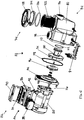
- FIGS. 3 and 4 illustrate the pump unit 22, according to one embodiment of the invention, including the pump 32, the pump controller 26, the user interface 24, and the motor 32 for use with the pumping system 10 described above.
- the pump 32 can be configured for use in any suitable aquatic application, including pools, spas, and/or water features.
- the pump 32 can include a housing 74 and can be connected to the motor 30.
- the motor 30 can be a variable speed motor, as described above, and the pump controller 26 can include a variable speed drive to drive the motor 30.
- the motor 30 can be driven at four or more different pre-set speeds.
- the housing 74 can include an inlet 76, an outlet 78, a basket 80, a lid 82, and a stand 84.
- the stand 84 can support the motor 30 and can be used to mount the pump 32 on a suitable surface (not shown).
- the pump controller 26 can be coupled to (e.g., physically attached or fastened to) the pump 32 and/or the motor 30.
- the pump controller 26 and the user interface 24 can be enclosed in a case 86 that can be mounted on the motor 30.
- the case 86 can include a field wiring compartment 88 and a cover 90.
- the cover 90 can be opened and closed to allow access to the pump controller 26 (and specifically, the user interface 24) and protect it from moisture, dust, and other environmental influences.
- the field wiring compartment 88 can include a power supply to provide power to the motor 30 and the pump controller 26.
- the motor 30 can include a coupling 92, as shown in FIG.
- the pump controller 26 and/or the user interface 24 can be removable from the motor 30 and/or the pump 32.
- the pump controller 26 and/or the user interface 24 can be configured for mounting to the motor 30, the pump 32, and/or a wall and can be removable so that the pump controller 26 and/or the user interface 24 can be removed and remounted the motor 30, the pump 32, and/or a wall if desired by a user.
- the pump 32 can include a seal plate 94, an impeller 96, a gasket 98, a diffuser 100, and a strainer 102.
- the strainer 102 can be inserted into the basket 80 and can be secured by the lid 82.
- the lid 82 can include a cap 104, an O-ring 106, and a nut 108.
- the cap 104 and the O-ring 106 can be coupled to the basket 80 by screwing the nut 108 onto the basket 80.
- the O-ring 106 can seal the connection between the basket 80 and the lid 82.
- An inlet 110 of the diffuser 100 can be fluidly sealed to the basket 80 with a seal 112.
- the diffuser 100 can enclose the impeller 96.
- An outlet 114 of the diffuser 100 can be fluidly sealed to the seal plate 94.
- the seal plate 94 can be sealed to the housing 74 with the gasket 98.
- the motor 30 can include a shaft 116, which can be coupled to the impeller 96. The motor 30 can rotate the impeller 96, drawing fluid from the inlet 46 through the strainer 72 and the diffuser 70 to the outlet 48 (i.e., to drive the pump 32).
- the inlet 76 and the outlet 78 of the pump 32 can be connected to the inlet line 46 and the outlet line 44, respectively, of the pumping system 10.
- FIG. 5A illustrates the user interface 24 for the pump controller 26 in accordance with one embodiment of the invention.
- the user interface 24 can include a display 118, at least one speed button 120, navigation buttons 122, a start-stop button 124, a reset button 126, a manual override button 128, and a "quick clean" button 130.
- the manual override button 128 can also be considered a "time out” button.
- the navigation buttons 122 can include a menu button 132, a select button 134, an escape button 136, an up-arrow button 138, a down-arrow button 140, a left-arrow button 142, a right-arrow button 144, and an enter button 146.
- the navigation buttons 122 and the speed buttons 120 can be used to program a schedule into the pump controller 26.
- the display 108 can include a lower section 148 to display information about a parameter and an upper section 150 to display a value associated with that parameter.
- the user interface 24 can include light emitting diodes (LEDs) 152 to indicate normal operation and/or a detected error of the pump 32.
- LEDs light emitting diodes
- FIG. 5B illustrates the control/automation system 20 according to one embodiment of the invention.
- the control/automation system 20 can communicate with the pump controller 26.
- the control/automation system 20 can control the pump 32 through a master/slave relationship with the pump controller 26.
- the control/automation system 20 can also be used to program the pump controller 26, for example, if the pump 32 is installed in a location where the user interface 24 is not conveniently accessible.
- the pump controller 26 can automatically operate the pump 32 according to at least one programmed schedule (for example, designating a speed or flow rate of the pump 32 and/or the motor 30 as well as a scheduled start time, a scheduled stop time, and/or a duration). If two or more schedules are programmed into the pump controller 26, the schedule running the pump 32 at the highest speed can have priority over the remaining schedules. In some embodiments, the pump controller 26 can allow manual operation of the pump 32. If the pump 32 is manually operated and is overlapping a scheduled run, the scheduled run can have priority over the manual operation independent of the speed of the pump 32.
- schedule for example, designating a speed or flow rate of the pump 32 and/or the motor 30 as well as a scheduled start time, a scheduled stop time, and/or a duration.
- the pump controller 26 can include a manual override (e.g., through the manual override or "time out” button 128).
- the manual override can interrupt the scheduled and/or manual operation of the pump 32 to allow for cleaning and maintenance procedures of the pool 12 for example.
- the pump controller 26 can monitor the operation of the pump 32 and can indicate abnormal conditions of the pump 32 and/or the pumping system 10, as discussed above.
- FIGS. 6A-6B illustrate a menu 154 for the pump controller 26 according to one embodiment of the invention.
- the menu 154 can be used to program various features of the pump controller 26.
- the menu 154 can include a hierarchy of categories 156, parameters 158, and values 160, any one of which can be displayed by the display 118 of the user interface 24 so that a user or installer can program the various features on the pump controller 26.
- an operator can enter the menu 154 by pressing the menu button 132.
- the operator can scroll through the categories 156 (i.e., so that the display visually scrolls through the menu 154) using the up-arrow button 138 and the down-arrow button 140.
- the categories 156 can include settings 164, speed 166, external control 168, features 170, priming 172, anti freeze 174, and flow lock 176 (in any order).
- the operator can enter a category 156 by pressing the select button 134.
- the operator can scroll through the parameters 158 within a specific category 156 using the up-arrow button 138 and the down-arrow button 140.
- the operator can select a parameter 158 by pressing the select button 134 and can adjust the value 160 of the parameter 158 with the up-arrow button 138 and/or the down-arrow button 140.
- the value 160 can be adjusted by a specific increment or the user can select from a list of options.
- the user can save the value 160 by pressing the enter button 146. By pressing the escape button 136, the user can exit the menu 154 without saving any changes.
- the settings category 164 can include a time setting 178, a minimum speed setting 180, a maximum speed setting 182, and a SVRS automatic restart setting 184, as well as other settings parameters 186.
- the time setting 178 can be used to run the pump 32 on a particular schedule.
- the minimum speed setting 180 and the maximum speed setting 182 can be adjusted according to the volume of the aquatic applications.
- An installer of the pump 32 can provide the minimum speed setting 180 and the maximum speed setting 182, for example, upon installation of the pump 32.
- the pump controller 26 can automatically prevent the minimum speed setting 180 from being higher than the maximum speed setting 182.
- the minimum and maximum speed settings 180, 182 can be set so that the pump 32 will not operate outside of these speeds in order to protect flow-dependent devices with minimum speeds and pressure-sensitive devices (e.g., filters) with maximum speeds.
- the SVRS automatic restart setting 184 can provide a time period before the pump controller 26 will resume normal operation of the pump 32 after an obstruction along the inlet line 46 (for example, at the main drain 38) has been detected and the pump 32 has been stopped, in accordance with a safety vacuum release system feature of the pumping system 10.
- there can be two minimum speed settings such as one for dead head detection (e.g., a higher speed) and one for dynamic detection (e.g., a lower speed), as described in United States Patent No. 8,313,306 (entitled "Method of Operating a Safety Vacuum Release System").
- the speed category 166 can be used to input data for running/operating the pump 32 manually and/or automatically (i.e., via programmed speed settings).
- the pump controller 26 can store a number of pre-set speeds/speed settings (such as eight).
- each of the first four speeds/speed settings in a first set of speeds 188 (“Speed 1-4") can be set as manual speeds, scheduled speeds (e.g., speeds with set start and stop times), and/or countdown/timer speeds (e.g., speeds with a time duration).
- Each of the second four speeds/speed settings in a second set of speeds 190 (“Speed 5-8") can be set scheduled speeds (e.g., speeds with set start and stop times).
- speeds 5-8 can be programmed to operate in a scheduled mode only, while speeds 1-4 can be programmed to operate in a manual, scheduled, or countdown mode.
- a speed can be programmed for the manual mode.
- a speed, a start time, and a stop time can be programmed for the scheduled modes.
- a speed and a duration can be programmed for the countdown timer mode.
- each speed setting can include a speed, a start time, a stop time, and/or a duration depending on the respective mode.
- the speeds/speed settings from both sets 188, 190 can be programmed into the pump controller 26 using the up-arrow button 138, the down-arrow button 140, and the enter button 146 to select the above-described values.
- the first set of speeds 188 (speeds 1-4) can be accessed by pressing one of the speed buttons 120 on the user interface 24.
- the schedule running the pump 32 at the highest speed can have priority over the remaining schedules.
- Not all of speeds 5-8 in the second set of speeds 162 must be programmed to run on a schedule. For example, one or more of speeds 5-8 can be disabled.
- the external control category 168 can include various programs 192 with speed settings that can run when commanded by the control/automation system 20.
- four programmed speeds can be included (i.e., programs 1-4). In one embodiment, these four programmed speeds can default at 1100 RPM, 1500 RPM, 2350 RPM, and 3110 RPM, respectively.
- Each program 192 can be accessible to individually set a new speed using the up-arrow button 138, the down-arrow button 140, and the enter button 146. In other embodiments, the number of programs 192 can be equal to the number of scheduled runs programmed in the second set of speeds 190 (speeds 5-8).
- the speed category 166 and the external control category 168 can alternatively be programmed with flow rates/flow rate settings instead of speeds/speed settings.
- the speed category 166 can have an additional mode parameter that allows a user to select a "flow control mode" (i.e., where flow rates are set) or a "speed control mode" (i.e., where speeds are set, as described above).
- flow rates can be set in accordance with the speed settings described above (e.g., where speeds 1-4, speeds 5-8, and/or externally controlled programmed speeds of the programs 192 are instead flows 1-4, flows 5-8, and/or externally controlled programmed flows of the programs 192).
- Flows 1-4 can be programmed to operate in a manual, scheduled, or countdown mode, flows 5-8 can be programmed to operate in a scheduled mode, and the externally controlled programmed flows can be programmed to operate in a scheduled mode.
- each flow rate setting can include a flow rate, a start time, a stop time, and/or a duration depending on the respective mode.
- Flows 1-4 can also be accessed or selected through the navigation buttons 92 on the user interface 88.
- the pumping system 10, and in particular the pump controller 26 can operate to maintain a constant pump speed (i.e., in the speed control mode) and/or can operate to maintain a constant flow rate of water within the fluid circuit, or across the filter 14 (i.e., in the flow control mode).
- the pump controller 26 continuously or periodically adjusts the speed of the motor 30 in order to maintain the set flow rates/flow rate settings. More specifically, the amount of water that can be moved and/or the ease by which the water can be moved is dependent in part upon the current state (e.g., quality, cleanliness) of the filter 14.
- a clean (e.g., new, fresh, or backwashed) filter 14 provides a lesser impediment to water flow than a filter that has accumulated filter matter (e.g., a dirty filter 14). Therefore, for a constant flow rate through a filter 14, a lesser pressure is required to move the water through a clean filter 14 than a pressure that is required to move the water through a dirty filter 14.
- Another way of considering the effect of dirt accumulation is that if pressure is kept constant, the flow rate will decrease as the dirt accumulates and hinders (e.g., progressively blocks) the flow. Maintenance of a constant flow volume despite an increasing impediment caused by filter dirt accumulation can require an increasing pressure and is the result of increasing force from the pump motor 30.
- Some embodiments of the invention control the pump 32, and more specifically control the speed of the pump motor 30, to provide the increased force that provides the increased pressure to maintain the constant flow.
- the pump controller 26 can determine flow rates based on power consumption of the motor and/or the speed of the motor.
- the pump controller 26 can execute one of the following flow control procedures. First, the pump controller 26 can determine (e.g., receive, obtain, or calculate) a current speed of the motor 30, determine a reference power consumption based on the current speed of the motor 30 and the programmed flow rate, and determine (e.g., receive, obtain, or calculate) the current power consumption of the motor 30.
- the pump controller 26 can then calculate a difference value between the reference power consumption and the current power consumption and use proportional (P), integral (I), and/or derivative (D) control (e.g., P, I, PI, PD, PID) based on the difference value to generate a new speed of the motor 30 that will achieve the programmed flow rate.
- the pump controller 26 can then adjust the current speed of the motor 30 to the new speed to maintain the programmed flow rate.
- the pump controller 26 can determine (e.g., receive, obtain, or calculate) a current speed of the motor 30, the current power consumption of the motor 30, and the current flow rate through the pumping system 10 (i.e., based on the current power consumption and/or the current speed).
- the pump controller 26 can then calculate a difference value between the reference power consumption and the current power consumption and use proportional, integral, and/or derivative control based on the difference value to generate a new speed of the motor 30 that will achieve the programmed flow rate.
- the pump controller 26 can then adjust the current speed of the motor 30 to the new speed to maintain the programmed flow rate.
- the pump controller 26 can execute the flow control procedures as described in United States Patent No. 7,845,913 , entitled "Flow Control".
- the ability to maintain a constant flow is useful to achieve a specific flow volume during a period of time. For example, as discussed above, it may be desirable to perform a specific number of turnovers within a predetermined time period, such as one day. The desired number of turnovers may be related to the necessity to maintain a desired water clarity, despite the fact that the filter of the pumping system will progressively increase dirt accumulation.
- flow rates change over time because the resistance, or total dynamic head (TDH), of the pumping system changes as dirt and debris accumulate in the filter and system strainers. This increase in flow resistance causes the conventional single speed pump to lose flow as the system gets dirty, enough so that desired turnovers are not achieved as a result of the loss of flow.
- TDH total dynamic head
- the features category 170 can be used to program a manual override.
- the parameters can include a "time out” program 194 and a "quick clean” program 196.
- the "time out” program 194 can interrupt the operation of the pump 32 and/or motor 30 for a certain amount of time, which can be programmed into the pump controller 26.
- the “time out” program 194 can be selected by pressing the "time out” button 128 on the user interface 24.
- the "time out” program 194 can be used to stop operation of the pump 32 so that a user can clean the pool or spa and/or to perform maintenance procedures.
- the "quick clean” program 196 can include a speed setting and a duration setting.
- the "quick clean” program 196 can be selected by pressing the "quick clean” button 130 located on the user interface 24. When pressed, the "quick clean” program 196 can have priority over the scheduled and/or manual operation of the pump 32. After the pump 32 has been operated for the time period of the duration setting, the pump 32 can resume to the scheduled and/or manual operation. If the SVRS has been previously triggered and the time period for the SVRS automatic restart 184 has not yet elapsed, the "quick clean” program 196 may not be initiated by the pump controller 26.
- the priming of the pump 32 can be enabled or disabled at setting 200.
- the priming sequence of the pump 32 can remove substantially all air in the pump 32 in order to allow water to flow through the pump 32 and/or the fluid circuit.
- a maximum duration for the priming sequence (“max priming time") can be programmed into the pump controller 26 at setting 202. This is the maximum duration that the pump 32 will try to prime before giving an error.
- the priming sequence can be run/driven at the maximum speed 182.
- the pump 32 can be run at a first speed (e.g., 1800 RPM) for a first duration (e.g., about three seconds). If there is sufficient flow through the pump 32, priming is completed.
- the pump 32 can be run at the maximum speed 182 for a priming delay time (such as about 20 seconds, set at setting 204). If there is sufficient flow through the pump 32 at this point, priming is completed. If not, the pump 32 can continue to be run at the maximum speed 182 for an amount of time set by the maximum priming time setting 202. If there is still not sufficient flow when the maximum priming time setting 202 has expired, a dry priming alarm can be reported (e.g., via the LEDs 152 and/or the display 118). In addition, a priming sensitivity value from 1% to 100% can be selected at setting 206. This priming sensitivity value affects the determination of whether flow is sufficient to consider priming completed. Lower sensitivity values increase the amount of flow needed for the pump 32 to sense that it is primed, while higher sensitivity values decrease the amount of flow needed for the pump 32 to sense that it is primed.
- a priming delay time such as about 20 seconds, set at setting 204.
- an internal temperature sensor of the pump 32 can be connected to the pump controller 26 in order to provide an anti-freeze operation for the pumping system 10 and the pump 32.
- an enable/disable setting 208 can be set to enable or disable the anti-freeze operation.
- a speed setting 210 and a temperature setting 212 at which the pump 32 can be activated to prevent water from freezing in the pumping system can be programmed into the pump controller 26. If the temperature sensor detects a temperature lower than the temperature setting 212, the pump 32 can be operated according to the speed setting 210.
- the internal temperature sensor can sense a temperature of the motor 30 and/or the variable speed drive of the pump controller 26.
- the internal temperature sensor can be embedded within a heat sink positioned between the pump controller/variable speed drive and the motor 30.
- the menu 154 can include the flow lock category 176 for the pump 32 to operate with a flow locking feature.
- this flow locking feature can allow a user to program a minimum and maximum flow rate into the pumping system 10 that cannot be changed, thereby "locking the flow.”
- this feature can be active when the pump 32 and the motor 30 are being controlled in the speed control mode in accordance with the speed settings described above (e.g., the first set of speeds 160, the second set of speeds 162, or the externally programmed speeds 164). This can allow the pump controller 26 to take flow rate and/or turnover rates into consideration even when operating to maintain pump speeds, as further described below.
- the flow locking feature can be active when the pump 32 and the motor 30 are being controlled in the flow control mode in accordance with one of the flow rate settings described above.
- the flow locking category 176 can include a "set min flow” setting 212, a "set max flow” setting 214, an "activation” setting 216, a "permanently lock flow” setting 218, a "min/max flow acceptable” setting 220, and an “enable/disable” setting 222.
- the minimum and maximum flow rates can be in a range from about 4,54 m 3 /h (20 gallons per minute (GPM)) to about 29,53 m 3 /h (130 GPM) or from about 4,54 m 3 /h (20GPM) GPM) to about 31,8 m 3 /h (140 GPM).
- the pump controller 26 can disable further resetting of these flow rates, as described above.
- a user can continue to input and reprogram speed settings or flow rate settings (e.g., of the first set of speeds or flow rates 188, the second set of speeds or flow rates 190, or the externally programmed speeds or flow rates 192).
- the pump controller 26 can continue to operate as described above (for example, selecting a programmed flow rate based on a manual or scheduled run, or selecting a programmed flow rate requiring a highest motor speed if multiple scheduled runs are to take place at the same time), but may only operate the pump 32 and/or the motor 30 as long as the selected flow rate is between the minimum and maximum flow rates.
- the flow locking feature when incorporating the flow locking feature, users can still have the ability to change scheduled or manual speeds and/or flow rates for different needs (e.g., water features, spa jets, cleaners, etc.), but the flow locking feature can prevent the user from programming a flow that could exceed a "safe" flow rate of the pumping system 10.
- the flow locking feature can allow the pump controller 26 to control speed and/or flow of a pump 32, but still prevent the pump 32 from exceeding the set maximum or minimum flow rates.
- the flow locking feature can prevent programming or setting of flow rates of the first set of flow rates 188 and the second set of flow rates (e.g., by a user via the user interface 24 of the pump controller 24) that are outside of minimum/maximum flow rates.
- a user may be allowed to program flow rates of the externally programmed flow rates 192 (e.g., via the control/automation system 20) that are outside of the minimum/maximum flow rates.
- the flow locking feature causes the pump controller 26 to override these flow rates in order to operate the pump 32 to achieve the maximum flow rate (i.e., if the externally programmed flow rate 192 is above the maximum flow rate) or the minimum flow rate (i.e., if the externally programmed flow rate 192 is below the minimum flow rate).
- the pump controller 26 within the master/slave relationship between the control/automation system 20 and the pump controller 26, the pump controller 26 (specifically, the flow locking feature) always maintains control over the minimum and maximum flow rates of the pumping system 10 despite being the slave controller.
- the flow locking feature can allow programming or setting of speeds of the first set of speeds 188 and the second set of speeds 190 (e.g., by a user via the user interface 24 of the pump controller 24), and of speeds of the externally programmed speeds 192 (e.g., via the control/automation system 20) that can achieve flow rates outside the minimum and maximum flow rates (i.e., below and above the minimum and maximum flow rates, respectively).
- the flow locking feature causes the pump controller 26 to alter these speeds in order to operate the pump 32 between the maximum flow rate and the minimum flow rate.
- a user can program speeds that would cause the pump 32 to operate outside of the minimum or maximum flow rate, but the pump controller 26 does not allow the pump to operate at the programmed speeds if this is the case. Rather, if the programmed speed were to result in a flow rate below the minimum flow rate or above the maximum flow rate, the pump controller 26 adjusts the speed until the resulting flow rate is at the minimum flow rate or at the maximum flow rate, respectively.
- the pump controller 26 can then continuously monitor a current state of the pump system 10 (in particular, of the filter 14), in order to determine a pump motor speed necessary to achieve the maximum flow rate of 18,17 m 3 /h (80GPM) and then set this pump motor speed as an upper speed limit. For example, the pump controller 26 can first determine that, based on the current state of the pump system 10, a pump motor speed of 3000 RPM is necessary to achieve the maximum flow rate of 18,17 m 3 /h (80 GPM) (e.g., using the flow control procedures described above), thereby setting 3000 RPM as the upper speed set point.
- the pump controller 26 is then programmed by a user in a speed control mode to operate the pump motor 30 at a speed of 3400 RPM. Due to the flow locking feature, the pump controller 26 will not operate the pump motor 30 at the 3400 RPM speed, but rather will only go up to the upper speed set point (i.e., 3000 RPM). Thus, the pump controller 26 will alter the programmed speed to maintain the flow rate at or under the maximum flow rate. Later, if the TDH in the pumping system 10 increases and the pump controller 26 determines that the pump motor 30 now requires a speed of 3150 RPM to generate a flow rate 18,17 m 3 /h (80 GPM), the pump controller 26 sets the upper speed set point to 3150 RPM and increases the motor speed to 3150 RPM.
- the pump controller 26 continuously or periodically monitors the pumping system 10 and, if a programmed speed were to exceed the maximum flow rate, the pump controller 26 operates the motor 30 at the highest allowable speed below the programmed speed that achieves the maximum flow rate (i.e., at the upper speed set point) so that the pumping system 10 does not exceed the maximum flow rate.
- an installer enables the flow locking feature and sets the minimum flow rate at 18,17 m 3 /h (80 GPM).
- the pump controller 26 can then continuously monitor a current state of the pump system 10 in order to determine a pump motor speed necessary to achieve the minimum flow rate of 18,17 m 3 /h (80 GPM), and then set this pump motor speed as a lower speed limit.
- the pump controller 26 can first determine that, based on the current state of the pump system 10, a pump motor speed of 3000 RPM is necessary to achieve the minimum flow rate of 18,17 m 3 /h (80 GPM), thereby setting 3000 RPM as the lower speed set point.
- the pump controller 26 is then programmed by a user in a speed control mode to operate the pump motor 30 at a speed of 2900 RPM. Due to the flow locking feature, the pump controller 26 will not operate the pump motor 30 at the 2900 RPM speed, but rather will only drop down to the lower speed set point (i.e., 3000 RPM). Thus, the pump controller 26 will alter the programmed speed to maintain the flow rate at or above the minimum flow rate. Later, if the TDH in the pumping system 10 increases and the pump controller 26 determines that the pump motor 30 now requires a speed of 3150 RPM to generate a flow rate 18,17 m 3 /h (80 GPM), the pump controller 26 sets the lower speed set point to 3150 RPM and increases the motor speed to 3150 RPM.
- the pump controller 26 continuously or periodically monitors the pumping system 10 and, if a programmed speed were to exceed (i.e., go below) the minimum flow rate, the pump controller 26 operates the motor 30 at the lowest allowable speed above the programmed speed that achieves the minimum flow rate (i.e., at the lower speed set point) so that the pumping system 10 does not drop below the minimum flow rate.
- an installer enables the flow locking feature and sets the maximum flow rate at 18,17 m 3 /h (80 GPM) and the minimum flow rate at 9.08 m 3 /h (40 GPM).
- a user would not be allowed to program a flow rate in the pump controller menu 154 above 18,17 m 3 /h (80 GPM) or below 9.08 m 3 /h (40 GPM).
- the pump controller 26 is connected to the control/automation system 20, the user can program, via the control/automation system 20, a flow rate above 18,17 m 3 /h (80 GPM) or below 9.08 m 3 /h (40 GPM).
- the pump controller 26 would override the programmed flow rate to operate the at 18,17 m 3 /h (80 GPM) (i.e., if the programmed flow rate was above 18,17 m 3 /h (80 GPM) or at 9.08 m 3 /h (40 GPM) (i.e., if the programmed flow rate was below 9.08 m 3 /h (40 GPM)).
- a user In the speed control mode, a user would be allowed to program speeds exceeding those that would create flow rates above 18,17 m 3 /h (80 GPM) or below 9.08 m 3 /h (40 GPM) either through the pump controller menu 154 or through the control/automation system 20, but the pump controller 26 would alter the programmed speed to maintain a flow rate of 18,17 m 3 /h (80 GPM) (i.e., if the programmed speed would cause a flow rate above 18,17 m 3 /h (80 GPM)) or a flow rate of 9.08 m 3 /h (40 GPM) (i.e., if the programmed speed would cause a flow rate below 9.08 m 3 /h (40 GPM)).
- FIG. 7 illustrates an example of the user interface 24 during a flow control mode when the flow locking feature is activated.
- the display 128 shows the upper section 150 including a "password locked" key (indicating that access to programming the pump controller 26 is password protected), indications that the pumping system 10 is enabled with SVRS and flow locking ("FloLock") features, a current time, and a current flow rate.
- the lower section 148 indicates current power consumption as well as the minimum and maximum flow rates set through the flow locking feature.
- the pump controller 26 can still ensure that the flow rate for a desired turnover is met as conditions in the pumping system 10 change. More specifically, the pump controller 26 can detect, monitor, and maintain the flow rate by automatically adjusting the speed of the pump 32 as these conditions change (i.e., as the current state of the pumping system 10 changes), while also taking into consideration the set maximum and minimum flow rates. In other words, locking a maximum speed or flow rate may basically control how much water a pump 32 can move, but the flow rate can still be adjusted as the total dynamic head (TDH) of a pumping system 10 changes.
- TDH total dynamic head
- An advantage of the flow locking feature is that an installer locks in an actual flow rate and the pump controller 26 can monitor the pumping system 10 for changes in TDH that affect flow rate, self adjust to maintain a specified flow rate, and still maintain the pumping system 10 within the set maximum and minimum flow rates.
- the minimum flow rate set by the flow locking feature can ensure a health department that a municipality will not slow the flow of the pump 32 down below commercial turnover standards (either for 24-hour time periods or shorter time periods).
- the flow locking feature can make variable speed technology more dependable and acceptable for use in commercial swimming pool applications.
- the maximum flow rate set by the flow locking feature can prevent the pump 32 from running at a flow rate that could exceed the flow rate specification of pool system components, such as a drain cover.
- the flow locking feature can decrease the chance of an entrapment issue occurring by setting the maximum flow rate as the flow rate defined by local codes and the drain cover. Further, the maximum set flow rate can prevent a pipe between two drains from exceeding a velocity which would allow a "hold down" vacuum to be created on a covered drain. The maximum flow rate setting can also ensure that the flow rate of the pump 32 does not exceed what is recommended by energy efficiency codes.
Landscapes
- Engineering & Computer Science (AREA)
- Mechanical Engineering (AREA)
- General Engineering & Computer Science (AREA)
- Health & Medical Sciences (AREA)
- Public Health (AREA)
- Computer Hardware Design (AREA)
- Epidemiology (AREA)
- Pain & Pain Management (AREA)
- Physical Education & Sports Medicine (AREA)
- Rehabilitation Therapy (AREA)
- Life Sciences & Earth Sciences (AREA)
- Animal Behavior & Ethology (AREA)
- General Health & Medical Sciences (AREA)
- Veterinary Medicine (AREA)
- Control Of Non-Positive-Displacement Pumps (AREA)
Description
- This application claims priority under 35 U.S.C. § 119 to United States Provisional Patent Application No.
61/554,439 filed on November 1, 2011 - Conventional pool pumps are operable at a finite number of predetermined speed settings. These speed settings correspond to the range of pumping demands of the pool at the time of installation. Factors such as the volumetric flow rate of water to be pumped, the total head pressure required to adequately pump the volume of water, and other operational parameters determine the size of the pump and the proper speed settings for pump operation. Once the pump is installed, the speed settings may not be readily changed to accommodate changes in the pool conditions and/or pumping demands. For example, flow rates through these pumps change over time because the system's total dynamic head changes as dirt and debris accumulate in the pool filter and strainers. This increase in flow resistance causes the conventional pumps to lose flow as the system gets dirty. Due to this loss of flow and the inability to adjust settings, such systems may not maintain desired turnover rates in the pool. As a result, such systems fail to meet health department requirements for commercial swimming pool applications, which require a minimum number of turnovers per day.
- Newer pool pump systems include variable speed drives, allowing them to operate at any number of speeds to maintain the above-described factors independent of changes in the pool conditions and/or pumping demands. These pumps are controlled to run at different speeds and flows to maintain one or more control factors and to accommodate changing water supply needs of a pool, such as periodic operation of a water feature. Current control of such systems only focuses on a number of manual and/or scheduled operations, programmable by a pool user, and generally may not consider overall flow or turnover parameters.
-
US2010308963 A1 discloses a variable frequency drive system and a method of controlling a pump driven by a motor with the pump in fluid communication with a fluid system. The drive system and method can provide one or more of the following: a sleep mode, pipe break detection, a line fill mode, an automatic start mode, dry run protection, an electromagnetic interference filter compatible with a ground fault circuit interrupter, two-wire and three-wire and three-phase motor compatibility, a simple start-up process, automatic password protection, a pump out mode, digital input/output terminals, and removable input and output power terminal blocks. -
US2008168599 A1 discloses a water circulating system, such as a spa system, having a flow control feature. The spa system includes a tub, a pump assembly and a controller. The pump assembly includes a BLDC motor and circulates water from the tub's outlet port to its inlet port. The controller sets the speed of the BLDC motor to any speed within the speed range of the BLDC motor in response to a user input to adjust the flow rate of the water to the inlet port of the tub. The spa system may also produce at least one jetting mode in response to a user input. The jetting mode may be a pulse mode, a sinusoidal mode, a ramp mode, or a saw-tooth mode. In another spa system, a first pump operates at a first speed to heat the circulating water when a heater is activated, and at a second speed when the heater is not activated. The spa system includes a jetting pump assembly that includes a BLDC motor and a circulating pump assembly that operates at two speeds. The spa system includes a circulating pump assembly that circulates water from an outlet port to an inlet port during standby. Where the circulating pump assembly operates at a first speed when a heater is activated to heat the circulating water, and at a second speed when the heater is not activated. -
US2009093774 A1 discloses an ambulatory medical fluid delivery system, which may comprise a fluid flow path for communicating between a source and a patient. The system may also comprise a reusable controller, which may be operable to control fluid flow in the path and include a module interface station, and a disposable fluid flow delivery set, which may include a flow control module adapted to be removably received by the module interface station. Such flow control module may include a flow valve which is operably associated with the path. Such valve may be operably controlled by the reusable controller in response to sensed flow rates of fluid flow in such path. Alternatively an ambulatory reusable controller is provided for use with a disposable medical fluid flow delivery set. It may further alternatively include a differential pressure sensing device. -
US5935099 A discloses a menu driven reprogrammable drug pump with a memory, such as flash memory, a display, a keyboard, and a communications port to allow a generic pump to be programmed with a desired pump application (therapy) program and patient specific settings. Programming and data transfer with another pump or a computer to and from the patient pump is by the communications port that allows local and/or remote communications with the pump. Flash memory stores the pump application program during use. Patient safety is provided by a cassette identification system, an occlusion detection system, and a latch/lock detection system. Automated testing of the pump is by a closed loop testing system. -
US5755563 A discloses an apparatus and method for controlling a flow parameter of a pump. The pump includes a pumping device for pumping fluid, the pumping device having at least one flow parameter. The pump further includes a control coupled to the pumping device and a control panel having a plurality of controls operable by a human. The control is programmable by operation of the plurality of controls, thereby allowing a human to program the at least one flow parameter of said pumping device by operation of the plurality of controls. The control has a lock that can be activated by operation of at least two of the plurality of controls. Upon activation, the lock prevents the alteration of the at least one flow parameter. The method includes the step of providing the pump of the present invention, programming the at least one flow parameter by operating the plurality of controls, and activing the lock by operating at least two of the plurality of controls. - An aspect of the present disclosure provides a pumping system for at least one aquatic application as defined in
claim 1. - The invention provides a pumping system for at least one aquatic application including a pump, a motor coupled to the pump, and a pump controller in communication with the motor. The pump controller includes a user interface configured to initially receive and set a maximum locked flow rate, a minimum locked flow rate, and a plurality of programmed flow rate settings including a first programmed flow rate setting. The pump controller is also configured to disable resetting of the maximum flow rate and the minimum flow rate once they are initially received and set through the user interface and to allow resetting of the plurality of programmed flow rate settings throughout operation of the pumping system. The pump controller is further configured to operate the motor in order to maintain a first flow rate through the pumping system set by the first programmed flow rate setting as long as the first flow rate is between the minimum locked flow rate and the maximum locked flow rate.
-
-
FIG. 1 is a block diagram of a variable speed pumping system in a pool environment in accordance with one embodiment of the invention. -
FIG. 2 is a schematic illustration of example auxiliary devices that can be operably connected to a control/automation system of the variable speed pumping system ofFIG. 1 . -
FIG. 3 is a perspective view of a pool pump for use in one embodiment of the invention. -
FIG. 4 is an exploded perspective view of the pool pump ofFIG. 3 . -
FIG. 5A is a front view of a user interface of a pump controller for use with the pool pump ofFIG. 1 . -
FIG. 5B is a perspective view of a control/automation system for use with the variable speed pumping system ofFIG. 1 . -
FIGS. 6A-6B illustrate a flow chart of menu settings of the pump controller ofFIG. 5A according to one embodiment of the invention. -
FIG. 7 is another front view of a user interface of a pump controller for use with the pool pump ofFIG. 3 . - Before any embodiments of the invention are explained in detail, it is to be understood that the invention is not limited in its application to the details of construction and the arrangement of components set forth in the following description or illustrated in the following drawings. The invention is capable of other embodiments and of being practiced or of being carried out in various ways. Also, it is to be understood that the phraseology and terminology used herein is for the purpose of description and should not be regarded as limiting. The use of "including," "comprising," or "having" and variations thereof herein is meant to encompass the items listed thereafter and equivalents thereof as well as additional items. Unless specified or limited otherwise, the terms "mounted," "connected," "supported," and "coupled" and variations thereof are used broadly and encompass both direct and indirect mountings, connections, supports, and couplings. Further, "connected" and "coupled" are not restricted to physical or mechanical connections or couplings.
- The following discussion is presented to enable a person skilled in the art to make and use embodiments of the invention. Various modifications to the illustrated embodiments will be readily apparent to those skilled in the art, and the generic principles herein can be applied to other embodiments and applications without departing from embodiments of the invention. Thus, embodiments of the invention are not intended to be limited to embodiments shown, but are to be accorded the widest scope consistent with the principles and features disclosed herein. The following detailed description is to be read with reference to the figures, in which like elements in different figures have like reference numerals. The figures, which are not necessarily to scale, depict selected embodiments and are not intended to limit the scope of embodiments of the invention. Skilled artisans will recognize the examples provided herein have many useful alternatives and fall within the scope of embodiments of the invention.
-
FIG. 1 illustrates a schematic of a variable-speed pumping system 10, according to one embodiment of the invention, in connection with apool 12. Thepumping system 10 can include afilter 14, aheat pump 16, achlorinator 18, a control/automation system 20, and apump unit 22 with auser interface 24, apump controller 26 including a variable speed drive (VSD) 28, amotor 30, and apump 32. Thepool 12 can be any aquatic application including, but not limited to, a commercial or residential swimming pool, spa, and/or whirlpool bath, and can include awater feature 34 including one or more waterfalls, spillways, etc., amain return 36 including one or more pool inlets, a main drain 38 including one or more drains, askimmer drain 40, and/or asuction cleaner 42. Theskimmer drain 40 can collect coarse debris from water being withdrawn from thepool 12 and thesuction cleaner 42 can be a manual or automatic pool cleaner and can vacuum debris from various submerged surfaces of thepool 12. - Water can be circulated through the
pool 12 by thepumping system 10 through anoutlet line 44 connected to thewater feature 34 and/or the main return 36 (e.g., supplying water to the pool 12) and aninlet line 46 connected to theskimmer drain 40, thesuction cleaner 42, and/or the main drain 38 (e.g., receiving or withdrawing water from the pool 12). More specifically, as shown inFIG. 1 , thepump 32 can move water from theinlet line 46 to theoutlet line 44, and thefilter 14, theheat pump 16, and thechlorinator 18 can be connected between thepump 32 and theoutlet line 44 to treat the water before it is supplied back to thepool 12. As a result, the pool components receiving water (i.e., theskimmer drain 40, thesuction cleaner 42, and/or the main drain 38), thepump 32, thefilter 14, theheat pump 16, thechlorinator 18, and the pool components supplying water (i.e., thewater feature 34 and/or the main return 38) form a fluid circuit or pathway, as designated by solid line connections inFIG. 1 , for circulating water through thepool 12. In some embodiments, some pool components, such as thewater feature 34 and/or thesuction cleaner 42, are capable of being shut off manually or automatically so that they do not supply water to or receive water from the pool 12 (e.g., so that they are no longer part of the fluid circuit). In addition, in some embodiments, components such as theheat pump 16 and/or thechlorinator 18 may not be included within thepumping system 10 and the fluid circuit. - Components of the
pumping system 10 can be connected through fluid connections (i.e., designated by solid lines inFIG. 1 ), and/or mechanical or electrical connections (i.e., designated by dashed lines inFIG. 1 ). With respect to thepump unit 22, thepump 32 can be a centrifugal pump and can be driven by thepump motor 30, such as a permanent magnet motor, an induction motor, a synchronous motor, or an asynchronous motor. The pump motor operation can be infinitely variable within a range of operations (i.e., zero to maximum operation). In the case of asynchronous motor 30, the steady state speed of the motor 30 (in rotations per minute, or RPM) can be referred to as the synchronous speed. Further, in the case of asynchronous motor 30, the steady state speed of themotor 30 can also be determined based upon the operating frequency in hertz (Hz). Thepump controller 26 can control thepump motor 30 and thus control thepump 32. Thepump controller 26 can include thevariable speed drive 28, which can provide infinitely variable control of the pump motor 30 (i.e., can vary the speed of the pump motor 30). Regarding operation of thevariable speed drive 28, a single phase AC current from a source power supply can be converted into a three-phase AC current. Thevariable speed drive 28 can supply the three-phase AC electric power at a changeable frequency to thepump motor 30 in order to drive thepump motor 30. For example, thepump controller 26 and thevariable speed drive 28 can operate themotor 30 as described in United States Patent No.7,857,600 , entitled "Pump Controller System and Method". - The
pump controller 26 can receive input from auser interface 24 in communication with the pump controller 26 (e.g., through physical or wireless connections). In addition, thepump controller 26 can be coupled to, such as physically attached or connected to, thepump 32 and/or themotor 30. In some embodiments, thepump controller 26 can control thepump 32 based on input from theuser interface 24 as well as input or feedback from themotor 30. More specifically, the pump controller can monitor one or more performance values or characteristics of thepumping system 10 based on input from themotor 30 and can control themotor 30, and thus thepump 32, based on the monitored values or characteristics, thereby providing a feedback loop for controlling themotor 30. Various parameters (e.g., that are calculated, provided via a look-up table, graph or curve, such as a constant flow curve, etc.) can be used to determine the performance characteristics, such as input power consumed by themotor 30, motor speed, flow rate and/or flow pressure. - For example, in some embodiments, physical sensors are not used to sense the pressure and/or flow rate in the
pumping system 10. Rather, motor power consumption (e.g., current draw) is used to monitor the performance of themotor 30 and thepump 32. Since the power consumption of themotor 30 has a relationship to the flow rate and pressure through thepump 32, pressure and/or flow rate can be calculated or determined allowing sensor-less control of themotor 30 and thepump 32. In other words, motor power consumption can be used to determine flow rate or pressure instead of using flow rate sensors or pressure sensors in locations throughout thepumping system 10. In addition, in some embodiments, thepump controller 26 can repeatedly monitor the motor 30 (such as the input power consumed by or the speed of the motor 30) to sense or determine an obstruction within the fluid circuit (e.g., along the inlet line upstream from the pump or along the outlet line downstream from the pump). For example, with respect to monitoring themotor 30 to sense or determine an obstruction, thepump controller 26 can operate in accordance with that described in United States Patent No.8,313,306 (entitled "Method of Operating a Safety Vacuum Release System") and United States Patent Publication No.2007/0183902 (entitled "Anti-Entrapment and Anti-Dead Head Function"). - The
pump controller 26 can also be connected to the control/automation system 20, for example in a manner to enable two-way communication between thepump controller 26 and the control/automation system 20. The control/automation system 20 can be an analog or digital control system that can include programmable logic controllers (PLC), computer programs, or the like that are pre-configured for controlling thepump 32. In some embodiments, thepump controller 26 and the control/automation system 20 can operate according to a master/slave relationship. For example, when thepump controller 26 is not connected to the control/automation system 20, thepump controller 26 can automatically control all functions of thepump unit 22. However when the control/automation system 20 is connected to thepump controller 26, the control/automation system 20 can automatically operate as a master controller and thepump controller 26 can automatically operate as a slave controller. In this manner, the master controller (i.e., the control/automation system 20) can have control over certain functions of the slave controller (i.e., the pump controller 26), such as functions related to optimization of energy consumption of themotor 30. As a result, the master controller can control the slave controller to operate thepump motor 30 and thepump 32 in a way to optimize energy consumption of themotor 30 or perform other operations specified by the user. - In some embodiments, the control/
automation system 20 can be operably connected to or in communication with one or more auxiliary devices in order to operate the auxiliary devices and/or receive input or feedback from the auxiliary devices. As shown inFIGS. 1 and2 , the auxiliary devices can include various mechanical, electrical, and/or chemical devices including, but not limited to, the pump unit 22 (e.g., via thepump controller 26, as described above), thefilter 14, theheat pump 16, thechlorinator 18 and/or another chemical dispersion device (not shown), thewater feature 34, thesuction cleaner 42, awater heater 48, one ormore lighting devices 50, a remote keypad 52 (e.g., including a user interface, such as akeypad 54, buttons, touch screen, etc., for receiving user input and/or a display 56), asecond pump 58 and/or asecond pump motor 60, one ormore sensors 62 associated with thepool 12 or thepumping system 10, one or more electrical ormechanical relays 64 orswitches 66 associated with thepool 12 or thepumping system 10, one or more electrically or mechanically operatedwater valves 68 associated with thepool 12 or thepumping system 10, an electrical ormechanical timing device 70, and/or apersonal computer 72. Connections between the control/automation system 20 and the auxiliary devices can be wired or wireless and can enable two-way communication between the control/automation system 20 and the auxiliary devices. For example, theremote keypad 54 can be a wireless keypad positioned away from the control/automation system 20 and/or thepump controller 26. In another example, thepersonal computer 72 can be connected to the control/automation system 20 through a wired or wireless computer network, such as a local area network. In addition, in some embodiments, one or more of the auxiliary devices can be connected to thepump controller 26 rather than the control/automation system 20, for example through a communications panel or junction box (not shown). - Two-way communication between the control/
automation system 20 and the auxiliary devices (or thepump controller 26 and the auxiliary devices) can allow for control of themotor 30, and thus thepump 32, based on input or feedback from the auxiliary devices. More specifically, inputs from the auxiliary devices, such as a desired flow rate necessary for operation of thewater heater 48, a user input from theremote keypad 52, etc., can be used to control operation of themotor 30 and thepump 32. Other parameters used by the control/automation system 20 (and/or the pump controller 26) for controlling operation of thepump motor 30 and thepump 32 can include, but are not limited to, water flow rate, water pressure, motor speed, and power consumption, as discussed above, as well as filter loading, chemical levels, water temperature, alarms, operational states, time, energy cost, turnovers per day, relay or switch positions, and/or other parameters (e.g., sensed, determined, calculated, obtained, etc.) that indicate performance of thepumping system 10. - In a general example, information entered into the
remote keypad 52 by a user can be received by the control/automation system 20, and the control/automation system 20 (i.e., acting as the master controller) can control the pump controller 26 (i.e., acting as the slave controller) to operate themotor 30 and thepump 32 based on the input information. The control/automation system 20 can also provide information back to theremote keypad 52 to display to the user, for example via thedisplay 56. In a more specific example with respect to turnovers per day, the pumping system 10 (i.e., the control/automation system 20 and/or the pump controller 26) can be preconfigured to permit a user to input, via theuser interface 24 or theremote keypad 52, a desired number of turnovers (i.e., number of times water is re-circulated through the fluid circuit). The control/automation system 20 and/or thepump controller 26 can then operate themotor 30 and thepump 32 to perform the desired number of turnovers within a predetermined amount of time, such as a 24-hour period. In another example, the control/automation system 20 can receive information from one or more auxiliary devices that thewater heater 48 is operating or needs to operate, and can alter the performance of the pumping system 10 (e.g., alter a speed of the pump motor 30) to provide an increased flow rate necessary for proper operation of thewater heater 48. -
FIGS. 3 and4 illustrate thepump unit 22, according to one embodiment of the invention, including thepump 32, thepump controller 26, theuser interface 24, and themotor 32 for use with thepumping system 10 described above. Thepump 32 can be configured for use in any suitable aquatic application, including pools, spas, and/or water features. Thepump 32 can include ahousing 74 and can be connected to themotor 30. In some embodiments, themotor 30 can be a variable speed motor, as described above, and thepump controller 26 can include a variable speed drive to drive themotor 30. In one embodiment, themotor 30 can be driven at four or more different pre-set speeds. Thehousing 74 can include aninlet 76, anoutlet 78, abasket 80, alid 82, and astand 84. Thestand 84 can support themotor 30 and can be used to mount thepump 32 on a suitable surface (not shown). - In some embodiments, the
pump controller 26 can be coupled to (e.g., physically attached or fastened to) thepump 32 and/or themotor 30. For example, as shown inFIGS. 3 and4 , thepump controller 26 and theuser interface 24 can be enclosed in acase 86 that can be mounted on themotor 30. Thecase 86 can include afield wiring compartment 88 and acover 90. Thecover 90 can be opened and closed to allow access to the pump controller 26 (and specifically, the user interface 24) and protect it from moisture, dust, and other environmental influences. In some embodiments, thefield wiring compartment 88 can include a power supply to provide power to themotor 30 and thepump controller 26. In addition, themotor 30 can include acoupling 92, as shown inFIG. 4 , to connect to thepump controller 26. In other embodiments, thepump controller 26 and/or theuser interface 24 can be removable from themotor 30 and/or thepump 32. For example, in such embodiments, thepump controller 26 and/or theuser interface 24 can be configured for mounting to themotor 30, thepump 32, and/or a wall and can be removable so that thepump controller 26 and/or theuser interface 24 can be removed and remounted themotor 30, thepump 32, and/or a wall if desired by a user. - As shown in
FIG. 4 , thepump 32 can include aseal plate 94, an impeller 96, agasket 98, adiffuser 100, and astrainer 102. Thestrainer 102 can be inserted into thebasket 80 and can be secured by thelid 82. In some embodiments, thelid 82 can include acap 104, an O-ring 106, and anut 108. Thecap 104 and the O-ring 106 can be coupled to thebasket 80 by screwing thenut 108 onto thebasket 80. The O-ring 106 can seal the connection between thebasket 80 and thelid 82. Aninlet 110 of thediffuser 100 can be fluidly sealed to thebasket 80 with aseal 112. In some embodiments, thediffuser 100 can enclose the impeller 96. Anoutlet 114 of thediffuser 100 can be fluidly sealed to theseal plate 94. Theseal plate 94 can be sealed to thehousing 74 with thegasket 98. Themotor 30 can include ashaft 116, which can be coupled to the impeller 96. Themotor 30 can rotate the impeller 96, drawing fluid from theinlet 46 through thestrainer 72 and thediffuser 70 to the outlet 48 (i.e., to drive the pump 32). With respect to thepumping system 10 ofFIG. 1 , theinlet 76 and theoutlet 78 of thepump 32 can be connected to theinlet line 46 and theoutlet line 44, respectively, of thepumping system 10. -
FIG. 5A illustrates theuser interface 24 for thepump controller 26 in accordance with one embodiment of the invention. Theuser interface 24 can include adisplay 118, at least onespeed button 120,navigation buttons 122, a start-stop button 124, areset button 126, amanual override button 128, and a "quick clean"button 130. Themanual override button 128 can also be considered a "time out" button. In some embodiments, thenavigation buttons 122 can include amenu button 132, aselect button 134, anescape button 136, an up-arrow button 138, a down-arrow button 140, a left-arrow button 142, a right-arrow button 144, and anenter button 146. Thenavigation buttons 122 and thespeed buttons 120 can be used to program a schedule into thepump controller 26. In some embodiments, for example, thedisplay 108 can include alower section 148 to display information about a parameter and anupper section 150 to display a value associated with that parameter. In some embodiments, theuser interface 24 can include light emitting diodes (LEDs) 152 to indicate normal operation and/or a detected error of thepump 32. -
FIG. 5B illustrates the control/automation system 20 according to one embodiment of the invention. As discussed above, the control/automation system 20 can communicate with thepump controller 26. Furthermore, as discussed above, the control/automation system 20 can control thepump 32 through a master/slave relationship with thepump controller 26. The control/automation system 20 can also be used to program thepump controller 26, for example, if thepump 32 is installed in a location where theuser interface 24 is not conveniently accessible. - In some embodiments, generally, the
pump controller 26 can automatically operate thepump 32 according to at least one programmed schedule (for example, designating a speed or flow rate of thepump 32 and/or themotor 30 as well as a scheduled start time, a scheduled stop time, and/or a duration). If two or more schedules are programmed into thepump controller 26, the schedule running thepump 32 at the highest speed can have priority over the remaining schedules. In some embodiments, thepump controller 26 can allow manual operation of thepump 32. If thepump 32 is manually operated and is overlapping a scheduled run, the scheduled run can have priority over the manual operation independent of the speed of thepump 32. In some embodiments, thepump controller 26 can include a manual override (e.g., through the manual override or "time out" button 128). The manual override can interrupt the scheduled and/or manual operation of thepump 32 to allow for cleaning and maintenance procedures of thepool 12 for example. Furthermore, in some embodiments, thepump controller 26 can monitor the operation of thepump 32 and can indicate abnormal conditions of thepump 32 and/or thepumping system 10, as discussed above. - More specifically,
FIGS. 6A-6B illustrate amenu 154 for thepump controller 26 according to one embodiment of the invention. In some embodiments, themenu 154 can be used to program various features of thepump controller 26. For example, themenu 154 can include a hierarchy ofcategories 156,parameters 158, and values 160, any one of which can be displayed by thedisplay 118 of theuser interface 24 so that a user or installer can program the various features on thepump controller 26. For example, from amain screen 162 on thedisplay 118, an operator can enter themenu 154 by pressing themenu button 132. The operator can scroll through the categories 156 (i.e., so that the display visually scrolls through the menu 154) using the up-arrow button 138 and the down-arrow button 140. In some embodiments, thecategories 156 can includesettings 164,speed 166,external control 168, features 170, priming 172,anti freeze 174, and flow lock 176 (in any order). In some embodiments, the operator can enter acategory 156 by pressing theselect button 134. The operator can scroll through theparameters 158 within aspecific category 156 using the up-arrow button 138 and the down-arrow button 140. The operator can select aparameter 158 by pressing theselect button 134 and can adjust thevalue 160 of theparameter 158 with the up-arrow button 138 and/or the down-arrow button 140. In some embodiments, thevalue 160 can be adjusted by a specific increment or the user can select from a list of options. The user can save thevalue 160 by pressing theenter button 146. By pressing theescape button 136, the user can exit themenu 154 without saving any changes. - In some embodiments, the
settings category 164 can include a time setting 178, a minimum speed setting 180, a maximum speed setting 182, and a SVRS automatic restart setting 184, as well asother settings parameters 186. The time setting 178 can be used to run thepump 32 on a particular schedule. The minimum speed setting 180 and the maximum speed setting 182 can be adjusted according to the volume of the aquatic applications. An installer of thepump 32 can provide the minimum speed setting 180 and the maximum speed setting 182, for example, upon installation of thepump 32. Thepump controller 26 can automatically prevent the minimum speed setting 180 from being higher than the maximum speed setting 182. The minimum andmaximum speed settings pump 32 will not operate outside of these speeds in order to protect flow-dependent devices with minimum speeds and pressure-sensitive devices (e.g., filters) with maximum speeds. The SVRS automatic restart setting 184 can provide a time period before thepump controller 26 will resume normal operation of thepump 32 after an obstruction along the inlet line 46 (for example, at the main drain 38) has been detected and thepump 32 has been stopped, in accordance with a safety vacuum release system feature of thepumping system 10. In some embodiments, there can be two minimum speed settings, such as one for dead head detection (e.g., a higher speed) and one for dynamic detection (e.g., a lower speed), as described in United States Patent No.8,313,306 (entitled "Method of Operating a Safety Vacuum Release System"). - In some embodiments, the
speed category 166 can be used to input data for running/operating thepump 32 manually and/or automatically (i.e., via programmed speed settings). In some embodiments, thepump controller 26 can store a number of pre-set speeds/speed settings (such as eight). In this example, each of the first four speeds/speed settings in a first set of speeds 188 ("Speed 1-4") can be set as manual speeds, scheduled speeds (e.g., speeds with set start and stop times), and/or countdown/timer speeds (e.g., speeds with a time duration). Each of the second four speeds/speed settings in a second set of speeds 190 ("Speed 5-8") can be set scheduled speeds (e.g., speeds with set start and stop times). As a result, speeds 5-8 can be programmed to operate in a scheduled mode only, while speeds 1-4 can be programmed to operate in a manual, scheduled, or countdown mode. In some embodiments, for the manual mode, only a speed can be programmed. For the scheduled modes, a speed, a start time, and a stop time can be programmed. For the countdown timer mode, a speed and a duration can be programmed. Thus, each speed setting can include a speed, a start time, a stop time, and/or a duration depending on the respective mode. - In some embodiments, the speeds/speed settings from both
sets pump controller 26 using the up-arrow button 138, the down-arrow button 140, and theenter button 146 to select the above-described values. Once programmed, the first set of speeds 188 (speeds 1-4) can be accessed by pressing one of thespeed buttons 120 on theuser interface 24. As discussed above, if two or more schedules are programmed into thepump controller 26 for the same time, the schedule running thepump 32 at the highest speed can have priority over the remaining schedules. Not all of speeds 5-8 in the second set ofspeeds 162 must be programmed to run on a schedule. For example, one or more of speeds 5-8 can be disabled. - The
external control category 168 can includevarious programs 192 with speed settings that can run when commanded by the control/automation system 20. In the example shown, four programmed speeds can be included (i.e., programs 1-4). In one embodiment, these four programmed speeds can default at 1100 RPM, 1500 RPM, 2350 RPM, and 3110 RPM, respectively. Eachprogram 192 can be accessible to individually set a new speed using the up-arrow button 138, the down-arrow button 140, and theenter button 146. In other embodiments, the number ofprograms 192 can be equal to the number of scheduled runs programmed in the second set of speeds 190 (speeds 5-8). - In addition, in some embodiments, the
speed category 166 and theexternal control category 168 can alternatively be programmed with flow rates/flow rate settings instead of speeds/speed settings. For example, thespeed category 166 can have an additional mode parameter that allows a user to select a "flow control mode" (i.e., where flow rates are set) or a "speed control mode" (i.e., where speeds are set, as described above). In the flow control mode, flow rates can be set in accordance with the speed settings described above (e.g., where speeds 1-4, speeds 5-8, and/or externally controlled programmed speeds of theprograms 192 are instead flows 1-4, flows 5-8, and/or externally controlled programmed flows of the programs 192). Flows 1-4 can be programmed to operate in a manual, scheduled, or countdown mode, flows 5-8 can be programmed to operate in a scheduled mode, and the externally controlled programmed flows can be programmed to operate in a scheduled mode. Thus, each flow rate setting can include a flow rate, a start time, a stop time, and/or a duration depending on the respective mode. Flows 1-4 can also be accessed or selected through thenavigation buttons 92 on theuser interface 88. Accordingly, thepumping system 10, and in particular thepump controller 26, can operate to maintain a constant pump speed (i.e., in the speed control mode) and/or can operate to maintain a constant flow rate of water within the fluid circuit, or across the filter 14 (i.e., in the flow control mode). - Furthermore, in the flow control mode, the
pump controller 26 continuously or periodically adjusts the speed of themotor 30 in order to maintain the set flow rates/flow rate settings. More specifically, the amount of water that can be moved and/or the ease by which the water can be moved is dependent in part upon the current state (e.g., quality, cleanliness) of thefilter 14. In general, a clean (e.g., new, fresh, or backwashed)filter 14 provides a lesser impediment to water flow than a filter that has accumulated filter matter (e.g., a dirty filter 14). Therefore, for a constant flow rate through afilter 14, a lesser pressure is required to move the water through aclean filter 14 than a pressure that is required to move the water through adirty filter 14. Another way of considering the effect of dirt accumulation is that if pressure is kept constant, the flow rate will decrease as the dirt accumulates and hinders (e.g., progressively blocks) the flow. Maintenance of a constant flow volume despite an increasing impediment caused by filter dirt accumulation can require an increasing pressure and is the result of increasing force from thepump motor 30. Some embodiments of the invention control thepump 32, and more specifically control the speed of thepump motor 30, to provide the increased force that provides the increased pressure to maintain the constant flow. - For example, as discussed above, the
pump controller 26 can determine flow rates based on power consumption of the motor and/or the speed of the motor. Thus, in order to operate thepump 32 at a programmed flow rate, thepump controller 26 can execute one of the following flow control procedures. First, thepump controller 26 can determine (e.g., receive, obtain, or calculate) a current speed of themotor 30, determine a reference power consumption based on the current speed of themotor 30 and the programmed flow rate, and determine (e.g., receive, obtain, or calculate) the current power consumption of themotor 30. Thepump controller 26 can then calculate a difference value between the reference power consumption and the current power consumption and use proportional (P), integral (I), and/or derivative (D) control (e.g., P, I, PI, PD, PID) based on the difference value to generate a new speed of themotor 30 that will achieve the programmed flow rate. Thepump controller 26 can then adjust the current speed of themotor 30 to the new speed to maintain the programmed flow rate. Alternatively, thepump controller 26 can determine (e.g., receive, obtain, or calculate) a current speed of themotor 30, the current power consumption of themotor 30, and the current flow rate through the pumping system 10 (i.e., based on the current power consumption and/or the current speed). Thepump controller 26 can then calculate a difference value between the reference power consumption and the current power consumption and use proportional, integral, and/or derivative control based on the difference value to generate a new speed of themotor 30 that will achieve the programmed flow rate. Thepump controller 26 can then adjust the current speed of themotor 30 to the new speed to maintain the programmed flow rate. In some embodiments, thepump controller 26 can execute the flow control procedures as described in United States Patent No.7,845,913 , entitled "Flow Control". - The ability to maintain a constant flow is useful to achieve a specific flow volume during a period of time. For example, as discussed above, it may be desirable to perform a specific number of turnovers within a predetermined time period, such as one day. The desired number of turnovers may be related to the necessity to maintain a desired water clarity, despite the fact that the filter of the pumping system will progressively increase dirt accumulation. Conversely, in existing single speed pumps, flow rates change over time because the resistance, or total dynamic head (TDH), of the pumping system changes as dirt and debris accumulate in the filter and system strainers. This increase in flow resistance causes the conventional single speed pump to lose flow as the system gets dirty, enough so that desired turnovers are not achieved as a result of the loss of flow.
- Referring back to
FIG. 6A , thefeatures category 170 can be used to program a manual override. In some embodiments, the parameters can include a "time out"program 194 and a "quick clean"program 196. The "time out"program 194 can interrupt the operation of thepump 32 and/ormotor 30 for a certain amount of time, which can be programmed into thepump controller 26. The "time out"program 194 can be selected by pressing the "time out"button 128 on theuser interface 24. The "time out"program 194 can be used to stop operation of thepump 32 so that a user can clean the pool or spa and/or to perform maintenance procedures. The "quick clean"program 196 can include a speed setting and a duration setting. The "quick clean"program 196 can be selected by pressing the "quick clean"button 130 located on theuser interface 24. When pressed, the "quick clean"program 196 can have priority over the scheduled and/or manual operation of thepump 32. After thepump 32 has been operated for the time period of the duration setting, thepump 32 can resume to the scheduled and/or manual operation. If the SVRS has been previously triggered and the time period for the SVRSautomatic restart 184 has not yet elapsed, the "quick clean"program 196 may not be initiated by thepump controller 26. - In the
priming category 172, the priming of thepump 32 can be enabled or disabled at setting 200. The priming sequence of thepump 32 can remove substantially all air in thepump 32 in order to allow water to flow through thepump 32 and/or the fluid circuit. If priming is enabled, a maximum duration for the priming sequence ("max priming time") can be programmed into thepump controller 26 at setting 202. This is the maximum duration that thepump 32 will try to prime before giving an error. In some embodiments, the priming sequence can be run/driven at themaximum speed 182. In another example, thepump 32 can be run at a first speed (e.g., 1800 RPM) for a first duration (e.g., about three seconds). If there is sufficient flow through thepump 32, priming is completed. If not, thepump 32 can be run at themaximum speed 182 for a priming delay time (such as about 20 seconds, set at setting 204). If there is sufficient flow through thepump 32 at this point, priming is completed. If not, thepump 32 can continue to be run at themaximum speed 182 for an amount of time set by the maximum priming time setting 202. If there is still not sufficient flow when the maximum priming time setting 202 has expired, a dry priming alarm can be reported (e.g., via theLEDs 152 and/or the display 118). In addition, a priming sensitivity value from 1% to 100% can be selected at setting 206. This priming sensitivity value affects the determination of whether flow is sufficient to consider priming completed. Lower sensitivity values increase the amount of flow needed for thepump 32 to sense that it is primed, while higher sensitivity values decrease the amount of flow needed for thepump 32 to sense that it is primed. - In some embodiments, an internal temperature sensor of the
pump 32 can be connected to thepump controller 26 in order to provide an anti-freeze operation for thepumping system 10 and thepump 32. In theanti-freeze category 174, an enable/disable setting 208 can be set to enable or disable the anti-freeze operation. Furthermore, a speed setting 210 and a temperature setting 212 at which thepump 32 can be activated to prevent water from freezing in the pumping system can be programmed into thepump controller 26. If the temperature sensor detects a temperature lower than the temperature setting 212, thepump 32 can be operated according to the speed setting 210. In some embodiments, the internal temperature sensor can sense a temperature of themotor 30 and/or the variable speed drive of thepump controller 26. For example, the internal temperature sensor can be embedded within a heat sink positioned between the pump controller/variable speed drive and themotor 30. - As shown in
FIG. 6B , themenu 154 can include theflow lock category 176 for thepump 32 to operate with a flow locking feature. Generally, this flow locking feature can allow a user to program a minimum and maximum flow rate into thepumping system 10 that cannot be changed, thereby "locking the flow." In some embodiments, this feature can be active when thepump 32 and themotor 30 are being controlled in the speed control mode in accordance with the speed settings described above (e.g., the first set ofspeeds 160, the second set ofspeeds 162, or the externally programmed speeds 164). This can allow thepump controller 26 to take flow rate and/or turnover rates into consideration even when operating to maintain pump speeds, as further described below. In addition, the flow locking feature can be active when thepump 32 and themotor 30 are being controlled in the flow control mode in accordance with one of the flow rate settings described above. - In one embodiment, when the flow locking feature is activated, an installer can follow a series of questions to set the minimum and maximum flow rates. In other words, the
pump controller 26 and themenu 154 can provide additional checkpoints or methods to ensure that the minimum and maximum flow rates are not accidentally locked. Also, in some embodiments, once the minimum and maximum flow rates are locked, they cannot be changed by another installer or pool user. For example, as shown in themenu 154 ofFIG. 6B , theflow locking category 176 can include a "set min flow" setting 212, a "set max flow" setting 214, an "activation" setting 216, a "permanently lock flow" setting 218, a "min/max flow acceptable" setting 220, and an "enable/disable" setting 222. As a result, an installer must first set the flow rates, activate the flow rates, permanently lock the flow rates, accept the flow rates, and enable the flow rates in order for the minimum and maximum flow rates to be locked. This can prevent accidentally locking of flow rates, since thepump controller 26 does not allow resetting of the minimum and maximum flow rates once they are initially locked. Once the series of settings are completed, the set minimum and maximum flow rates can become permanent parameters of thepumping system 10. In some embodiments, the minimum and maximum flow rates can be in a range from about 4,54 m3/h (20 gallons per minute (GPM)) to about 29,53 m3/h (130 GPM) or from about 4,54 m3/h (20GPM) GPM) to about 31,8 m3/h (140 GPM). - Once the
pump controller 26 receives and sets the minimum and maximum flow rates, thepump controller 26 can disable further resetting of these flow rates, as described above. However, a user can continue to input and reprogram speed settings or flow rate settings (e.g., of the first set of speeds or flowrates 188, the second set of speeds or flowrates 190, or the externally programmed speeds or flow rates 192). Thepump controller 26 can continue to operate as described above (for example, selecting a programmed flow rate based on a manual or scheduled run, or selecting a programmed flow rate requiring a highest motor speed if multiple scheduled runs are to take place at the same time), but may only operate thepump 32 and/or themotor 30 as long as the selected flow rate is between the minimum and maximum flow rates. In other words, when incorporating the flow locking feature, users can still have the ability to change scheduled or manual speeds and/or flow rates for different needs (e.g., water features, spa jets, cleaners, etc.), but the flow locking feature can prevent the user from programming a flow that could exceed a "safe" flow rate of thepumping system 10. As a result, the flow locking feature can allow thepump controller 26 to control speed and/or flow of apump 32, but still prevent thepump 32 from exceeding the set maximum or minimum flow rates. - More specifically, when in the flow control mode, the flow locking feature can prevent programming or setting of flow rates of the first set of
flow rates 188 and the second set of flow rates (e.g., by a user via theuser interface 24 of the pump controller 24) that are outside of minimum/maximum flow rates. A user may be allowed to program flow rates of the externally programmed flow rates 192 (e.g., via the control/automation system 20) that are outside of the minimum/maximum flow rates. However, the flow locking feature causes thepump controller 26 to override these flow rates in order to operate thepump 32 to achieve the maximum flow rate (i.e., if the externally programmedflow rate 192 is above the maximum flow rate) or the minimum flow rate (i.e., if the externally programmedflow rate 192 is below the minimum flow rate). Thus, in some embodiments, within the master/slave relationship between the control/automation system 20 and thepump controller 26, the pump controller 26 (specifically, the flow locking feature) always maintains control over the minimum and maximum flow rates of thepumping system 10 despite being the slave controller. - In addition, when in the speed control mode, the flow locking feature can allow programming or setting of speeds of the first set of
speeds 188 and the second set of speeds 190 (e.g., by a user via theuser interface 24 of the pump controller 24), and of speeds of the externally programmed speeds 192 (e.g., via the control/automation system 20) that can achieve flow rates outside the minimum and maximum flow rates (i.e., below and above the minimum and maximum flow rates, respectively). However, the flow locking feature causes thepump controller 26 to alter these speeds in order to operate thepump 32 between the maximum flow rate and the minimum flow rate. In other words, a user can program speeds that would cause thepump 32 to operate outside of the minimum or maximum flow rate, but thepump controller 26 does not allow the pump to operate at the programmed speeds if this is the case. Rather, if the programmed speed were to result in a flow rate below the minimum flow rate or above the maximum flow rate, thepump controller 26 adjusts the speed until the resulting flow rate is at the minimum flow rate or at the maximum flow rate, respectively. - For example an installer enables the flow locking feature and sets the maximum flow rate at 18,17 m3/h (80GPM). The
pump controller 26 can then continuously monitor a current state of the pump system 10 (in particular, of the filter 14), in order to determine a pump motor speed necessary to achieve the maximum flow rate of 18,17 m3/h (80GPM) and then set this pump motor speed as an upper speed limit. For example, thepump controller 26 can first determine that, based on the current state of thepump system 10, a pump motor speed of 3000 RPM is necessary to achieve the maximum flow rate of 18,17 m3/h (80 GPM) (e.g., using the flow control procedures described above), thereby setting 3000 RPM as the upper speed set point. Thepump controller 26 is then programmed by a user in a speed control mode to operate thepump motor 30 at a speed of 3400 RPM. Due to the flow locking feature, thepump controller 26 will not operate thepump motor 30 at the 3400 RPM speed, but rather will only go up to the upper speed set point (i.e., 3000 RPM). Thus, thepump controller 26 will alter the programmed speed to maintain the flow rate at or under the maximum flow rate. Later, if the TDH in thepumping system 10 increases and thepump controller 26 determines that thepump motor 30 now requires a speed of 3150 RPM to generate aflow rate 18,17 m3/h (80 GPM), thepump controller 26 sets the upper speed set point to 3150 RPM and increases the motor speed to 3150 RPM. Thus, thepump controller 26 continuously or periodically monitors thepumping system 10 and, if a programmed speed were to exceed the maximum flow rate, thepump controller 26 operates themotor 30 at the highest allowable speed below the programmed speed that achieves the maximum flow rate (i.e., at the upper speed set point) so that thepumping system 10 does not exceed the maximum flow rate. - In another example, an installer enables the flow locking feature and sets the minimum flow rate at 18,17 m3/h (80 GPM). The
pump controller 26 can then continuously monitor a current state of thepump system 10 in order to determine a pump motor speed necessary to achieve the minimum flow rate of 18,17 m3/h (80 GPM), and then set this pump motor speed as a lower speed limit. For example, thepump controller 26 can first determine that, based on the current state of thepump system 10, a pump motor speed of 3000 RPM is necessary to achieve the minimum flow rate of 18,17 m3/h (80 GPM), thereby setting 3000 RPM as the lower speed set point. Thepump controller 26 is then programmed by a user in a speed control mode to operate thepump motor 30 at a speed of 2900 RPM. Due to the flow locking feature, thepump controller 26 will not operate thepump motor 30 at the 2900 RPM speed, but rather will only drop down to the lower speed set point (i.e., 3000 RPM). Thus, thepump controller 26 will alter the programmed speed to maintain the flow rate at or above the minimum flow rate. Later, if the TDH in thepumping system 10 increases and thepump controller 26 determines that thepump motor 30 now requires a speed of 3150 RPM to generate aflow rate 18,17 m3/h (80 GPM), thepump controller 26 sets the lower speed set point to 3150 RPM and increases the motor speed to 3150 RPM. Thus, thepump controller 26 continuously or periodically monitors thepumping system 10 and, if a programmed speed were to exceed (i.e., go below) the minimum flow rate, thepump controller 26 operates themotor 30 at the lowest allowable speed above the programmed speed that achieves the minimum flow rate (i.e., at the lower speed set point) so that thepumping system 10 does not drop below the minimum flow rate. - In yet another example, an installer enables the flow locking feature and sets the maximum flow rate at 18,17 m3/h (80 GPM) and the minimum flow rate at 9.08 m3/h (40 GPM). In this example, in the flow control mode, a user would not be allowed to program a flow rate in the
pump controller menu 154 above 18,17 m3/h (80 GPM) or below 9.08 m3/h (40 GPM). If thepump controller 26 is connected to the control/automation system 20, the user can program, via the control/automation system 20, a flow rate above 18,17 m3/h (80 GPM) or below 9.08 m3/h (40 GPM). However, thepump controller 26 would override the programmed flow rate to operate the at 18,17 m3/h (80 GPM) (i.e., if the programmed flow rate was above 18,17 m3/h (80 GPM) or at 9.08 m3/h (40 GPM) (i.e., if the programmed flow rate was below 9.08 m3/h (40 GPM)). In the speed control mode, a user would be allowed to program speeds exceeding those that would create flow rates above 18,17 m3/h (80 GPM) or below 9.08 m3/h (40 GPM) either through thepump controller menu 154 or through the control/automation system 20, but thepump controller 26 would alter the programmed speed to maintain a flow rate of 18,17 m3/h (80 GPM) (i.e., if the programmed speed would cause a flow rate above 18,17 m3/h (80 GPM)) or a flow rate of 9.08 m3/h (40 GPM) (i.e., if the programmed speed would cause a flow rate below 9.08 m3/h (40 GPM)). -
FIG. 7 illustrates an example of theuser interface 24 during a flow control mode when the flow locking feature is activated. As illustrated inFIG. 7 , thedisplay 128 shows theupper section 150 including a "password locked" key (indicating that access to programming thepump controller 26 is password protected), indications that thepumping system 10 is enabled with SVRS and flow locking ("FloLock") features, a current time, and a current flow rate. Thelower section 148 indicates current power consumption as well as the minimum and maximum flow rates set through the flow locking feature. - Accordingly, with the flow locking feature enabled/activated, the
pump controller 26 can still ensure that the flow rate for a desired turnover is met as conditions in thepumping system 10 change. More specifically, thepump controller 26 can detect, monitor, and maintain the flow rate by automatically adjusting the speed of thepump 32 as these conditions change (i.e., as the current state of thepumping system 10 changes), while also taking into consideration the set maximum and minimum flow rates. In other words, locking a maximum speed or flow rate may basically control how much water apump 32 can move, but the flow rate can still be adjusted as the total dynamic head (TDH) of apumping system 10 changes. An advantage of the flow locking feature is that an installer locks in an actual flow rate and thepump controller 26 can monitor thepumping system 10 for changes in TDH that affect flow rate, self adjust to maintain a specified flow rate, and still maintain thepumping system 10 within the set maximum and minimum flow rates. - Many health departments require that a minimum flow rate be maintained by a circulation system (i.e., fluid circuit) in commercial pools to maintain a turnover rate for water clarity and sanitation. This flow locking feature of embodiments of the invention can ensure such requirements are met. More specifically, in some embodiments, the minimum flow rate set by the flow locking feature can ensure a health department that a municipality will not slow the flow of the
pump 32 down below commercial turnover standards (either for 24-hour time periods or shorter time periods). As a result, the flow locking feature can make variable speed technology more dependable and acceptable for use in commercial swimming pool applications. In addition, the maximum flow rate set by the flow locking feature can prevent thepump 32 from running at a flow rate that could exceed the flow rate specification of pool system components, such as a drain cover. For example, the flow locking feature can decrease the chance of an entrapment issue occurring by setting the maximum flow rate as the flow rate defined by local codes and the drain cover. Further, the maximum set flow rate can prevent a pipe between two drains from exceeding a velocity which would allow a "hold down" vacuum to be created on a covered drain. The maximum flow rate setting can also ensure that the flow rate of thepump 32 does not exceed what is recommended by energy efficiency codes. - It will be appreciated by those skilled in the art that while the invention has been described above in connection with particular embodiments and examples, the invention is not necessarily so limited, and that numerous other embodiments, examples, uses, modifications and departures from the embodiments, examples and uses are intended to be encompassed by the invention if feeling under the scope of the claims attached hereto. Various features and advantages of the invention are set forth in the following claims.
Claims (15)
- A pumping system (10) for at least one aquatic application, the pumping system comprising:a pump (32);a motor (30) coupled to the pump (32); anda pump controller (26) in communication with the motor (30),the pump controller (26) including a user interface (24) configured to initially receive and set a maximum locked flow rate, a minimum locked flow rate, and a plurality of programmed flow rate settings including a first programmed flow rate setting,the pump controller (26) configured to disable resetting of the maximum flow rate and the minimum flow rate once they are initially received and set through the user interface (24),the pump controller (26) configured to allow resetting of the plurality of programmed flow rate settings throughout operation of the pumping system (10),the pump controller (26) configured to operate the motor (30) in order to maintain a first flow rate through the pumping system (10) set by the first programmed flow rate setting as long as the first flow rate is between the minimum locked flow rate and the maximum locked flow rate.
- The pumping system (10) of claim 1 wherein at least one of the plurality of programmed flow rate settings is programmed in a scheduled mode and includes a set flow rate, a scheduled start time, and a scheduled stop time.
- The pumping system (10) of claim 1 wherein at least one of the plurality of programmed flow rate settings is programmed in a manual mode and includes a set flow rate.
- The pumping system (10) of claim 1 wherein at least one of the plurality of programmed flow rate settings is programmed in a countdown mode and includes a set flow rate and a time duration.
- The pumping system (10) of claim 1 wherein the plurality of programmed flow rate settings includes a second programmed flow rate setting, and the user interface (24) is configured to receive a selection of the second programmed flow rate setting and the controller (26) is configured to operate the motor (30) in order to maintain a second flow rate through the pumping system (10) set by the second flow rate setting as long as the second flow rate is between the minimum locked flow rate and the maximum locked flow rate.
- The pumping system (10) of claim 1 wherein the minimum locked flow rate is set to maintain a desired number of turnovers through the pumping system (10) within a time period.
- The pumping system (10) of claim 1 wherein the maximum locked flow rate is set based on one of flow rate specifications of at least one pumping system component and energy efficiency codes.
- The pumping system (10) of claim 1 wherein the motor (30) is a variable speed motor.
- The pumping system (10) of claim 1 wherein the user interface (24) includes a display (128) that displays the first flow rate, the maximum locked flow rate, and the minimum locked flow rate.
- The pumping system (10) of claim 1 wherein the user interface (24) is configured to initially receive and set the plurality of programmed flow rate settings, the maximum locked flow rate, and the minimum locked flow rate through inputs received by at least one navigation button (122) on the user interface.
- The pumping system (10) of claim 10 wherein the pump controller (26) is configured to inhibit resetting of the plurality of programmed flow rate settings including one of flow rates above the maximum flow rate setting and flow rates below the minimum flow rate setting.
- The pumping system (10) of claim 10 wherein the user interface (24) includes a display that displays a menu (154) of configurable parameters including the plurality of programmed flow rate settings, the maximum locked flow rate, and the minimum locked flow rate to a user, wherein the controller is configured to visually scroll through the menu (154) based on the inputs received by the at least one navigation button (122).
- The pumping system (10) of claim 1 and further comprising an automation system (20) in communication with the pump controller (26), the automation system (20) configured to receive and set the plurality of programmed flow rate settings including a third programmed flow rate setting.
- The pumping system (10) of claim 13 wherein if a third flow rate set by the third programmed flow rate setting is above the maximum flow rate, the pump controller (26) is configured to operate the motor (30) in order to maintain the maximum flow rate through the pumping system (10) and the third flow rate is below the minimum flow rate, the pump controller (26) is configured to operate the motor in order to maintain the minimum flow rate through the pumping system (10).
- The pumping system (10) of claim 1 wherein each of the plurality of programmed flow rate settings includes a flow rate schedule that sets a flow rate at a scheduled start time and a scheduled stop time, wherein if more than one flow rate schedule overlaps, the pump controller (26) selects the flow rate schedule including a highest flow rate and is configured to operate the motor (30) according to the selected flow rate schedule as long as the highest flow rate is between the minimum locked flow rate and the maximum locked flow rate.
Applications Claiming Priority (2)
| Application Number | Priority Date | Filing Date | Title |
|---|---|---|---|
| US201161554439P | 2011-11-01 | 2011-11-01 | |
| PCT/US2012/063096 WO2013067206A1 (en) | 2011-11-01 | 2012-11-01 | Flow locking system and method |
Publications (3)
| Publication Number | Publication Date |
|---|---|
| EP2774009A1 EP2774009A1 (en) | 2014-09-10 |
| EP2774009A4 EP2774009A4 (en) | 2015-12-16 |
| EP2774009B1 true EP2774009B1 (en) | 2017-08-16 |
Family
ID=48192770
Family Applications (1)
| Application Number | Title | Priority Date | Filing Date |
|---|---|---|---|
| EP12846402.1A Active EP2774009B1 (en) | 2011-11-01 | 2012-11-01 | Flow locking system and method |
Country Status (9)
| Country | Link |
|---|---|
| US (2) | US10465676B2 (en) |
| EP (1) | EP2774009B1 (en) |
| AU (2) | AU2012332382B2 (en) |
| BR (1) | BR112014010665A2 (en) |
| CA (1) | CA2854162C (en) |
| ES (1) | ES2640280T3 (en) |
| MX (1) | MX368556B (en) |
| WO (1) | WO2013067206A1 (en) |
| ZA (1) | ZA201403986B (en) |
Families Citing this family (32)
| Publication number | Priority date | Publication date | Assignee | Title |
|---|---|---|---|---|
| US7575675B2 (en) | 2006-06-19 | 2009-08-18 | Pentair Water Pool And Spa, Inc. | Pool cleaner debris bag |
| US10030647B2 (en) | 2010-02-25 | 2018-07-24 | Hayward Industries, Inc. | Universal mount for a variable speed pump drive user interface |
| US8968559B2 (en) | 2010-05-14 | 2015-03-03 | Pentair Water Pool And Spa, Inc. | Biodegradable disposable debris bag |
| CA2905869A1 (en) * | 2013-03-13 | 2014-10-09 | Hayward Industries, Inc. | Local feature controller for pool and spa equipment |
| WO2014143779A2 (en) | 2013-03-15 | 2014-09-18 | Hayward Industries, Inc | Modular pool/spa control system |
| US9354636B2 (en) * | 2013-03-15 | 2016-05-31 | Regal Beloit America, Inc. | User-interface for pump system |
| US9938741B1 (en) * | 2013-09-16 | 2018-04-10 | Gsg Holdings, Inc. | System for operating ancillary equipment with multi-speed pool pumps |
| CA2973916A1 (en) | 2015-01-14 | 2016-07-21 | Pentair Water Pool And Spa, Inc. | Debris bag with detachable collar |
| US20160223209A1 (en) * | 2015-01-30 | 2016-08-04 | Leridian Dynamics, Inc. | Hot Water Recirculation Control Unit and Method |
| US10317894B2 (en) | 2015-02-13 | 2019-06-11 | Fluid Handling Llc | No flow detection means for sensorless pumping control applications |
| US9856869B2 (en) * | 2015-04-14 | 2018-01-02 | Regal Beloit America, Inc. | Motor, controller and associated method |
| US10660819B2 (en) * | 2015-07-16 | 2020-05-26 | Bestway Inflatables & Material Corp. | Pool pump |
| CN105464955A (en) * | 2016-01-08 | 2016-04-06 | 苏州友元微电子科技有限公司 | Intelligent water pump controller with man-machine interaction function |
| US11720085B2 (en) | 2016-01-22 | 2023-08-08 | Hayward Industries, Inc. | Systems and methods for providing network connectivity and remote monitoring, optimization, and control of pool/spa equipment |
| US20170212484A1 (en) * | 2016-01-22 | 2017-07-27 | Hayward Industries, Inc. | Systems and Methods for Providing Network Connectivity and Remote Monitoring, Optimization, and Control of Pool/Spa Equipment |
| CA3013093C (en) | 2016-04-08 | 2019-12-17 | Husqvarna Ab | Intelligent watering system |
| US10718337B2 (en) | 2016-09-22 | 2020-07-21 | Hayward Industries, Inc. | Self-priming dedicated water feature pump |
| CA3041141C (en) | 2017-01-27 | 2021-06-08 | S.A. Armstrong Limited | Dual body variable duty performance optimizing pump unit |
| AU2017251687B1 (en) * | 2017-02-02 | 2018-01-18 | Fluidra Group Australia Pty Ltd | A swimming pool pump |
| CA3075653A1 (en) * | 2017-09-13 | 2019-03-21 | Nymet Innovations Pty Ltd | Pump control devices, applications and systems |
| US20190078570A1 (en) * | 2017-09-14 | 2019-03-14 | Milton Roy, Llc | Automatic Initiation of Priming Sequence for Metering Pumps |
| JP7101976B2 (en) * | 2018-07-11 | 2022-07-19 | 川本電産株式会社 | Water supply device and operation method of water supply device |
| US11755188B2 (en) * | 2019-06-18 | 2023-09-12 | Schlumberger Technology Corporation | Patterns on automated fracturing pump setup and operations |
| US11768929B2 (en) * | 2019-09-04 | 2023-09-26 | Blue-White Industries, Ltd. | Lockout system for metering pump |
| EP4028612A4 (en) * | 2019-09-11 | 2023-11-08 | Hayward Industries, Inc. | Swimming pool pressure and flow control pumping and water distribution systems and methods |
| US20210283534A1 (en) * | 2020-03-11 | 2021-09-16 | Hayward Industries, Inc. | Disposable Insert For Strainer Basket |
| WO2021202653A1 (en) * | 2020-04-02 | 2021-10-07 | Safety Tubs Company, Llc | Bathing control system |
| USD946629S1 (en) | 2020-11-24 | 2022-03-22 | Aquastar Pool Products, Inc. | Centrifugal pump |
| USD986289S1 (en) | 2020-11-24 | 2023-05-16 | Aquastar Pool Products, Inc. | Centrifugal pump |
| US11193504B1 (en) * | 2020-11-24 | 2021-12-07 | Aquastar Pool Products, Inc. | Centrifugal pump having a housing and a volute casing wherein the volute casing has a tear-drop shaped inner wall defined by a circular body region and a converging apex with the inner wall comprising a blocker below at least one perimeter end of one diffuser blade |
| US20220178366A1 (en) * | 2020-12-09 | 2022-06-09 | Delavan Ag Pumps, Inc. | Pump with quick connect pump head and pump monitoring and control systems |
| US20230108937A1 (en) * | 2021-10-06 | 2023-04-06 | Luis Eduardo Perez | Pool debris collection container |
Family Cites Families (619)
| Publication number | Priority date | Publication date | Assignee | Title |
|---|---|---|---|---|
| US5935099A (en) | 1992-09-09 | 1999-08-10 | Sims Deltec, Inc. | Drug pump systems and methods |
| US1061919A (en) | 1912-09-19 | 1913-05-13 | Clifford G Miller | Magnetic switch. |
| US1993267A (en) | 1928-07-14 | 1935-03-05 | Ferguson Charles Hiram | Pumping apparatus |
| US2238597A (en) | 1939-08-24 | 1941-04-15 | Chicago Pump Co | Pumping apparatus |
| US2494200A (en) | 1946-02-12 | 1950-01-10 | Ramqvist Nils Allan | Electric machine |
| US2571907A (en) | 1946-08-15 | 1951-10-16 | Westinghouse Electric Corp | Convertible motor |
| US2458006A (en) | 1946-10-24 | 1949-01-04 | Westinghouse Electric Corp | Bidirectional blower |
| US2488365A (en) | 1947-01-15 | 1949-11-15 | Westinghouse Electric Corp | All-around motor ventilation |
| US2767277A (en) | 1952-12-04 | 1956-10-16 | James F Wirth | Control system for power operated fluid pumps |
| US2716195A (en) | 1952-12-26 | 1955-08-23 | Fairbanks Morse & Co | Ventilation of electric machines |
| US2778958A (en) | 1954-10-28 | 1957-01-22 | Gen Electric | Dynamoelectric machine |
| US3227808A (en) | 1955-09-26 | 1966-01-04 | Stromberg Carlson Corp | Local and remote toll ticketing |
| US2881337A (en) | 1957-07-01 | 1959-04-07 | Gen Electric | Acoustically treated motor |
| US3116445A (en) | 1961-10-31 | 1963-12-31 | Gen Electric | Single phase induction motors and starting arrangement therefor |
| US3191935A (en) | 1962-07-02 | 1965-06-29 | Brunswick Corp | Pin detection means including electrically conductive and magnetically responsive circuit closing particles |
| US3226620A (en) | 1962-08-16 | 1965-12-28 | Gen Motors Corp | Starting arrangement |
| US3213304A (en) | 1962-11-06 | 1965-10-19 | Allis Chalmers Mfg Co | Fan-cooled electric motor |
| US3204423A (en) | 1963-09-25 | 1965-09-07 | Carrier Corp | Control systems |
| US3481973A (en) | 1963-10-24 | 1969-12-02 | Monsanto Chemicals | Processes for preparing alkyl hydroxyalkyl fumarates |
| US3291058A (en) | 1965-04-16 | 1966-12-13 | Gorman Rupp Co | Quick priming centrifugal pump |
| DK131528B (en) | 1967-10-07 | 1975-07-28 | Danfoss As | Start switch for a single-phase motor. |
| US3562614A (en) | 1968-07-10 | 1971-02-09 | Danfoss As | Starting switching means for a single-phase asynchronous motor |
| US3558910A (en) | 1968-07-19 | 1971-01-26 | Motorola Inc | Relay circuits employing a triac to prevent arcing |
| US3596158A (en) | 1968-08-09 | 1971-07-27 | Gen Electric | Stabilizing phase controlled ac induction motors |
| US3530348A (en) | 1968-08-15 | 1970-09-22 | Wagner Electric Corp | Switching circuit for induction motor start winding including bilateral switching means |
| US3593081A (en) | 1968-09-19 | 1971-07-13 | Danfoss As | Starting device with a ptc-resistor for a single phase motor |
| US3581895A (en) | 1969-02-28 | 1971-06-01 | Herbert H Howard | Automatic backwashing filter system for swimming pools |
| US3559731A (en) | 1969-08-28 | 1971-02-02 | Pan American Petroleum Corp | Pump-off controller |
| US3613805A (en) | 1969-09-03 | 1971-10-19 | Bucyrus Erie Co | Automatic control for rotary drill |
| US3652912A (en) | 1969-12-22 | 1972-03-28 | Combustion Eng | Motor controller |
| US3573579A (en) | 1970-01-21 | 1971-04-06 | Alexander J Lewus | Single-phase motor controls using unitary signal-controlled bi-directional semiconductor gate devices |
| US3624470A (en) | 1970-01-26 | 1971-11-30 | Westinghouse Electric Corp | Single-phase motor-starting control apparatus |
| US3594623A (en) | 1970-03-13 | 1971-07-20 | Borg Warner | Ac motor control system with anticogging circuit |
| US3671830A (en) | 1970-06-24 | 1972-06-20 | Westinghouse Electric Corp | Single phase motor starting control apparatus |
| US3781925A (en) | 1971-11-26 | 1974-01-01 | G Curtis | Pool water temperature control |
| US3778804A (en) | 1971-12-06 | 1973-12-11 | L Adair | Swimming pool user warning system |
| US3838597A (en) | 1971-12-28 | 1974-10-01 | Mobil Oil Corp | Method and apparatus for monitoring well pumping units |
| US3761792A (en) | 1972-02-07 | 1973-09-25 | Franklin Electric Co Inc | Switching circuit for motor start winding |
| US3780759A (en) | 1972-04-10 | 1973-12-25 | Us Navy | Reusable pressure release valve |
| US3737749A (en) | 1972-06-16 | 1973-06-05 | Electronic Flag Poles Inc | Motor control system |
| US3882364A (en) | 1972-08-18 | 1975-05-06 | Gen Electric | Induction motor control system |
| US3777232A (en) | 1972-09-06 | 1973-12-04 | Franklin Electric Co Inc | Motor start winding switch controlled by phase of main winding current |
| US3787882A (en) | 1972-09-25 | 1974-01-22 | Ibm | Servo control of ink jet pump |
| US3792324A (en) | 1972-10-30 | 1974-02-12 | Reliance Electric Co | Single phase motor starting circuit |
| US3953777A (en) | 1973-02-12 | 1976-04-27 | Delta-X Corporation | Control circuit for shutting off the electrical power to a liquid well pump |
| US3844299A (en) | 1973-04-05 | 1974-10-29 | Hobart Mfg Co | Control circuit for dishwasher |
| US3800205A (en) | 1973-05-15 | 1974-03-26 | Cutler Hammer Inc | Sump pump control system |
| JPS5010270A (en) | 1973-06-02 | 1975-02-01 | ||
| US3953152A (en) * | 1973-08-02 | 1976-04-27 | Sipin Anatole J | Regulated fluid pump |
| US3963375A (en) | 1974-03-12 | 1976-06-15 | Curtis George C | Time delayed shut-down circuit for recirculation pump |
| US3902369A (en) | 1974-05-02 | 1975-09-02 | Us Energy | Measurement of the differential pressure of liquid metals |
| US3913342A (en) | 1974-07-01 | 1975-10-21 | Carrier Corp | Motor compressor control |
| US3916274A (en) | 1974-07-29 | 1975-10-28 | Alexander J Lewus | Solid state motor starting control |
| US3956760A (en) | 1975-03-12 | 1976-05-11 | Liquidometer Corporation | Liquid level gauge |
| US4021700A (en) | 1975-06-04 | 1977-05-03 | Borg-Warner Corporation | Digital logic control system for three-phase submersible pump motor |
| US4000446A (en) | 1975-06-04 | 1976-12-28 | Borg-Warner Corporation | Overload protection system for three-phase submersible pump motor |
| US3976919A (en) | 1975-06-04 | 1976-08-24 | Borg-Warner Corporation | Phase sequence detector for three-phase AC power system |
| US4061442A (en) | 1975-10-06 | 1977-12-06 | Beckett Corporation | System and method for maintaining a liquid level |
| US4421643A (en) | 1975-10-30 | 1983-12-20 | International Telephone And Telegraph Corporation | Swimming pool filtering system |
| US4545906A (en) | 1975-10-30 | 1985-10-08 | International Telephone And Telegraph Corporation | Swimming pool filtering system |
| US4041470A (en) | 1976-01-16 | 1977-08-09 | Industrial Solid State Controls, Inc. | Fault monitoring and reporting system for trains |
| US4133059A (en) | 1976-03-02 | 1979-01-09 | Baker William H | Automated surge weir and rim skimming gutter flow control system |
| DE2645716C2 (en) | 1976-10-09 | 1982-11-04 | Vdo Adolf Schindling Ag, 6000 Frankfurt | Device for continuous measurement of the liquid level in a container |
| US4182363A (en) | 1976-11-29 | 1980-01-08 | Fuller Mark W | Liquid level controller |
| GB1580450A (en) | 1976-12-14 | 1980-12-03 | Fuller P | Electrical control circuit |
| US4123792A (en) | 1977-04-07 | 1978-10-31 | Gephart Don A | Circuit for monitoring the mechanical power from an induction motor and for detecting excessive heat exchanger icing |
| US4185187A (en) | 1977-08-17 | 1980-01-22 | Rogers David H | Electric water heating apparatus |
| US4151080A (en) | 1978-02-13 | 1979-04-24 | Enviro Development Co., Inc. | System and apparatus for control and optimization of filtration process |
| US4168413A (en) | 1978-03-13 | 1979-09-18 | Halpine Joseph C | Piston detector switch |
| US4206634A (en) | 1978-09-06 | 1980-06-10 | Cummins Engine Company, Inc. | Test apparatus and method for an engine mounted fuel pump |
| US4263535A (en) | 1978-09-29 | 1981-04-21 | Bucyrus-Erie Company | Motor drive system for an electric mining shovel |
| JPS5572678A (en) | 1978-11-24 | 1980-05-31 | Toshiba Corp | Preventive system abnormal operation of pump |
| US4225290A (en) | 1979-02-22 | 1980-09-30 | Instrumentation Specialties Company | Pumping system |
| US4286303A (en) | 1979-03-19 | 1981-08-25 | Franklin Electric Co., Inc. | Protection system for an electric motor |
| US4276454A (en) | 1979-03-19 | 1981-06-30 | Zathan William J | Water level sensor |
| US4241299A (en) | 1979-04-06 | 1980-12-23 | Mine Safety Appliances Company | Control system for battery-operated pump |
| AT362723B (en) | 1979-06-26 | 1981-06-10 | Vogel Pumpen | METHOD FOR CONTROLLING AMBIENT PUMPS FOR FILTER SYSTEMS |
| US4303203A (en) | 1979-08-30 | 1981-12-01 | Avery Robert W | Center pivot irrigation system having a pressure sensitive drive apparatus |
| US4307327A (en) | 1979-09-17 | 1981-12-22 | Franklin Electric Co., Inc. | Control arrangement for single phase AC systems |
| DE2946049A1 (en) | 1979-11-15 | 1981-05-27 | Hoechst Ag, 6000 Frankfurt | Circulation pump flow-rate regulation system - measures pump loading and rotation to obtain actual flow-rate |
| US4314478A (en) | 1979-11-16 | 1982-02-09 | Robertshaw Controls Company | Capacitance probe for high resistance materials |
| US4319712A (en) | 1980-04-28 | 1982-03-16 | Ofer Bar | Energy utilization reduction devices |
| US4353220A (en) | 1980-06-17 | 1982-10-12 | Mechanical Technology Incorporated | Resonant piston compressor having improved stroke control for load-following electric heat pumps and the like |
| US4322297A (en) | 1980-08-18 | 1982-03-30 | Peter Bajka | Controller and control method for a pool system |
| US4371315A (en) | 1980-09-02 | 1983-02-01 | International Telephone And Telegraph Corporation | Pressure booster system with low-flow shut-down control |
| US4473338A (en) | 1980-09-15 | 1984-09-25 | Garmong Victor H | Controlled well pump and method of analyzing well production |
| US4370098A (en) | 1980-10-20 | 1983-01-25 | Esco Manufacturing Company | Method and apparatus for monitoring and controlling on line dynamic operating conditions |
| US4384825A (en) | 1980-10-31 | 1983-05-24 | The Bendix Corporation | Personal sampling pump |
| US4419625A (en) | 1980-12-05 | 1983-12-06 | La Telemecanique Electrique | Determining asynchronous motor couple |
| US4370690A (en) | 1981-02-06 | 1983-01-25 | Whirlpool Corporation | Vacuum cleaner control |
| US4428434A (en) | 1981-06-19 | 1984-01-31 | Gelaude Jonathon L | Automatic fire protection system |
| US4366426A (en) | 1981-09-08 | 1982-12-28 | S.A. Armstrong Limited | Starting circuit for single phase electric motors |
| JPS5843615A (en) | 1981-09-10 | 1983-03-14 | Kureha Chem Ind Co Ltd | Capacitor outputting circuit |
| US4399394A (en) | 1981-11-02 | 1983-08-16 | Ballman Gray C | Electronic motor start switch |
| US4409532A (en) | 1981-11-06 | 1983-10-11 | General Electric Company | Start control arrangement for split phase induction motor |
| US4429343A (en) | 1981-12-03 | 1984-01-31 | Leeds & Northrup Company | Humidity sensing element |
| US4420787A (en) | 1981-12-03 | 1983-12-13 | Spring Valley Associates Inc. | Water pump protector |
| US4448072A (en) | 1982-02-03 | 1984-05-15 | Tward 2001 Limited | Fluid level measuring system |
| US4468604A (en) | 1982-03-04 | 1984-08-28 | Andrew Zaderej | Motor starting circuit |
| US4761601A (en) | 1982-03-04 | 1988-08-02 | Andrew Zaderej | Motor starting circuit |
| US4402094A (en) | 1982-03-18 | 1983-09-06 | Sanders John T | Safety circulation system |
| USD278529S (en) | 1982-05-14 | 1985-04-23 | Security Switch, Ltd. | Security light switch with built-in time display and on/off switch or a similar article |
| US4437133A (en) | 1982-05-24 | 1984-03-13 | Eaton Corporation | Current source inverter commutation-spike-voltage protection circuit including over-current and over-voltage protection |
| DE3225141C2 (en) | 1982-07-06 | 1984-12-20 | Grundfos A/S, Bjerringbro | Speed-controlled pump unit |
| US4463304A (en) | 1982-07-26 | 1984-07-31 | Franklin Electric Co., Inc. | High voltage motor control circuit |
| US4891569A (en) | 1982-08-20 | 1990-01-02 | Versatex Industries | Power factor controller |
| US4449260A (en) | 1982-09-01 | 1984-05-22 | Whitaker Brackston T | Swimming pool cleaning method and apparatus |
| US4470092A (en) | 1982-09-27 | 1984-09-04 | Allen-Bradley Company | Programmable motor protector |
| JPS5967826A (en) | 1982-10-06 | 1984-04-17 | 株式会社椿本チエイン | Overload/light load protecting device for motor driven mach-ine |
| US4453118A (en) | 1982-11-08 | 1984-06-05 | Century Electric, Inc. | Starting control circuit for a multispeed A.C. motor |
| US4427545A (en) | 1982-12-13 | 1984-01-24 | Arguilez Arcadio C | Dual fuel filter system |
| US4462758A (en) | 1983-01-12 | 1984-07-31 | Franklin Electric Co., Inc. | Water well pump control assembly |
| KR840002367B1 (en) | 1983-02-21 | 1984-12-21 | 김인석 | Relay for induction motor |
| GB8304714D0 (en) | 1983-02-21 | 1983-03-23 | Ass Elect Ind | Induction motors |
| US4676914A (en) | 1983-03-18 | 1987-06-30 | North Coast Systems, Inc. | Microprocessor based pump controller for backwashable filter |
| US4505643A (en) | 1983-03-18 | 1985-03-19 | North Coast Systems, Inc. | Liquid pump control |
| US4496895A (en) | 1983-05-09 | 1985-01-29 | Texas Instruments Incorporated | Universal single phase motor starting control apparatus |
| GB8315154D0 (en) | 1983-06-02 | 1983-07-06 | Ideal Standard | Pump protection system |
| US4864287A (en) | 1983-07-11 | 1989-09-05 | Square D Company | Apparatus and method for calibrating a motor monitor by reading and storing a desired value of the power factor |
| US4998097A (en) | 1983-07-11 | 1991-03-05 | Square D Company | Mechanically operated pressure switch having solid state components |
| US4678404A (en) | 1983-10-28 | 1987-07-07 | Hughes Tool Company | Low volume variable rpm submersible well pump |
| FR2554633B1 (en) | 1983-11-04 | 1986-12-05 | Savener System | INTERMITTENT POWER SUPPLY CONTROL DEVICE FOR ELECTRICAL DEVICES, PARTICULARLY FOR A HOTEL CHAMBER |
| US4494180A (en) | 1983-12-02 | 1985-01-15 | Franklin Electric Co., Inc. | Electrical power matching system |
| DE3402120A1 (en) | 1984-01-23 | 1985-07-25 | Rheinhütte vorm. Ludwig Beck GmbH & Co, 6200 Wiesbaden | METHOD AND DEVICE FOR CONTROLLING DIFFERENT OPERATING PARAMETERS FOR PUMPS AND COMPRESSORS |
| US4514989A (en) | 1984-05-14 | 1985-05-07 | Carrier Corporation | Method and control system for protecting an electric motor driven compressor in a refrigeration system |
| US4658195A (en) | 1985-05-21 | 1987-04-14 | Pt Components, Inc. | Motor control circuit with automatic restart of cut-in |
| US4801858A (en) | 1984-07-26 | 1989-01-31 | Pt Components, Inc. | Motor starting circuit |
| US5041771A (en) | 1984-07-26 | 1991-08-20 | Pt Components, Inc. | Motor starting circuit |
| US4564882A (en) | 1984-08-16 | 1986-01-14 | General Signal Corporation | Humidity sensing element |
| US4678409A (en) | 1984-11-22 | 1987-07-07 | Fuji Photo Film Co., Ltd. | Multiple magnetic pump system |
| US5091817A (en) | 1984-12-03 | 1992-02-25 | General Electric Company | Autonomous active clamp circuit |
| US4658203A (en) | 1984-12-04 | 1987-04-14 | Airborne Electronics, Inc. | Voltage clamp circuit for switched inductive loads |
| US4622506A (en) | 1984-12-11 | 1986-11-11 | Pt Components | Load and speed sensitive motor starting circuit |
| US4604563A (en) | 1984-12-11 | 1986-08-05 | Pt Components, Inc. | Electronic switch for starting AC motor |
| US4581900A (en) | 1984-12-24 | 1986-04-15 | Borg-Warner Corporation | Method and apparatus for detecting surge in centrifugal compressors driven by electric motors |
| US5324170A (en) | 1984-12-31 | 1994-06-28 | Rule Industries, Inc. | Pump control apparatus and method |
| US5076763A (en) | 1984-12-31 | 1991-12-31 | Rule Industries, Inc. | Pump control responsive to timer, delay circuit and motor current |
| US4647825A (en) | 1985-02-25 | 1987-03-03 | Square D Company | Up-to-speed enable for jam under load and phase loss |
| US4635441A (en) | 1985-05-07 | 1987-01-13 | Sundstrand Corporation | Power drive unit and control system therefor |
| US4651077A (en) | 1985-06-17 | 1987-03-17 | Woyski Ronald D | Start switch for a single phase AC motor |
| US4610605A (en) | 1985-06-25 | 1986-09-09 | Product Research And Development | Triple discharge pump |
| US4686439A (en) | 1985-09-10 | 1987-08-11 | A. T. Hunn Company | Multiple speed pump electronic control system |
| US5159713A (en) | 1985-11-27 | 1992-10-27 | Seiko Corp. | Watch pager and wrist antenna |
| DE3542370C2 (en) | 1985-11-30 | 2003-06-05 | Wilo Gmbh | Procedure for regulating the head of a pump |
| US4780050A (en) | 1985-12-23 | 1988-10-25 | Sundstrand Corporation | Self-priming pump system |
| US4705629A (en) | 1986-02-06 | 1987-11-10 | Wexco Incorporated | Modular operations center for in-ground swimming pool |
| US4986919A (en) | 1986-03-10 | 1991-01-22 | Isco, Inc. | Chromatographic pumping method |
| US4728882A (en) | 1986-04-01 | 1988-03-01 | The Johns Hopkins University | Capacitive chemical sensor for detecting certain analytes, including hydrocarbons in a liquid medium |
| US4697464A (en) | 1986-04-16 | 1987-10-06 | Martin Thomas E | Pressure washer systems analyzer |
| US4695779A (en) | 1986-05-19 | 1987-09-22 | Sargent Oil Well Equipment Company Of Dover Resources, Incorporated | Motor protection system and process |
| USRE33874E (en) | 1986-05-22 | 1992-04-07 | Franklin Electric Co., Inc. | Electric motor load sensing system |
| US4703387A (en) | 1986-05-22 | 1987-10-27 | Franklin Electric Co., Inc. | Electric motor underload protection system |
| US4670697A (en) | 1986-07-14 | 1987-06-02 | Pt Components, Inc. | Low cost, load and speed sensitive motor control starting circuit |
| US4828626A (en) | 1986-08-15 | 1989-05-09 | Crystal Pools, Inc. | Cleaning system for swimming pools and the like |
| US4820964A (en) | 1986-08-22 | 1989-04-11 | Andrew S. Kadah | Solid state motor start circuit |
| US4716605A (en) | 1986-08-29 | 1988-01-05 | Shepherd Philip E | Liquid sensor and touch control for hydrotherapy baths |
| US4751450A (en) | 1986-09-24 | 1988-06-14 | Pt Components, Inc. | Low cost, protective start from coast circuit |
| US4719399A (en) | 1986-09-24 | 1988-01-12 | Pt Components, Inc. | Quick discharge motor starting circuit |
| US4751449A (en) | 1986-09-24 | 1988-06-14 | Pt Components, Inc. | Start from coast protective circuit |
| US4896101A (en) | 1986-12-03 | 1990-01-23 | Cobb Harold R W | Method for monitoring, recording, and evaluating valve operating trends |
| DE3642729C3 (en) | 1986-12-13 | 1997-05-07 | Grundfos Int | Pump unit for conveying liquids or gases |
| DE3642724A1 (en) | 1986-12-13 | 1988-06-23 | Grundfos Int | ELECTRIC MOTOR WITH A FREQUENCY CONVERTER TO CONTROL THE MOTOR OPERATING SIZES |
| US4837656A (en) | 1987-02-27 | 1989-06-06 | Barnes Austen Bernard | Malfunction detector |
| US4839571A (en) | 1987-03-17 | 1989-06-13 | Barber-Greene Company | Safety back-up for metering pump control |
| US5123080A (en) | 1987-03-20 | 1992-06-16 | Ranco Incorporated Of Delaware | Compressor drive system |
| US4912936A (en) | 1987-04-11 | 1990-04-03 | Kabushiki Kaisha Toshiba | Refrigeration control system and method |
| US4827197A (en) | 1987-05-22 | 1989-05-02 | Beckman Instruments, Inc. | Method and apparatus for overspeed protection for high speed centrifuges |
| US6965815B1 (en) | 1987-05-27 | 2005-11-15 | Bilboa Instruments, Inc. | Spa control system |
| US5361215A (en) | 1987-05-27 | 1994-11-01 | Siege Industries, Inc. | Spa control system |
| US5550753A (en) | 1987-05-27 | 1996-08-27 | Irving C. Siegel | Microcomputer SPA control system |
| US4843295A (en) | 1987-06-04 | 1989-06-27 | Texas Instruments Incorporated | Method and apparatus for starting single phase motors |
| US4764417A (en) | 1987-06-08 | 1988-08-16 | Appleton Mills | Pin seamed papermakers felt having a reinforced batt flap |
| US4781525A (en) | 1987-07-17 | 1988-11-01 | Minnesota Mining And Manufacturing Company | Flow measurement system |
| US4782278A (en) | 1987-07-22 | 1988-11-01 | Pt Components, Inc. | Motor starting circuit with low cost comparator hysteresis |
| US4862053A (en) | 1987-08-07 | 1989-08-29 | Reliance Electric Company | Motor starting circuit |
| US4786850A (en) | 1987-08-13 | 1988-11-22 | Pt Components, Inc. | Motor starting circuit with time delay cut-out and restart |
| US4795314A (en) | 1987-08-24 | 1989-01-03 | Cobe Laboratories, Inc. | Condition responsive pump control utilizing integrated, commanded, and sensed flowrate signals |
| US4767280A (en) | 1987-08-26 | 1988-08-30 | Markuson Neil D | Computerized controller with service display panel for an oil well pumping motor |
| DE3730220C1 (en) | 1987-09-09 | 1989-03-23 | Fritz Dipl-Ing Bergmann | Process for the treatment of water in a swimming pool |
| USD315315S (en) | 1987-09-30 | 1991-03-12 | American Standard Inc. | Control unit for whirlpool baths or the like |
| US4885655A (en) | 1987-10-07 | 1989-12-05 | Spring Valley Associates, Inc. | Water pump protector unit |
| US4841404A (en) | 1987-10-07 | 1989-06-20 | Spring Valley Associates, Inc. | Pump and electric motor protector |
| EP0314249A3 (en) | 1987-10-28 | 1990-05-30 | Shell Internationale Researchmaatschappij B.V. | Pump off/gas lock motor controller for electrical submersible pumps |
| US4804901A (en) | 1987-11-13 | 1989-02-14 | Kilo-Watt-Ch-Dog, Inc. | Motor starting circuit |
| KR920008189B1 (en) | 1987-12-18 | 1992-09-25 | 가부시기가이샤 히다찌세이사꾸쇼 | Variable speed pumping-up system |
| US4913625A (en) | 1987-12-18 | 1990-04-03 | Westinghouse Electric Corp. | Automatic pump protection system |
| US4764714A (en) | 1987-12-28 | 1988-08-16 | General Electric Company | Electronic starting circuit for an alternating current motor |
| US4996646A (en) | 1988-03-31 | 1991-02-26 | Square D Company | Microprocessor-controlled circuit breaker and system |
| KR910002458B1 (en) | 1988-08-16 | 1991-04-22 | 삼화기연 주식회사 | Electronic relay |
| US5098023A (en) | 1988-08-19 | 1992-03-24 | Leslie A. Cooper | Hand car wash machine |
| US4985181A (en) | 1989-01-03 | 1991-01-15 | Newa S.R.L. | Centrifugal pump especially for aquariums |
| US5079784A (en) | 1989-02-03 | 1992-01-14 | Hydr-O-Dynamic Systems, Inc. | Hydro-massage tub control system |
| US4949748A (en) | 1989-03-02 | 1990-08-21 | Fike Corporation | Backflash interrupter |
| JPH078877Y2 (en) | 1989-03-07 | 1995-03-06 | 株式会社荏原製作所 | Submersible pump controller |
| US4971522A (en) | 1989-05-11 | 1990-11-20 | Butlin Duncan M | Control system and method for AC motor driven cyclic load |
| US4958118A (en) | 1989-08-28 | 1990-09-18 | A. O. Smith Corporation | Wide range, self-starting single phase motor speed control |
| US5247236A (en) | 1989-08-31 | 1993-09-21 | Schroeder Fritz H | Starting device and circuit for starting single phase motors |
| US4975798A (en) | 1989-09-05 | 1990-12-04 | Motorola Inc. | Voltage-clamped integrated circuit |
| US4977394A (en) | 1989-11-06 | 1990-12-11 | Whirlpool Corporation | Diagnostic system for an automatic appliance |
| BR8906225A (en) | 1989-11-28 | 1991-06-04 | Brasil Compressores Sa | ELECTRONIC CIRCUIT FOR STARTING A SINGLE PHASE INDUCTION MOTOR |
| US5856783A (en) | 1990-01-02 | 1999-01-05 | Raptor, Inc. | Pump control system |
| US5017853A (en) | 1990-02-27 | 1991-05-21 | Rexnord Corporation | Spikeless motor starting circuit |
| DE4010049C1 (en) | 1990-03-29 | 1991-10-10 | Grundfos International A/S, Bjerringbro, Dk | Pump unit for heating or cooling circuit - uses frequency regulator to reduce rotation of pump motor upon detected overheating |
| JPH041499A (en) | 1990-04-13 | 1992-01-06 | Toshiba Corp | Discharge flow controller for pump |
| US5103154A (en) | 1990-05-25 | 1992-04-07 | Texas Instruments Incorporated | Start winding switch protection circuit |
| US5347664A (en) | 1990-06-20 | 1994-09-20 | Kdi American Products, Inc. | Suction fitting with pump control device |
| US5167041A (en) | 1990-06-20 | 1992-12-01 | Kdi American Products, Inc. | Suction fitting with pump control device |
| US5076761A (en) | 1990-06-26 | 1991-12-31 | Graco Inc. | Safety drive circuit for pump motor |
| US5255148A (en) | 1990-08-24 | 1993-10-19 | Pacific Scientific Company | Autoranging faulted circuit indicator |
| US5117233A (en) | 1990-10-18 | 1992-05-26 | Teledyne Industries, Inc. | Spa and swimming pool remote control systems |
| US5156535A (en) | 1990-10-31 | 1992-10-20 | Itt Corporation | High speed whirlpool pump |
| USD334542S (en) | 1990-11-16 | 1993-04-06 | Burle Industries Ireland | Housing for a control panel |
| US5145323A (en) | 1990-11-26 | 1992-09-08 | Tecumseh Products Company | Liquid level control with capacitive sensors |
| BR9100477A (en) | 1991-01-30 | 1992-09-22 | Brasil Compressores Sa | STARTING DEVICE FOR A SINGLE PHASE INDUCTION MOTOR |
| US5099181A (en) | 1991-05-03 | 1992-03-24 | Canon K N Hsu | Pulse-width modulation speed controllable DC brushless cooling fan |
| US5151017A (en) | 1991-05-15 | 1992-09-29 | Itt Corporation | Variable speed hydromassage pump control |
| US5240380A (en) | 1991-05-21 | 1993-08-31 | Sundstrand Corporation | Variable speed control for centrifugal pumps |
| US5235235A (en) | 1991-05-24 | 1993-08-10 | The United States Of America As Represented By The United States Department Of Energy | Multiple-frequency acoustic wave devices for chemical sensing and materials characterization in both gas and liquid phase |
| US5172089A (en) | 1991-06-14 | 1992-12-15 | Wright Jane F | Pool pump fail safe switch |
| US5164651A (en) | 1991-06-27 | 1992-11-17 | Industrial Technology Research Institute | Starting-current limiting device for single-phase induction motors used in household electrical equipment |
| JPH0510270A (en) | 1991-07-04 | 1993-01-19 | Ebara Corp | Device for preventing over-load of pump device |
| US5245272A (en) | 1991-10-10 | 1993-09-14 | Herbert David C | Electronic control for series circuits |
| US5261676A (en) | 1991-12-04 | 1993-11-16 | Environamics Corporation | Sealing arrangement with pressure responsive diaphragm means |
| US5206573A (en) | 1991-12-06 | 1993-04-27 | Mccleer Arthur P | Starting control circuit |
| US5234286A (en) | 1992-01-08 | 1993-08-10 | Kenneth Wagner | Underground water reservoir |
| US5930092A (en) | 1992-01-17 | 1999-07-27 | Load Controls, Incorporated | Power monitoring |
| DE4215263C1 (en) | 1992-02-14 | 1993-04-29 | Grundfos A/S, Bjerringbro, Dk | |
| DE4306489B4 (en) | 1992-03-02 | 2006-05-24 | Hitachi, Ltd. | Method and device for controlling the charging of a battery |
| US5272933A (en) | 1992-09-28 | 1993-12-28 | General Motors Corporation | Steering gear for motor vehicles |
| EP0596267A1 (en) | 1992-10-07 | 1994-05-11 | Prelude Pool Products Cc | Control valve |
| US5296795A (en) | 1992-10-26 | 1994-03-22 | Texas Instruments Incorporated | Method and apparatus for starting capacitive start, induction run and capacitive start, capacitive run electric motors |
| US5512883A (en) | 1992-11-03 | 1996-04-30 | Lane, Jr.; William E. | Method and device for monitoring the operation of a motor |
| IT1259848B (en) | 1992-11-27 | 1996-03-28 | Hydor Srl | SYNCHRONOUS ELECTRIC MOTOR, PARTICULARLY FOR IMMERSIBLE PUMPS AND INCORPORATING PUMP SUCH MOTOR |
| DE4241344C2 (en) | 1992-12-09 | 1995-04-13 | Hammelmann Paul Maschf | Safety valve for high pressure pumps, high pressure water jet machines or the like |
| US5295790A (en) | 1992-12-21 | 1994-03-22 | Mine Safety Appliances Company | Flow-controlled sampling pump apparatus |
| US5327036A (en) | 1993-01-19 | 1994-07-05 | General Electric Company | Snap-on fan cover for an electric motor |
| EP0610050B1 (en) | 1993-02-01 | 1998-12-30 | Lee/Maatuk Engineering, Inc. | Variable fluid and tilt level sensing probe system |
| US5473497A (en) | 1993-02-05 | 1995-12-05 | Franklin Electric Co., Inc. | Electronic motor load sensing device |
| US5632468A (en) | 1993-02-24 | 1997-05-27 | Aquatec Water Systems, Inc. | Control circuit for solenoid valve |
| US5422014A (en) | 1993-03-18 | 1995-06-06 | Allen; Ross R. | Automatic chemical monitor and control system |
| FR2703409B1 (en) | 1993-04-02 | 1995-06-02 | Seim Ind | Bi-directional centrifugal pump. |
| US5342176A (en) | 1993-04-05 | 1994-08-30 | Sunpower, Inc. | Method and apparatus for measuring piston position in a free piston compressor |
| CA2120277A1 (en) | 1993-04-05 | 1994-10-06 | Ronald W. Holling | Over temperature condition sensing method and apparatus for a domestic appliance |
| JPH06312082A (en) | 1993-04-28 | 1994-11-08 | Toshiba Corp | Washing machine |
| US5520517A (en) | 1993-06-01 | 1996-05-28 | Sipin; Anatole J. | Motor control system for a constant flow vacuum pump |
| US5418984A (en) | 1993-06-28 | 1995-05-30 | Plastic Development Company - Pdc | Hydrotherapy seat structure for a hydrotherapy spa, tub or swimming pool |
| US5440215A (en) | 1993-07-06 | 1995-08-08 | Black & Decker Inc. | Electrical power tool having a motor control circuit for increasing the effective torque output of the power tool |
| US5548854A (en) | 1993-08-16 | 1996-08-27 | Kohler Co. | Hydro-massage tub control system |
| US5477032A (en) | 1993-09-30 | 1995-12-19 | Robertshaw Controls Company | Temperature regulating control system for an oven of a cooking apparatus and methods of making and operating the same |
| US5545012A (en) | 1993-10-04 | 1996-08-13 | Rule Industries, Inc. | Soft-start pump control system |
| US5959534A (en) | 1993-10-29 | 1999-09-28 | Splash Industries, Inc. | Swimming pool alarm |
| US5394748A (en) | 1993-11-15 | 1995-03-07 | Mccarthy; Edward J. | Modular data acquisition system |
| US5519848A (en) | 1993-11-18 | 1996-05-21 | Motorola, Inc. | Method of cell characterization in a distributed simulation system |
| US5495161A (en) | 1994-01-05 | 1996-02-27 | Sencorp | Speed control for a universal AC/DC motor |
| US5577890A (en) | 1994-03-01 | 1996-11-26 | Trilogy Controls, Inc. | Solid state pump control and protection system |
| US5592062A (en) | 1994-03-08 | 1997-01-07 | Bach; Daniel G. | Controller for AC induction motors |
| US5624237A (en) | 1994-03-29 | 1997-04-29 | Prescott; Russell E. | Pump overload control assembly |
| US5589753A (en) | 1994-04-11 | 1996-12-31 | Andrew S. Kadah | Rate effect motor start circuit |
| US5467012A (en) | 1994-05-10 | 1995-11-14 | Load Controls Incorporated | Power monitoring |
| US5550497A (en) | 1994-05-26 | 1996-08-27 | Sgs-Thomson Microelectronics, Inc. | Power driver circuit with reduced turnoff time |
| US6768279B1 (en) | 1994-05-27 | 2004-07-27 | Emerson Electric Co. | Reprogrammable motor drive and control therefore |
| USD372719S (en) | 1994-06-03 | 1996-08-13 | Grundfos A/S | Water pump |
| JP3662298B2 (en) | 1994-06-08 | 2005-06-22 | 三星電子株式会社 | Computer system protection device |
| US5518371A (en) | 1994-06-20 | 1996-05-21 | Wells, Inc. | Automatic fluid pressure maintaining system from a well |
| US5559762A (en) | 1994-06-22 | 1996-09-24 | Seiko Epson Corporation | Electronic clock with alarm and method for setting alarm time |
| USD359458S (en) | 1994-06-27 | 1995-06-20 | Carrier Corporation | Thermostat |
| US5476367A (en) | 1994-07-07 | 1995-12-19 | Shurflo Pump Manufacturing Co. | Booster pump with sealing gasket including inlet and outlet check valves |
| US5549456A (en) | 1994-07-27 | 1996-08-27 | Rule Industries, Inc. | Automatic pump control system with variable test cycle initiation frequency |
| US6232742B1 (en) | 1994-08-02 | 2001-05-15 | Aerovironment Inc. | Dc/ac inverter apparatus for three-phase and single-phase motors |
| US5814966A (en) | 1994-08-08 | 1998-09-29 | National Power Systems, Inc. | Digital power optimization system for AC induction motors |
| US5512809A (en) | 1994-08-11 | 1996-04-30 | Penn Ventilator Co., Inc. | Apparatus and method for starting and controlling a motor |
| EP0777805B1 (en) | 1994-08-26 | 2004-11-03 | Michael Clarey | Apparatus for generating water currents in swimming pools |
| US5471125A (en) | 1994-09-09 | 1995-11-28 | Danfoss A/S | AC/DC unity power-factor DC power supply for operating an electric motor |
| US5528120A (en) | 1994-09-09 | 1996-06-18 | Sealed Unit Parts Co., Inc. | Adjustable electronic potential relay |
| US5532635A (en) | 1994-09-12 | 1996-07-02 | Harris Corporation | Voltage clamp circuit and method |
| US5540555A (en) | 1994-10-04 | 1996-07-30 | Unosource Controls, Inc. | Real time remote sensing pressure control system using periodically sampled remote sensors |
| US5580221A (en) | 1994-10-05 | 1996-12-03 | Franklin Electric Co., Inc. | Motor drive circuit for pressure control of a pumping system |
| US5863185A (en) | 1994-10-05 | 1999-01-26 | Franklin Electric Co. | Liquid pumping system with cooled control module |
| DE4437708A1 (en) | 1994-10-21 | 1996-05-09 | Bodo Dipl Ing Klingenberger | Process and device to operate a swimming pool filter unit |
| USD363060S (en) | 1994-10-31 | 1995-10-10 | Jacuzzi, Inc. | Planar touch pad control panel for spas |
| US5570481A (en) | 1994-11-09 | 1996-11-05 | Vico Products Manufacturing Co., Inc. | Suction-actuated control system for whirlpool bath/spa installations |
| US5713724A (en) | 1994-11-23 | 1998-02-03 | Coltec Industries Inc. | System and methods for controlling rotary screw compressors |
| DK172570B1 (en) | 1995-01-23 | 1999-01-25 | Danfoss As | Inverters and method for measuring the inverter phase currents |
| JPH08219058A (en) | 1995-02-09 | 1996-08-27 | Matsushita Electric Ind Co Ltd | Hermetic motor-driven compressor |
| JPH10500241A (en) | 1995-02-16 | 1998-01-06 | フィリップス エレクトロニクス ネムローゼ フェンノートシャップ | Device for converting a resistance value into a control signal dependent on the resistance value, and electric apparatus having such a device |
| US5654620A (en) | 1995-03-09 | 1997-08-05 | Magnetek, Inc. | Sensorless speed detection circuit and method for induction motors |
| DE69525441T2 (en) | 1995-03-16 | 2002-07-11 | Franklin Electric Co Inc | Power Factor Correction |
| DE19511170A1 (en) | 1995-03-28 | 1996-10-02 | Wilo Gmbh | Double pump with higher-level control |
| US5563759A (en) | 1995-04-11 | 1996-10-08 | International Rectifier Corporation | Protected three-pin mosgated power switch with separate input reset signal level |
| US5604491A (en) | 1995-04-24 | 1997-02-18 | Motorola, Inc. | Pager with user selectable priority |
| US5561357A (en) | 1995-04-24 | 1996-10-01 | Schroeder; Fritz H. | Starting device and circuit for starting single phase motors |
| US5559418A (en) | 1995-05-03 | 1996-09-24 | Emerson Electric Co. | Starting device for single phase induction motor having a start capacitor |
| US5626464A (en) | 1995-05-23 | 1997-05-06 | Aquatec Water Systems, Inc. | Wobble plate pump |
| US5682624A (en) | 1995-06-07 | 1997-11-04 | Ciochetti; Michael James | Vacuum relief safety valve for a swimming pool filter pump system |
| US5672050A (en) | 1995-08-04 | 1997-09-30 | Lynx Electronics, Inc. | Apparatus and method for monitoring a sump pump |
| US6178393B1 (en) | 1995-08-23 | 2001-01-23 | William A. Irvin | Pump station control system and method |
| JP2946306B2 (en) | 1995-09-12 | 1999-09-06 | セイコーインスツルメンツ株式会社 | Semiconductor temperature sensor and method of manufacturing the same |
| US5739648A (en) | 1995-09-14 | 1998-04-14 | Kollmorgen Corporation | Motor controller for application in a motor controller network |
| JPH0988592A (en) | 1995-09-29 | 1997-03-31 | Aisin Seiki Co Ltd | Water pump |
| US5654504A (en) | 1995-10-13 | 1997-08-05 | Smith, Deceased; Clark Allen | Downhole pump monitoring system |
| USD375908S (en) | 1995-10-31 | 1996-11-26 | Ford Motor Company | Front panel for an automotive climate control |
| CA2163137A1 (en) | 1995-11-17 | 1997-05-18 | Ben B. Wolodko | Method and apparatus for controlling downhole rotary pump used in production of oil wells |
| US5828200A (en) | 1995-11-21 | 1998-10-27 | Phase Iii | Motor control system for variable speed induction motors |
| DE19545709C2 (en) | 1995-12-07 | 2000-04-13 | Danfoss As | Method for field-oriented control of an induction motor |
| US5727933A (en) | 1995-12-20 | 1998-03-17 | Hale Fire Pump Company | Pump and flow sensor combination |
| FR2743025B1 (en) | 1995-12-27 | 1998-02-13 | Valeo Climatisation | ELECTRONIC CONTROL DEVICE FOR HEATING, VENTILATION AND / OR AIR CONDITIONING INSTALLATION OF A MOTOR VEHICLE |
| US5713320A (en) | 1996-01-11 | 1998-02-03 | Gas Research Institute | Internal combustion engine starting apparatus and process |
| US6059536A (en) | 1996-01-22 | 2000-05-09 | O.I.A. Llc | Emergency shutdown system for a water-circulating pump |
| US5711483A (en) | 1996-01-24 | 1998-01-27 | Durotech Co. | Liquid spraying system controller including governor for reduced overshoot |
| FR2744572B1 (en) | 1996-02-02 | 1998-03-27 | Schneider Electric Sa | ELECTRONIC RELAY |
| US5601413A (en) | 1996-02-23 | 1997-02-11 | Great Plains Industries, Inc. | Automatic low fluid shut-off method for a pumping system |
| DE19611401C2 (en) | 1996-03-22 | 2000-05-31 | Danfoss As | Frequency converter for an electric motor |
| US5755563A (en) | 1996-04-03 | 1998-05-26 | Abbott Laboratories | Pump with lock-out feature |
| US5791882A (en) | 1996-04-25 | 1998-08-11 | Shurflo Pump Manufacturing Co | High efficiency diaphragm pump |
| US5744921A (en) | 1996-05-02 | 1998-04-28 | Siemens Electric Limited | Control circuit for five-phase brushless DC motor |
| US6074180A (en) | 1996-05-03 | 2000-06-13 | Medquest Products, Inc. | Hybrid magnetically suspended and rotated centrifugal pumping apparatus and method |
| US5730861A (en) | 1996-05-06 | 1998-03-24 | Sterghos; Peter M. | Swimming pool control system |
| KR20000015873A (en) | 1996-05-22 | 2000-03-15 | 로날드 지. 헬러 | Method for detecting the occurrence of surge in a centrifugal compressor |
| US6199224B1 (en) | 1996-05-29 | 2001-03-13 | Vico Products Mfg., Co. | Cleaning system for hydromassage baths |
| US5909352A (en) | 1996-05-29 | 1999-06-01 | S.J. Electro Systems, Inc. | Alternator circuit for use in a liquid level control system |
| US5909372A (en) | 1996-06-07 | 1999-06-01 | Danfoss A/S | User interface for programming a motor controller |
| US5808441A (en) | 1996-06-10 | 1998-09-15 | Tecumseh Products Company | Microprocessor based motor control system with phase difference detection |
| US5633540A (en) | 1996-06-25 | 1997-05-27 | Lutron Electronics Co., Inc. | Surge-resistant relay switching circuit |
| US5833437A (en) | 1996-07-02 | 1998-11-10 | Shurflo Pump Manufacturing Co. | Bilge pump |
| US5754036A (en) | 1996-07-25 | 1998-05-19 | Lti International, Inc. | Energy saving power control system and method |
| DE29724347U1 (en) | 1996-07-29 | 2000-11-16 | Becker Kg Gebr | frequency converter |
| DE19630384A1 (en) | 1996-07-29 | 1998-04-23 | Becker Kg Gebr | Process for controlling or regulating an aggregate and frequency converter |
| US5818714A (en) | 1996-08-01 | 1998-10-06 | Rosemount, Inc. | Process control system with asymptotic auto-tuning |
| US5819848A (en) | 1996-08-14 | 1998-10-13 | Pro Cav Technology, L.L.C. | Flow responsive time delay pump motor cut-off logic |
| JP3550465B2 (en) | 1996-08-30 | 2004-08-04 | 株式会社日立製作所 | Turbo vacuum pump and operating method thereof |
| DE19639099A1 (en) | 1996-09-24 | 1998-03-26 | Wilo Gmbh | Centrifugal pump for filter systems |
| US5945802A (en) | 1996-09-27 | 1999-08-31 | General Electric Company | Ground fault detection and protection method for a variable speed ac electric motor |
| US5883489A (en) | 1996-09-27 | 1999-03-16 | General Electric Company | High speed deep well pump for residential use |
| US6783328B2 (en) | 1996-09-30 | 2004-08-31 | Terumo Cardiovascular Systems Corporation | Method and apparatus for controlling fluid pumps |
| US6092992A (en) | 1996-10-24 | 2000-07-25 | Imblum; Gregory G. | System and method for pump control and fault detection |
| US5690476A (en) | 1996-10-25 | 1997-11-25 | Miller; Bernard J. | Safety device for avoiding entrapment at a water reservoir drain |
| US5892349A (en) | 1996-10-29 | 1999-04-06 | Therm-O-Disc, Incorporated | Control circuit for two speed motors |
| US5973473A (en) | 1996-10-31 | 1999-10-26 | Therm-O-Disc, Incorporated | Motor control circuit |
| DE19645129A1 (en) | 1996-11-04 | 1998-05-07 | Abb Patent Gmbh | Cavitation protection of pump governed according to rotational speed |
| US5818708A (en) | 1996-12-12 | 1998-10-06 | Philips Electronics North America Corporation | High-voltage AC to low-voltage DC converter |
| DE19652186C2 (en) | 1996-12-14 | 1999-04-15 | Danfoss As | Electric motor |
| US5941690A (en) | 1996-12-23 | 1999-08-24 | Lin; Yung-Te | Constant pressure variable speed inverter control booster pump system |
| DE19804175A1 (en) | 1997-02-04 | 1998-09-03 | Nissan Motor | Automatic door or window operating system with incorporated obstacle detection |
| US5894609A (en) | 1997-03-05 | 1999-04-20 | Barnett; Ralph L. | Safety system for multiple drain pools |
| DE19710319B4 (en) | 1997-03-13 | 2004-03-25 | Danfoss Drives A/S | Circuit for blocking a semiconductor switching device in the event of overcurrent |
| US5914881A (en) | 1997-04-22 | 1999-06-22 | Trachier; Fredrick J. | Programmable speed controller for a milling device |
| JP3922760B2 (en) | 1997-04-25 | 2007-05-30 | 株式会社荏原製作所 | Fluid machinery |
| US5947689A (en) | 1997-05-07 | 1999-09-07 | Scilog, Inc. | Automated, quantitative, system for filtration of liquids having a pump controller |
| WO1998057132A1 (en) | 1997-06-12 | 1998-12-17 | Matulek Andrew M | Capacitive liquid level indicator |
| US6065946A (en) | 1997-07-03 | 2000-05-23 | Servo Magnetics, Inc. | Integrated controller pump |
| US5947700A (en) | 1997-07-28 | 1999-09-07 | Mckain; Paul C. | Fluid vacuum safety device for fluid transfer systems in swimming pools |
| US6468052B2 (en) | 1997-07-28 | 2002-10-22 | Robert M. Downey | Vacuum relief device for fluid transfer and circulation systems |
| US6171073B1 (en) | 1997-07-28 | 2001-01-09 | Mckain Paul C. | Fluid vacuum safety device for fluid transfer and circulation systems |
| DE19732402B4 (en) | 1997-07-28 | 2004-07-15 | Danfoss Drives A/S | Electrical bus arrangement for the direct current supply of circuit elements of an inverter |
| DE19736079A1 (en) | 1997-08-20 | 1999-02-25 | Uwe Unterwasser Electric Gmbh | Water flow generation unit especially for swimming pool |
| US5991939A (en) | 1997-08-21 | 1999-11-30 | Vac-Alert Industries, Inc. | Pool safety valve |
| US6490920B1 (en) | 1997-08-25 | 2002-12-10 | Millennium Sensors Ltd. | Compensated capacitive liquid level sensor |
| CA2308624C (en) | 1997-10-28 | 2005-07-26 | Coltec Industries, Inc. | Compressor system and method and control for same |
| US6048183A (en) | 1998-02-06 | 2000-04-11 | Shurflo Pump Manufacturing Co. | Diaphragm pump with modified valves |
| US6045333A (en) | 1997-12-01 | 2000-04-04 | Camco International, Inc. | Method and apparatus for controlling a submergible pumping system |
| US6081751A (en) | 1997-12-19 | 2000-06-27 | National Instruments Corporation | System and method for closed loop autotuning of PID controllers |
| ZA9811832B (en) | 1997-12-26 | 1999-06-23 | Henkin Melvyn Lane | Water suction powered automatic swimming-pool cleaning system |
| US6260004B1 (en) | 1997-12-31 | 2001-07-10 | Innovation Management Group, Inc. | Method and apparatus for diagnosing a pump system |
| US6110322A (en) | 1998-03-06 | 2000-08-29 | Applied Materials, Inc. | Prevention of ground fault interrupts in a semiconductor processing system |
| US6616413B2 (en) | 1998-03-20 | 2003-09-09 | James C. Humpheries | Automatic optimizing pump and sensor system |
| DE19813639A1 (en) | 1998-03-27 | 1999-11-25 | Danfoss As | Power module for a converter |
| DE19815983A1 (en) | 1998-04-09 | 1999-10-14 | Bosch Gmbh Robert | Method and device for reducing overvoltages |
| US6342841B1 (en) | 1998-04-10 | 2002-01-29 | O.I.A. Llc | Influent blockage detection system |
| US5973465A (en) | 1998-04-28 | 1999-10-26 | Toshiba International Corporation | Automotive restart control for submersible pump |
| USD445405S1 (en) | 1998-05-04 | 2001-07-24 | Grässlin KG | Electronic control apparatus |
| US5907281A (en) | 1998-05-05 | 1999-05-25 | Johnson Engineering Corporation | Swimmer location monitor |
| JP3929185B2 (en) | 1998-05-20 | 2007-06-13 | 株式会社荏原製作所 | Vacuum exhaust apparatus and method |
| AU4334699A (en) | 1998-06-05 | 1999-12-20 | Milwaukee Electric Tool Corporation | Braking and control circuit for electric power tools |
| JPH11348794A (en) | 1998-06-08 | 1999-12-21 | Koyo Seiko Co Ltd | Power steering device |
| US6045331A (en) | 1998-08-10 | 2000-04-04 | Gehm; William | Fluid pump speed controller |
| WO2000009997A1 (en) | 1998-08-11 | 2000-02-24 | Unilever N.V. | System and methods for characterizing a liquid |
| US6238188B1 (en) | 1998-08-17 | 2001-05-29 | Carrier Corporation | Compressor control at voltage and frequency extremes of power supply |
| US6282370B1 (en) | 1998-09-03 | 2001-08-28 | Balboa Instruments, Inc. | Control system for bathers |
| US6251285B1 (en) | 1998-09-17 | 2001-06-26 | Michael James Ciochetti | Method for preventing an obstruction from being trapped by suction to an inlet of a pool filter pump system, and lint trap cover therefor |
| US6774664B2 (en) | 1998-09-17 | 2004-08-10 | Danfoss Drives A/S | Method for automated measurement of the ohmic rotor resistance of an asynchronous machine |
| US6254353B1 (en) | 1998-10-06 | 2001-07-03 | General Electric Company | Method and apparatus for controlling operation of a submersible pump |
| DE69822896T2 (en) | 1998-10-12 | 2005-03-10 | Danfoss Compressors Gmbh | METHOD AND DEVICE FOR CONTROLLING A BRUSHLESS ELECTRICAL ENGINE |
| US6362591B1 (en) | 1998-10-29 | 2002-03-26 | Minimed Inc. | Method and apparatus for detection of occlusions |
| FR2787143B1 (en) | 1998-12-14 | 2001-02-16 | Magneti Marelli France | DETECTION OF FOULING OF A FUEL FILTER OF A SUPPLY CIRCUIT OF AN INTERNAL COMBUSTION ENGINE |
| JP2000179339A (en) | 1998-12-18 | 2000-06-27 | Aisin Seiki Co Ltd | Cooling water circulating device |
| US6212956B1 (en) | 1998-12-23 | 2001-04-10 | Agilent Technologies, Inc. | High output capacitative gas/liquid detector |
| DE19860446A1 (en) | 1998-12-28 | 2000-06-29 | Grundfos A S Bjerringbro | Method for controlling a voltage / frequency converter-controlled multi-phase permanent magnet motor |
| JP3706515B2 (en) | 1998-12-28 | 2005-10-12 | 矢崎総業株式会社 | Power supply control device and power supply control method |
| DE19860448A1 (en) | 1998-12-28 | 2000-06-29 | Grundfos A S Bjerringbro | Process for the commutation of an electronically commutated brushless multi-phase permanent magnet motor |
| US6296065B1 (en) | 1998-12-30 | 2001-10-02 | Black & Decker Inc. | Dual-mode non-isolated corded system for transportable cordless power tools |
| EP1147332B1 (en) | 1999-01-18 | 2004-09-29 | APMI Holdings Limited | Automatically controlled system for maintaining a swimming pool |
| US6098654A (en) | 1999-01-22 | 2000-08-08 | Fail-Safe, Llc | Flow blockage suction interrupt valve |
| US6412133B1 (en) | 1999-01-25 | 2002-07-02 | Aqua Products, Inc. | Water jet reversing propulsion and directional controls for automated swimming pool cleaners |
| US6220267B1 (en) | 1999-01-27 | 2001-04-24 | Ceramatec, Inc. | Apparatus and method for controllably delivering fluid to a second fluid stream |
| DE19909464C2 (en) | 1999-03-04 | 2001-03-22 | Danfoss Compressors Gmbh | Method for generating a regulated direct voltage from an alternating voltage and power supply device for carrying out the method |
| US6125481A (en) | 1999-03-11 | 2000-10-03 | Sicilano; Edward N. | Swimming pool management system |
| US6116040A (en) | 1999-03-15 | 2000-09-12 | Carrier Corporation | Apparatus for cooling the power electronics of a refrigeration compressor drive |
| US6464464B2 (en) | 1999-03-24 | 2002-10-15 | Itt Manufacturing Enterprises, Inc. | Apparatus and method for controlling a pump system |
| US6349268B1 (en) | 1999-03-30 | 2002-02-19 | Nokia Telecommunications, Inc. | Method and apparatus for providing a real time estimate of a life time for critical components in a communication system |
| US6696676B1 (en) | 1999-03-30 | 2004-02-24 | General Electric Company | Voltage compensation in combination oven using radiant and microwave energy |
| US6299699B1 (en) | 1999-04-01 | 2001-10-09 | Aqua Products Inc. | Pool cleaner directional control method and apparatus |
| ITMI990804A1 (en) | 1999-04-16 | 2000-10-16 | Minu Spa | STARTING CIRCUIT FOR ENGINES PARTICULARLY FOR REFRIGERATOR COMPRESSORS |
| TW470815B (en) | 1999-04-30 | 2002-01-01 | Arumo Technos Kk | Method and apparatus for controlling a vacuum pump |
| US6264431B1 (en) | 1999-05-17 | 2001-07-24 | Franklin Electric Co., Inc. | Variable-speed motor drive controller for a pump-motor assembly |
| USD429699S (en) | 1999-05-20 | 2000-08-22 | Traulsen & Company, Inc. | Controller front face |
| USD429700S (en) | 1999-05-21 | 2000-08-22 | Mannesmann Ag | Operating panel |
| US6121746A (en) | 1999-06-10 | 2000-09-19 | General Electric Company | Speed reduction switch |
| US6320348B1 (en) | 1999-06-14 | 2001-11-20 | Andrew S. Kadah | Time rate of change motor start circuit |
| DE19927851B4 (en) | 1999-06-18 | 2008-11-13 | Danfoss Drives A/S | Method for monitoring a rotational angle sensor on an electrical machine |
| DE19931961A1 (en) | 1999-07-12 | 2001-02-01 | Danfoss As | Method for controlling a delivery quantity of a pump |
| US6468042B2 (en) | 1999-07-12 | 2002-10-22 | Danfoss Drives A/S | Method for regulating a delivery variable of a pump |
| US6227808B1 (en) | 1999-07-15 | 2001-05-08 | Hydroair A Unit Of Itt Industries | Spa pressure sensing system capable of entrapment detection |
| DE19938490B4 (en) | 1999-08-13 | 2005-04-21 | Danfoss Drives A/S | Procedure for checking a system |
| US6249435B1 (en) | 1999-08-16 | 2001-06-19 | General Electric Company | Thermally efficient motor controller assembly |
| US6157304A (en) | 1999-09-01 | 2000-12-05 | Bennett; Michelle S. | Pool alarm system including motion detectors and a drain blockage sensor |
| US6264432B1 (en) | 1999-09-01 | 2001-07-24 | Liquid Metronics Incorporated | Method and apparatus for controlling a pump |
| JP3660168B2 (en) | 1999-09-03 | 2005-06-15 | 矢崎総業株式会社 | Power supply device |
| JP3678950B2 (en) | 1999-09-03 | 2005-08-03 | Smc株式会社 | Vacuum generation unit |
| GB9921024D0 (en) | 1999-09-06 | 1999-11-10 | Stanley Works | Bi-fold door system |
| US6462971B1 (en) | 1999-09-24 | 2002-10-08 | Power Integrations, Inc. | Method and apparatus providing a multi-function terminal for a power supply controller |
| JP4635282B2 (en) | 1999-09-24 | 2011-02-23 | ダイキン工業株式会社 | Autonomous inverter drive hydraulic unit |
| DE19946242A1 (en) | 1999-09-27 | 2001-04-05 | Grundfos As | Frequency converter for an electric motor |
| US6282617B1 (en) | 1999-10-01 | 2001-08-28 | Sun Microsystems, Inc. | Multiple variable cache replacement policy |
| AU1196701A (en) | 1999-10-12 | 2001-04-23 | Dieter J. Rief | Automatic-locking shut-off valve for liquid suction systems |
| US6700333B1 (en) | 1999-10-19 | 2004-03-02 | X-L Synergy, Llc | Two-wire appliance power controller |
| US6481973B1 (en) | 1999-10-27 | 2002-11-19 | Little Giant Pump Company | Method of operating variable-speed submersible pump unit |
| US6447446B1 (en) | 1999-11-02 | 2002-09-10 | Medtronic Xomed, Inc. | Method and apparatus for cleaning an endoscope lens |
| US6299414B1 (en) | 1999-11-15 | 2001-10-09 | Aquatec Water Systems, Inc. | Five chamber wobble plate pump |
| US6651900B1 (en) | 1999-11-29 | 2003-11-25 | Fuji Jakogyo Kabushiki Kaisha | Control apparatus for a fire pump, operation display apparatus for a fire pump and operation mode control apparatus for a fire pump |
| US6407469B1 (en) | 1999-11-30 | 2002-06-18 | Balboa Instruments, Inc. | Controller system for pool and/or spa |
| DK176631B1 (en) | 1999-12-20 | 2008-12-08 | Danfoss Drives As | Programming an engine control |
| US6973794B2 (en) | 2000-03-14 | 2005-12-13 | Hussmann Corporation | Refrigeration system and method of operating the same |
| US6499961B1 (en) | 2000-03-16 | 2002-12-31 | Tecumseh Products Company | Solid state liquid level sensor and pump controller |
| US6388642B1 (en) | 2000-03-20 | 2002-05-14 | Lucent Technologies Inc. | Bidirectional multispeed indexing control system |
| AU2001253503A1 (en) | 2000-04-14 | 2001-10-30 | Actuant Corporation | Variable speed hydraulic pump |
| US6406265B1 (en) | 2000-04-21 | 2002-06-18 | Scroll Technologies | Compressor diagnostic and recording system |
| US6770043B1 (en) | 2000-04-28 | 2004-08-03 | Rocky Kahn | Hydrotherapy system with translating jets |
| AU2001257530A1 (en) | 2000-05-08 | 2001-11-20 | Delaware Capital Formation, Inc. | Vehicle wash system including a single pumping unit with variable speeds |
| US6373204B1 (en) | 2000-06-08 | 2002-04-16 | Bae Systems Controls, Inc. | Apparatus and method for driving a plurality of induction motors |
| US6338719B1 (en) | 2000-06-12 | 2002-01-15 | Rutgers, The State University Of New Jersey | Method and system for detecting vascular conditions using an occlusive arm cuff plethysmograph |
| US6943325B2 (en) | 2000-06-30 | 2005-09-13 | Balboa Instruments, Inc. | Water heater |
| US6294948B1 (en) | 2000-07-06 | 2001-09-25 | Micron Technology, Inc. | Voltage pump with diode for pre-charge |
| AU6944801A (en) | 2000-07-07 | 2002-01-21 | Ebara Corp | Water supply |
| US6374854B1 (en) | 2000-07-29 | 2002-04-23 | Enrique Acosta | Device for preventing permanent entrapment |
| WO2002018826A1 (en) | 2000-08-31 | 2002-03-07 | Poolstore International Pty Ltd | Vacuum release valve and method |
| US6778868B2 (en) | 2000-09-12 | 2004-08-17 | Kabushiki Kaisha Toshiba | Remote control of laundry appliance |
| SE519223C2 (en) | 2000-09-18 | 2003-02-04 | Hoernell Internat Ab | Method and apparatus for constant flow of a fan |
| US6501629B1 (en) | 2000-10-26 | 2002-12-31 | Tecumseh Products Company | Hermetic refrigeration compressor motor protector |
| US6782309B2 (en) | 2000-11-07 | 2004-08-24 | 9090-3493 Quebec, Inc. | SPA controller computer interface |
| DE10058574B4 (en) | 2000-11-24 | 2005-09-15 | Danfoss Drives A/S | Cooling unit for power semiconductors |
| DK175067B1 (en) | 2000-12-07 | 2004-05-17 | Danfoss Drives As | RFI filter for a frequency converter and method for switching on the filter |
| US6448713B1 (en) | 2000-12-07 | 2002-09-10 | General Electric Company | Sensing and control for dimmable electronic ballast |
| US6900736B2 (en) | 2000-12-07 | 2005-05-31 | Allied Innovations, Llc | Pulse position modulated dual transceiver remote control |
| US6709575B1 (en) | 2000-12-21 | 2004-03-23 | Nelson Industries, Inc. | Extended life combination filter |
| US6638023B2 (en) | 2001-01-05 | 2003-10-28 | Little Giant Pump Company | Method and system for adjusting operating parameters of computer controlled pumps |
| US6534947B2 (en) | 2001-01-12 | 2003-03-18 | Sta-Rite Industries, Inc. | Pump controller |
| JP2002243689A (en) | 2001-02-15 | 2002-08-28 | Denso Corp | Capacity-type humidity sensor and method for manufacturing the same |
| US6568264B2 (en) | 2001-02-23 | 2003-05-27 | Charles E. Heger | Wireless swimming pool water level system |
| US7143016B1 (en) * | 2001-03-02 | 2006-11-28 | Rockwell Automation Technologies, Inc. | System and method for dynamic multi-objective optimization of pumping system operation and diagnostics |
| US6591863B2 (en) | 2001-03-12 | 2003-07-15 | Vac-Alert Ip Holdings, Llc | Adjustable pool safety valve |
| US20020131866A1 (en) | 2001-03-16 | 2002-09-19 | Phillips David Lynn | Apparatus and method to provide run-dry protection to semi-positive and positive displacement pumps |
| US7005818B2 (en) | 2001-03-27 | 2006-02-28 | Danfoss A/S | Motor actuator with torque control |
| US6604909B2 (en) | 2001-03-27 | 2003-08-12 | Aquatec Water Systems, Inc. | Diaphragm pump motor driven by a pulse width modulator circuit and activated by a pressure switch |
| DE10116339B4 (en) | 2001-04-02 | 2005-05-12 | Danfoss Drives A/S | Method for operating a centrifugal pump |
| US6543940B2 (en) | 2001-04-05 | 2003-04-08 | Max Chu | Fiber converter faceplate outlet |
| US6591697B2 (en) | 2001-04-11 | 2003-07-15 | Oakley Henyan | Method for determining pump flow rates using motor torque measurements |
| US6496392B2 (en) | 2001-04-13 | 2002-12-17 | Power Integrations, Inc. | Dissipative clamping of an electrical circuit with a clamp voltage varied in response to an input voltage |
| DE10120206A1 (en) | 2001-04-24 | 2002-10-31 | Wabco Gmbh & Co Ohg | Method for controlling a compressor |
| ATE539322T1 (en) | 2001-05-30 | 2012-01-15 | Endress & Hauser Wetzer Gmbh | ANTI-TAMPERING PAPERLESS RECORDING DEVICE |
| US20080039977A1 (en) | 2001-06-01 | 2008-02-14 | Tim Clark | Method and apparatus for remotely monitoring and controlling a pool or spa |
| JP4595248B2 (en) | 2001-06-06 | 2010-12-08 | パナソニック株式会社 | Automotive air conditioner |
| JP2003004683A (en) | 2001-06-15 | 2003-01-08 | Denso Corp | Capacitance-type humidity sensor |
| US6534940B2 (en) | 2001-06-18 | 2003-03-18 | Smart Marine Systems, Llc | Marine macerator pump control module |
| US6539797B2 (en) | 2001-06-25 | 2003-04-01 | Becs Technology, Inc. | Auto-compensating capacitive level sensor |
| US6504338B1 (en) | 2001-07-12 | 2003-01-07 | Varidigm Corporation | Constant CFM control algorithm for an air moving system utilizing a centrifugal blower driven by an induction motor |
| US6607360B2 (en) | 2001-07-17 | 2003-08-19 | Itt Industries Flojet | Constant pressure pump controller system |
| US20040000525A1 (en) | 2001-07-19 | 2004-01-01 | Hornsby Ike W. | System and method for reducing swimming pool energy consumption |
| US7797062B2 (en) | 2001-08-10 | 2010-09-14 | Rockwell Automation Technologies, Inc. | System and method for dynamic multi-objective optimization of machine selection, integration and utilization |
| US20090210081A1 (en) | 2001-08-10 | 2009-08-20 | Rockwell Automation Technologies, Inc. | System and method for dynamic multi-objective optimization of machine selection, integration and utilization |
| US9729639B2 (en) | 2001-08-10 | 2017-08-08 | Rockwell Automation Technologies, Inc. | System and method for dynamic multi-objective optimization of machine selection, integration and utilization |
| US20090204237A1 (en) | 2001-08-10 | 2009-08-13 | Rockwell Automation Technologies, Inc. | System and method for dynamic multi-objective optimization of machine selection, integration and utilization |
| US6847854B2 (en) | 2001-08-10 | 2005-01-25 | Rockwell Automation Technologies, Inc. | System and method for dynamic multi-objective optimization of machine selection, integration and utilization |
| US6676831B2 (en) | 2001-08-17 | 2004-01-13 | Michael Lawrence Wolfe | Modular integrated multifunction pool safety controller (MIMPSC) |
| US6779205B2 (en) | 2001-10-18 | 2004-08-24 | Kevin Mulvey | Vacuum surge suppressor for pool safety valve |
| JP2003156464A (en) | 2001-11-19 | 2003-05-30 | Denso Corp | Capacitive humidity sensor |
| US6797164B2 (en) | 2001-11-21 | 2004-09-28 | A. H. Equipment Corporation | Filtering system for a pool or spa |
| WO2003044939A1 (en) | 2001-11-23 | 2003-05-30 | Danfoss Drives A/S | Frequency converter for different mains voltages |
| US8337166B2 (en) | 2001-11-26 | 2012-12-25 | Shurflo, Llc | Pump and pump control circuit apparatus and method |
| US7083392B2 (en) | 2001-11-26 | 2006-08-01 | Shurflo Pump Manufacturing Company, Inc. | Pump and pump control circuit apparatus and method |
| US6623245B2 (en) | 2001-11-26 | 2003-09-23 | Shurflo Pump Manufacturing Company, Inc. | Pump and pump control circuit apparatus and method |
| US20030106147A1 (en) | 2001-12-10 | 2003-06-12 | Cohen Joseph D. | Propulsion-Release Safety Vacuum Release System |
| US20030063900A1 (en) | 2001-12-13 | 2003-04-03 | Carter Group, Inc. | Linear electric motor controller and system for providing linear speed control |
| US6776584B2 (en) | 2002-01-09 | 2004-08-17 | Itt Manufacturing Enterprises, Inc. | Method for determining a centrifugal pump operating state without using traditional measurement sensors |
| US6564627B1 (en) | 2002-01-17 | 2003-05-20 | Itt Manufacturing Enterprises, Inc. | Determining centrifugal pump suction conditions using non-traditional method |
| US6888537B2 (en) | 2002-02-13 | 2005-05-03 | Siemens Technology-To-Business Center, Llc | Configurable industrial input devices that use electrically conductive elastomer |
| JP3966016B2 (en) | 2002-02-26 | 2007-08-29 | 株式会社デンソー | Clamp circuit |
| US6837688B2 (en) | 2002-02-28 | 2005-01-04 | Standex International Corp. | Overheat protection for fluid pump |
| US20040025244A1 (en) | 2002-03-14 | 2004-02-12 | Casey Loyd | Adjustable water therapy combination |
| KR100701110B1 (en) | 2002-03-28 | 2007-03-30 | 로버트쇼 컨트롤즈 캄파니 | Energy management system and method |
| US7141210B2 (en) | 2002-04-01 | 2006-11-28 | Palo Alto Research Center Incorporated | Apparatus and method for a nanocalorimeter for detecting chemical reactions |
| DK200200572A (en) | 2002-04-17 | 2003-10-18 | Danfoss Drives As | Method for measuring current in a motor control and motor control using this method |
| US20030196942A1 (en) | 2002-04-18 | 2003-10-23 | Jones Larry Wayne | Energy reduction process and interface for open or closed loop fluid systems with or without filters |
| USD507243S1 (en) | 2002-05-08 | 2005-07-12 | Robert Carey Miller | Electronic irrigation controller |
| DK174717B1 (en) | 2002-05-22 | 2003-10-06 | Danfoss Drives As | Engine control containing an electronic circuit for protection against inrush currents |
| US6739840B2 (en) | 2002-05-22 | 2004-05-25 | Applied Materials Inc | Speed control of variable speed pump |
| US10853781B2 (en) | 2002-05-28 | 2020-12-01 | Miguel S. Giacaman | Multi-device control and data communication system for fuel dispensing equipment |
| US6981402B2 (en) | 2002-05-31 | 2006-01-03 | Scott Technologies, Inc. | Speed and fluid flow controller |
| US6636135B1 (en) | 2002-06-07 | 2003-10-21 | Christopher J. Vetter | Reed switch control for a garbage disposal |
| US6761067B1 (en) | 2002-06-13 | 2004-07-13 | Environment One Corporation | Scanning capacitive array sensor and method |
| DK174716B1 (en) | 2002-07-04 | 2003-10-06 | Danfoss Drives As | A power supply circuit, use thereof, and method for controlling a power supply circuit |
| JP3864864B2 (en) | 2002-07-11 | 2007-01-10 | 株式会社デンソー | Clamp circuit |
| DE10231773B4 (en) | 2002-07-13 | 2005-02-24 | Danfoss Drives A/S | Inverter for variable-speed operation of a capacitor motor and method for controlling a capacitor motor |
| JP3704685B2 (en) | 2002-07-29 | 2005-10-12 | 株式会社山武 | Capacitance sensor |
| DE50212071D1 (en) | 2002-08-23 | 2008-05-21 | Grundfos As | Method for controlling several pumps |
| JP4003122B2 (en) | 2002-09-05 | 2007-11-07 | 日本精工株式会社 | Power roller unit for toroidal type continuously variable transmission |
| AU2003259402A1 (en) | 2002-09-13 | 2004-04-30 | John Andrew Valentine Hoal | A leaf trap device |
| EP1403522B1 (en) | 2002-09-26 | 2005-11-23 | Grundfos A/S | Method for detecting a differential pressure |
| US7168924B2 (en) | 2002-09-27 | 2007-01-30 | Unico, Inc. | Rod pump control system including parameter estimator |
| US7727181B2 (en) | 2002-10-09 | 2010-06-01 | Abbott Diabetes Care Inc. | Fluid delivery device with autocalibration |
| US7399401B2 (en) * | 2002-10-09 | 2008-07-15 | Abbott Diabetes Care, Inc. | Methods for use in assessing a flow condition of a fluid |
| US6806677B2 (en) | 2002-10-11 | 2004-10-19 | Gerard Kelly | Automatic control switch for an electric motor |
| US6933693B2 (en) | 2002-11-08 | 2005-08-23 | Eaton Corporation | Method and apparatus of detecting disturbances in a centrifugal pump |
| US6709240B1 (en) | 2002-11-13 | 2004-03-23 | Eaton Corporation | Method and apparatus of detecting low flow/cavitation in a centrifugal pump |
| US6798271B2 (en) | 2002-11-18 | 2004-09-28 | Texas Instruments Incorporated | Clamping circuit and method for DMOS drivers |
| US6842117B2 (en) | 2002-12-12 | 2005-01-11 | Filter Ense Of Texas, Ltd. | System and method for monitoring and indicating a condition of a filter element in a fluid delivery system |
| USD482664S1 (en) | 2002-12-16 | 2003-11-25 | Care Rehab & Orthopedic Products, Inc. | Control unit |
| US7112037B2 (en) | 2002-12-20 | 2006-09-26 | Itt Manufacturing Enterprises, Inc. | Centrifugal pump performance degradation detection |
| US20040148693A1 (en) * | 2003-02-04 | 2004-08-05 | Perry Anderson | Method and device for controlling jet flow intensity for a spa |
| JP4373684B2 (en) | 2003-02-19 | 2009-11-25 | 株式会社フィリップスエレクトロニクスジャパン | Filter clogging monitoring device and bedside system |
| US6882960B2 (en) | 2003-02-21 | 2005-04-19 | J. Davis Miller | System and method for power pump performance monitoring and analysis |
| JP4450170B2 (en) | 2003-02-25 | 2010-04-14 | スズキ株式会社 | Outboard motor cooling water pump device |
| US6875961B1 (en) | 2003-03-06 | 2005-04-05 | Thornbury Investments, Inc. | Method and means for controlling electrical distribution |
| USD521466S1 (en) | 2003-03-14 | 2006-05-23 | Abb Oy | Casing for an electronic unit |
| JP4217091B2 (en) | 2003-03-25 | 2009-01-28 | 本田技研工業株式会社 | Water pump for engine cooling |
| WO2004088694A1 (en) | 2003-04-03 | 2004-10-14 | Danfoss Drives A/S | A cover for a push button switch |
| US6895608B2 (en) | 2003-04-16 | 2005-05-24 | Paramount Leisure Industries, Inc. | Hydraulic suction fuse for swimming pools |
| JP3924548B2 (en) | 2003-04-22 | 2007-06-06 | 株式会社東海理化電機製作所 | Window glass pinching presence / absence detection device |
| US6998807B2 (en) | 2003-04-25 | 2006-02-14 | Itt Manufacturing Enterprises, Inc. | Active sensing and switching device |
| US6884022B2 (en) | 2003-04-25 | 2005-04-26 | General Motors Corporation | Diesel engine water pump with improved water seal |
| USD490726S1 (en) | 2003-05-06 | 2004-06-01 | Vtronix, Llc | Wall mounted thermostat housing |
| US7542251B2 (en) | 2003-05-09 | 2009-06-02 | Carter Group, Inc. | Auto-protected power modules and methods |
| US6941785B2 (en) | 2003-05-13 | 2005-09-13 | Ut-Battelle, Llc | Electric fuel pump condition monitor system using electrical signature analysis |
| US6732387B1 (en) | 2003-06-05 | 2004-05-11 | Belvedere Usa Corporation | Automated pedicure system |
| US7352550B2 (en) | 2003-06-13 | 2008-04-01 | Tdg Aerospace, Inc. | Method of detecting run-dry conditions in fuel systems |
| JP4069450B2 (en) | 2003-06-24 | 2008-04-02 | 日立工機株式会社 | Air compressor and control method thereof |
| US6989649B2 (en) | 2003-07-09 | 2006-01-24 | A. O. Smith Corporation | Switch assembly, electric machine having the switch assembly, and method of controlling the same |
| US7204255B2 (en) | 2003-07-28 | 2007-04-17 | Plc Medical Systems, Inc. | Endovascular tissue removal device |
| US7163380B2 (en) | 2003-07-29 | 2007-01-16 | Tokyo Electron Limited | Control of fluid flow in the processing of an object with a fluid |
| KR100889823B1 (en) | 2003-09-04 | 2009-03-20 | 삼성전자주식회사 | Compressor Control Device, Air Conditioner And Control Method Thereof |
| US6925823B2 (en) | 2003-10-28 | 2005-08-09 | Carrier Corporation | Refrigerant cycle with operating range extension |
| US7407371B2 (en) | 2003-10-29 | 2008-08-05 | Michele Leone | Centrifugal multistage pump |
| US8540493B2 (en) | 2003-12-08 | 2013-09-24 | Sta-Rite Industries, Llc | Pump control system and method |
| US20060169322A1 (en) | 2003-12-12 | 2006-08-03 | Torkelson John E | Concealed automatic pool vacuum systems |
| US6993414B2 (en) | 2003-12-18 | 2006-01-31 | Carrier Corporation | Detection of clogged filter in an HVAC system |
| US20050133088A1 (en) | 2003-12-19 | 2005-06-23 | Zorba, Agio & Bologeorges, L.P. | Solar-powered water features with submersible solar cells |
| US7142932B2 (en) | 2003-12-19 | 2006-11-28 | Lutron Electronics Co., Ltd. | Hand-held remote control system |
| US20050170936A1 (en) | 2004-01-09 | 2005-08-04 | Joel Quinn | Swim trainer |
| USD513737S1 (en) | 2004-01-13 | 2006-01-24 | Harry Lee Riley | Controller |
| DE102004006049A1 (en) | 2004-01-30 | 2005-08-18 | Detlev Dipl.-Ing. Abraham | Method and arrangement for stopping elevators |
| US7327275B2 (en) | 2004-02-02 | 2008-02-05 | Gecko Alliance Group Inc. | Bathing system controller having abnormal operational condition identification capabilities |
| US20050193485A1 (en) | 2004-03-02 | 2005-09-08 | Wolfe Michael L. | Machine for anticipatory sensing and intervention to avoid swimmer entrapment |
| US20080095639A1 (en) | 2006-10-13 | 2008-04-24 | A.O. Smith Corporation | Controller for a motor and a method of controlling the motor |
| EP1585205B1 (en) | 2004-04-09 | 2017-12-06 | Regal Beloit America, Inc. | Pumping apparatus and method of detecting an entrapment in a pumping apparatus |
| US8133034B2 (en) | 2004-04-09 | 2012-03-13 | Regal Beloit Epc Inc. | Controller for a motor and a method of controlling the motor |
| US7080508B2 (en) | 2004-05-13 | 2006-07-25 | Itt Manufacturing Enterprises, Inc. | Torque controlled pump protection with mechanical loss compensation |
| US7484938B2 (en) | 2004-05-21 | 2009-02-03 | Stephen D Allen | Electronic control for pool pump |
| USD505429S1 (en) | 2004-06-04 | 2005-05-24 | Eiko Electric Products Corp. | Water pump |
| USD512440S1 (en) | 2004-06-04 | 2005-12-06 | Eiko Electric Products Corp. | Water pump |
| USD504900S1 (en) | 2004-06-04 | 2005-05-10 | Eiko Electric Products Corp. | Water pump |
| USD511530S1 (en) | 2004-06-04 | 2005-11-15 | Eiko Electric Products Corp. | Water pump |
| US7330779B2 (en) | 2004-06-18 | 2008-02-12 | Unico, Inc. | Method and system for improving pump efficiency and productivity under power disturbance conditions |
| US7178179B2 (en) | 2004-07-23 | 2007-02-20 | Paramount Leisure Industries, Inc. | Anti-entrapment drain |
| US8480373B2 (en) | 2004-08-26 | 2013-07-09 | Pentair Water Pool And Spa, Inc. | Filter loading |
| US7874808B2 (en) | 2004-08-26 | 2011-01-25 | Pentair Water Pool And Spa, Inc. | Variable speed pumping system and method |
| US8602745B2 (en) | 2004-08-26 | 2013-12-10 | Pentair Water Pool And Spa, Inc. | Anti-entrapment and anti-dead head function |
| US8469675B2 (en) | 2004-08-26 | 2013-06-25 | Pentair Water Pool And Spa, Inc. | Priming protection |
| US8043070B2 (en) | 2004-08-26 | 2011-10-25 | Pentair Water Pool And Spa, Inc. | Speed control |
| US7686589B2 (en) * | 2004-08-26 | 2010-03-30 | Pentair Water Pool And Spa, Inc. | Pumping system with power optimization |
| US7845913B2 (en) | 2004-08-26 | 2010-12-07 | Pentair Water Pool And Spa, Inc. | Flow control |
| US8019479B2 (en) | 2004-08-26 | 2011-09-13 | Pentair Water Pool And Spa, Inc. | Control algorithm of variable speed pumping system |
| US20060045751A1 (en) | 2004-08-30 | 2006-03-02 | Powermate Corporation | Air compressor with variable speed motor |
| US8281425B2 (en) | 2004-11-01 | 2012-10-09 | Cohen Joseph D | Load sensor safety vacuum release system |
| KR20060055046A (en) | 2004-11-17 | 2006-05-23 | 삼성전자주식회사 | Single-phase induction motor and noise reduction method thereof |
| DE112004003035B4 (en) | 2004-12-27 | 2018-02-08 | Danfoss Drives A/S | Method for detecting earth fault conditions in a motor controller |
| US20060146462A1 (en) | 2005-01-04 | 2006-07-06 | Andy Hines | Enhanced safety stop device for pools and spas |
| EP1698815A1 (en) | 2005-03-04 | 2006-09-06 | Mesura | Operating device of a safety valve of a gas regulator |
| USD533512S1 (en) | 2005-03-07 | 2006-12-12 | Matsushita Electric Works, Ltd. | Controller for a lighting unit |
| US20060235573A1 (en) | 2005-04-15 | 2006-10-19 | Guion Walter F | Well Pump Controller Unit |
| US20060242955A1 (en) * | 2005-04-19 | 2006-11-02 | Clark Equipment Company | Hydraulic system with piston pump and open center valve |
| US7652441B2 (en) | 2005-07-01 | 2010-01-26 | International Rectifier Corporation | Method and system for starting a sensorless motor |
| EP1748573B1 (en) | 2005-07-29 | 2010-03-31 | Grundfos Management A/S | Method for data transmission between a pump and a controlling unit and corresponding pump. |
| DE102005039237A1 (en) | 2005-08-19 | 2007-02-22 | Prominent Dosiertechnik Gmbh | motor-driven metering |
| US20070061051A1 (en) | 2005-09-09 | 2007-03-15 | Maddox Harold D | Controlling spas |
| US7739733B2 (en) | 2005-11-02 | 2010-06-15 | Emc Corporation | Storing digital secrets in a vault |
| US20070118194A1 (en) * | 2005-11-22 | 2007-05-24 | Breg, Inc. | Non-ambient temperature therapy system with automatic treatment temperature maintenance |
| US8011895B2 (en) | 2006-01-06 | 2011-09-06 | Itt Manufacturing Enterprises, Inc. | No water / dead head detection pump protection algorithm |
| US7777435B2 (en) | 2006-02-02 | 2010-08-17 | Aguilar Ray A | Adjustable frequency pump control system |
| US7945411B2 (en) | 2006-03-08 | 2011-05-17 | Itt Manufacturing Enterprises, Inc | Method for determining pump flow without the use of traditional sensors |
| US7925385B2 (en) | 2006-03-08 | 2011-04-12 | Itt Manufacturing Enterprises, Inc | Method for optimizing valve position and pump speed in a PID control valve system without the use of external signals |
| US8303260B2 (en) | 2006-03-08 | 2012-11-06 | Itt Manufacturing Enterprises, Inc. | Method and apparatus for pump protection without the use of traditional sensors |
| USD567189S1 (en) | 2006-04-18 | 2008-04-22 | Pentair Water Pool And Spa, Inc. | Pump control pad |
| WO2007143012A2 (en) * | 2006-05-31 | 2007-12-13 | The Trustees Of Columbia University In The City Of New York | Systems, methods, and media for testing software patches |
| US7931447B2 (en) | 2006-06-29 | 2011-04-26 | Hayward Industries, Inc. | Drain safety and pump control device |
| US7818965B2 (en) * | 2006-07-20 | 2010-10-26 | Chrysler Group Llc | Torque converter output augmentation method and apparatus |
| USD573607S1 (en) | 2006-08-07 | 2008-07-22 | Oase Gmbh | Water pump |
| US7963905B2 (en) * | 2006-10-11 | 2011-06-21 | Thoratec Corporation | Control system for a blood pump |
| US7690897B2 (en) | 2006-10-13 | 2010-04-06 | A.O. Smith Corporation | Controller for a motor and a method of controlling the motor |
| US20080095638A1 (en) | 2006-10-13 | 2008-04-24 | A.O. Smith Corporation | Controller for a motor and a method of controlling the motor |
| JP5010270B2 (en) | 2006-12-27 | 2012-08-29 | 株式会社東芝 | Paper sheet stacking device |
| US8104110B2 (en) * | 2007-01-12 | 2012-01-31 | Gecko Alliance Group Inc. | Spa system with flow control feature |
| US8774972B2 (en) * | 2007-05-14 | 2014-07-08 | Flowserve Management Company | Intelligent pump system |
| US8763315B2 (en) | 2007-07-12 | 2014-07-01 | Morris L. Hartman | Folding shed |
| US20090093774A1 (en) | 2007-10-04 | 2009-04-09 | Baxter International Inc. | Ambulatory pump with intelligent flow control |
| USD583828S1 (en) | 2008-05-23 | 2008-12-30 | Creative Technology Ltd | Media player |
| USD582797S1 (en) | 2008-09-15 | 2008-12-16 | Home Depot Usa, Inc. | Bath fan timer console |
| ES2773888T3 (en) * | 2008-10-06 | 2020-07-15 | Danfoss Low Power Drives | Method of operating a vacuum release safety system |
| US8436559B2 (en) * | 2009-06-09 | 2013-05-07 | Sta-Rite Industries, Llc | System and method for motor drive control pad and drive terminals |
| US8564233B2 (en) * | 2009-06-09 | 2013-10-22 | Sta-Rite Industries, Llc | Safety system and method for pump and motor |
| US8955601B2 (en) * | 2010-04-23 | 2015-02-17 | Lawrence Osborne | Flow management system and method |
-
2012
- 2012-11-01 ES ES12846402.1T patent/ES2640280T3/en active Active
- 2012-11-01 BR BR112014010665A patent/BR112014010665A2/en not_active Application Discontinuation
- 2012-11-01 MX MX2014005429A patent/MX368556B/en active IP Right Grant
- 2012-11-01 AU AU2012332382A patent/AU2012332382B2/en active Active
- 2012-11-01 WO PCT/US2012/063096 patent/WO2013067206A1/en active Application Filing
- 2012-11-01 US US13/666,852 patent/US10465676B2/en active Active
- 2012-11-01 EP EP12846402.1A patent/EP2774009B1/en active Active
- 2012-11-01 CA CA2854162A patent/CA2854162C/en not_active Expired - Fee Related
-
2014
- 2014-05-30 ZA ZA2014/03986A patent/ZA201403986B/en unknown
-
2017
- 2017-02-03 AU AU2017200742A patent/AU2017200742B2/en active Active
-
2019
- 2019-11-04 US US16/673,737 patent/US10883489B2/en active Active
Non-Patent Citations (1)
| Title |
|---|
| None * |
Also Published As
| Publication number | Publication date |
|---|---|
| EP2774009A1 (en) | 2014-09-10 |
| AU2017200742B2 (en) | 2018-10-04 |
| CA2854162A1 (en) | 2013-05-10 |
| AU2017200742A1 (en) | 2017-02-23 |
| BR112014010665A2 (en) | 2017-12-05 |
| US20130129536A1 (en) | 2013-05-23 |
| ZA201403986B (en) | 2015-11-25 |
| EP2774009A4 (en) | 2015-12-16 |
| US10465676B2 (en) | 2019-11-05 |
| AU2012332382A1 (en) | 2014-06-19 |
| ES2640280T3 (en) | 2017-11-02 |
| AU2012332382B2 (en) | 2016-11-03 |
| MX2014005429A (en) | 2015-03-05 |
| US20200063734A1 (en) | 2020-02-27 |
| CA2854162C (en) | 2019-12-24 |
| WO2013067206A1 (en) | 2013-05-10 |
| MX368556B (en) | 2019-10-07 |
| US10883489B2 (en) | 2021-01-05 |
Similar Documents
| Publication | Publication Date | Title |
|---|---|---|
| US10883489B2 (en) | Flow locking system and method | |
| US11493034B2 (en) | Method of controlling a pump and motor | |
| US11073155B2 (en) | Pumping system with power optimization | |
| CA2517040C (en) | Variable speed pumping system and method | |
| AU2007332716B2 (en) | Speed control | |
| CA2989921C (en) | Safety system and method for pump and motor | |
| EP3418570A1 (en) | Method of operating a safety vacuum release system | |
| US20160131143A1 (en) | Integrated auxiliary load control and method for controlling the same | |
| US20230116404A1 (en) | Variable speed pumping system and method |
Legal Events
| Date | Code | Title | Description |
|---|---|---|---|
| PUAI | Public reference made under article 153(3) epc to a published international application that has entered the european phase |
Free format text: ORIGINAL CODE: 0009012 |
|
| 17P | Request for examination filed |
Effective date: 20140530 |
|
| AK | Designated contracting states |
Kind code of ref document: A1 Designated state(s): AL AT BE BG CH CY CZ DE DK EE ES FI FR GB GR HR HU IE IS IT LI LT LU LV MC MK MT NL NO PL PT RO RS SE SI SK SM TR |
|
| DAX | Request for extension of the european patent (deleted) | ||
| RA4 | Supplementary search report drawn up and despatched (corrected) |
Effective date: 20151117 |
|
| RIC1 | Information provided on ipc code assigned before grant |
Ipc: A61H 33/00 20060101ALI20151111BHEP Ipc: G05D 7/06 20060101AFI20151111BHEP Ipc: F04B 49/00 20060101ALI20151111BHEP Ipc: F04D 15/00 20060101ALI20151111BHEP |
|
| GRAP | Despatch of communication of intention to grant a patent |
Free format text: ORIGINAL CODE: EPIDOSNIGR1 |
|
| INTG | Intention to grant announced |
Effective date: 20170216 |
|
| RIN1 | Information on inventor provided before grant (corrected) |
Inventor name: MCCALL, RODNEY Inventor name: HRUBY, DANIEL J. Inventor name: ROBOL, RONALD B. |
|
| GRAS | Grant fee paid |
Free format text: ORIGINAL CODE: EPIDOSNIGR3 |
|
| GRAA | (expected) grant |
Free format text: ORIGINAL CODE: 0009210 |
|
| AK | Designated contracting states |
Kind code of ref document: B1 Designated state(s): AL AT BE BG CH CY CZ DE DK EE ES FI FR GB GR HR HU IE IS IT LI LT LU LV MC MK MT NL NO PL PT RO RS SE SI SK SM TR |
|
| RAP1 | Party data changed (applicant data changed or rights of an application transferred) |
Owner name: MCCALL, RODNEY Owner name: PENTAIR WATER POOL AND SPA, INC. Owner name: HRUBY, DANIEL, J. Owner name: ROBOL, RONALD, B. |
|
| REG | Reference to a national code |
Ref country code: GB Ref legal event code: FG4D |
|
| REG | Reference to a national code |
Ref country code: CH Ref legal event code: EP |
|
| RAP2 | Party data changed (patent owner data changed or rights of a patent transferred) |
Owner name: PENTAIR WATER POOL AND SPA, INC. |
|
| REG | Reference to a national code |
Ref country code: IE Ref legal event code: FG4D Ref country code: DE Ref legal event code: R081 Ref document number: 602012036118 Country of ref document: DE Owner name: PENTAIR WATER POOL AND SPA, INC., CARY, US Free format text: FORMER OWNERS: HRUBY, DANIEL J., SANFORD, N.C. 27330, US; MCCALL, RODNEY, GREENVILLE, S.C. 29615, US; PENTAIR WATER POOL AND SPA, INC., CARY, N.C., US; ROBOL, RONALD B., SANFORD, N.C. 27330, US |
|
| REG | Reference to a national code |
Ref country code: AT Ref legal event code: REF Ref document number: 919656 Country of ref document: AT Kind code of ref document: T Effective date: 20170915 |
|
| REG | Reference to a national code |
Ref country code: DE Ref legal event code: R096 Ref document number: 602012036118 Country of ref document: DE |
|
| REG | Reference to a national code |
Ref country code: ES Ref legal event code: FG2A Ref document number: 2640280 Country of ref document: ES Kind code of ref document: T3 Effective date: 20171102 |
|
| REG | Reference to a national code |
Ref country code: FR Ref legal event code: PLFP Year of fee payment: 6 |
|
| REG | Reference to a national code |
Ref country code: NL Ref legal event code: MP Effective date: 20170816 |
|
| REG | Reference to a national code |
Ref country code: LT Ref legal event code: MG4D |
|
| REG | Reference to a national code |
Ref country code: AT Ref legal event code: MK05 Ref document number: 919656 Country of ref document: AT Kind code of ref document: T Effective date: 20170816 |
|
| PG25 | Lapsed in a contracting state [announced via postgrant information from national office to epo] |
Ref country code: LT Free format text: LAPSE BECAUSE OF FAILURE TO SUBMIT A TRANSLATION OF THE DESCRIPTION OR TO PAY THE FEE WITHIN THE PRESCRIBED TIME-LIMIT Effective date: 20170816 Ref country code: SE Free format text: LAPSE BECAUSE OF FAILURE TO SUBMIT A TRANSLATION OF THE DESCRIPTION OR TO PAY THE FEE WITHIN THE PRESCRIBED TIME-LIMIT Effective date: 20170816 Ref country code: AT Free format text: LAPSE BECAUSE OF FAILURE TO SUBMIT A TRANSLATION OF THE DESCRIPTION OR TO PAY THE FEE WITHIN THE PRESCRIBED TIME-LIMIT Effective date: 20170816 Ref country code: HR Free format text: LAPSE BECAUSE OF FAILURE TO SUBMIT A TRANSLATION OF THE DESCRIPTION OR TO PAY THE FEE WITHIN THE PRESCRIBED TIME-LIMIT Effective date: 20170816 Ref country code: NL Free format text: LAPSE BECAUSE OF FAILURE TO SUBMIT A TRANSLATION OF THE DESCRIPTION OR TO PAY THE FEE WITHIN THE PRESCRIBED TIME-LIMIT Effective date: 20170816 Ref country code: NO Free format text: LAPSE BECAUSE OF FAILURE TO SUBMIT A TRANSLATION OF THE DESCRIPTION OR TO PAY THE FEE WITHIN THE PRESCRIBED TIME-LIMIT Effective date: 20171116 Ref country code: FI Free format text: LAPSE BECAUSE OF FAILURE TO SUBMIT A TRANSLATION OF THE DESCRIPTION OR TO PAY THE FEE WITHIN THE PRESCRIBED TIME-LIMIT Effective date: 20170816 |
|
| PG25 | Lapsed in a contracting state [announced via postgrant information from national office to epo] |
Ref country code: LV Free format text: LAPSE BECAUSE OF FAILURE TO SUBMIT A TRANSLATION OF THE DESCRIPTION OR TO PAY THE FEE WITHIN THE PRESCRIBED TIME-LIMIT Effective date: 20170816 Ref country code: GR Free format text: LAPSE BECAUSE OF FAILURE TO SUBMIT A TRANSLATION OF THE DESCRIPTION OR TO PAY THE FEE WITHIN THE PRESCRIBED TIME-LIMIT Effective date: 20171117 Ref country code: PL Free format text: LAPSE BECAUSE OF FAILURE TO SUBMIT A TRANSLATION OF THE DESCRIPTION OR TO PAY THE FEE WITHIN THE PRESCRIBED TIME-LIMIT Effective date: 20170816 Ref country code: BG Free format text: LAPSE BECAUSE OF FAILURE TO SUBMIT A TRANSLATION OF THE DESCRIPTION OR TO PAY THE FEE WITHIN THE PRESCRIBED TIME-LIMIT Effective date: 20171116 Ref country code: RS Free format text: LAPSE BECAUSE OF FAILURE TO SUBMIT A TRANSLATION OF THE DESCRIPTION OR TO PAY THE FEE WITHIN THE PRESCRIBED TIME-LIMIT Effective date: 20170816 Ref country code: IS Free format text: LAPSE BECAUSE OF FAILURE TO SUBMIT A TRANSLATION OF THE DESCRIPTION OR TO PAY THE FEE WITHIN THE PRESCRIBED TIME-LIMIT Effective date: 20171216 |
|
| PG25 | Lapsed in a contracting state [announced via postgrant information from national office to epo] |
Ref country code: CZ Free format text: LAPSE BECAUSE OF FAILURE TO SUBMIT A TRANSLATION OF THE DESCRIPTION OR TO PAY THE FEE WITHIN THE PRESCRIBED TIME-LIMIT Effective date: 20170816 Ref country code: RO Free format text: LAPSE BECAUSE OF FAILURE TO SUBMIT A TRANSLATION OF THE DESCRIPTION OR TO PAY THE FEE WITHIN THE PRESCRIBED TIME-LIMIT Effective date: 20170816 Ref country code: DK Free format text: LAPSE BECAUSE OF FAILURE TO SUBMIT A TRANSLATION OF THE DESCRIPTION OR TO PAY THE FEE WITHIN THE PRESCRIBED TIME-LIMIT Effective date: 20170816 |
|
| REG | Reference to a national code |
Ref country code: DE Ref legal event code: R097 Ref document number: 602012036118 Country of ref document: DE |
|
| PG25 | Lapsed in a contracting state [announced via postgrant information from national office to epo] |
Ref country code: SK Free format text: LAPSE BECAUSE OF FAILURE TO SUBMIT A TRANSLATION OF THE DESCRIPTION OR TO PAY THE FEE WITHIN THE PRESCRIBED TIME-LIMIT Effective date: 20170816 Ref country code: SM Free format text: LAPSE BECAUSE OF FAILURE TO SUBMIT A TRANSLATION OF THE DESCRIPTION OR TO PAY THE FEE WITHIN THE PRESCRIBED TIME-LIMIT Effective date: 20170816 Ref country code: EE Free format text: LAPSE BECAUSE OF FAILURE TO SUBMIT A TRANSLATION OF THE DESCRIPTION OR TO PAY THE FEE WITHIN THE PRESCRIBED TIME-LIMIT Effective date: 20170816 |
|
| PLBE | No opposition filed within time limit |
Free format text: ORIGINAL CODE: 0009261 |
|
| STAA | Information on the status of an ep patent application or granted ep patent |
Free format text: STATUS: NO OPPOSITION FILED WITHIN TIME LIMIT |
|
| PG25 | Lapsed in a contracting state [announced via postgrant information from national office to epo] |
Ref country code: MC Free format text: LAPSE BECAUSE OF FAILURE TO SUBMIT A TRANSLATION OF THE DESCRIPTION OR TO PAY THE FEE WITHIN THE PRESCRIBED TIME-LIMIT Effective date: 20170816 |
|
| 26N | No opposition filed |
Effective date: 20180517 |
|
| PG25 | Lapsed in a contracting state [announced via postgrant information from national office to epo] |
Ref country code: SI Free format text: LAPSE BECAUSE OF FAILURE TO SUBMIT A TRANSLATION OF THE DESCRIPTION OR TO PAY THE FEE WITHIN THE PRESCRIBED TIME-LIMIT Effective date: 20170816 Ref country code: LU Free format text: LAPSE BECAUSE OF NON-PAYMENT OF DUE FEES Effective date: 20171101 |
|
| REG | Reference to a national code |
Ref country code: IE Ref legal event code: MM4A |
|
| PG25 | Lapsed in a contracting state [announced via postgrant information from national office to epo] |
Ref country code: MT Free format text: LAPSE BECAUSE OF NON-PAYMENT OF DUE FEES Effective date: 20171101 |
|
| PG25 | Lapsed in a contracting state [announced via postgrant information from national office to epo] |
Ref country code: IE Free format text: LAPSE BECAUSE OF NON-PAYMENT OF DUE FEES Effective date: 20171101 |
|
| PGFP | Annual fee paid to national office [announced via postgrant information from national office to epo] |
Ref country code: NL Payment date: 20180924 Year of fee payment: 9 |
|
| PG25 | Lapsed in a contracting state [announced via postgrant information from national office to epo] |
Ref country code: HU Free format text: LAPSE BECAUSE OF FAILURE TO SUBMIT A TRANSLATION OF THE DESCRIPTION OR TO PAY THE FEE WITHIN THE PRESCRIBED TIME-LIMIT; INVALID AB INITIO Effective date: 20121101 |
|
| PG25 | Lapsed in a contracting state [announced via postgrant information from national office to epo] |
Ref country code: CY Free format text: LAPSE BECAUSE OF NON-PAYMENT OF DUE FEES Effective date: 20170816 |
|
| PG25 | Lapsed in a contracting state [announced via postgrant information from national office to epo] |
Ref country code: MK Free format text: LAPSE BECAUSE OF FAILURE TO SUBMIT A TRANSLATION OF THE DESCRIPTION OR TO PAY THE FEE WITHIN THE PRESCRIBED TIME-LIMIT Effective date: 20170816 |
|
| PG25 | Lapsed in a contracting state [announced via postgrant information from national office to epo] |
Ref country code: TR Free format text: LAPSE BECAUSE OF FAILURE TO SUBMIT A TRANSLATION OF THE DESCRIPTION OR TO PAY THE FEE WITHIN THE PRESCRIBED TIME-LIMIT Effective date: 20170816 |
|
| PG25 | Lapsed in a contracting state [announced via postgrant information from national office to epo] |
Ref country code: PT Free format text: LAPSE BECAUSE OF FAILURE TO SUBMIT A TRANSLATION OF THE DESCRIPTION OR TO PAY THE FEE WITHIN THE PRESCRIBED TIME-LIMIT Effective date: 20170816 |
|
| REG | Reference to a national code |
Ref country code: CH Ref legal event code: PL |
|
| PG25 | Lapsed in a contracting state [announced via postgrant information from national office to epo] |
Ref country code: CH Free format text: LAPSE BECAUSE OF NON-PAYMENT OF DUE FEES Effective date: 20191130 Ref country code: AL Free format text: LAPSE BECAUSE OF FAILURE TO SUBMIT A TRANSLATION OF THE DESCRIPTION OR TO PAY THE FEE WITHIN THE PRESCRIBED TIME-LIMIT Effective date: 20170816 Ref country code: LI Free format text: LAPSE BECAUSE OF NON-PAYMENT OF DUE FEES Effective date: 20191130 |
|
| PGFP | Annual fee paid to national office [announced via postgrant information from national office to epo] |
Ref country code: GB Payment date: 20221123 Year of fee payment: 11 Ref country code: ES Payment date: 20221216 Year of fee payment: 11 |
|
| PGFP | Annual fee paid to national office [announced via postgrant information from national office to epo] |
Ref country code: IT Payment date: 20231130 Year of fee payment: 12 Ref country code: FR Payment date: 20231122 Year of fee payment: 12 Ref country code: DE Payment date: 20231120 Year of fee payment: 12 |
|
| PGFP | Annual fee paid to national office [announced via postgrant information from national office to epo] |
Ref country code: BE Payment date: 20231121 Year of fee payment: 12 |