EP2772437A2 - Flugzeugtreibstofftankanordnung - Google Patents
Flugzeugtreibstofftankanordnung Download PDFInfo
- Publication number
- EP2772437A2 EP2772437A2 EP20140156904 EP14156904A EP2772437A2 EP 2772437 A2 EP2772437 A2 EP 2772437A2 EP 20140156904 EP20140156904 EP 20140156904 EP 14156904 A EP14156904 A EP 14156904A EP 2772437 A2 EP2772437 A2 EP 2772437A2
- Authority
- EP
- European Patent Office
- Prior art keywords
- fuel tank
- aircraft fuel
- burstable
- rupture
- cartridge
- Prior art date
- Legal status (The legal status is an assumption and is not a legal conclusion. Google has not performed a legal analysis and makes no representation as to the accuracy of the status listed.)
- Withdrawn
Links
- 239000002828 fuel tank Substances 0.000 title claims abstract description 148
- 239000012530 fluid Substances 0.000 claims description 11
- 230000037361 pathway Effects 0.000 claims description 9
- 230000004044 response Effects 0.000 claims description 6
- 230000004888 barrier function Effects 0.000 claims description 5
- 230000003287 optical effect Effects 0.000 claims description 5
- 238000007789 sealing Methods 0.000 claims description 5
- 230000001419 dependent effect Effects 0.000 claims description 4
- 230000008859 change Effects 0.000 claims description 3
- 238000001514 detection method Methods 0.000 claims 1
- 239000000446 fuel Substances 0.000 description 12
- 239000004020 conductor Substances 0.000 description 8
- 230000002093 peripheral effect Effects 0.000 description 6
- 230000009172 bursting Effects 0.000 description 5
- XLYOFNOQVPJJNP-UHFFFAOYSA-N water Substances O XLYOFNOQVPJJNP-UHFFFAOYSA-N 0.000 description 4
- 230000003292 diminished effect Effects 0.000 description 2
- 239000000835 fiber Substances 0.000 description 2
- RZVHIXYEVGDQDX-UHFFFAOYSA-N 9,10-anthraquinone Chemical compound C1=CC=C2C(=O)C3=CC=CC=C3C(=O)C2=C1 RZVHIXYEVGDQDX-UHFFFAOYSA-N 0.000 description 1
- 238000004880 explosion Methods 0.000 description 1
- 238000007689 inspection Methods 0.000 description 1
- 230000002427 irreversible effect Effects 0.000 description 1
- 238000012423 maintenance Methods 0.000 description 1
- 239000002184 metal Substances 0.000 description 1
- 238000012544 monitoring process Methods 0.000 description 1
Images


Classifications
-
- B—PERFORMING OPERATIONS; TRANSPORTING
- B64—AIRCRAFT; AVIATION; COSMONAUTICS
- B64D—EQUIPMENT FOR FITTING IN OR TO AIRCRAFT; FLIGHT SUITS; PARACHUTES; ARRANGEMENT OR MOUNTING OF POWER PLANTS OR PROPULSION TRANSMISSIONS IN AIRCRAFT
- B64D37/00—Arrangements in connection with fuel supply for power plant
- B64D37/32—Safety measures not otherwise provided for, e.g. preventing explosive conditions
-
- B—PERFORMING OPERATIONS; TRANSPORTING
- B64—AIRCRAFT; AVIATION; COSMONAUTICS
- B64D—EQUIPMENT FOR FITTING IN OR TO AIRCRAFT; FLIGHT SUITS; PARACHUTES; ARRANGEMENT OR MOUNTING OF POWER PLANTS OR PROPULSION TRANSMISSIONS IN AIRCRAFT
- B64D37/00—Arrangements in connection with fuel supply for power plant
- B64D37/02—Tanks
- B64D37/04—Arrangement thereof in or on aircraft
-
- B—PERFORMING OPERATIONS; TRANSPORTING
- B64—AIRCRAFT; AVIATION; COSMONAUTICS
- B64D—EQUIPMENT FOR FITTING IN OR TO AIRCRAFT; FLIGHT SUITS; PARACHUTES; ARRANGEMENT OR MOUNTING OF POWER PLANTS OR PROPULSION TRANSMISSIONS IN AIRCRAFT
- B64D45/00—Aircraft indicators or protectors not otherwise provided for
Definitions
- the present invention relates to an aircraft fuel tank, in particular a fuel tank arrangement for the relief of a pressure differential between the interior of the aircraft fuel tank and the ambient atmosphere.
- Such pressure differentials may be positive (in which case the pressure on the inside of the fuel tank is higher than on the outside of the fuel tank) or negative (in which case the pressure on the outside of the fuel tank is greater than the pressure inside the fuel tank).
- Such pressure differentials may occur at various times during operation of the aircraft (for example, during fuelling, refuelling, defueling and when the aircraft is making certain manoeuvres). For example, when an aircraft climbs the pressure inside the tank typically exceeds that outside the tank. Conversely, when an aircraft descends the pressure inside the tank is typically lower than the pressure outside the tank.
- a simple yet effective solution is to provide what is known as a stackpipe (effectively a tube) which extends from the outer surface of the fuel tank (which typically forms an outer surface of the aircraft) into the interior of the fuel tank.
- a burst disk is provided at the end of the stackpipe which is inside the fuel tank. The interior surface of the burst disk is subjected to the pressure inside the fuel tank and the exterior surface of the burst disk is subjected to the pressure outside the fuel tank (ambient atmospheric pressure).
- the burst disk will rupture, thereby allowing rapid equalisation of pressure and preventing an undesirable increase in the pressure differential which otherwise may cause the wing fuel tank to rupture.
- the stackpipe ensures that any fuel below the open end of the stackpipe inside the fuel tank remains inside the fuel tank. It has been discovered, however, that the cavity formed beneath the stackpipe and burst disk may lead to acoustic resonance when the aircraft is in motion, such resonance creating noise (typically a whistle) and occasionally leading to unwanted rupture of the burst disk. This is obviously undesirable.
- the resonance problem has been successfully addressed by placing a gauze across the middle portion of the stackpipe.
- valves operable to allow rapid equalisation of pressure.
- Such valves are reusable and therefore offer certain advantages over the simple burst disk.
- such valves are relatively expensive and typically comprise moving parts, and therefore require regular inspection to ensure that the valve will operate when required to do so.
- the object of the present invention is to ameliorate one or more of the problems mentioned above.
- an aircraft fuel tank arrangement for the relief of a pressure differential between the interior of the aircraft fuel tank and the ambient atmosphere
- the aircraft fuel tank arrangement comprising a removable cartridge received within a cartridge-receiving body located at least partially in the fuel tank, said cartridge comprising a first burstable member operable to rupture in the presence of a pressure differential between the interior of the aircraft fuel tank and the ambient atmosphere which is greater than a predetermined pressure differential.
- the word “cartridge” indicates that the cartridge is typically self-contained.
- the word “removable” indicates that the cartridge may be readily removed.
- the cartridge is typically single-use.
- the cartridge is typically replaceable i.e. one cartridge would be removed and a similar cartridge inserted.
- the cartridge may be removed by a suitably-qualified technician without causing damage to the rest of the fuel tank arrangement.
- the first burstable member essentially forms a burstable barrier between the interior of the fuel tank and the ambient atmosphere.
- One surface (an interior surface) of the first burstable member is subjected to the pressure inside the aircraft fuel tank, whilst another surface (an outer surface) of the first burstable member is subjected to the ambient atmospheric pressure. When the pressure differential between the interior of the fuel tank and the ambient pressure is greater than a predetermined level, the first burstable member will rupture.
- the first burstable member is optionally fixedly attached to a cartridge wall.
- the wall may be provided by a cartridge body portion.
- the first burstable member may optionally not be removed from the cartridge without the first burstable member breaking.
- the aircraft fuel tank may be provided by an aircraft wing, therefore the aircraft fuel tank may be an aircraft wing fuel tank.
- the fuel tank provided with the cartridge may optionally be a surge tank.
- the aircraft wing may extend from the fuselage of the aircraft to a wing tip, the cartridge optionally being located closer to the wing tip than to the fuselage.
- the first burstable member may optionally be provided at or near to an end of the cartridge which is associated with an outer surface of the aircraft fuel tank.
- the first burstable member may be substantially flush with one or more adjacent surfaces, such as one or more of a surface of the cartridge, a surface of the cartridge-receiving body adjacent the first burstable member and an outer surface of the fuel tank adjacent to the first burstable member. It is typically the outer surface of the first burstable member that may be flush with one or more adjacent surfaces.
- the peripheral regions of the first burstable member typically neither protrude significantly from, nor are recessed significantly from, surfaces adjacent to the peripheral regions of the first burstable member.
- a significant protrusion or recess may optionally be of the order of 5mm.
- the peripheral regions of the first burstable member should optionally neither protrude nor be recessed by more than 5mm relative to the adjacent surfaces.
- Such an arrangement may be effective in reducing the resonance associated with placing a burst disk in the interior of the fuel tank.
- Such an arrangement may also be effective in reducing drag and therefore the fuel consumption of the aircraft.
- the cartridge may optionally comprise a second burstable member operable to rupture in the presence of a pressure differential across the second burstable member which is more than a predetermined pressure differential.
- a pressure differential across the second burstable member which is more than a predetermined pressure differential.
- one surface of the second burstable member will be subjected to a first pressure and another surface will be subjected to a second pressure.
- the second burstable member will rupture.
- the second burstable member will typically be operable to rupture at a pressure differential which is different from the pressure differential required to rupture the first burstable member. If the cartridge comprises such a second burstable member, the first and second burstable members will typically be mutually spaced along the length of the cartridge.
- first burstable member will typically be located inwardly of the second member.
- the first burstable member may optionally be located at or proximate to a first end of the cartridge and the second burstable member may optionally be located at or proximate to a second end of the cartridge.
- the first end of the cartridge may be located in the interior of the fuel tank, and the second end will be proximate or flush with the outer surface of the aircraft.
- flush is discussed above.
- the second burstable member may be substantially flush with adjacent surfaces, such as one or more of a surface of the cartridge, a surface of the cartridge-receiving body adjacent the second burstable member and an outer surface of the fuel tank adjacent to the second burstable member.
- the resonance problem may be reduced, whilst reducing fuel loss when a pressure differential occurs. Drag may also be reduced, therefore reducing fuel consumption.
- the aircraft fuel tank arrangement may be provided with at least one fluid flow pathway between the exterior of the aircraft fuel tank and the space between the first and second burstable members. This allows the first burstable member to be subjected to the ambient pressure outside the aircraft.
- the at least one fluid flow pathway may be provided by one or more apertures provided in the second burstable member. Such apertures are typically small so that the burst capabilities of the second burstable member are not significantly diminished.
- the second burstable member may be shaped so that water collecting on the second burstable member is directed to at least one of the apertures provided in the second burstable member.
- the second burstable member if present, is optionally fixedly attached to a cartridge wall.
- the wall may be provided by a cartridge body portion.
- the second burstable member may optionally not be removed from the cartridge without the second burstable member breaking.
- the rupturing of the first burstable member (and second burstable member, if present) is irreversible; after rupture, the respective burstable member cannot be returned to its previous state in which it forms a barrier as mentioned above. This is in contrast to a valve in which a valve member typically moves back (or may be physically moved back) to a barrier-providing state once a pressure differential has been relieved.
- the first and second burstable members may optionally be in the form of burst disks. Such burst disks are well known to those skilled in the art.
- the cartridge is optionally in sealing engagement with the cartridge-receiving body.
- the cartridge may be provided with at least one fluid tight seal member for forming a seal with the cartridge-receiving body. This may be facilitated using one or more sealing members, such as "O" rings.
- One or more sealing members may be provided at or proximate to a first end of the cartridge and one or more sealing members may be provided at or proximate to a second end of the cartridge.
- the cartridge may comprise a cartridge body portion extending into the aircraft fuel tank.
- the cartridge body portion may be substantially cylindrical i.e. having roughly the same cross-sectional shape and size along the length of the body portion.
- the cartridge body portion may be frusto-conical.
- the cartridge body portion optionally defines a fluid pathway between the inside and the outside of the aircraft fuel tank in the event of operation of a sufficient pressure differential; this may be achieved for example, by providing a tubular cartridge body portion.
- the first and, if present, second burstable members may be attached to, and/or located within the cartridge body portion.
- the first burstable member may be located at or proximate to a first end of the cartridge body portion
- the second burstable member may be located at or proximate to a second end of the cartridge body portion.
- the first and/or second burstable member may be optionally be provided with at least one continuous resistive or optically transmissive elements for indicating whether the respective burstable member has been ruptured.
- the first and/or second burstable element provided with at least one continuous resistive or optically transmissive elements may be operable to burst so as to make the at least one continuous resistive or optically transmissive element discontinuous. Such resistive elements may be readily probed using standard electrical components. When the optically transmissive element becomes discontinuous it typically become optically non-transmissive at the break or discontinuity.
- the optically transmissive element may comprise a fibre optic element.
- the first (and second, if present) burstable members may typically be in the form of a plate, typically in the form of a disk.
- the plate may be any suitable shape, but is typically thin to enable bursting at suitable pressure differentials.
- the plate is typically operable to burst when the pressure on one side of the plate is sufficiently different form the pressure on the other side of the plate.
- the plate may be substantially flat, or may be concave or convex.
- the cartridge-receiving body may optionally comprise a tubular portion for the receipt of the cartridge.
- the cartridge-receiving body may comprise one or more flanges for facilitating attachment to an aircraft structure.
- the one or more flanges may optionally project outwardly from a tubular portion of the cartridge-receiving body.
- the first burstable member (and second burstable member, if present) may be configured so that the pressure differential required to burst said burstable member when the pressure inside the fuel tank is greater than ambient pressure (often known as a positive pressure differential) is different from the pressure differential required to burst said burstable member when the pressure inside the fuel tank is lower than the ambient pressure (often known as a negative pressure differential).
- the positive pressure differential required to burst said burstable member may be greater than the negative pressure differential required to burst said burstable member.
- the positive pressure differential required to burst said burstable member may be less than the negative pressure differential required to burst said burstable member.
- the positive pressure differential required to burst said burstable member may be from 3 to 25 pounds per square inch (psi), optionally from 5 to 20psi and optionally from 6 to 15psi.
- the negative pressure differential required to burst said burstable member may be from 2 to 60psi, optionally from 2 to 10psi, optionally from 2 to 5psi, optionally from 20 to 60psi, optionally from 30 to 50psi, and optionally from 40 to 50psi.
- the negative pressure differential required to burst said burstable member may be from 3 to 25psi, optionally from 5 to 20psi and optionally from 6 to 15psi.
- the positive pressure differential required to burst said burstable member may be from 2 to 60psi, optionally from 2 to 10psi, optionally from 2 to 5psi, optionally from 20 to 60psi, optionally from 30 to 50psi, and optionally from 40 to 50psi.
- a cartridge for use in the aircraft fuel tank arrangement of the first aspect of the present invention may comprise those features described above in relation to the aircraft fuel tank arrangement of the first aspect of the present invention.
- an aircraft fuel tank arrangement for the relief of a pressure differential between the interior of the aircraft fuel tank and the ambient atmosphere, the aircraft fuel tank arrangement comprising a first burstable member operable to rupture when the pressure differential between the interior of the aircraft fuel tank and the ambient atmospheric pressure is greater than a predetermined pressure differential, the first burstable member being substantially flush with one or more adjacent surfaces.
- “Flush” may mean that the outer peripheral regions of the first burstable member typically neither protrude significantly from, nor are recessed significantly from, surfaces adjacent to the peripheral regions of the first burstable member. It is typically the outer surface or surfaces of the first burst disk that is flush with the one or more adjacent surfaces. A significant protrusion or recess may be of the order of 5mm. Therefore, the peripheral regions of the first burstable member should neither protrude nor be recessed by more than 5mm relative to the adjacent surfaces. Said adjacent surfaces may be provided by one or more of a support (if present) for supporting the first burstable member and the outer surface of the fuel tank adjacent to the first burstable member.
- the aircraft fuel tank arrangement may comprise a second burstable member operable to rupture in the presence of a pressure differential across the second burstable member in excess of a predetermined pressure differential. If a second burstable member is provided, the first burstable member is typically located outwardly of the second burstable member. In the aircraft fuel tank arrangement of the third aspect of the present invention, the pressure differential required to rupture the second burstable member will typically be greater than the pressure differential required to rupture the first burstable member.
- the first burstable member of the aircraft fuel tank arrangement of the third aspect of the present invention may have the features of the first or second burstable member (and typically the second burstable member) described above in relation to the aircraft fuel tank arrangement of the first aspect of the present invention.
- the second burstable member of the aircraft fuel tank arrangement of the third aspect of the present invention may have the features of the first or second burstable member (and typically the first burstable member) described above in relation to the aircraft fuel tank arrangement of the first aspect of the present invention.
- the aircraft fuel tank arrangement may comprise a support for supporting the first (and, if present, the second) burstable member.
- the support may be in the form of a removable cartridge as described above in relation to the aircraft fuel tank arrangement of the first aspect of the present invention.
- the support may comprise a body which, in the absence of the first and second burstable members provides a fluid pathway between the interior of the aircraft fuel tank and the ambient atmosphere.
- the support body may comprise a cylindrical portion extending into the aircraft fuel tank.
- the aircraft fuel tank arrangement of the third aspect of the present invention may comprise those features described above with reference to the aircraft fuel tank arrangement of the first aspect of the present invention.
- an aircraft fuel tank arrangement for the relief of a pressure differential between the interior of the aircraft fuel tank and the ambient atmosphere, the aircraft fuel tank arrangement a first burstable member operable to rupture in the presence of a pressure differential across the first burstable member which is greater than a predetermined pressure differential, and a second burstable member operable to rupture in the presence of a pressure differential across the second burstable member which is greater than a predetermined pressure differential, the first burstable member forming a burstable barrier between the interior of the aircraft fuel tank and the second burstable member.
- the aircraft fuel tank arrangement may be provided with one or more fluid pathways between the exterior of the aircraft fuel tank and the space between the first and second burstable members. This allows the first burstable member to be subjected to the ambient pressure outside the aircraft.
- the at least one fluid flow pathway may be provided by one or more apertures provided in the second burstable member. Such apertures are typically small so that the burst capabilities of the second burstable member are not significantly diminished.
- the second burstable member may be shaped so that water collecting on the second burstable member is directed to at least one of the apertures provided in the second burstable member.
- the pressure differential required to rupture the first burstable member is typically greater than the pressure differential required to rupture the second burstable member.
- the aircraft fuel tank arrangement may be provided with a removable cartridge, for example.
- the removable cartridge may be provided with the first and second burstable members.
- the burstable members used in the fuel tank arrangements of the third and fourth aspects of the present invention typically operate in the same manner as those described in relation to the fuel tank arrangement of the first aspect of the present invention. They are typically plate-like, typically in the form of a disk, and are operable to burst when the pressure on one side of the plate is sufficiently different form the pressure on the other side of the plate.
- aircraft fuel tank arrangement of the fourth aspect of the present invention may comprise those features described above with reference to the aircraft fuel tank arrangements of the first and third aspects of the present invention
- a system for detecting the failure of a pressure-differential rupture member associated with an aircraft fuel tank comprising:
- the one or more continuous resistive or optically transmissive elements become noncontinuous. Rupture of the rupture member is typically associated with breakage of the continuous resistive or transmissive element (typically making the resistive element open-circuit or the optically transmissive element non-transmissive).
- Each continuous resistive element is optionally in the form of a track or line of electrically conductive material, such as a metal. Such lines or tracks of electrically conductive material cross pre-defined lines or regions of weakness along which the rupture member is operable to fail when subjected to sufficiently high pressure differentials.
- the optically transmissive element may comprise a fibre optic element.
- the rupture member used in the system of the fifth aspect of the present invention may comprise those features of the first burstable member described above in relation to the fuel tank arrangement of the first aspect of the present invention.
- the system may further comprise an indicator responsive to the output of the interrogating system for indicating the rupture status of the disk.
- the indicator may comprise a light, for example, an advisory/caution or warning light.
- the system of the fifth aspect of the present invention may comprise one or more features of the aircraft fuel tank arrangements of the first, third and/or fourth aspects of the present invention.
- the system of the fifth aspect of the present invention may comprise the aircraft fuel tank arrangements of the first, third and/or fourth aspects of the present invention.
- a system for controlling an event in response to the rupture of a pressure-differential rupture member associated with an aircraft fuel tank comprising a system in accordance with the fifth aspect of the present invention, and a controller operable in response to the output from the interrogating system to control one or more aircraft functions dependent on the rupture status of the rupture member.
- the controller may be associated with the aircraft and may be coupled to the flight control system of the aircraft so that a particular flight condition which may have led to the rupture may be corrected by the controller.
- the controller may be coupled to a fuelling system so that fuelling may be controlled by the controller in response to a rupture occurring.
- the controller may be coupled to one or more pumps or valves, the controller being effective to control the operation of the one or more pumps or valves in response to a rupture occurring.
- One or more features of one aspect of the present invention may be incorporated into another aspect of the present invention.
- one or more features of the aircraft fuel tank arrangement of the first aspect of the present invention may be incorporated into the aircraft fuel tank arrangements of the third and fourth aspects of the present invention.
- one or more features of the aircraft fuel tank arrangements of the third aspect of the present invention may be incorporated into the aircraft fuel tank arrangements of the first and fourth aspects of the present invention.
- one or more features of the aircraft fuel tank arrangements of the fourth aspect of the present invention may be incorporated into the aircraft fuel tank arrangements of the first and third aspects of the present invention.
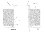
- a known fuel tank arrangement for relieving pressure differential between the interior of the aircraft fuel tank and the ambient atmosphere is shown in cross-section in Figure 1 .
- the known arrangement is denoted generally by reference numeral 1 and comprises what is often known to those skilled in the art as a stack pipe 2 located in the aircraft wing 5.
- the wing is typically a wet wing i.e. one that acts as a fuel tank.
- the stack pipe 2 is typically located in the underside of the wing 5, towards the wing tip, typically in an overflow or surge tank.
- the stack pipe 2 comprises a cylindrical main body 6, one end of which is provided with an annular flange 3, and the other end of which is provided with a burst disk 4.
- the flange 3 provides a suitable means of locating and fixing the stack pipe to the aircraft wing 5.
- fuel F may surround stack pipe 2.
- the burst disk 4 forms a burstable barrier between the interior of the fuel tank (denoted by IN) and the ambient atmosphere exterior to the fuel tank (denoted by EX).
- a threshold value typically about 8 psig for a tank overpressure and about 5 psig for a tank underpressure
- the burst disk 4 will burst, thereby permitting pressure equalisation between the interior of the fuel tank and the ambient atmosphere.
- the purpose of the burst disk 4 is to prevent an uncontrolled bursting of the wing fuel tank itself which could be dangerous.
- the burst disk will therefore burst at a pressure differential (about 8 psig for an over pressure in the tank and about 5 psig for an under pressure in the tank) which is substantially lower than the pressure differential required to burst the wing fuel tank (typically about 15 psi).
- the threshold pressure differential for bursting the disk may be different for implosion (ambient pressure greater than interior fuel tank pressure) and explosion (ambient pressure less than interior fuel tank pressure).
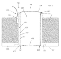
- the aircraft fuel tank arrangement is denoted generally by reference numeral 101, and comprises a removable cartridge 106 located within stack pipe 102 which is, in turn, located in the wing 105 of an aircraft.
- the stack pipe 102 is essentially the same as stack pipe 2 described above in relation to Figure 1 , having a cylindrical stack pipe main body 160 and an annular flange 103 at one end thereof.
- the stack pipe of Figs. 2 and 3 is not provided with a burst disk; the removable cartridge 106 is provided with a burst disk.
- canister 106 comprises a cylindrical cartridge main body 107 having a first burst disk 104 attached to the interior end of the cartridge main body and a second burst disk 108 attached to the exterior end of the cartridge main body.
- Air tight seals between the cartridge main body 107 and the stack pipe main body 160 are provided by three O rings, two of which 110, 111 are located towards the inner end of the cartridge and stack pipe and one of which 109 is located towards the outer end of the cartridge and stack pipe.
- the air tight seals are provided to prevent unwanted fluid pathways between the interior (IN) and exterior (EX) of the aircraft wing 105.
- Air flow paths are provided by apertures 112, 113 located in second burst disk 108. This allows air to flow into region 114 between the first and second burstable disks so that the outer surface of first burst disk 104 is subject to ambient pressure outside the aircraft.
- first and second burst disks 104, 108 remain intact. If the pressure differential between the interior of the fuel tank and the ambient atmosphere reaches or is greater than a threshold value, then first burst disk 104 will burst.
- the threshold value for burst of the first burst disk will typically be 8 psig for tank overpressure and 5 psig for tank underpressure, considerably lower than the pressure differential typically required to cause wing rupture.
- Second burst disk 108 ruptures very shortly after, and almost simultaneously with, rupture of first burst disk 104.
- the pressure differential required to rupture second burst disk 108 is typically about 3 psi, significantly lower than that required to rupture first burst disk 104.
- the apertures 112, 113 provided in second burst disk 108 are sufficiently small to prevent equalisation of pressure across second burst disk 108 by air moving through apertures 112, 113 in the event of a bursting of the first burst disk 104.
- the apertures 112, 113 also facilitate drainage of any water which accumulates in region 114.
- the second burst disk being slightly concave assists in the direction of water to apertures 112, 113.
- second burst disk 108 is substantially flush with the outer surface of flange 103 adjacent to the second burst disk 108.
- the periphery of second burst disk 108 is flush with the outer surface of the flange 103 adjacent to the periphery of the burst disk 108. This reduces drag compared to the prior art aircraft fuel tank arrangement of Figure 1 and mitigates against the establishment of resonance which could cause unwanted noise or unwanted disk burst.
- the cartridge 106 is readily removable as indicated in Figure 3 . This is to facilitate simple and inexpensive replacement of burst disks; one cartridge is removed from the stack pipe 160 and a new, substantially identical cartridge inserted into stack pipe 160.
- first burst disk 104 comprises an outer mounting rim 120 and a burstable central region 121.
- the central region 121 is typically provided with regions of weakness which permit burst of the central region when subjected to a pressure differential across the surfaces of the central region which is greater than a predetermined pressure differential. Those regions of weakness are shown as dashed lines in Fig. 4 , and form a cross shape.
- the central region 121 is provided with a continuous path 122 of conductive material. The electrical properties of the path of conductive material may be probed via wires 124, 125 which are connected to terminal block 116. Terminal block 116 is connected to a control system (not shown) by cable 115.
- the disk fails along the dashed lines shown in Fig. 4 , thereby breaking the path of conductive material 122, resulting in an open circuit.
- This open circuit may be sensed by the control system.
- the control system may be arranged to respond to the change in electrical properties in an appropriate manner. For example, it may be desirable for the aircraft to lose altitude following a disk burst.
- the control system can therefore be arranged to communicate with an aircraft control system, providing inputs to the aircraft control system commensurate with a desire to reduce aircraft altitude.
- the burst of the disk may cause an appropriate signal to be generated in the aircraft cockpit.
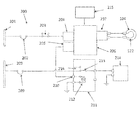
- the system which is denoted generally by reference numeral 200, controls the operation of refuel valve 214.
- the system 200 comprises a fuel management module 206 having an input 204 and a related output 205.
- the input 204 draws power from a busbar 201, subject to a refuel switch 203 being closed. In the event that the refuel switch is closed, no power is provided to the input 204.
- a burst disk monitoring module 207 is provided to interrogate the burst disk 104.
- a potential difference is provided across a continuous path 122 of conductive material.
- the fuel management module 206 is arranged so that if the burst disk 104 and continuous path 122 of conductive material are intact and the refuel switch 203 is closed, a signal is transmitted via output 205 to a relay input 210.
- the fuel management module 206 is also arranged so that if the burst disk 104 and continuous path 122 of conductive material are not intact and the refuel switch 203 is closed, a signal is not transmitted via output 205 to a relay input 210.
- relay input 210 The presence or absence of an input signal to relay input 210 causes a relay 211 to operate in a manner well known to those skilled in the art. If a signal is provided to relay input 210, electromagnet 212 operates to attract armature 213 into a position which closes switch 216, thereby providing power from busbar 208 to the refuel valve 214 via circuit breaker 209.
- the refuel valve 214 is operable so that when power is applied to the valve, the valve is open to facilitate refuelling.
- the fuel management module 206 is further in communication with cockpit flight warning module 215 so that in the event of rupture of the burst disk 104, a signal is transmitted to the cockpit flight warning module 215 which, in turn, generates a crew-recognisable warning signal which is indicative of the failure of the burst disk.
- a signal may also be sent from the fuel management module 206 to a maintenance management module (not shown) which records the failure and optionally generates a crew-recognisable or engineer-recognisable warning signal indicative of the failure of the burst disk.
- burst disks it is not necessary to have two burst disks; one will suffice. Furthermore, for certain aspects of the present invention, it is not necessary for the burst disk to be provided with electrical circuitry or optical fibres which senses for the failure of the disk. Those skilled in the art will also realise that for certain aspects of the invention, it will not be necessary to use a cartridge arrangement. Those skilled in the art will realise that for certain aspects of the invention, it is not necessary for a burst disk to be flush with the surrounding surfaces.
- burst disks described above have regions of weakness which form a cross shape. Other arrangements are possible, for example, one or more circular regions of weakness may be provided.
Landscapes
- Engineering & Computer Science (AREA)
- Aviation & Aerospace Engineering (AREA)
- Cooling, Air Intake And Gas Exhaust, And Fuel Tank Arrangements In Propulsion Units (AREA)
- Safety Valves (AREA)
Applications Claiming Priority (1)
| Application Number | Priority Date | Filing Date | Title |
|---|---|---|---|
| GB201303611A GB201303611D0 (en) | 2013-02-28 | 2013-02-28 | Aircraft fuel tank arrangement |
Publications (1)
| Publication Number | Publication Date |
|---|---|
| EP2772437A2 true EP2772437A2 (de) | 2014-09-03 |
Family
ID=48142194
Family Applications (1)
| Application Number | Title | Priority Date | Filing Date |
|---|---|---|---|
| EP20140156904 Withdrawn EP2772437A2 (de) | 2013-02-28 | 2014-02-27 | Flugzeugtreibstofftankanordnung |
Country Status (4)
| Country | Link |
|---|---|
| US (1) | US9969501B2 (de) |
| EP (1) | EP2772437A2 (de) |
| CN (1) | CN104015929A (de) |
| GB (1) | GB201303611D0 (de) |
Cited By (1)
| Publication number | Priority date | Publication date | Assignee | Title |
|---|---|---|---|---|
| JP2016147516A (ja) * | 2015-02-10 | 2016-08-18 | 三菱航空機株式会社 | バーストディスク装置および航空機 |
Families Citing this family (2)
| Publication number | Priority date | Publication date | Assignee | Title |
|---|---|---|---|---|
| GB2572553A (en) * | 2018-03-29 | 2019-10-09 | Airbus Operations Ltd | Aircraft fuel tank isolator |
| EP4400750B1 (de) * | 2023-01-10 | 2025-08-06 | Rolls-Royce plc | Hydraulische sicherung |
Family Cites Families (39)
| Publication number | Priority date | Publication date | Assignee | Title |
|---|---|---|---|---|
| GB786872A (en) | 1953-05-13 | 1957-11-27 | Graviner Manufacturing Co | Apparatus for affording rapid relief of pressure |
| US2813691A (en) * | 1954-05-03 | 1957-11-19 | Boeing Co | Automatic control for airplane fuel tank vents operable during diving |
| US3906976A (en) * | 1973-03-21 | 1975-09-23 | Sundstrand Corp | Thermally activated burst disc |
| US4301938A (en) * | 1978-08-25 | 1981-11-24 | Bs&B Safety Systems, Inc. | Safety pressure relief device |
| US4263929A (en) * | 1979-01-08 | 1981-04-28 | Kearney John G | Electropneumatic pressure relief indicator |
| US4408194A (en) * | 1981-02-02 | 1983-10-04 | Continental Disc Corporation | Capacitive pressure relief rupture disc monitor |
| US4372334A (en) * | 1981-05-18 | 1983-02-08 | Continental Disc Corporation | Overpressure relief control system |
| US4403626A (en) * | 1981-05-18 | 1983-09-13 | Continental Disc Corporation | Valve assembly |
| US4444214A (en) * | 1981-05-18 | 1984-04-24 | Continental Disc Corporation | Replaceable rupture disc cartridge arrangement |
| US4553559A (en) * | 1983-04-29 | 1985-11-19 | Bs&B Safety Systems, Inc. | Rupturable pressure relief assembly |
| US4576303A (en) | 1985-02-21 | 1986-03-18 | Bs&B Safety Systems, Inc. | Rupturable pressure relieving fluid containers |
| US4662126A (en) * | 1986-05-23 | 1987-05-05 | Fike Corporation | Vibration resistant explosion control vent |
| US4978947A (en) * | 1989-05-25 | 1990-12-18 | Bs&B Safety Systems, Inc. | Rupturable fluid flow indicator |
| US5050630A (en) * | 1990-12-03 | 1991-09-24 | Bs&B Safety Systems, Inc. | Self-positioning rupture disk assembly |
| US5082133A (en) * | 1991-08-01 | 1992-01-21 | Bs&B Safety Systems, Inc. | Low pressure rupture disk and assembly |
| US5121847A (en) * | 1992-01-22 | 1992-06-16 | Bs&B Safety Systems, Inc. | Carbon rupture disk element and assembly |
| US5583490A (en) * | 1994-07-15 | 1996-12-10 | Htv Industries, Inc. | Rupture disk monitoring apparatus |
| US5934308A (en) * | 1995-10-24 | 1999-08-10 | Bs&B Safety Systems, Inc. | Rupture disk apparatus and methods |
| US5913807A (en) * | 1998-03-30 | 1999-06-22 | Williams International Corp. L.L.C. | Turbojet engine start system |
| EP1181473B1 (de) * | 1999-05-13 | 2006-08-09 | BS & B Safety Systems Limited | Berstscheibenanordnung |
| US6178983B1 (en) * | 1999-05-13 | 2001-01-30 | Bs&B Safety Systems, Inc. | Rupture disk assembly |
| US6230733B1 (en) * | 2000-01-20 | 2001-05-15 | Oklahoma Safety Equipment Co. | Self-contained rupture disk cartridge |
| US6311715B1 (en) * | 2000-07-07 | 2001-11-06 | Zook Enterprises, Llc | Stacked rupture disk assembly |
| BR8301655Y1 (pt) | 2003-03-12 | 2013-12-24 | Dias Miguel Greyde Avila | Válvula magnética recuperadora de vapores e gases |
| GB0619443D0 (en) * | 2006-10-02 | 2006-11-08 | Airbus Uk Ltd | A valve |
| GB0625670D0 (en) * | 2006-12-21 | 2007-01-31 | Airbus Uk Ltd | Overpressure protector |
| GB0710269D0 (en) * | 2007-05-30 | 2007-07-11 | Airbus Uk Ltd | Overpressure protection for an aircraft fuel tank system |
| US8002142B2 (en) * | 2008-06-19 | 2011-08-23 | Honeywell International Inc. | Ambient pressure-responsive variable volume fuel tank |
| IT1397291B1 (it) * | 2009-12-10 | 2013-01-04 | Eltek Spa | Dispositivo di rilevazione. |
| CN101891017B (zh) | 2010-07-20 | 2013-04-10 | 中国航空工业集团公司西安飞机设计研究所 | 一种燃油箱惰化控制装置 |
| GB201012723D0 (en) * | 2010-07-29 | 2010-09-15 | Airbus Operations Ltd | Improvements relating to venting gas from a tank |
| DE102011011976B4 (de) | 2011-02-22 | 2013-11-14 | Airbus Operations Gmbh | Dekompressionsanordnung für ein Luftfahrzeug |
| GB201107087D0 (en) * | 2011-04-28 | 2011-06-08 | Airbus Operations Ltd | A flame trap cartridge, flame arrestor, method of preventing flame propagation into a fuel tank and method of operating an aircraft |
| EP2550994B1 (de) | 2011-07-25 | 2014-07-02 | Intertechnique | Regelventil für ein Lebenserhaltungssystem |
| CN202209321U (zh) | 2011-08-18 | 2012-05-02 | 重庆耐德燃气设备有限公司 | 一种液压子站用油箱 |
| FR2981880B1 (fr) * | 2011-10-28 | 2014-09-19 | Daher Aerospace | Procede pour etancher un reservoir de carburant |
| GB201202545D0 (en) * | 2012-02-14 | 2012-03-28 | Airbus Uk Ltd | Aircraft fuel tank vent protector |
| EP2664547B1 (de) * | 2012-05-16 | 2016-04-06 | Airbus Operations, S.L. | Abdeckung für äußeren Kraftstofftankzugang, Flügel und Flugzeug |
| JP6674740B2 (ja) * | 2015-02-10 | 2020-04-01 | 三菱航空機株式会社 | バーストディスク装置および航空機 |
-
2013
- 2013-02-28 GB GB201303611A patent/GB201303611D0/en not_active Ceased
-
2014
- 2014-02-27 EP EP20140156904 patent/EP2772437A2/de not_active Withdrawn
- 2014-02-28 CN CN201410073825.6A patent/CN104015929A/zh active Pending
- 2014-02-28 US US14/194,596 patent/US9969501B2/en active Active
Cited By (1)
| Publication number | Priority date | Publication date | Assignee | Title |
|---|---|---|---|---|
| JP2016147516A (ja) * | 2015-02-10 | 2016-08-18 | 三菱航空機株式会社 | バーストディスク装置および航空機 |
Also Published As
| Publication number | Publication date |
|---|---|
| US9969501B2 (en) | 2018-05-15 |
| CN104015929A (zh) | 2014-09-03 |
| GB201303611D0 (en) | 2013-04-17 |
| US20150122948A1 (en) | 2015-05-07 |
Similar Documents
| Publication | Publication Date | Title |
|---|---|---|
| US9969501B2 (en) | Aircraft fuel tank arrangement | |
| EP2882010B1 (de) | Batteriefachbelüftungssystem | |
| EP3306705A2 (de) | Druckreliefmechanismus und gehäuse | |
| US8109470B2 (en) | Overpressure protector | |
| US4237935A (en) | Hydraulic pressure relief valve and fluid isolator | |
| CN104051754B (zh) | 热压力释放设备和相关的系统和方法 | |
| US10209153B2 (en) | Pressure indicating device | |
| US10041849B2 (en) | System for detecting a pressure difference between the interior and the exterior of an aircraft | |
| US8428793B2 (en) | Automatic downlink messaging during emergency flight situations | |
| US11539261B2 (en) | Breather device | |
| CN106774476A (zh) | 一种飞机油箱油面控制系统 | |
| US2910080A (en) | Impact responsive valve | |
| US8496021B2 (en) | Overpressure valve for an aircraft | |
| US20110056974A1 (en) | Aircraft fuel tank system | |
| EP3112191A1 (de) | Reifendrucksensoranordnungen mit einem reifendrucksensor zur anpassung an ein überdruckentlastungsventil in einem flugzeugradsystem | |
| US9285045B2 (en) | Aircraft fuel tank vent protector | |
| US20210293351A1 (en) | Tank level sensor | |
| US20260077877A1 (en) | Airplane fuel contaminant detection system | |
| US20240063500A1 (en) | Degassing unit with segmented membrane | |
| EP3034917A1 (de) | Kombination aus reifendrucksensor und druckentlastungsventil gegen übermässiges aufpumpen | |
| WO2014204582A1 (en) | Retrievable sensor and method | |
| US20240391606A1 (en) | Fuel tank monitoring system | |
| KR20180071547A (ko) | 수소공급밸브와 수소차단밸브 사이의 파단부를 포함하는 연료전지 시스템 | |
| CN212313889U (zh) | 一种基于波音飞机挡风玻璃脱落情况下的应急供氧装置 | |
| US11136106B2 (en) | System for detecting an overpressure in the interior of an aircraft |
Legal Events
| Date | Code | Title | Description |
|---|---|---|---|
| PUAI | Public reference made under article 153(3) epc to a published international application that has entered the european phase |
Free format text: ORIGINAL CODE: 0009012 |
|
| 17P | Request for examination filed |
Effective date: 20140227 |
|
| AK | Designated contracting states |
Kind code of ref document: A2 Designated state(s): AL AT BE BG CH CY CZ DE DK EE ES FI FR GB GR HR HU IE IS IT LI LT LU LV MC MK MT NL NO PL PT RO RS SE SI SK SM TR |
|
| AX | Request for extension of the european patent |
Extension state: BA ME |
|
| STAA | Information on the status of an ep patent application or granted ep patent |
Free format text: STATUS: THE APPLICATION HAS BEEN WITHDRAWN |
|
| 18W | Application withdrawn |
Effective date: 20170217 |