EP2772418A2 - Means to widen a transport device, and transport device - Google Patents
Means to widen a transport device, and transport device Download PDFInfo
- Publication number
- EP2772418A2 EP2772418A2 EP14000718.8A EP14000718A EP2772418A2 EP 2772418 A2 EP2772418 A2 EP 2772418A2 EP 14000718 A EP14000718 A EP 14000718A EP 2772418 A2 EP2772418 A2 EP 2772418A2
- Authority
- EP
- European Patent Office
- Prior art keywords
- carrier
- arms
- support
- transport
- support elements
- Prior art date
- Legal status (The legal status is an assumption and is not a legal conclusion. Google has not performed a legal analysis and makes no representation as to the accuracy of the status listed.)
- Granted
Links
Images


Classifications
-
- B—PERFORMING OPERATIONS; TRANSPORTING
- B62—LAND VEHICLES FOR TRAVELLING OTHERWISE THAN ON RAILS
- B62D—MOTOR VEHICLES; TRAILERS
- B62D33/00—Superstructures for load-carrying vehicles
- B62D33/02—Platforms; Open load compartments
-
- B—PERFORMING OPERATIONS; TRANSPORTING
- B62—LAND VEHICLES FOR TRAVELLING OTHERWISE THAN ON RAILS
- B62D—MOTOR VEHICLES; TRAILERS
- B62D21/00—Understructures, i.e. chassis frame on which a vehicle body may be mounted
- B62D21/09—Means for mounting load bearing surfaces
-
- B—PERFORMING OPERATIONS; TRANSPORTING
- B62—LAND VEHICLES FOR TRAVELLING OTHERWISE THAN ON RAILS
- B62D—MOTOR VEHICLES; TRAILERS
- B62D21/00—Understructures, i.e. chassis frame on which a vehicle body may be mounted
- B62D21/14—Understructures, i.e. chassis frame on which a vehicle body may be mounted of adjustable length or width
-
- B—PERFORMING OPERATIONS; TRANSPORTING
- B62—LAND VEHICLES FOR TRAVELLING OTHERWISE THAN ON RAILS
- B62D—MOTOR VEHICLES; TRAILERS
- B62D21/00—Understructures, i.e. chassis frame on which a vehicle body may be mounted
- B62D21/18—Understructures, i.e. chassis frame on which a vehicle body may be mounted characterised by the vehicle type and not provided for in groups B62D21/02 - B62D21/17
- B62D21/20—Understructures, i.e. chassis frame on which a vehicle body may be mounted characterised by the vehicle type and not provided for in groups B62D21/02 - B62D21/17 trailer type, i.e. a frame specifically constructed for use in a non-powered vehicle
-
- B—PERFORMING OPERATIONS; TRANSPORTING
- B62—LAND VEHICLES FOR TRAVELLING OTHERWISE THAN ON RAILS
- B62D—MOTOR VEHICLES; TRAILERS
- B62D33/00—Superstructures for load-carrying vehicles
- B62D33/08—Superstructures for load-carrying vehicles comprising adjustable means
-
- B—PERFORMING OPERATIONS; TRANSPORTING
- B62—LAND VEHICLES FOR TRAVELLING OTHERWISE THAN ON RAILS
- B62D—MOTOR VEHICLES; TRAILERS
- B62D53/00—Tractor-trailer combinations; Road trains
- B62D53/04—Tractor-trailer combinations; Road trains comprising a vehicle carrying an essential part of the other vehicle's load by having supporting means for the front or rear part of the other vehicle
- B62D53/06—Semi-trailers
- B62D53/067—Multi-purpose, convertible or extendable load surface semi-trailers
-
- B—PERFORMING OPERATIONS; TRANSPORTING
- B62—LAND VEHICLES FOR TRAVELLING OTHERWISE THAN ON RAILS
- B62D—MOTOR VEHICLES; TRAILERS
- B62D63/00—Motor vehicles or trailers not otherwise provided for
- B62D63/06—Trailers
- B62D63/061—Foldable, extensible or yielding trailers
Definitions
- the invention relates to means for broadening a means of transport, as well as a means of transport.
- the means of transport is in particular a so-called excavator bridge, which i.a. can be used for transporting heavy construction machines with excess width and whose loading platform must be widened.
- excavator bridges are heavy-duty transport means in the form of a low-lying, telescopic or non-telescoping bridge girder with a loading platform referred to at its front and at its rear end over a have appropriate coupling by means of which they can be engaged in a suitable, front, at least single-axle vehicle, or a gooseneck and a suitable, rear, at least single-axle vehicle.
- the longitudinal or main girder is at least in two parts and comprises an outer girder, in the form of an outer telescope and at least one inner girder telescoping in relation to the outer girder in the direction of travel of the means of transport, in the form of an inner telescope which can be locked in different telescoping positions.
- a transport of loads with an over-width of more than 2550 mm is possible, such as Transport of wide crawler excavators, means are already known for widening the loading platform of the excavator bridge, which can be mounted or mounted as needed on the two opposite sides of the longitudinal or main beam to provide additional load bearing surfaces on both sides of the longitudinal or main beam.
- the means for widening the excavator bridge consist of hinged arms on the tops of the support elements are placed and fixed so that they each on both sides of the longitudinal or main carrier in the longitudinal direction of the excavator bridge, form a level load bearing surface.
- the removable jibs have a cranked shape and are mountable in two mounting orientations on the carrier. In a first mounting orientation in which the crank is facing up, the tops of the support members placed on the arms span a plane with the top of the longitudinal or main beam, as in FIG Fig. 12 shown on the right. In a second, rotated by 180 degrees mounting orientation of the boom, in which the bend points down, have the tops of the support elements lying on the arms on a lower height, as in Fig. 12 shown on the left.
- the loading height of the support elements can be reduced and thus the usable transport height can be increased, provided that the load can be parked exclusively on both sides of the longitudinal or main support on the support elements.
- the offset of the outriggers is on the in Fig. 12 limited extent shown, as a stronger cranking of the boom would cause either in the first mounting orientation of the boom, the support members up over the top of the longitudinal or main beam or in the second mounting orientation of the boom whose undersides down over the bottom of the longitudinal - or Haupttexs would survive, both of which is undesirable.
- the second mounting orientation of the boom further lowered the load bearing surface and thereby the maximum loading height of the load can be further increased.
- the clear height of the undersides can be increased above the ground, as then, for example, when driving through a tight curve, the boom on the inside of the curve better on a roadway boundary, such as a guardrail, can move away.
- the support elements consist in the known means of transport of the type mentioned either from a flat box made by welding thin steel sheet or welded hollow sections, on the O-side wooden pads are screwed. In both cases, the weight of the supporting elements is between 500 and 700 N, which makes the upgrade of the excavator bridge when widening the loading platform as well as the disassembly during dismantling considerably more difficult.
- a means for widening a means of transport comprising a plurality of cranked arms which are mounted on opposite sides of a support of the transport means at a distance from each other so that they protrude laterally beyond the carrier, and with a plurality of excavating elements, each between let use adjacent brackets known.
- the present invention seeks to improve means for widening a means of transport of the type mentioned, in particular a excavator bridge, and a means of transport of the type mentioned in that in the second mounting orientation of the cranked boom, the maximum loading height of the load or in the first mounting orientation of the boom can increase the clear height of the undersides above the ground.
- a further object of the invention is to facilitate the handling of the support elements.
- the first-mentioned task namely the increase in the maximum loading height in the second mounting orientation of the boom or the increase in the clear height of the lower sides of the boom in the first mounting orientation, according to a first variant of the invention achieved in that the boom an I-profile with two On both sides of a central web arranged, open to opposite sides open channel-shaped recesses, so that let the support elements individually with their opposite ends from the outside into the opposite recesses of two adjacent arms.
- a preferred development of the first variant of the invention provides that the arms are integrally formed and connectable to the carrier, ie the longitudinal or main carrier of the transport in two different mounting orientations, in which the upper sides of the inserted into the recesses support elements have different heights.
- the support elements are placed on the upper sides thereof neither in the first nor in the second mounting orientation of the boom but are inserted between adjacent arms, by the above feature combination on the one hand in the second mounting orientation of the boom, in comparison to the Fig. 12 illustrated prior art, the top of the support elements are moved to the height down.
- the maximum loading height can be increased by the height of the support elements, without the height dimensions of the boom reduced and thus their capacity is impaired.
- the crank of the boom can be somewhat reinforced, which in the first mounting orientation of the boom, the clear height between the bottom and the ground can be increased.
- the cranked arms comprise a straight receiving part provided with the channel-shaped recesses, which accommodates the ends of two adjacent support elements, a fastening part which can be detachably connected to the carrier of the transport means in both mounting orientations of the arm, and a supporting part arranged therebetween, via which the Receiving part supported against the carrier, wherein the support member is suitably rigidly connected to the receiving part and the fixing part and inclined to achieve the offset in relation to the receiving part.
- the straight receiving part is always formed as an I-profile to allow the insertion of the support elements between the two receiving parts of the adjacent boom of the support member does not necessarily have an I-profile, since it does not serve to insert the support elements. Because, however I-profiles in the direction of the central web have a high rigidity, the inclined support member is expediently also formed as an I-profile.
- the carrier of the means of transport is a telescoping carrier with an inner and outer carrier
- the two brackets for attaching the boom according to another preferred embodiment of the invention are formed both on the inner and outer carrier, so that the boom in the form-fitting both be connected to the inner and outer carrier.
- the fastening part in both mounting orientations can be detachably connected to the carrier of the transport means, it advantageously has an upwardly projecting and a downwardly protruding projection, which is received in an upper or a lower holder of the carrier when connecting the arm to the carrier ,
- the two projections are preferably shaped so that they can be inserted without the need of other moving parts in the associated support by the boom is approximated in an inclined orientation of the fastening part to the support in order to first in this orientation the upstanding projection from below, insert as far as possible into the upper support by then pivoting the cantilever to move the downwardly projecting projection over the lower support, and finally lowering the cantilever a bit until the downwardly projecting projection is downwards protrudes into the lower bracket and the boom is supported on the lower bracket. In this state, the protruding upward projection still engages behind the abutment of the upper bracket.
- the upper bracket serves to receive the upper bearing force resulting from the load moment acting on the boom.
- the lower bracket is suitably designed so that the bracket rests on the lower bracket after mounting, is supported from above against the lower bracket and the lower projection protrudes from above into the lower bracket, while the upper bracket is formed so that the upper projection engages behind a stable abutment on its side facing away from the carrier in order to introduce the load moments acting on the boom in the carrier.
- the two projections are mirror-symmetrical to a vertical center of the support and / or attachment part, so that they can be brought in both mounting orientations in the same manner with the brackets in engagement.
- the positive connection between the boom and the carrier is preferably achieved in that the two projections and the holders serving to receive the projections each have a non-circular complementary cross-section.
- the inserted into the recesses support elements can be fixed in at least two and better still at three different distances from the main carrier.
- fixing means comprise two openings at the opposite ends of the support elements, at least two at different distances from the carrier in the central web of each boom through openings and a plurality of fixing bolts, which in each case by two openings of adjacent support members and by a with leave this aligned passage opening of the central web of a boom located between the support elements through.
- the further object namely to facilitate the handling of the support elements, according to a second variant of the invention and preferred development the first variant of the invention achieved in that the support elements are made in lightweight construction of light metal or a fiber-reinforced plastic.
- these are preferably made in a sandwich construction and comprise a layer of a foamed material between at least two outer layers.
- the support elements can be made of either light metal or plastic, in the former case, the foamed material is a light metal foam and the cover layers are light metal plates, while in the latter case, the foamed material is a hard foam, while the cover layers are made of a fiber-reinforced plastic, expediently reinforced by glass fibers, carbon fibers or Kevlar fibers plastic.
- the foamed material is preferably surrounded by a frame which is rigidly connected to both cover layers.
- the support elements for further weight reduction is expediently smaller than the height of the recesses of the boom, are preferably attached to the undersides of the two opposite ends of the support elements downwardly projecting strips or projections whose height is slightly smaller than the difference between the height of Recesses of the boom and the height of the support elements. This prevents a height difference between the outer sides of the support elements and the upper sides of the outriggers.
- the transport means 20 is a so-called excavator bridge, i. a serving for receiving the load low-lying loading platform 22, the width of which can be adapted to the width of the load.
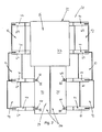
- FIGS. 1 and 2 shown which show a portion of the drop-bed loading platform 22, this latter consists mainly of an elongated, in the illustrated case simply telescopically running longitudinal or main beam 24 which has at its front and at its rear end via a corresponding coupling, by means of which he in a suitable, front, at least single-axle vehicle, or a gooseneck and a suitable, rear, at least uniaxial vehicle can be engaged.
- the loading platform 22 can be widened if necessary, by on both sides the longitudinal or main beam 24 in the longitudinal direction of the transport means 20 equidistantly from each other a plurality of laterally projecting arms 40 is attached, of which only a few are shown in the drawing, and between the adjacent boom 40 support members 42 are used, which the gaps between the arms 40 bridge.
- the planar top of the longitudinal or main beam 24 serves as a load bearing surface onto which a load, e.g. a crawler excavator, can be placed directly.
- brackets 44, 46 For mounting the boom 40 of the longitudinal or main beam 24 is provided on the two opposite outer side walls 36 of the two box girder 30 and the double box girder 26 each with paired superimposed brackets 44, 46.
- the upper holder 44 comprises a bracket 50 made of a piece of flat steel with an angular U-shaped outline, which in the illustrated case of a telescopic excavator bridge is welded from underneath to the protruding edge of upper cover plates 32 of the two box girders 30 the yoke of the bracket 50 facing away from the carrier 24 to the outside.
- the bracket 50 surrounds a rectangular in cross-section receiving opening 52.
- the edge of the upper cover plate 33 of the outer double-box girder 26 at the bottom be reinforced by an L-profile 54, which is provided in the region of the upper bracket 44, with a recess into which the bracket 50 is welded.
- the upper cover plate 32 of the two box girder 30 is provided above the receiving opening 52 of each holder 44 with a recess 55.
- the lower bracket 46 also includes a bracket 56 which is slightly higher than the bracket 50 of the upper bracket 44 and in a reverse orientation as the upper bracket 50 on the O-side of a lower cover plate 34 (in Fig. 8 not shown) of the two box girder 30 of the longitudinal or main beam 24 is welded, so that the yoke of the bracket 56 points in the direction of the adjacent box girder 30.
- the two legs of the bracket 56 are connected in the vicinity of the underside of the bracket 56 by a flat web 58, which surrounds a rectangular cross-section receiving opening 60 together with the bracket 56.
- the edge of a lower cover plate of the outer double-box girder 26 may be reinforced at the top by an L-profile 62 which is provided in the region of the lower support 46 with a recess into which the bracket 56 is welded.
- the brackets 40 are integrally formed and essentially consist of a straight receiving part 64 for receiving the facing ends of two adjacent support elements 42, a fastening part 66 for fastening the brackets 40 to two superimposed brackets 44 and 46 of the longitudinal or main beam 24 and a support member 68 disposed between the receiving member 64 and the mounting member 66.
- the support members 68 hold the receiving members 64 in alignment parallel to the substrate and cover plate 26 and guide the support members 42 to the female members 64 Loads in the brackets 44 and 46 and thus in the longitudinal or main carrier 24 a.
- the straight receiving portion 64 of each arm 40 is formed as an I-profile with a generally constant mirror-symmetrical cross-section.
- the I-profile consists of a vertical central web 70, a welded to an edge of the central web, perpendicular to the central web first crosspiece 72 and welded to the other edge of the central web, parallel to the first transverse web 72 second transverse web 74.
- the central web 70 and the two Transverse webs 72, 74 define on both sides of the central web 70 a channel-shaped recess 76 which is open away from the central web 70 and has a generally constant rectangular cross-section.
- In the vicinity of the support member 68 of the central web 70 is provided with three spaced-apart through holes 78.
- each arm 40 is also formed as an I-profile, the central web 80 and transverse webs 82, 84 are arranged in extension of the central web 70 and the corresponding transverse web 72, 74 of the receiving part 64, but wherein the height of the central web 80 from the receiving part 64 increases to the fastening part 66 and wherein the two transverse webs 82, 84 are bent with different degrees of inclination in the direction of the fastening part 66 out.
- the boom 40 has a cranked shape, while the cross section of the support member 68 increases in the direction of the fastening part 66.
- stiffening plates 86 are welded on both sides of the Mitteilstegs 70, 80 in the corner between this and the more inclined or stronger bent crossbar 84.
- the fastening part 66 consists essentially of a fastening pin 88 with a rectangular cross-section, which is aligned parallel to the central web 70, 80 and extends along the end remote from the receiving part 64 of the support member 68, wherein it passes through the two transverse webs 82, 84, so that its opposite ends 90, 92 respectively a piece far up or down over the adjacent cross bar 82, 84 survive.
- the mounting pin 88 is welded over the entire height of the central web 80 and in the region of the transverse webs 82, 84 with the support member 68. Between the two transverse webs 82, 84 stiffening plates 94 are welded into the corners between each transverse web 82, 84 and the adjacent, parallel to the central web 80 sides of the mounting pin 88.
- the two projecting ends 90, 92 are mirror-symmetrical to the center of the mounting pin 88 and are provided with a flat bevel 96 between their flat, perpendicular to the longitudinal axis of the mounting pin 88 end faces and their side facing away from the receiving part 64 sides.
- each bracket 40 can be mounted in two different mounting orientations on the longitudinal or main beam 24, as in FIG 3 and 4 or 11 shown.
- the receiving parts 64 of the arms 40 are aligned parallel to the ground and the upper cover plates 32, 33, wherein in a first mounting orientation their tops are approximately aligned with the tops of the upper cover plates 32, 33 of the longitudinal or main beam 24, as in Fig. 3 and Fig. 11 shown on the right, while in a second mounting orientation their bottoms are approximately aligned with the underside of the longitudinal or main beam 24, as in Fig. 4 and Fig. 11 shown on the left.
- the tops of the support members 42 and the receiving portions 64 of the beams 40 on each side of the longitudinal or main beam 24 form a continuous load bearing surface.
- the load bearing surface can be arranged at different distances from the longitudinal or main carrier 24 by the support elements 42 are more or less inserted into the recesses 76 of the receiving parts 64 of the boom 40, as in Fig. 1 and 2 shown.
- the two protruding ends 90, 92 of the mounting pins 88 are each in an upper and a lower bracket 44th or 46 introduced on the longitudinal or main carrier 24.
- the mounting pin 88 is approximated to the longitudinal or main beam 24 in an inclined orientation, in which the upper end 90 and 92, the longitudinal or main beam 24 is closer. In this orientation, then the protruding upper end 90 and 92 of the mounting pin 88 is inserted from below into the receiving opening 52 of the upper bracket 44 until the upper cross bar 82 of the support member 68 abuts against the lower edge of the bracket 50 from below.
- the entire boom 40 is slightly pivoted to move the downwardly projecting end 92 and 90 of the mounting pin 88 over the web 58 across the receiving opening 60 of the lower bracket 46.
- the boom 40 is slightly lowered in vertical alignment of the mounting pin 88 until the end 92 and 90 of the mounting pin 88 projects from above into the receiving opening 60 and the lower cross bar 82 and 84 of the support member 66 on the flat top of the bracket 56th supported. In this condition, the boom 40 can not move out of the brackets 44, 46 by itself.
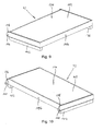
- the support members 42 consist of a flat cuboid support member 100 and two strips 102 which are secured to the opposite ends of the support member 100 on its underside.
- the support member 100 consists of a sandwich construction comprising an upper and a lower cover plate 104 made of aluminum sheet or a fiber composite material, an interposed layer of aluminum foam or rigid foam (not visible), and a surrounding the sandwich construction frame 106 made of aluminum sheet or a Fiber composite material comprises.
- the two arranged at the ends of the support member 100 parts of the frame 106 have projecting ends 108 which are formed as eyes with a bore 110 and serve to fix the support member 42 in the adjacent arms 40.
- the support members 42 are each inserted from the outside between two adjacent boom 40, such as in the FIGS. 1 . 3 and 4 shown.
- the two opposite ends of each support member 42 are inserted into two opposite channel-shaped recesses 76 of two adjacent arms 40.
- the two strips 102 are on the downwardly facing transverse webs 72 and 74 of the receiving part 64, while the upwardly facing transverse webs 74 and 72, the tops of the support members 42 overlap at their ends, so that the Load bearing surface there is a few millimeters higher than in the region of the support elements 42.
- All support members 42 are inserted so far into the recesses of adjacent boom 40 until they have one of three possible distances from the longitudinal or main beam 24/26, in which the holes 110 of the two protruding ends 108 of the frontal parts of the frame 106 of all support members 42nd aligned with one of the three passage openings 78 in the central web 70 of the respective adjacent boom 40.
- fixing bolts 112 are pushed and secured from one side through a bore 110 of a support element 42, the adjacent passage opening 78 and an adjacent bore 110 of the next support element 42 in order to fix the support elements 42 in the desired position.
Abstract
Description
Die Erfindung betrifft Mittel zur Verbreiterung eines Transportmittels, sowie ein Transportmittel. Bei dem Transportmittel handelt es sich insbesondere um eine so genannte Baggerbrücke, die u.a. zum Transport von schweren Baumaschinen mit Überbreite eingesetzt werden kann und deren Ladeplattform dazu verbreitert werden muss.The invention relates to means for broadening a means of transport, as well as a means of transport. The means of transport is in particular a so-called excavator bridge, which i.a. can be used for transporting heavy construction machines with excess width and whose loading platform must be widened.
Als Baggerbrücken werden Schwerlast-Transportmittel in Form eines tiefliegenden, teleskopierbaren oder nicht teleskopierbaren Brückenträgers mit einer Ladeplattform bezeichnet, die an ihrem vorderen und an ihrem hinteren Ende über eine entsprechende Kupplung verfügen, mittels derer sie in ein geeignetes, vorderes, mindestens einachsiges Fahrzeug, oder einen Schwanenhals und ein geeignetes, hinteres, mindestens einachsiges Fahrzeug eingekuppelt werden können.As excavator bridges are heavy-duty transport means in the form of a low-lying, telescopic or non-telescoping bridge girder with a loading platform referred to at its front and at its rear end over a have appropriate coupling by means of which they can be engaged in a suitable, front, at least single-axle vehicle, or a gooseneck and a suitable, rear, at least single-axle vehicle.
Bei teleskopierbaren Baggerbrücken ist der Längs- oder Hauptträger mindestens zweiteilig ausgebildet und umfasst einen Außenträger, in Form eines Außenteleskops und mindestens einen in Bezug zum Außenträger in Fahrtrichtung des Transportmittels teleskopierbaren Innenträger, in Form eines Innenteleskops, der sich in unterschiedlichen Teleskopierstellungen arretieren lässt.In the case of telescopic excavator bridges, the longitudinal or main girder is at least in two parts and comprises an outer girder, in the form of an outer telescope and at least one inner girder telescoping in relation to the outer girder in the direction of travel of the means of transport, in the form of an inner telescope which can be locked in different telescoping positions.
Um sicherzustellen, dass einerseits bei Leerfahrten oder beim Transport von Lasten mit einer Breite von weniger als 2550 mm keine Sondergenehmigung für die Baggerbrücke benötigt wird, andererseits aber auch ein Transport von Lasten mit einer Überbreite von mehr als 2550 mm, möglich ist, wie zum Beispiel ein Transport von breiten Raupenbaggern, sind bereits Mittel zur Verbreiterung der Ladeplattform der Baggerbrücke bekannt, die bei Bedarf an den zwei entgegengesetzten Seiten des Längs- oder Hauptträgers angebracht oder montiert werden können, um beiderseits des Längs- oder Hauptträgers eine zusätzliche Lastauflageflächen zu schaffen.To ensure that no special permit for the excavator bridge is needed for empty runs or for the transport of loads with a width of less than 2550 mm, on the other hand, a transport of loads with an over-width of more than 2550 mm is possible, such as Transport of wide crawler excavators, means are already known for widening the loading platform of the excavator bridge, which can be mounted or mounted as needed on the two opposite sides of the longitudinal or main beam to provide additional load bearing surfaces on both sides of the longitudinal or main beam.
Bei einigen bekannten Transportmitteln der eingangs genannten Art in Form einer Baggerbrücke bestehen die Mittel zur Verbreiterung der Baggerbrücke aus klappbaren Auslegern, auf deren Oberseiten die Tragelemente aufgelegt und fixiert werden, so dass sie jeweils beiderseits des Längs- oder Hauptträgers eine in Längsrichtung der Baggerbrücke durchgehende, ebene Lastauflagefläche bilden. Die abnehmbaren Ausleger besitzen eine gekröpfte Form und sind in zwei Montageausrichtungen am Träger montierbar. In einer ersten Montageausrichtung, in der die Kröpfung nach oben weist, spannen die Oberseiten der auf die Ausleger aufgelegten Tragelemente mit der Oberseite des Längs- oder Hauptträgers eine Ebene auf, wie in
Dadurch kann im Vergleich zur ersten Montageausrichtung die Ladehöhe der Tragelemente verkleinert und somit die nutzbare Transporthöhe vergrößert werden, sofern die Last ausschließlich beiderseits des Längs- oder Hauptträgers auf den Tragelementen abgestellt werden kann. Die Kröpfung der Ausleger ist auf das in
Um beim Durchfahren von Unterführungen oder Brücken die Höhe des Transportmittels einschließlich der Last so niedrig wie möglich zu halten, ist es von Vorteil, wenn in der zweiten Montageausrichtung der Ausleger die Lastauflagefläche weiter abgesenkt und dadurch die maximale Ladehöhe der Last weiter vergrößert werden kann. Außerdem ist es auch von Vorteil, wenn in der ersten Montageausrichtung der Ausleger die lichte Höhe von deren Unterseiten über dem Untergrund vergrößert werden kann, da sich dann zum Beispiel beim Durchfahren einer engen Kurve die Ausleger an der Kurveninnenseite besser über eine Fahrbahnbegrenzung, wie zum Beispiel eine Leitplanke, hinweg bewegen können.In order to keep the height of the means of transport including the load as low as possible when driving through underpasses or bridges, it is advantageous if in the second mounting orientation of the boom further lowered the load bearing surface and thereby the maximum loading height of the load can be further increased. Moreover, it is also advantageous if in the first mounting orientation of the boom, the clear height of the undersides can be increased above the ground, as then, for example, when driving through a tight curve, the boom on the inside of the curve better on a roadway boundary, such as a guardrail, can move away.
Die Tragelemente bestehen bei den bekannten Transportmitteln der eingangs genannten Art entweder aus einem durch Schweißen aus dünnem Stahlblech hergestellten flachen Kasten oder aus verschweißten Hohlprofilen, auf deren O-berseiten hölzerne Auflagen aufgeschraubt sind. In beiden Fällen beträgt das Gewicht der Tragelemente zwischen 500 und 700 N, wodurch das Aufrüsten der Baggerbrücke beim Verbreitern der Ladeplattform sowie das Abrüsten beim Rückbau erheblich erschwert werden.The support elements consist in the known means of transport of the type mentioned either from a flat box made by welding thin steel sheet or welded hollow sections, on the O-side wooden pads are screwed. In both cases, the weight of the supporting elements is between 500 and 700 N, which makes the upgrade of the excavator bridge when widening the loading platform as well as the disassembly during dismantling considerably more difficult.
Aus der
Ausgehend hiervon liegt der Erfindung die Aufgabe zugrunde, Mittel zur Verbreiterung eines Transportmittels der eingangs genannten Art, insbesondere einer Baggerbrücke, sowie ein Transportmittel der eingangs genannten Art dahingehend zu verbessern, dass sich in der zweiten Montageausrichtung der gekröpften Ausleger die maximale Ladehöhe der Last bzw. in der ersten Montageausrichtung der Ausleger die lichte Höhe von deren Unterseiten über dem Untergrund vergrößern lässt. Außerdem besteht eine weitere Aufgabe der Erfindung darin, die Handhabung der Tragelemente zu erleichtern.Based on this, the present invention seeks to improve means for widening a means of transport of the type mentioned, in particular a excavator bridge, and a means of transport of the type mentioned in that in the second mounting orientation of the cranked boom, the maximum loading height of the load or in the first mounting orientation of the boom can increase the clear height of the undersides above the ground. In addition, a further object of the invention is to facilitate the handling of the support elements.
Die zuerst genannte Aufgabe, nämlich die Vergrößerung der maximalen Ladehöhe in der zweiten Montageausrichtung der Ausleger bzw. die Vergrößerung der lichten Höhe der Unterseiten der Ausleger in der ersten Montageausrichtung, wird gemäß einer ersten Erfindungsvariante dadurch gelöst, dass die Ausleger ein I-Profil mit zwei beiderseits von einem Mittelsteg angeordneten, nach entgegengesetzten Seiten offenen rinnenförmigen Ausnehmungen umfassen, so dass sich die Tragelemente einzeln mit ihren entgegengesetzten Enden von außen her in die gegenüberliegenden Ausnehmungen zweier benachbarter Ausleger einschieben lassen.The first-mentioned task, namely the increase in the maximum loading height in the second mounting orientation of the boom or the increase in the clear height of the lower sides of the boom in the first mounting orientation, according to a first variant of the invention achieved in that the boom an I-profile with two On both sides of a central web arranged, open to opposite sides open channel-shaped recesses, so that let the support elements individually with their opposite ends from the outside into the opposite recesses of two adjacent arms.
Eine bevorzugte Weiterbildung der ersten Erfindungsvariante sieht vor, dass die Ausleger einstückig ausgebildet und mit dem Träger, d.h. dem Längs- oder Hauptträger des Transportmittels in zwei verschiedenen Montageausrichtungen verbindbar sind, in denen die Oberseiten der in die Ausnehmungen eingeschobenen Tragelemente unterschiedliche Höhen aufweisen.A preferred development of the first variant of the invention provides that the arms are integrally formed and connectable to the carrier, ie the longitudinal or main carrier of the transport in two different mounting orientations, in which the upper sides of the inserted into the recesses support elements have different heights.
Da die Tragelemente weder in der ersten noch in der zweiten Montageausrichtung der Ausleger auf deren Oberseiten aufgelegt sondern zwischen benachbarte Ausleger eingeschoben werden, kann durch die obige Merkmalskombination zum einen in der zweiten Montageausrichtung der Ausleger, im Vergleich zu dem in
Eine andere bevorzugte Weiterbildung dieser Erfindungsvariante sieht vor, dass die Ausleger in beiden Montageausrichtungen formschlüssig mit dem Träger des Transportmittels verbindbar sind, wobei die formschlüssige Verbindung ein Verdrehen der Ausleger um eine vertikale Achse im Bereich ihrer Befestigung verhindert, ohne dass zu diesem Zweck weitere Maßnahmen erforderlich sind.Another preferred development of this variant of the invention provides that the arms in both mounting orientations are positively connected to the carrier of the transport, wherein the positive connection prevents rotation of the boom about a vertical axis in the region of its attachment, without requiring further measures for this purpose are.
Vorteilhaft umfassen die gekröpften Ausleger einen mit den rinnenförmigen Ausnehmungen versehenen geraden Aufnahmeteil, der die Enden zweier benachbarter Tragelemente aufnimmt, einen Befestigungsteil, der in beiden Montageausrichtungen des Auslegers lösbar mit dem Träger des Transportmittels verbindbar ist, und einen dazwischen angeordneten Abstützteil, über den sich der Aufnahmeteil gegen den Träger abstützt, wobei der Abstützteil zweckmäßig starr mit dem Aufnahmeteil und dem Befestigungsteil verbunden und zur Erzielung der Kröpfung in Bezug zum Aufnahmeteil geneigt ist.Advantageously, the cranked arms comprise a straight receiving part provided with the channel-shaped recesses, which accommodates the ends of two adjacent support elements, a fastening part which can be detachably connected to the carrier of the transport means in both mounting orientations of the arm, and a supporting part arranged therebetween, via which the Receiving part supported against the carrier, wherein the support member is suitably rigidly connected to the receiving part and the fixing part and inclined to achieve the offset in relation to the receiving part.
Während der gerade Aufnahmeteil stets als I-Profil ausgebildet ist, um das Einschieben der Tragelemente zwischen die beiden Aufnahmeteile der benachbarten Ausleger zu ermöglichen braucht der Abstützteil nicht notwendigerweise ein I-Profil aufweisen, da er nicht zum Einschieben der Tragelemente dient. Weil jedoch I-Profile in Richtung des Mittelstegs eine hohe Steifigkeit besitzen, ist der geneigte Abstützteil zweckmäßig ebenfalls als I-Profil ausgebildet.While the straight receiving part is always formed as an I-profile to allow the insertion of the support elements between the two receiving parts of the adjacent boom of the support member does not necessarily have an I-profile, since it does not serve to insert the support elements. Because, however I-profiles in the direction of the central web have a high rigidity, the inclined support member is expediently also formed as an I-profile.
Dort, wo der Träger des Transportmittels ein teleskopierbarer Träger mit einem Innen- und Außenträger ist, sind die beiden Halterungen zum Befestigen der Ausleger gemäß einer weiteren bevorzugten Weiterbildung der Erfindung sowohl am Innen- und Außenträger ausgebildet, so dass die Ausleger bei der Montage formschlüssig sowohl mit dem Innen- und Außenträger verbunden werden.Where the carrier of the means of transport is a telescoping carrier with an inner and outer carrier, the two brackets for attaching the boom according to another preferred embodiment of the invention are formed both on the inner and outer carrier, so that the boom in the form-fitting both be connected to the inner and outer carrier.
Damit sich der Befestigungsteil in beiden Montageausrichtungen lösbar mit dem Träger des Transportmittels verbinden lässt, weist er vorteilhaft einen nach oben und einen nach unten überstehenden Vorsprung auf, der beim Verbinden des Auslegers mit dem Träger in einer oberen bzw. einer unteren Halterung des Trägers aufgenommen wird.So that the fastening part in both mounting orientations can be detachably connected to the carrier of the transport means, it advantageously has an upwardly projecting and a downwardly protruding projection, which is received in an upper or a lower holder of the carrier when connecting the arm to the carrier ,
Die beiden Vorsprünge sind vorzugsweise so geformt, dass sie sich ohne die Notwendigkeit von weiteren beweglichen Teilen in die zugehörige Halterung einführen lassen, indem der Ausleger in einer geneigten Ausrichtung des Befestigungsteils an den Träger angenähert wird, um in dieser Ausrichtung zuerst den nach oben überstehenden Vorsprung von unten her so weit wie möglich in die obere Halterung einzuführen, indem danach der Ausleger verschwenkt wird, um den nach unten überstehenden Vorsprung über die untere Halterung zu bewegen, und indem zuletzt der Ausleger etwas abgesenkt wird, bis der nach unten überstehende Vorsprung nach unten in die untere Halterung ragt und sich der Ausleger auf der unteren Halterung abstützt. In diesem Zustand hintergreift der nach oben überstehende Vorsprung noch immer das Widerlager der oberen Halterung.The two projections are preferably shaped so that they can be inserted without the need of other moving parts in the associated support by the boom is approximated in an inclined orientation of the fastening part to the support in order to first in this orientation the upstanding projection from below, insert as far as possible into the upper support by then pivoting the cantilever to move the downwardly projecting projection over the lower support, and finally lowering the cantilever a bit until the downwardly projecting projection is downwards protrudes into the lower bracket and the boom is supported on the lower bracket. In this state, the protruding upward projection still engages behind the abutment of the upper bracket.
Während die untere Halterung zur Aufnahme der in den Ausleger eingeleiteten Gewichtskräfte der Last und der unteren Lagerkraft dient, die aus dem am Ausleger wirkenden Lastmoment resultiert, dient die obere Halterung zur Aufnahme der oberen Lagerkraft, die aus dem am Ausleger wirkenden Lastmoment, resultiert.While the lower bracket serves to receive the weight forces of the load and lower bearing force introduced into the boom resulting from the load moment acting on the boom, the upper bracket serves to receive the upper bearing force resulting from the load moment acting on the boom.
Daher ist die untere Halterung zweckmäßig so ausgebildet, dass der Ausleger nach der Montage auf der unteren Halterung aufliegt, sich von oben gegen die untere Halterung abstützt und der untere Vorsprung von oben her in die untere Halterung ragt, während die obere Halterung so ausgebildet ist, dass der obere Vorsprung ein stabiles Widerlager an ihrer vom Träger abgewandten Seite hintergreift, um die auf den Ausleger einwirkenden Lastmomente in den Träger einzuleiten.Therefore, the lower bracket is suitably designed so that the bracket rests on the lower bracket after mounting, is supported from above against the lower bracket and the lower projection protrudes from above into the lower bracket, while the upper bracket is formed so that the upper projection engages behind a stable abutment on its side facing away from the carrier in order to introduce the load moments acting on the boom in the carrier.
Zweckmäßig sind die beiden Vorsprünge spiegelsymmetrisch zu einer vertikalen Mitte des Abstütz- und/oder Befestigungsteils, so dass sie sich in beiden Montageausrichtungen in gleicher Weise mit den Halterungen in Eingriff bringen lassen.Suitably, the two projections are mirror-symmetrical to a vertical center of the support and / or attachment part, so that they can be brought in both mounting orientations in the same manner with the brackets in engagement.
Die formschlüssige Verbindung zwischen dem Ausleger und dem Träger wird bevorzugt dadurch erzielt, dass die beiden Vorsprünge und die zur Aufnahme der Vorsprünge dienenden Halterungen jeweils einen unrunden komplementären Querschnitt besitzen.The positive connection between the boom and the carrier is preferably achieved in that the two projections and the holders serving to receive the projections each have a non-circular complementary cross-section.
Um unterschiedliche Breiteneinstellungen der Baggerbrücke vornehmen zu können, lassen sich die in die Ausnehmungen eingeschobenen Tragelemente in mindestens zwei und besser noch in drei unterschiedlichen Abständen vom Hauptträger fixieren.
Dazu werden bevorzugt Fixiereinrichtungen verwendet, die zwei Öffnungen an den entgegengesetzten Enden der Tragelemente, mindestens zwei in unterschiedlichen Abständen vom Träger im Mittelsteg von jedem Ausleger angeordnete Durchtrittsöffnungen sowie eine Mehrzahl von Fixierbolzen umfassen, welche sich jeweils durch zwei Öffnungen von benachbarten Tragelementen und durch eine mit diesen fluchtende Durchtrittsöffnung des Mittelstegs eines zwischen den Tragelementen befindlichen Auslegers hindurch stecken lassen.To make different width settings of the excavator bridge, the inserted into the recesses support elements can be fixed in at least two and better still at three different distances from the main carrier.
For this purpose, preferably fixing means are used, which comprise two openings at the opposite ends of the support elements, at least two at different distances from the carrier in the central web of each boom through openings and a plurality of fixing bolts, which in each case by two openings of adjacent support members and by a with leave this aligned passage opening of the central web of a boom located between the support elements through.
Die weitere Aufgabe, nämlich die Erleichterung der Handhabung der Tragelemente, wird gemäß einer zweiten Erfindungsvariante und bevorzugten Weiterbildung der ersten Erfindungsvariante dadurch gelöst, dass die Tragelemente in Leichtbauweise aus Leichtmetall oder aus einem faserverstärkten Kunststoff hergestellt sind.The further object, namely to facilitate the handling of the support elements, according to a second variant of the invention and preferred development the first variant of the invention achieved in that the support elements are made in lightweight construction of light metal or a fiber-reinforced plastic.
Um trotz der Gewichtsreduzierung eine hohe Tragfähigkeit und Verformungsbeständigkeit der Tragelemente zu gewährleisten, sind diese bevorzugt in Sandwich-Bauweise hergestellt und umfassen eine Schicht aus einem geschäumten Werkstoff zwischen mindestens zwei Deckschichten.In order to ensure a high load capacity and deformation resistance of the support elements despite the weight reduction, these are preferably made in a sandwich construction and comprise a layer of a foamed material between at least two outer layers.
Die Tragelemente können entweder aus Leichtmetall oder aus Kunststoff hergestellt werden, wobei im zuerst genannten Fall der geschäumte Werkstoff ein Leichtmetallschaum ist und die Deckschichten Leichtmetallplatten sind, während im zuletzt genannten Fall der geschäumte Werkstoff ein Hartschaum ist, während die Deckschichten aus einem faserverstärkten Kunststoff bestehen, zweckmäßig einem durch Glasfasern, Kohlefasern oder Kevlarfasern verstärkter Kunststoff. Um die Druckfestigkeit der Tragelemente zu erhöhen, ist der geschäumte Werkstoff bevorzugt von einem Rahmen umgeben, der starr mit beiden Deckschichten verbunden ist.The support elements can be made of either light metal or plastic, in the former case, the foamed material is a light metal foam and the cover layers are light metal plates, while in the latter case, the foamed material is a hard foam, while the cover layers are made of a fiber-reinforced plastic, expediently reinforced by glass fibers, carbon fibers or Kevlar fibers plastic. In order to increase the compressive strength of the support elements, the foamed material is preferably surrounded by a frame which is rigidly connected to both cover layers.
Wenn die Höhe der Tragelemente zur weiteren Gewichtsreduzierung zweckmäßig kleiner als die Höhe der Ausnehmungen der Ausleger ist, sind an den Unterseiten der beiden entgegengesetzten Enden der Tragelemente bevorzugt nach unten überstehende Leisten oder Vorsprünge angebracht, deren Höhe geringfügig kleiner ist als die Differenz zwischen der Höhe der Ausnehmungen der Ausleger und der Höhe der Tragelemente. Dadurch wird verhindert, dass es zwischen den O-berseiten der Tragelemente und den Oberseiten der Ausleger zu einer Höhendifferenz kommt.If the height of the support elements for further weight reduction is expediently smaller than the height of the recesses of the boom, are preferably attached to the undersides of the two opposite ends of the support elements downwardly projecting strips or projections whose height is slightly smaller than the difference between the height of Recesses of the boom and the height of the support elements. This prevents a height difference between the outer sides of the support elements and the upper sides of the outriggers.
Im Folgenden wird die Erfindung anhand eines in der Zeichnung dargestellten Ausführungsbeispiels näher erläutert.
-
Fig. 1 zeigt eine teilweise weg geschnittene perspektivische Ansicht von Teilen eines erfindungsgemäßen Transportmittels in Form einer Baggerbrücke mit verstellbarer Breite; -
Fig. 2 zeigt eine Oberseitenansicht derFig. 1 dargestellten Teile des Transportmittels; -
Fig. 3 zeigt eine vergrößerte, teilweise weg geschnittene perspektivische Ansicht eines Ausschnitts ausFig. 1 mit zwei gekröpften Auslegern und einem zwischen den Auslegern angeordneten Tragelement in einer ersten Montageausrichtung der Ausleger; -
Fig. 4 zeigt eine andere vergrößerte, teilweise weg geschnittene perspektivische Ansicht des Ausschnitts ausFig. 3 , jedoch in einer zweiten Montageausrichtung der Ausleger; -
Fig. 5 zeigt eine vergrößerte, teilweise weg geschnittene perspektivische Ansicht von einem der gekröpften Ausleger in der ersten Montageausrichtung der Ausleger gemäßFig. 3 ; -
Fig. 6 zeigt eine vergrößerte, teilweise weg geschnittene perspektivische Ansicht von einem der gekröpften Ausleger in der zweiten Montageausrichtung der Ausleger gemäßFig. 4 ; -
Fig. 7 zeigt eine vergrößerte, teilweise weg geschnittene perspektivische Oberseitenansicht einer zur Befestigung eines Auslegers dienenden Halterung und eines in der Halterung befestigten Auslegers; -
Fig. 8 zeigt eine vergrößerte, teilweise weg geschnittene perspektivische Unterseitenansicht der Halterung und des in der Halterung befestigten Auslegers; -
Fig. 9 zeigt eine vergrößerte perspektivische Ansicht von einem der Tragelemente; -
Fig. 10 zeigt eine andere vergrößerte perspektivische Ansicht des Tragelements ausFig. 9 ; -
Fig. 11 zeigt eine Querschnittsansicht der Baggerbrücke, wobei die Ausleger auf den entgegensetzten Seiten des Längs- oder Hauptträgers zur Erläuterung von unterschiedlichen Höhenniveaus einer von den Oberseiten der Tragelemente gebildeten Ladefläche in unterschiedlichen Montageausrichtungen dargestellt sind; -
Fig. 12 zeigt eine entsprechende Querschnittsansicht einer Baggerbrücke gemäß dem Stand der Technik zur Erläuterung der Unterschiede.
-
Fig. 1 shows a partially cut away perspective view of parts of a transport means according to the invention in the form of an excavator bridge with adjustable width; -
Fig. 2 shows a top view of theFig. 1 represented parts of the means of transport; -
Fig. 3 shows an enlarged, partially cut away perspective view of a sectionFig. 1 with two cranked arms and a support element disposed between the arms in a first mounting orientation of the arms; -
Fig. 4 shows another enlarged, partially cutaway perspective view of the cutoutFig. 3 but in a second mounting orientation of the arms; -
Fig. 5 shows an enlarged, partially cut away perspective view of one of the cranked boom in the first mounting orientation of the boom according toFig. 3 ; -
Fig. 6 shows an enlarged, partially cutaway perspective view of one of the cranked boom in the second mounting orientation of the boom according toFig. 4 ; -
Fig. 7 shows an enlarged, partially cutaway top perspective view of a bracket for fixing a bracket and a bracket mounted in the bracket; -
Fig. 8 shows an enlarged, partially cut away perspective bottom view of the holder and the bracket mounted in the bracket; -
Fig. 9 shows an enlarged perspective view of one of the support elements; -
Fig. 10 shows another enlarged perspective view of the support memberFig. 9 ; -
Fig. 11 shows a cross-sectional view of the excavator bridge, wherein the arms are shown on the opposite sides of the longitudinal or main carrier for explaining different height levels of a formed by the tops of the support elements loading surface in different mounting orientations; -
Fig. 12 shows a corresponding cross-sectional view of a excavator bridge according to the prior art to explain the differences.
Bei dem in der Zeichnung nur teilweise dargestellten Transportmittel 20 handelt es sich um eine so genannte Baggerbrücke, d.h. eine zur Aufnahme der Last dienende tiefliegende Ladeplattform 22, deren Breite an die Breite der Last angepasst werden kann.The transport means 20, only partially shown in the drawing, is a so-called excavator bridge, i. a serving for receiving the load low-lying
Wie am besten in den
Bei dem dargestellten, teleskopierbaren Transportmittel 20 besteht der Längs- oder Hauptträger 24 im vorderen Teil aus einem Paar Kastenträger 30, welche im Bereich der vorderen, nicht dargestellten, Kupplung fest miteinender verbunden sind, und im hinteren Teil aus einem Doppel-Kastenträger 26, in den das Paar Kastenträger 30 teleskopisch eingeschoben und in mehreren Positionen mit dem Doppel-Kastenträger 26 verbolzt werden kann.In the illustrated telescopic transport means 20 of the longitudinal or
Zum Transport einer fahrbaren Baumaschine mit Überbreite und einer Spurweite, die größer ist als die Breite des Längs- oder Hauptträgers 24, wie zum Beispiel eines breiten Raupenbaggers mit einer Spurweite von 2700 mm, lässt sich die Ladeplattform 22 bei Bedarf verbreitern, indem an beiden Seiten des Längs- oder Hauptträgers 24 in Längsrichtung des Transportmittels 20 in gleichen Abständen voneinander eine Mehrzahl von seitlich überstehenden Auslegern 40 angebracht wird, von denen in der Zeichnung nur einige dargestellt sind, und indem zwischen die benachbarten Ausleger 40 Tragelemente 42 eingesetzt werden, welche die Lücken zwischen den Auslegern 40 überbrücken.For transporting a wheeled construction machine with excess width and a track width that is greater than the width of the longitudinal or
Ohne die Verwendung der Ausleger 40 und der in den geraden Aufnahmeteil 64 eingeschobenen Tragelemente 42, dient die ebene Oberseite des Längs- oder Hauptträgers 24 als Lastauflagefläche, auf die eine Last, z.B. ein Kettenbagger, direkt aufgelegt werden kann.Without the use of the
Zur Montage der Ausleger 40 ist der Längs- oder Hauptträger 24 an den beiden entgegengesetzten äußeren Seitenwänden 36 der beiden Kastenträger 30 und des Doppel-Kastenträgers 26 jeweils mit paarweise übereinander angeordneten Halterungen 44, 46 versehen.For mounting the
Wie am besten in den
Wie am besten in
Wie am besten in den
Wie am besten in den
Der Abstützteil 68 jedes Auslegers 40 ist ebenfalls als I-Profil ausgebildet, dessen Mittelsteg 80 und Querstege 82, 84 in Verlängerung des Mittelstegs 70 bzw. des entsprechenden Querstegs 72, 74 des Aufnahmeteils 64 angeordnet sind, wobei jedoch die Höhe des Mittelstegs 80 vom Aufnahmeteil 64 bis zum Befestigungsteil 66 zunimmt und wobei die beiden Querstege 82, 84 mit unterschiedlich großen Neigungswinkeln in Richtung des Befestigungsteils 66 hin gebogen sind. Dadurch besitzt der Ausleger 40 eine gekröpfte Gestalt, während der Querschnitt des Abstützteils 68 in Richtung des Befestigungsteils 66 zunimmt. Am Übergang zwischen dem Aufnahmeteil 64 und dem Abstützteil 68 sind Versteifungsbleche 86 beiderseits des Mitteilstegs 70, 80 in die Ecke zwischen diesem und dem stärker geneigten bzw. stärker abgebogenen Quersteg 84 eingeschweißt.The
Der Befestigungsteil 66 besteht im Wesentlichen aus einem Befestigungszapfen 88 mit rechteckigem Querschnitt, der parallel zum Mittelsteg 70, 80 ausgerichtet ist und sich entlang des vom Aufnahmeteil 64 abgewandten Endes des Abstützteils 68 erstreckt, wobei er die beiden Querstege 82, 84 durchsetzt, so dass seine entgegengesetzten Enden 90, 92 jeweils ein Stück weit nach oben bzw. unten über den benachbarten Quersteg 82, 84 überstehen.The
Der Befestigungszapfen 88 ist über die gesamte Höhe des Mittelstegs 80 sowie im Bereich der Querstege 82, 84 mit dem Abstützteil 68 verschweißt. Zwischen den beiden Querstegen 82, 84 sind Versteifungsbleche 94 in die Ecken zwischen jedem Quersteg 82, 84 und den benachbarten, zum Mittelsteg 80 parallelen Seiten des Befestigungszapfens 88 eingeschweißt. Die beiden überstehenden Enden 90, 92 sind spiegelsymmetrisch zur Mitte des Befestigungszapfens 88 und sind zwischen ihren ebenen, zur Längsachse des Befestigungszapfens 88 senkrechten Stirnflächen und ihren vom Aufnahmeteil 64 abgewandten Seiten mit einer ebenen Abschrägung 96 versehen.The mounting
Durch die Kröpfung der Ausleger 40 und die spiegelsymmetrische Ausbildung der Befestigungszapfen 88 kann jeder Ausleger 40 in zwei verschiedenen Montageausrichtungen am Längs- oder Hauptträger 24 montiert werden, wie in
In beiden Montageausrichtungen bilden die Oberseiten der Tragelemente 42 und der Aufnahmeteile 64 der Ausleger 40 auf jeder Seite des Längs- oder Hauptträgers 24 eine durchgehende Lastauflagefläche. Die Lastauflagefläche kann in unterschiedlichen Abständen vom Längs- oder Hauptträger 24 angeordnet werden, indem die Tragelemente 42 mehr oder weniger weit in die Ausnehmungen 76 der Aufnahmeteile 64 der Ausleger 40 eingeschoben werden, wie in
Bei der Montage der Ausleger 40 werden die beiden überstehenden Enden 90, 92 der Befestigungszapfen 88 jeweils in eine obere und eine untere Halterung 44 bzw. 46 am Längs- oder Hauptträger 24 eingeführt. Dabei wird der Befestigungszapfen 88 an den Längs- oder Hauptträger 24 in einer geneigten Ausrichtung angenähert, in der das obere Ende 90 bzw. 92 dem Längs- oder Hauptträger 24 näher ist. In dieser Ausrichtung wird dann das überstehende obere Ende 90 bzw. 92 des Befestigungszapfens 88 von unten in die Aufnahmeöffnung 52 der oberen Halterung 44 eingeführt, bis der obere Quersteg 82 des Abstützteils 68 von unten gegen den unteren Rand des Bügels 50 anschlägt. Danach wird der gesamte Ausleger 40 etwas verschwenkt, um das nach unten überstehende Ende 92 bzw. 90 des Befestigungszapfens 88 über den Steg 58 hinweg bis über die Aufnahmeöffnung 60 der unteren Halterung 46 zu bewegen. Zuletzt wird der Ausleger 40 bei vertikaler Ausrichtung des Befestigungszapfens 88 etwas abgesenkt, bis das Ende 92 bzw. 90 des Befestigungszapfens 88 von oben in die Aufnahmeöffnung 60 ragt und sich der untere Quersteg 82 bzw. 84 des Abstützteils 66 auf der ebenen Oberseite des Bügels 56 abstützt. In diesem Zustand kann sich der Ausleger 40 nicht von selbst aus den Halterungen 44, 46 heraus bewegen.When mounting the
Wie am besten in den
Nach der Montage der Ausleger 40 werden die Tragelemente 42 jeweils von außen her zwischen zwei benachbarte Ausleger 40 eingeschoben, wie zum Beispiel in den
Sämtliche Tragelemente 42 werden so weit in die Ausnehmungen benachbarter Ausleger 40 einschoben, bis sie einen von drei möglichen Abständen vom Längs- oder Hauptträger 24 / 26 aufweisen, in dem die Bohrungen 110 der beiden überstehenden Enden 108 der stirnseitigen Teile des Rahmens 106 sämtlicher Tragelemente 42 mit einer der drei Durchtrittsöffnungen 78 im Mittelsteg 70 der jeweils benachbarten Ausleger 40 fluchten. In diesem Zustand werden Fixierbolzen 112 von einer Seite her durch eine Bohrung 110 eines Tragelements 42, die benachbarte Durchtrittsöffnung 78 und eine benachbarte Bohrung 110 des nächsten Tragelements 42 hindurch geschoben und gesichert, um die Tragelemente 42 in der gewünschten Position zu fixieren.All
Wie aus einem Vergleich der
Claims (15)
Applications Claiming Priority (2)
| Application Number | Priority Date | Filing Date | Title |
|---|---|---|---|
| DE201310003317 DE102013003317B4 (en) | 2013-02-28 | 2013-02-28 | Means for widening a means of transport and means of transport |
| DE201320001898 DE202013001898U1 (en) | 2013-02-28 | 2013-02-28 | Means for widening a means of transport and means of transport |
Publications (3)
| Publication Number | Publication Date |
|---|---|
| EP2772418A2 true EP2772418A2 (en) | 2014-09-03 |
| EP2772418A3 EP2772418A3 (en) | 2016-02-10 |
| EP2772418B1 EP2772418B1 (en) | 2016-11-23 |
Family
ID=50193194
Family Applications (1)
| Application Number | Title | Priority Date | Filing Date |
|---|---|---|---|
| EP14000718.8A Not-in-force EP2772418B1 (en) | 2013-02-28 | 2014-02-28 | Means to widen a transport device, and transport device |
Country Status (1)
| Country | Link |
|---|---|
| EP (1) | EP2772418B1 (en) |
Cited By (2)
| Publication number | Priority date | Publication date | Assignee | Title |
|---|---|---|---|---|
| EP3184405A1 (en) * | 2015-12-22 | 2017-06-28 | Demarko Komarec Spolka Jawna | Low bed semi-trailer |
| CN113306630A (en) * | 2021-06-29 | 2021-08-27 | 徐工集团工程机械股份有限公司建设机械分公司 | Transport vehicle and petroleum pipeline construction equipment |
Families Citing this family (1)
| Publication number | Priority date | Publication date | Assignee | Title |
|---|---|---|---|---|
| DE102018210327A1 (en) * | 2018-06-25 | 2020-01-02 | Protec Gmbh & Co. Kg | Motorhome with a ladder-like vehicle frame |
Citations (1)
| Publication number | Priority date | Publication date | Assignee | Title |
|---|---|---|---|---|
| US20060045691A1 (en) | 2004-07-26 | 2006-03-02 | Schollmeyer Clarence D | Retractable transportation system |
Family Cites Families (3)
| Publication number | Priority date | Publication date | Assignee | Title |
|---|---|---|---|---|
| US4015858A (en) * | 1976-03-23 | 1977-04-05 | Love Richard R | Overwidth device for flat bed truck or trailer |
| US5924754A (en) * | 1997-05-30 | 1999-07-20 | E-Z Trail, Inc. | Adjustable dimension trailer |
| US8702119B2 (en) * | 2011-03-02 | 2014-04-22 | Martin Silz | Trailer having a variable width |
-
2014
- 2014-02-28 EP EP14000718.8A patent/EP2772418B1/en not_active Not-in-force
Patent Citations (1)
| Publication number | Priority date | Publication date | Assignee | Title |
|---|---|---|---|---|
| US20060045691A1 (en) | 2004-07-26 | 2006-03-02 | Schollmeyer Clarence D | Retractable transportation system |
Cited By (2)
| Publication number | Priority date | Publication date | Assignee | Title |
|---|---|---|---|---|
| EP3184405A1 (en) * | 2015-12-22 | 2017-06-28 | Demarko Komarec Spolka Jawna | Low bed semi-trailer |
| CN113306630A (en) * | 2021-06-29 | 2021-08-27 | 徐工集团工程机械股份有限公司建设机械分公司 | Transport vehicle and petroleum pipeline construction equipment |
Also Published As
| Publication number | Publication date |
|---|---|
| EP2772418A3 (en) | 2016-02-10 |
| EP2772418B1 (en) | 2016-11-23 |
Similar Documents
| Publication | Publication Date | Title |
|---|---|---|
| AT396097B (en) | CHASSIS FOR TRACKED CHASSIS | |
| DE69927865T2 (en) | Crane with an arrangement of four crawlers | |
| EP2845952B1 (en) | Slip form paver and method for adapting the width of a screed | |
| DE3247231C2 (en) | ||
| EP3235952B1 (en) | Soil compactor | |
| DE102009016033A1 (en) | Lattice boom crane and lattice boom | |
| DE102011115355B4 (en) | Boom element, telescopic boom and construction vehicle | |
| DE3824732A1 (en) | CRANE, IN PARTICULAR LARGE CRANE | |
| DE102011102110B4 (en) | Undercarriage for crawler crane, crawler crane and method of erecting and dismantling a crawler crane | |
| EP2772418B1 (en) | Means to widen a transport device, and transport device | |
| DE10116578A1 (en) | Construction vehicle with an implement | |
| EP2698305B1 (en) | Road roller | |
| EP3556718B1 (en) | Concrete pump vehicle | |
| DE102013225228A1 (en) | Articulated mast, especially for stationary or mobile concrete pumps | |
| DE202013001898U1 (en) | Means for widening a means of transport and means of transport | |
| DE102013003317B4 (en) | Means for widening a means of transport and means of transport | |
| DE10143716A1 (en) | Mobile crane or other machine has chassis supported on retractable holders possessing feet , with pulley cable, chain or rods | |
| DE102019002332B4 (en) | Load support for a heavy load transport vehicle, in particular a heavy load transport trailer, as well as a heavy load transport vehicle having such a load support | |
| DE3910180C2 (en) | ||
| DE202016001602U1 (en) | hoist | |
| EP3197817A1 (en) | Supporting leg and supporting construction for a working machine | |
| DE202019001481U1 (en) | Load support for a heavy load transport vehicle, in particular a heavy load transport trailer, and a heavy load transport vehicle having such a load support | |
| DE102015215931B4 (en) | Hook extension for a swivel arm of a roll-off tipper vehicle | |
| DE202010002650U1 (en) | Stability system on construction machinery | |
| DE10219214B4 (en) | Articulated construction vehicle |
Legal Events
| Date | Code | Title | Description |
|---|---|---|---|
| PUAI | Public reference made under article 153(3) epc to a published international application that has entered the european phase |
Free format text: ORIGINAL CODE: 0009012 |
|
| 17P | Request for examination filed |
Effective date: 20140228 |
|
| AK | Designated contracting states |
Kind code of ref document: A2 Designated state(s): AL AT BE BG CH CY CZ DE DK EE ES FI FR GB GR HR HU IE IS IT LI LT LU LV MC MK MT NL NO PL PT RO RS SE SI SK SM TR |
|
| AX | Request for extension of the european patent |
Extension state: BA ME |
|
| RIC1 | Information provided on ipc code assigned before grant |
Ipc: B62D 63/06 20060101ALI20151008BHEP Ipc: B62D 53/06 20060101ALI20151008BHEP Ipc: B62D 21/14 20060101ALI20151008BHEP Ipc: B62D 21/09 20060101ALI20151008BHEP Ipc: B62D 21/20 20060101ALI20151008BHEP Ipc: B62D 33/02 20060101AFI20151008BHEP Ipc: B62D 33/08 20060101ALI20151008BHEP |
|
| PUAL | Search report despatched |
Free format text: ORIGINAL CODE: 0009013 |
|
| RIC1 | Information provided on ipc code assigned before grant |
Ipc: B62D 33/02 20060101AFI20151210BHEP Ipc: B62D 21/14 20060101ALI20151210BHEP Ipc: B62D 21/09 20060101ALI20151210BHEP Ipc: B62D 33/08 20060101ALI20151210BHEP Ipc: B62D 53/06 20060101ALI20151210BHEP Ipc: B62D 63/06 20060101ALI20151210BHEP Ipc: B62D 21/20 20060101ALI20151210BHEP |
|
| RIC1 | Information provided on ipc code assigned before grant |
Ipc: B62D 33/02 20060101AFI20151218BHEP Ipc: B62D 21/09 20060101ALI20151218BHEP Ipc: B62D 21/20 20060101ALI20151218BHEP Ipc: B62D 53/06 20060101ALI20151218BHEP Ipc: B62D 63/06 20060101ALI20151218BHEP Ipc: B62D 33/08 20060101ALI20151218BHEP Ipc: B62D 21/14 20060101ALI20151218BHEP |
|
| AK | Designated contracting states |
Kind code of ref document: A3 Designated state(s): AL AT BE BG CH CY CZ DE DK EE ES FI FR GB GR HR HU IE IS IT LI LT LU LV MC MK MT NL NO PL PT RO RS SE SI SK SM TR |
|
| AX | Request for extension of the european patent |
Extension state: BA ME |
|
| RIC1 | Information provided on ipc code assigned before grant |
Ipc: B62D 53/06 20060101ALI20160105BHEP Ipc: B62D 21/09 20060101ALI20160105BHEP Ipc: B62D 21/20 20060101ALI20160105BHEP Ipc: B62D 33/02 20060101AFI20160105BHEP Ipc: B62D 63/06 20060101ALI20160105BHEP Ipc: B62D 21/14 20060101ALI20160105BHEP Ipc: B62D 33/08 20060101ALI20160105BHEP |
|
| R17P | Request for examination filed (corrected) |
Effective date: 20160322 |
|
| RBV | Designated contracting states (corrected) |
Designated state(s): AL AT BE BG CH CY CZ DE DK EE ES FI FR GB GR HR HU IE IS IT LI LT LU LV MC MK MT NL NO PL PT RO RS SE SI SK SM TR |
|
| GRAP | Despatch of communication of intention to grant a patent |
Free format text: ORIGINAL CODE: EPIDOSNIGR1 |
|
| INTG | Intention to grant announced |
Effective date: 20160707 |
|
| GRAS | Grant fee paid |
Free format text: ORIGINAL CODE: EPIDOSNIGR3 |
|
| GRAA | (expected) grant |
Free format text: ORIGINAL CODE: 0009210 |
|
| AK | Designated contracting states |
Kind code of ref document: B1 Designated state(s): AL AT BE BG CH CY CZ DE DK EE ES FI FR GB GR HR HU IE IS IT LI LT LU LV MC MK MT NL NO PL PT RO RS SE SI SK SM TR |
|
| REG | Reference to a national code |
Ref country code: GB Ref legal event code: FG4D Free format text: NOT ENGLISH |
|
| REG | Reference to a national code |
Ref country code: CH Ref legal event code: EP |
|
| REG | Reference to a national code |
Ref country code: IE Ref legal event code: FG4D Free format text: LANGUAGE OF EP DOCUMENT: GERMAN |
|
| REG | Reference to a national code |
Ref country code: AT Ref legal event code: REF Ref document number: 847594 Country of ref document: AT Kind code of ref document: T Effective date: 20161215 |
|
| REG | Reference to a national code |
Ref country code: DE Ref legal event code: R096 Ref document number: 502014002004 Country of ref document: DE |
|
| PG25 | Lapsed in a contracting state [announced via postgrant information from national office to epo] |
Ref country code: LV Free format text: LAPSE BECAUSE OF FAILURE TO SUBMIT A TRANSLATION OF THE DESCRIPTION OR TO PAY THE FEE WITHIN THE PRESCRIBED TIME-LIMIT Effective date: 20161123 |
|
| REG | Reference to a national code |
Ref country code: NL Ref legal event code: FP |
|
| REG | Reference to a national code |
Ref country code: LT Ref legal event code: MG4D |
|
| PG25 | Lapsed in a contracting state [announced via postgrant information from national office to epo] |
Ref country code: GR Free format text: LAPSE BECAUSE OF FAILURE TO SUBMIT A TRANSLATION OF THE DESCRIPTION OR TO PAY THE FEE WITHIN THE PRESCRIBED TIME-LIMIT Effective date: 20170224 Ref country code: SE Free format text: LAPSE BECAUSE OF FAILURE TO SUBMIT A TRANSLATION OF THE DESCRIPTION OR TO PAY THE FEE WITHIN THE PRESCRIBED TIME-LIMIT Effective date: 20161123 Ref country code: NO Free format text: LAPSE BECAUSE OF FAILURE TO SUBMIT A TRANSLATION OF THE DESCRIPTION OR TO PAY THE FEE WITHIN THE PRESCRIBED TIME-LIMIT Effective date: 20170223 Ref country code: LT Free format text: LAPSE BECAUSE OF FAILURE TO SUBMIT A TRANSLATION OF THE DESCRIPTION OR TO PAY THE FEE WITHIN THE PRESCRIBED TIME-LIMIT Effective date: 20161123 |
|
| PG25 | Lapsed in a contracting state [announced via postgrant information from national office to epo] |
Ref country code: RS Free format text: LAPSE BECAUSE OF FAILURE TO SUBMIT A TRANSLATION OF THE DESCRIPTION OR TO PAY THE FEE WITHIN THE PRESCRIBED TIME-LIMIT Effective date: 20161123 Ref country code: FI Free format text: LAPSE BECAUSE OF FAILURE TO SUBMIT A TRANSLATION OF THE DESCRIPTION OR TO PAY THE FEE WITHIN THE PRESCRIBED TIME-LIMIT Effective date: 20161123 Ref country code: ES Free format text: LAPSE BECAUSE OF FAILURE TO SUBMIT A TRANSLATION OF THE DESCRIPTION OR TO PAY THE FEE WITHIN THE PRESCRIBED TIME-LIMIT Effective date: 20161123 Ref country code: PT Free format text: LAPSE BECAUSE OF FAILURE TO SUBMIT A TRANSLATION OF THE DESCRIPTION OR TO PAY THE FEE WITHIN THE PRESCRIBED TIME-LIMIT Effective date: 20170323 Ref country code: PL Free format text: LAPSE BECAUSE OF FAILURE TO SUBMIT A TRANSLATION OF THE DESCRIPTION OR TO PAY THE FEE WITHIN THE PRESCRIBED TIME-LIMIT Effective date: 20161123 Ref country code: HR Free format text: LAPSE BECAUSE OF FAILURE TO SUBMIT A TRANSLATION OF THE DESCRIPTION OR TO PAY THE FEE WITHIN THE PRESCRIBED TIME-LIMIT Effective date: 20161123 |
|
| PG25 | Lapsed in a contracting state [announced via postgrant information from national office to epo] |
Ref country code: CZ Free format text: LAPSE BECAUSE OF FAILURE TO SUBMIT A TRANSLATION OF THE DESCRIPTION OR TO PAY THE FEE WITHIN THE PRESCRIBED TIME-LIMIT Effective date: 20161123 Ref country code: DK Free format text: LAPSE BECAUSE OF FAILURE TO SUBMIT A TRANSLATION OF THE DESCRIPTION OR TO PAY THE FEE WITHIN THE PRESCRIBED TIME-LIMIT Effective date: 20161123 Ref country code: EE Free format text: LAPSE BECAUSE OF FAILURE TO SUBMIT A TRANSLATION OF THE DESCRIPTION OR TO PAY THE FEE WITHIN THE PRESCRIBED TIME-LIMIT Effective date: 20161123 Ref country code: SK Free format text: LAPSE BECAUSE OF FAILURE TO SUBMIT A TRANSLATION OF THE DESCRIPTION OR TO PAY THE FEE WITHIN THE PRESCRIBED TIME-LIMIT Effective date: 20161123 Ref country code: RO Free format text: LAPSE BECAUSE OF FAILURE TO SUBMIT A TRANSLATION OF THE DESCRIPTION OR TO PAY THE FEE WITHIN THE PRESCRIBED TIME-LIMIT Effective date: 20161123 |
|
| REG | Reference to a national code |
Ref country code: DE Ref legal event code: R097 Ref document number: 502014002004 Country of ref document: DE |
|
| PG25 | Lapsed in a contracting state [announced via postgrant information from national office to epo] |
Ref country code: BG Free format text: LAPSE BECAUSE OF FAILURE TO SUBMIT A TRANSLATION OF THE DESCRIPTION OR TO PAY THE FEE WITHIN THE PRESCRIBED TIME-LIMIT Effective date: 20170223 Ref country code: SM Free format text: LAPSE BECAUSE OF FAILURE TO SUBMIT A TRANSLATION OF THE DESCRIPTION OR TO PAY THE FEE WITHIN THE PRESCRIBED TIME-LIMIT Effective date: 20161123 |
|
| PG25 | Lapsed in a contracting state [announced via postgrant information from national office to epo] |
Ref country code: MC Free format text: LAPSE BECAUSE OF FAILURE TO SUBMIT A TRANSLATION OF THE DESCRIPTION OR TO PAY THE FEE WITHIN THE PRESCRIBED TIME-LIMIT Effective date: 20161123 |
|
| PLBE | No opposition filed within time limit |
Free format text: ORIGINAL CODE: 0009261 |
|
| REG | Reference to a national code |
Ref country code: CH Ref legal event code: PL |
|
| STAA | Information on the status of an ep patent application or granted ep patent |
Free format text: STATUS: NO OPPOSITION FILED WITHIN TIME LIMIT |
|
| PG25 | Lapsed in a contracting state [announced via postgrant information from national office to epo] |
Ref country code: CH Free format text: LAPSE BECAUSE OF NON-PAYMENT OF DUE FEES Effective date: 20170228 Ref country code: LI Free format text: LAPSE BECAUSE OF NON-PAYMENT OF DUE FEES Effective date: 20170228 |
|
| 26N | No opposition filed |
Effective date: 20170824 |
|
| REG | Reference to a national code |
Ref country code: IE Ref legal event code: MM4A |
|
| PG25 | Lapsed in a contracting state [announced via postgrant information from national office to epo] |
Ref country code: SI Free format text: LAPSE BECAUSE OF FAILURE TO SUBMIT A TRANSLATION OF THE DESCRIPTION OR TO PAY THE FEE WITHIN THE PRESCRIBED TIME-LIMIT Effective date: 20161123 |
|
| REG | Reference to a national code |
Ref country code: FR Ref legal event code: ST Effective date: 20171031 |
|
| PG25 | Lapsed in a contracting state [announced via postgrant information from national office to epo] |
Ref country code: FR Free format text: LAPSE BECAUSE OF NON-PAYMENT OF DUE FEES Effective date: 20170228 |
|
| PG25 | Lapsed in a contracting state [announced via postgrant information from national office to epo] |
Ref country code: IE Free format text: LAPSE BECAUSE OF NON-PAYMENT OF DUE FEES Effective date: 20170228 |
|
| PG25 | Lapsed in a contracting state [announced via postgrant information from national office to epo] |
Ref country code: MT Free format text: LAPSE BECAUSE OF FAILURE TO SUBMIT A TRANSLATION OF THE DESCRIPTION OR TO PAY THE FEE WITHIN THE PRESCRIBED TIME-LIMIT Effective date: 20161123 |
|
| GBPC | Gb: european patent ceased through non-payment of renewal fee |
Effective date: 20180228 |
|
| PG25 | Lapsed in a contracting state [announced via postgrant information from national office to epo] |
Ref country code: GB Free format text: LAPSE BECAUSE OF NON-PAYMENT OF DUE FEES Effective date: 20180228 |
|
| PGFP | Annual fee paid to national office [announced via postgrant information from national office to epo] |
Ref country code: LU Payment date: 20190219 Year of fee payment: 6 Ref country code: NL Payment date: 20190205 Year of fee payment: 6 |
|
| PGFP | Annual fee paid to national office [announced via postgrant information from national office to epo] |
Ref country code: IT Payment date: 20190222 Year of fee payment: 6 Ref country code: DE Payment date: 20190207 Year of fee payment: 6 |
|
| PGFP | Annual fee paid to national office [announced via postgrant information from national office to epo] |
Ref country code: BE Payment date: 20190219 Year of fee payment: 6 |
|
| PG25 | Lapsed in a contracting state [announced via postgrant information from national office to epo] |
Ref country code: HU Free format text: LAPSE BECAUSE OF FAILURE TO SUBMIT A TRANSLATION OF THE DESCRIPTION OR TO PAY THE FEE WITHIN THE PRESCRIBED TIME-LIMIT; INVALID AB INITIO Effective date: 20140228 |
|
| PG25 | Lapsed in a contracting state [announced via postgrant information from national office to epo] |
Ref country code: CY Free format text: LAPSE BECAUSE OF NON-PAYMENT OF DUE FEES Effective date: 20161123 |
|
| PG25 | Lapsed in a contracting state [announced via postgrant information from national office to epo] |
Ref country code: MK Free format text: LAPSE BECAUSE OF FAILURE TO SUBMIT A TRANSLATION OF THE DESCRIPTION OR TO PAY THE FEE WITHIN THE PRESCRIBED TIME-LIMIT Effective date: 20161123 |
|
| PG25 | Lapsed in a contracting state [announced via postgrant information from national office to epo] |
Ref country code: TR Free format text: LAPSE BECAUSE OF FAILURE TO SUBMIT A TRANSLATION OF THE DESCRIPTION OR TO PAY THE FEE WITHIN THE PRESCRIBED TIME-LIMIT Effective date: 20161123 |
|
| REG | Reference to a national code |
Ref country code: AT Ref legal event code: MM01 Ref document number: 847594 Country of ref document: AT Kind code of ref document: T Effective date: 20190228 |
|
| PG25 | Lapsed in a contracting state [announced via postgrant information from national office to epo] |
Ref country code: AT Free format text: LAPSE BECAUSE OF NON-PAYMENT OF DUE FEES Effective date: 20190228 |
|
| PG25 | Lapsed in a contracting state [announced via postgrant information from national office to epo] |
Ref country code: AL Free format text: LAPSE BECAUSE OF FAILURE TO SUBMIT A TRANSLATION OF THE DESCRIPTION OR TO PAY THE FEE WITHIN THE PRESCRIBED TIME-LIMIT Effective date: 20161123 Ref country code: IS Free format text: LAPSE BECAUSE OF FAILURE TO SUBMIT A TRANSLATION OF THE DESCRIPTION OR TO PAY THE FEE WITHIN THE PRESCRIBED TIME-LIMIT Effective date: 20170323 |
|
| REG | Reference to a national code |
Ref country code: DE Ref legal event code: R119 Ref document number: 502014002004 Country of ref document: DE |
|
| REG | Reference to a national code |
Ref country code: NL Ref legal event code: MM Effective date: 20200301 |
|
| REG | Reference to a national code |
Ref country code: BE Ref legal event code: MM Effective date: 20200229 |
|
| PG25 | Lapsed in a contracting state [announced via postgrant information from national office to epo] |
Ref country code: LU Free format text: LAPSE BECAUSE OF NON-PAYMENT OF DUE FEES Effective date: 20200228 |
|
| PG25 | Lapsed in a contracting state [announced via postgrant information from national office to epo] |
Ref country code: NL Free format text: LAPSE BECAUSE OF NON-PAYMENT OF DUE FEES Effective date: 20200301 |
|
| PG25 | Lapsed in a contracting state [announced via postgrant information from national office to epo] |
Ref country code: DE Free format text: LAPSE BECAUSE OF NON-PAYMENT OF DUE FEES Effective date: 20200901 |
|
| PG25 | Lapsed in a contracting state [announced via postgrant information from national office to epo] |
Ref country code: BE Free format text: LAPSE BECAUSE OF NON-PAYMENT OF DUE FEES Effective date: 20200229 |
|
| PG25 | Lapsed in a contracting state [announced via postgrant information from national office to epo] |
Ref country code: IT Free format text: LAPSE BECAUSE OF NON-PAYMENT OF DUE FEES Effective date: 20200228 |
|
| P01 | Opt-out of the competence of the unified patent court (upc) registered |
Effective date: 20230515 |