EP2770905B1 - A method and apparatus for measuring blood pressure - Google Patents
A method and apparatus for measuring blood pressure Download PDFInfo
- Publication number
- EP2770905B1 EP2770905B1 EP12787060.8A EP12787060A EP2770905B1 EP 2770905 B1 EP2770905 B1 EP 2770905B1 EP 12787060 A EP12787060 A EP 12787060A EP 2770905 B1 EP2770905 B1 EP 2770905B1
- Authority
- EP
- European Patent Office
- Prior art keywords
- waveform
- filter
- frequency
- arterial
- phase
- Prior art date
- Legal status (The legal status is an assumption and is not a legal conclusion. Google has not performed a legal analysis and makes no representation as to the accuracy of the status listed.)
- Active
Links
- 238000000034 method Methods 0.000 title claims description 60
- 230000036772 blood pressure Effects 0.000 title description 21
- 238000001361 intraarterial administration Methods 0.000 claims description 55
- 230000002093 peripheral effect Effects 0.000 claims description 55
- 230000035487 diastolic blood pressure Effects 0.000 claims description 32
- 230000000747 cardiac effect Effects 0.000 claims description 25
- 238000009499 grossing Methods 0.000 claims description 18
- 238000005259 measurement Methods 0.000 claims description 18
- 230000003205 diastolic effect Effects 0.000 claims description 16
- 230000035488 systolic blood pressure Effects 0.000 claims description 15
- 238000012545 processing Methods 0.000 claims description 13
- 238000001914 filtration Methods 0.000 claims description 10
- 230000001419 dependent effect Effects 0.000 claims description 3
- 210000001367 artery Anatomy 0.000 description 11
- 230000001131 transforming effect Effects 0.000 description 7
- 230000003321 amplification Effects 0.000 description 6
- 238000003199 nucleic acid amplification method Methods 0.000 description 6
- 230000004872 arterial blood pressure Effects 0.000 description 5
- 230000006870 function Effects 0.000 description 5
- 210000004369 blood Anatomy 0.000 description 4
- 239000008280 blood Substances 0.000 description 4
- 238000010586 diagram Methods 0.000 description 4
- 230000035485 pulse pressure Effects 0.000 description 4
- 238000013459 approach Methods 0.000 description 3
- 230000008901 benefit Effects 0.000 description 3
- 230000008569 process Effects 0.000 description 3
- 210000002321 radial artery Anatomy 0.000 description 3
- 230000004044 response Effects 0.000 description 3
- 238000012546 transfer Methods 0.000 description 3
- 210000001364 upper extremity Anatomy 0.000 description 3
- 210000000709 aorta Anatomy 0.000 description 2
- 238000009530 blood pressure measurement Methods 0.000 description 2
- 210000004204 blood vessel Anatomy 0.000 description 2
- 239000010432 diamond Substances 0.000 description 2
- 238000012417 linear regression Methods 0.000 description 2
- 230000010355 oscillation Effects 0.000 description 2
- 210000005259 peripheral blood Anatomy 0.000 description 2
- 239000011886 peripheral blood Substances 0.000 description 2
- 230000009466 transformation Effects 0.000 description 2
- 238000007792 addition Methods 0.000 description 1
- 239000002220 antihypertensive agent Substances 0.000 description 1
- 229940127088 antihypertensive drug Drugs 0.000 description 1
- 210000002565 arteriole Anatomy 0.000 description 1
- 210000000988 bone and bone Anatomy 0.000 description 1
- 210000002302 brachial artery Anatomy 0.000 description 1
- 210000001736 capillary Anatomy 0.000 description 1
- 230000007211 cardiovascular event Effects 0.000 description 1
- 230000008859 change Effects 0.000 description 1
- 230000008878 coupling Effects 0.000 description 1
- 238000010168 coupling process Methods 0.000 description 1
- 238000005859 coupling reaction Methods 0.000 description 1
- 230000007423 decrease Effects 0.000 description 1
- 238000012217 deletion Methods 0.000 description 1
- 230000037430 deletion Effects 0.000 description 1
- 230000009699 differential effect Effects 0.000 description 1
- 230000000694 effects Effects 0.000 description 1
- 208000019622 heart disease Diseases 0.000 description 1
- 230000016507 interphase Effects 0.000 description 1
- 238000012986 modification Methods 0.000 description 1
- 230000004048 modification Effects 0.000 description 1
- 238000012544 monitoring process Methods 0.000 description 1
- 230000008450 motivation Effects 0.000 description 1
- 230000003534 oscillatory effect Effects 0.000 description 1
- 238000006467 substitution reaction Methods 0.000 description 1
- 238000011426 transformation method Methods 0.000 description 1
- 210000003462 vein Anatomy 0.000 description 1
Images


Classifications
-
- A—HUMAN NECESSITIES
- A61—MEDICAL OR VETERINARY SCIENCE; HYGIENE
- A61B—DIAGNOSIS; SURGERY; IDENTIFICATION
- A61B5/00—Measuring for diagnostic purposes; Identification of persons
- A61B5/72—Signal processing specially adapted for physiological signals or for diagnostic purposes
- A61B5/7235—Details of waveform analysis
- A61B5/725—Details of waveform analysis using specific filters therefor, e.g. Kalman or adaptive filters
-
- A—HUMAN NECESSITIES
- A61—MEDICAL OR VETERINARY SCIENCE; HYGIENE
- A61B—DIAGNOSIS; SURGERY; IDENTIFICATION
- A61B5/00—Measuring for diagnostic purposes; Identification of persons
- A61B5/02—Detecting, measuring or recording for evaluating the cardiovascular system, e.g. pulse, heart rate, blood pressure or blood flow
- A61B5/021—Measuring pressure in heart or blood vessels
- A61B5/02108—Measuring pressure in heart or blood vessels from analysis of pulse wave characteristics
- A61B5/02116—Measuring pressure in heart or blood vessels from analysis of pulse wave characteristics of pulse wave amplitude
-
- A—HUMAN NECESSITIES
- A61—MEDICAL OR VETERINARY SCIENCE; HYGIENE
- A61B—DIAGNOSIS; SURGERY; IDENTIFICATION
- A61B5/00—Measuring for diagnostic purposes; Identification of persons
- A61B5/02—Detecting, measuring or recording for evaluating the cardiovascular system, e.g. pulse, heart rate, blood pressure or blood flow
- A61B5/021—Measuring pressure in heart or blood vessels
- A61B5/022—Measuring pressure in heart or blood vessels by applying pressure to close blood vessels, e.g. against the skin; Ophthalmodynamometers
- A61B5/02225—Measuring pressure in heart or blood vessels by applying pressure to close blood vessels, e.g. against the skin; Ophthalmodynamometers using the oscillometric method
Definitions
- the present invention relates to a method and an apparatus for measuring and estimating the blood pressure of a subject and more specifically relates to a method and an apparatus for estimating the intra-arterial blood pressure waveform of a subject.
- Blood pressure refers to the force exerted by circulating blood on the walls of blood vessels, and constitutes one of the principal vital signs.
- the pressure of the circulating blood decreases as blood moves through arteries, arterioles, capillaries, and veins.
- the term blood pressure generally refers to arterial pressure, i.e., the pressure in the larger arteries.
- Arteries are the blood vessels which take blood away from the heart.
- Blood pressure in the arteries changes in a generally oscillatory manner and can be displayed as a waveform (a graph of pressure against time).
- the peak pressure in the arteries is known as the systolic blood pressure (SBP) and occurs near the beginning of the cardiac cycle.
- SBP systolic blood pressure
- DBP diastolic blood pressure
- the average pressure throughout the cardiac cycle is known as the mean arterial pressure (MAP), and the pulse pressure (PP) is the difference between the systolic and diastolic pressures.
- MAP mean arterial pressure
- PP pulse pressure
- systolic blood pressure measured at the brachial artery, radial artery or digital artery exceeds central systolic blood pressure (cSBP) at the aortic root because systolic blood pressure is amplified above that close to the heart by propagation along the peripheral arteries in the upper limb as a result of reflected pressure waves. This also results in a difference in the central pulse pressure compared to the peripheral pulse pressure.
- Diastolic blood pressure is similar at central and peripheral sites because of the slow rate of change of pressure during diastole.
- Mean arterial pressure is also similar at central and peripheral sites.
- cSBP would be expected to provide a better indication of the load on the heart and hence be more closely related to heart disease than peripheral systolic blood pressure (pSBP).
- Blood pressure is usually measured in the upper arm by an oscillometric method using a cuff inflated around the upper arm.
- Pressure in the cuff is inflated to a pressure above systolic blood pressure in the arm (peripheral systolic blood pressure, pSBP) and then slowly deflated to a pressure below diastolic blood pressure in the arm (DBP).
- pSBP peripheral systolic blood pressure
- DBP diastolic blood pressure in the arm
- MCP mean cuff pressure
- pSBP and DBP can be estimated from the amplitude of pressure oscillations within the cuff.
- MAP mean arterial blood pressure
- DBP mean arterial blood pressure
- pSBP measured in the upper limb
- cSBP central systolic blood pressure in the aorta
- the most commonly employed method involves the measurement of a peripheral blood pressure waveform from the radial artery by applanation tonometry (holding a pressure sensor over the radial artery to gently compress it against underlying bone).
- This pressure waveform may then be calibrated from oscillometric measurements of pSBP and DBP.
- a "generalised transfer function" (GTF) is then applied to this peripheral cuff pressure waveform to transform it into a central waveform from which cSBP can be estimated.
- the GTF can be derived either in the frequency domain using fast Fourier transforms or in the time domain using a parametric function.
- the GTF exploits the fact that, for a given shape or frequency content of the central waveform, the upper arm exerts a relatively constant influence on the waveform irrespective of age and other intra-individual characteristics. Applanation tonometry requires is performed by a trained observer, takes several minutes to perform, requires relatively expensive equipment, and requires an oscillometric or other measurement of blood pressure.
- An advance on the tonometry based methodology derives a blood pressure waveform direct from an upper arm cuff used for oscillometric measurement of blood pressure.
- the cuff When the cuff is inflated (usually to a pressure between DBP and pSBP), pressure waveforms recorded from the cuff bear some resemblance to those within the artery within the arm (and those obtained by tonometry).
- the cuff can be inflated to a suprasystolic pressure (above pSBP) but this is uncomfortable for the patient and also means that the method is more difficult to apply during the routine oscillometric measurement of blood pressure.
- an objective is to minimise the time at which cuff pressure exceeds pSBP in order to maximise the information on cuff pressure oscillations during deflation from pSBP to DBP.
- the GTF used for transforming a tonometer derived peripheral waveform to a central waveform cannot be used to transform the cuff waveform to a central waveform.
- An alternative GTF may, however, be used to transform the cuff waveform to a central waveform.
- the characteristics of the GTF are dependent on the mean pressure within the cuff during the acquisition of the cuff waveform. Because the cuff waveform differs from an intra-arterial or tonometer derived waveform, it cannot be calibrated from pSBP and DBP.
- the central waveform derived from applying a GTF to the cuff waveform can be calibrated from the MAP and DBP because of the equality of MAP and DBP at central and peripheral sites. MAP and DBP values may be obtained by an oscillometric method.
- cSBP cSBP to be determined from a blood pressure cuff during (or immediately before or after) the conventional measurement of oscillometric blood pressure and in a manner that imposes no more onerous requirements on the patient or observer than the conventional measurement of blood pressure.
- a first disadvantage with this blood pressure cuff approach is the requirement to calibrate the waveform from MAP and DBP. There is at present no agreed standard for validating the accuracy of MAP as derived by an oscillometric method.
- a second disadvantage is that calibration from MAP and DBP may be influenced to a greater degree by errors in estimation of DBP by the oscillometric method.
- the cuff waveform is distorted by an amount dependent on the difference between the MCP and the intra-arterial pressure and on the phase of the cardiac cycle.
- a closer approximation to intra-arterial pressure is obtained by inflating the cuff to a pressure above pSBP, but this has the disadvantages discussed above.
- One method of transforming a peripheral pulse waveform measured using an oscillometric method, i.e. gained using a cuff pressure device, into a corresponding intra-arterial waveform uses a general transfer function. This method is not fully accurate, thus there is motivation to improve the accuracy of the method of transforming a peripheral pulse waveform into an intra-arterial waveform.
- US 6045510 discloses a method and apparatus for measuring blood pressure but does not disclose time division multiplexing in accordance with the present invention
- WO 2010/058169 A1 discloses an apparatus and method for estimating central systolic blood pressure.
- Embodiments of the present invention provide an improved transformation method whereby the peripheral pulse waveform is filtered to separate different phases which make up the waveform.
- the separate phases are transformed before being recombined to provide an estimated intra-arterial transfer function.
- the peripheral pulse waveform is filtered by a first high pass filter, and a copy of the peripheral pulse waveform filtered by a second high pass filter, having a different cut-off frequency.
- the two filtered waveforms may then be further processed, for example by being added back to original waveform, and are then multiplexed together in a time division manner to provide a final waveform.
- the part of the first filtered waveform corresponding to the systolic phase may be combined with the part of the second filtered waveform corresponding to the diastolic phase to produce the final waveform, and the respective filter cut-off frequencies may be chosen to extract characteristics of the respective phases of the heart.
- a method of processing a peripheral pulse waveform derived from an oscillometric measurement to estimate a corresponding intra-arterial waveform comprising filtering the peripheral pulse waveform with respective filters to provide a plurality of waveforms, and multiplexing together in a time division manner the plurality of waveforms to provide a combined waveform of continuous waves representing the estimated intra-arterial waveform, whereby each phase of the estimated intra-arterial waveform is provided by a different filter.
- the peripheral pulse waveform may be filtered at a first frequency to provide a first filtered waveform and at a second frequency to provide a second filtered waveform, and the first frequency is associated with a first phase of a cardiac cycle and the second frequency is associated with a second phase of the cardiac cycle.
- At least one of the plurality of waveforms may be transformed prior to being combined and, optionally, amplified prior to being combined.
- the filtered waveforms may require amplification to best reconstruct its corresponding intra-arterial waveform.
- the amplification may be positive or negative.
- the first phase may be a systolic phase of the cardiac cycle or a sharp upstroke beginning a systolic phase of the cardiac cycle.
- the second phase may be a diastolic phase of the cardiac cycle.
- the first frequency may be a frequency between 3 Hz and 20 Hz and preferably approximately 3.2 Hz. These frequencies are associated with the systolic phase of the cardiac cycle.
- the second frequency may be a frequency between 1.5 Hz and 20 Hz and preferably approximately 1.75 Hz. These frequencies are associated with the diastolic phase of the cardiac cycle.
- the peripheral pulse waveform is filtered by a first high pass filter to provide the first filtered waveform and a second high pass filter to provide the second filtered waveform. If an individual filter is used to filter specific frequencies, the individual filter may be tuned more easily.
- the first filter may be a higher order than the second filter. This arrangement allows filtering of multiple frequencies while also minimising the complexity of an arrangement providing the circuitry or software.
- the first filter may be a seventh order filter and the second filter may be a fourth order filter. Such orders of filters have been found to be of particular benefit in implementing the invention.
- the combined waveform may be smoothed using a smoothing filter.
- the smoothing filter attenuates frequencies above 20 Hz.
- the smoothing filter may be a low-pass filter with a cut-off frequency of approximately 6 Hz.
- the smoothing filter removes unwanted parts of the combined waveform which are introduced when the first and second filtered waveforms are combined.
- the frequencies of most interest are below 20 Hz, while 6 Hz has been found to be a preferable cut-off frequency providing the best response for the filter.
- the smoothing filter may be of a lower order than the first and second filters. This allows for a simpler implementation of the invention, while maintaining the accuracy of the estimate intra-arterial waveform.
- a third order filter has been shown to be useful as a smoothing filter by providing a suitable frequency response.
- the combined waveform may be a complete cardiac cycle. This enables more information to be gained from the waveform.
- the intra-arterial cardiac waveform may be used to estimate an accurate intra-arterial mean arterial blood pressure (MAPavwave). It is possible to achieve an accurate MAPavwave using only oscillometric measurements taken from the subject using a cuff measurement device using peripheral blood pressure measurements.
- MAPavwave mean arterial blood pressure
- the estimation of the MAPavwave requires pSBP and DBP in order to calibrate a central waveform.
- This intra-arterial waveform can then be calibrated from pSBP and DBP and used to obtain MAPavwave as the average of this intra-arterial waveform.
- the original peripheral cuff waveform can then be transformed to a central aortic waveform and calibrated from MAPavwave and DBP.
- an apparatus for processing a peripheral pulse waveform derived from an oscillometric measurement to estimate a corresponding intra-arterial waveform comprising an input for receiving the peripheral pulse waveform; a first filter arranged to filter the peripheral pulse waveform at a first frequency to provide a first filtered waveform; a second filter arranged to filter the peripheral pulse waveform at a second frequency to provide a second filtered waveform; a time division multiplexer; and an output for outputting the estimated intra-arterial waveform; wherein the multiplexer combines in a time division manner the first and second filtered waveforms to produce the estimated intra-arterial waveform, whereby each phase of the estimated intra-arterial waveform is provided by a different filter.
- the first frequency may be between 3 Hz and 20 Hz, but, preferably, approximately 3.2 Hz.
- the second frequency may be between 1.5 Hz and 20 Hz, but, preferably, approximately 1.75 Hz.
- the first and second filters may be high pass filters and the first filter may be of a higher order than the second filter.
- the apparatus may further comprise a smoothing filter to filter the output waveform. Any smoothing filter may attenuates frequencies above 20 Hz and, in particular, the smoothing filter may be a low-pass filter with cut-off frequency of approximately 6 Hz.
- the time divided multiplexer may also combine an unfiltered peripheral pulse waveform with the first and second filtered waveforms. This allows for a better reconstruction of the estimated intra-arterial waveform using parts of the original peripheral pulse waveform.
- the filters are explicitly recited as being Butterworth filters in at least one aspect of the present invention as they provide a suitable phase and frequency response.
- Other types of filters may be used to replace one or all of the filters of any aspect or embodiment of the invention, or in addition to any of the filters of any of the embodiments of the invention.
- Such other types of filters include analogue filters including passive and active filters, and digital filters implemented using electronic components or software filters implemented using a microprocessor.
- Examples of other filters include Chebyshev type filters, Bessel type filters, and Elliptic type filters. The chosen orders of the filters have been found to be particularly suitable, however, other orders of filters may be used.
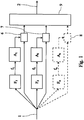
- Figure 1 shows a signal processing block diagram which accepts a peripheral pulse waveform as an input 1 and provides an estimated corresponding intra-arterial waveform as an output 2.
- Three filters F 1 , F 2 , F n are shown accepting the input 1.
- One of the filters F n and its associated components A n , 8 are optional and this is denoted by them being drawn using broken lines.
- Each filter F 1 , F 2 , F n is tuned to a different frequency associated with a specific phase of the peripheral pulse waveform.
- the output signal of each filter f 1 , f 2 , f n is amplified and each of the amplified filter output signals is added to the input signal.
- An amplifier A 1 , A 2 , A n may amplify its associated filter output f 1 , f 2 , f n with a gain greater, equal or less than 1.
- the amplified filter output is combined with the input signal using components 6, 7, 8.
- the outputs of the combining components are reconstructed to form an estimated intra-arterial waveform at the output 2.
- the output signal will correspond to the input signal, however, each component of the input waveform corresponding to a specific phase of the pulse waveform will be transformed by the filtration and amplification process.
- the optional components and connections of Figure 1 may be included to provide three filtered paths.
- This embodiment of the invention may also include other filtered paths in addition to the optional filter path shown.
- Each filter path including those shown and those described as being additional to those shown, is arranged to filter and amplify a specific phase of the peripheral phase waveform input to the signal processing circuit.
- the amplifiers A 1 , A 2 , A n are shown as being separate to the filters F 1 , F 2 , F n , but may in fact be combined with the filters to, whereby each filter F 1 , F 2 , F n is arranged to also provide a gain.
- An additional filter (not shown) may be provided at the output 2 the signal processing circuit. This additional filter is be arranged to smooth the reconstructed signal provided at the output 2.
- the filtered and amplified signals of Figure 1 may be reconstructed by mixing or by multiplexing.
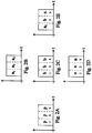
- Figures 2A to 2E illustrate how such a modulation process works.
- Figure 2A illustrates an example input signal provided at the input 1 of Figure 1 .
- the vertical axes of each of the graphs of Figures 2A to 2E represent magnitude of an input signal and the horizontal axes represent time.
- FIG. 2A shows the input signal divided into three phases p 1 , p 2 , p 3 .
- Each phase p 1 , p 2 , p 3 corresponds to a phase of the peripheral pulse waveform.
- Each phase p 1 , p 2 , p 3 will have a different frequency characteristic compared to the other phases which are specific to that particular phase.
- Figures 2B, 2C and 2D represent respective signal outputs from the combining modules 6, 7, 8 of Figure 1 .
- the output of combining component 6 is illustrated in Figure 2B ; the output of combining component 7 is illustrated by Figure 2C ; and the output of combining component 8 is illustrated by Figure 2D .
- the outputs are different for each combining component 6, 7, 8 because of the different filtering and amplification characteristics of each filter and amplifier pair.
- the combined output signals are reconstructed by reconstruction block 9 which, in this embodiment, creates an estimated intra-arterial waveform by multiplexing the outputs.
- the output 2 of the reconstruction block 9 is illustrated in Figure 2E .
- the signal of Figure 2E like the signals of Figures 2A to 2D , has three phases a 1 , b 2 , n 3 , whereby each phase is provided by a different filter-amplifier pair. This process of multiplexing may be repeated indefinitely to provide continuous waves at the output 2 of the signal processing circuit of Figure 1 .
- the number of paths in the signal processing apparatus of Figure 1 may be increased and the number of separate phases in the peripheral pulse waveform which may processed separately before being reconstructed into an stimulated intra-arterial waveform would increase correspondingly.
- a filter receiving the output of the reconstruction block 9 may be included. This filter would smooth out any discontinuity between the multiplexed signal output.
- Figure 3 illustrates an embodiment of a signal processing circuit similar to that shown in Figure 1 .
- Blocks and features with functions corresponding to those of Figure 1 are numbered identically.
- the outputs of the amplifiers A 1 , A 2 , A n are combined with the original input 1 by the reconstruction block 9.
- that of Figure 9 has an additional connection coupling the input 1 to the reconstruction block 9.
- FIG. 4 illustrates another embodiment of a signal processing circuit in accordance with an embodiment of the invention which utilises a more complex filter F.
- the filter F receives an input signal from the input 1 and outputs a plurality of signals f 1 , f 2 , f n which are then amplified. In this embodiment, only a single filter is required.
- the filter F may be an electronic filter programmed by software. Although each filtered signal is shown as being amplified by separate amplifiers A 1 , A 2 , A n , the amplification of the filtered signals f 1 , f 2 , f n may be provided by the filter F.
- the filtered and amplified signals and the original unfiltered signal are then reconstructed by the reconstruction block 9.
- Figures 5 and 6 show a comparison between cSBP estimated from a cuff waveform and cSBP estimated from a tonometry waveform with the cuff waveforms calibrated by (1) using a GTF to first transform this waveform to a local peripheral intra-arterial waveform, (2) calibrating the local peripheral intra-arterial waveform with oscillometric measurements of pSBP and DBP, (3) obtaining MAPavwave from this calibrated local peripheral intra-arterial waveform and, (4) using MAPavwave and DBP to calibrate a central blood pressure waveform obtained from transforming the original cuff waveform.
- Figure 6 shows a mean difference ( ⁇ SD) of 2.2 ( ⁇ 5.2) mmHg between cSBP estimated from the cuff and cSBP estimated from the tonometry method.
- the upper and lower dashed lines of the figure represent the mean difference ⁇ (double the SD), i.e. ⁇ 10.4.
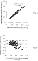
- Figures 7 and 8 show the results of an example of a method in accordance with the preferred method of transforming a cuff waveform to a local intra-arterial waveform as in the embodiment of the present invention.
- the method uses a cuff pressure measurement which has been gathered from a subject to reconstruct an arterial pulse waveform by extracting systolic and diastolic waveform phases from the cuff pressure waveform.
- Figure 7 shows a mean difference ( ⁇ SD) of 1.62 ( ⁇ 4.47) mmHg between cSBP estimated from the cuff and cSBP estimated from the tonometry method.
- the upper and lower dashed lines of the figure represent the mean difference ⁇ (double the SD), i.e. ⁇ 8.94.
- Figures 7 and 8 show a comparison between cSBP estimated from a cuff waveform and cSBP estimated from a tonometry waveform by (1) using the time division multiplexing method described below to transform the cuff waveform to a local peripheral intra-arterial waveform, (2) calibrating the local peripheral intra-arterial waveform with oscillometric measurements of pSBP and DBP, (3) obtaining MAPavwave from this calibrated local peripheral intra-arterial waveform, and (4) using MAPavwave and DBP to calibrate a central blood pressure waveform obtained from transforming the original cuff waveform.
- a first filter is applied to a cuff pressure waveform A in order to extract high frequency features which occur during a systole phase which are necessary to reconstruct the sharp upstroke of a peripheral intra-arterial pulse occurring during the systole phase.
- the result of the filtering is Waveform B.
- Waveform B is amplified and added to waveform A to obtain waveform C.
- Waveform C is a cuff waveform reconstructed to incorporate high frequency components in the systolic phase of the intra-arterial waveform which are lost in the cuff waveform.
- a second filter is applied to the cuff pressure waveform A in order to extract high frequency features necessary to reconstruct the diastolic part of the peripheral intra-arterial pulse.
- the result of the filtering is Waveform D.
- Waveform D is amplified and added to waveform A to obtain waveform E.
- Waveform E is a cuff waveform reconstructed to incorporate an exponential decay and a possible diastolic peak in the diastolic phase of the intra-arterial waveform which are lost in the cuff waveform.
- Pulse waveforms C and E are merged together to obtain a reconstructed arterial pulse.
- the systolic part of pulse C is used to re-construct the systolic part of the peripheral intra-arterial pulse and the diastolic part of pulse E to reconstruct the diastolic part of the peripheral intra-arterial pulse.
- a third filter is then applied to remove any point of discontinuity in the reconstructed arterial pulse.
- the third filter is preferably a zero phase filter.
- the following example was conducted in accordance with the above method.
- the example method and the tonometry method described in the introduction were performed on data gathered from 100 subjects. Three measurements were obtained from each subject using both methods.
- the example used a single MCP equal to MAP plus 50% of the difference between MAP and pSBP and sequential filtering applied to two phases of the cardiac cycle, sytstole and diastole.
- a seventh order Butterworth filter with a cut-off frequency 3.2Hz was used as the first filter to identify the highest frequencies during systole.
- the highest frequencies components of the systolic phase were amplified by a factor of 1.75 before being fed back to the original pulse.
- a Butterworth filter of the fourth order with a cut-off frequency of 1.75Hz was used as the second filter to identify the highest frequencies during diastole.
- the highest frequencies components of the diastolic phase were added to the original pulse.
- the third filter was a Butterworth low pass filter of the third order with a cut off frequency of 6 Hz.
- the white dots represent a set of data used to derive the filter characteristics of the example.
- the black diamonds represent a set of data used to validate the method (this set of data included the set of data used to derive the filter characteristics, hence some of the diamonds in the figures have corresponding circles plotted on them).
- the peripheral pulse waveform may be time divided into its different phases, such as the systolic phase and the diastolic phase prior to any filtration or other signal processing being applied thereto.
- the respective divided phase signals may then be processed as required, for example by being appropriately filtered, before then being recombined in a multiplex fashion.
Landscapes
- Health & Medical Sciences (AREA)
- Life Sciences & Earth Sciences (AREA)
- Cardiology (AREA)
- Engineering & Computer Science (AREA)
- Vascular Medicine (AREA)
- Public Health (AREA)
- Molecular Biology (AREA)
- Physics & Mathematics (AREA)
- Veterinary Medicine (AREA)
- Biophysics (AREA)
- Pathology (AREA)
- Biomedical Technology (AREA)
- Heart & Thoracic Surgery (AREA)
- Medical Informatics (AREA)
- Physiology (AREA)
- Surgery (AREA)
- Animal Behavior & Ethology (AREA)
- General Health & Medical Sciences (AREA)
- Ophthalmology & Optometry (AREA)
- Signal Processing (AREA)
- Psychiatry (AREA)
- Computer Vision & Pattern Recognition (AREA)
- Artificial Intelligence (AREA)
- Measuring Pulse, Heart Rate, Blood Pressure Or Blood Flow (AREA)
Applications Claiming Priority (2)
| Application Number | Priority Date | Filing Date | Title |
|---|---|---|---|
| GBGB1118644.2A GB201118644D0 (en) | 2011-10-27 | 2011-10-27 | A method and apparatus for measuring blood pressure |
| PCT/GB2012/052683 WO2013061089A1 (en) | 2011-10-27 | 2012-10-29 | A method and apparatus for measuring blood pressure |
Publications (2)
| Publication Number | Publication Date |
|---|---|
| EP2770905A1 EP2770905A1 (en) | 2014-09-03 |
| EP2770905B1 true EP2770905B1 (en) | 2019-08-07 |
Family
ID=45373575
Family Applications (1)
| Application Number | Title | Priority Date | Filing Date |
|---|---|---|---|
| EP12787060.8A Active EP2770905B1 (en) | 2011-10-27 | 2012-10-29 | A method and apparatus for measuring blood pressure |
Country Status (7)
Families Citing this family (3)
| Publication number | Priority date | Publication date | Assignee | Title |
|---|---|---|---|---|
| JP2543733B2 (ja) | 1987-11-25 | 1996-10-16 | 臼井国際産業株式会社 | スライド式排気ブレ―キ装置 |
| US11166643B2 (en) * | 2016-06-07 | 2021-11-09 | Michael F. O'Rourke | Non-invasive method of estimating intra-cranial pressure (ICP) |
| AU2018235369B2 (en) * | 2017-03-17 | 2022-11-03 | Atcor Medical Pty Ltd | Central aortic blood pressure and waveform calibration method |
Citations (1)
| Publication number | Priority date | Publication date | Assignee | Title |
|---|---|---|---|---|
| US6045510A (en) * | 1994-02-25 | 2000-04-04 | Colin Corporation | Blood pressure measuring apparatus |
Family Cites Families (20)
| Publication number | Priority date | Publication date | Assignee | Title |
|---|---|---|---|---|
| US5265011A (en) | 1989-04-03 | 1993-11-23 | Eastern Medical Testing Services, Inc. | Method for ascertaining the pressure pulse and related parameters in the ascending aorta from the contour of the pressure pulse in the peripheral arteries |
| JP2807024B2 (ja) | 1990-02-06 | 1998-09-30 | シチズン時計株式会社 | 電子血圧計 |
| US5560366A (en) | 1993-11-29 | 1996-10-01 | Colin Corporation | Oscillometric blood pressure measuring apparatus |
| JP3501492B2 (ja) * | 1994-04-05 | 2004-03-02 | 日本コーリン株式会社 | 血圧値推定機能を備えた自動血圧測定装置 |
| JP3637916B2 (ja) | 1995-11-01 | 2005-04-13 | セイコーエプソン株式会社 | 生体状態測定装置 |
| US6017313A (en) | 1998-03-20 | 2000-01-25 | Hypertension Diagnostics, Inc. | Apparatus and method for blood pressure pulse waveform contour analysis |
| JP3400417B2 (ja) | 2000-08-11 | 2003-04-28 | 日本コーリン株式会社 | 中枢動脈圧波形推定装置 |
| US6740045B2 (en) | 2001-04-19 | 2004-05-25 | Seiko Epson Corporation | Central blood pressure waveform estimation device and peripheral blood pressure waveform detection device |
| JP2003000555A (ja) * | 2001-04-19 | 2003-01-07 | Seiko Epson Corp | 中枢血圧波形推定装置および末梢血圧波形検出装置 |
| JP3774396B2 (ja) | 2001-11-19 | 2006-05-10 | コーリンメディカルテクノロジー株式会社 | オシロメトリック式自動血圧測定装置 |
| JP2005278965A (ja) | 2004-03-30 | 2005-10-13 | Yunekusu:Kk | 心機能評価装置 |
| JP2006000176A (ja) * | 2004-06-15 | 2006-01-05 | Omron Healthcare Co Ltd | 中枢血圧推定装置および方法 |
| GB0500430D0 (en) | 2005-01-10 | 2005-02-16 | Micro Medical Ltd | A method of obtaining an estimation of a person's aortic blood pressure |
| US20060224070A1 (en) | 2005-04-05 | 2006-10-05 | Sharrock Nigel E | System and method for non-invasive cardiovascular assessment from supra-systolic signals obtained with a wideband external pulse transducer in a blood pressure cuff |
| TWI258359B (en) | 2005-05-20 | 2006-07-21 | Dailycare Biomedical Inc | Apparatus for evaluating cardiovascular functions |
| US8469895B2 (en) | 2007-06-07 | 2013-06-25 | Healthstats International Pte Ltd | Deriving central aortic systolic pressure and analyzing arterial waveform data to derive central aortic systolic pressure values |
| TWI409051B (zh) | 2007-12-10 | 2013-09-21 | Univ Nat Yang Ming | 一種以壓脈帶測量肱動脈脈波震盪訊號以估算中央動脈血壓的測量裝置及其方法 |
| CN102026576A (zh) | 2008-05-15 | 2011-04-20 | 帕尔斯科尔有限公司 | 估测用测血压布袖袋得到的中心压力波形的方法 |
| GB0821084D0 (en) | 2008-11-18 | 2008-12-24 | King S College London | Apparatus and method |
| US20120157791A1 (en) * | 2010-12-16 | 2012-06-21 | General Electric Company | Adaptive time domain filtering for improved blood pressure estimation |
-
2011
- 2011-10-27 GB GBGB1118644.2A patent/GB201118644D0/en not_active Ceased
-
2012
- 2012-10-29 JP JP2014537733A patent/JP6234931B2/ja not_active Expired - Fee Related
- 2012-10-29 ES ES12787060T patent/ES2751938T3/es active Active
- 2012-10-29 WO PCT/GB2012/052683 patent/WO2013061089A1/en active Application Filing
- 2012-10-29 EP EP12787060.8A patent/EP2770905B1/en active Active
- 2012-10-29 HU HUE12787060A patent/HUE046018T2/hu unknown
- 2012-10-29 US US14/354,850 patent/US10159445B2/en active Active
Patent Citations (1)
| Publication number | Priority date | Publication date | Assignee | Title |
|---|---|---|---|---|
| US6045510A (en) * | 1994-02-25 | 2000-04-04 | Colin Corporation | Blood pressure measuring apparatus |
Also Published As
| Publication number | Publication date |
|---|---|
| ES2751938T3 (es) | 2020-04-02 |
| JP2014534023A (ja) | 2014-12-18 |
| US20140316288A1 (en) | 2014-10-23 |
| JP6234931B2 (ja) | 2017-11-22 |
| EP2770905A1 (en) | 2014-09-03 |
| US10159445B2 (en) | 2018-12-25 |
| HUE046018T2 (hu) | 2020-01-28 |
| GB201118644D0 (en) | 2011-12-07 |
| WO2013061089A1 (en) | 2013-05-02 |
Similar Documents
| Publication | Publication Date | Title |
|---|---|---|
| US12109008B2 (en) | Method of measuring central pressure waveform with features preserved | |
| CN107530005B (zh) | 用于导出对象的平均动脉压的方法和设备 | |
| US10213116B2 (en) | Methods for measuring blood pressure | |
| EP3609393B1 (en) | Non-invasive blood pressure measurement | |
| US20120157791A1 (en) | Adaptive time domain filtering for improved blood pressure estimation | |
| CN109512412B (zh) | 一种中心动脉血压测量装置 | |
| CN103479343A (zh) | 基于振荡式血压计信号的中心动脉压检测系统及方法 | |
| EP2770905B1 (en) | A method and apparatus for measuring blood pressure | |
| EP1835851A1 (en) | A method of obtaining an estimation of a person's aortic blood pressure | |
| CN103767694A (zh) | 一种准确提取袖带压力震荡波的方法 | |
| Singha et al. | An easy approach to develop a digital blood pressure meter | |
| Sahani et al. | Automatic estimation of carotid arterial pressure in ARTSENS | |
| Soueidan et al. | The effect of blood pressure variability on the estimation of the systolic and diastolic pressures | |
| US11529060B2 (en) | Method for determining time delay between beat-to-beat blood pressure signal and pulse arrival time | |
| Zhang et al. | A Generalized Transfer Function Method for Reconstruction of Continuous Brachial Artery Pressure Based on Digital Measurement | |
| Nikolić et al. | Assessing cerebral blood flow control from variability in blood pressure and arterial CO 2 levels | |
| Bikia et al. | Estimation of patient-specific central hemodynamic indices from brachial pressure and pulse wave velocity |
Legal Events
| Date | Code | Title | Description |
|---|---|---|---|
| PUAI | Public reference made under article 153(3) epc to a published international application that has entered the european phase |
Free format text: ORIGINAL CODE: 0009012 |
|
| 17P | Request for examination filed |
Effective date: 20140509 |
|
| AK | Designated contracting states |
Kind code of ref document: A1 Designated state(s): AL AT BE BG CH CY CZ DE DK EE ES FI FR GB GR HR HU IE IS IT LI LT LU LV MC MK MT NL NO PL PT RO RS SE SI SK SM TR |
|
| RAP1 | Party data changed (applicant data changed or rights of an application transferred) |
Owner name: SUNTECH MEDICAL, INC. |
|
| DAX | Request for extension of the european patent (deleted) | ||
| 17Q | First examination report despatched |
Effective date: 20150316 |
|
| STAA | Information on the status of an ep patent application or granted ep patent |
Free format text: STATUS: EXAMINATION IS IN PROGRESS |
|
| GRAP | Despatch of communication of intention to grant a patent |
Free format text: ORIGINAL CODE: EPIDOSNIGR1 |
|
| STAA | Information on the status of an ep patent application or granted ep patent |
Free format text: STATUS: GRANT OF PATENT IS INTENDED |
|
| INTG | Intention to grant announced |
Effective date: 20190219 |
|
| GRAS | Grant fee paid |
Free format text: ORIGINAL CODE: EPIDOSNIGR3 |
|
| GRAA | (expected) grant |
Free format text: ORIGINAL CODE: 0009210 |
|
| STAA | Information on the status of an ep patent application or granted ep patent |
Free format text: STATUS: THE PATENT HAS BEEN GRANTED |
|
| AK | Designated contracting states |
Kind code of ref document: B1 Designated state(s): AL AT BE BG CH CY CZ DE DK EE ES FI FR GB GR HR HU IE IS IT LI LT LU LV MC MK MT NL NO PL PT RO RS SE SI SK SM TR |
|
| REG | Reference to a national code |
Ref country code: GB Ref legal event code: FG4D |
|
| REG | Reference to a national code |
Ref country code: CH Ref legal event code: EP Ref country code: AT Ref legal event code: REF Ref document number: 1162583 Country of ref document: AT Kind code of ref document: T Effective date: 20190815 |
|
| REG | Reference to a national code |
Ref country code: DE Ref legal event code: R096 Ref document number: 602012062727 Country of ref document: DE |
|
| REG | Reference to a national code |
Ref country code: IE Ref legal event code: FG4D |
|
| REG | Reference to a national code |
Ref country code: CH Ref legal event code: NV Representative=s name: VALIPAT S.A. C/O BOVARD SA NEUCHATEL, CH |
|
| REG | Reference to a national code |
Ref country code: SE Ref legal event code: TRGR |
|
| REG | Reference to a national code |
Ref country code: NL Ref legal event code: FP |
|
| REG | Reference to a national code |
Ref country code: LT Ref legal event code: MG4D |
|
| REG | Reference to a national code |
Ref country code: HU Ref legal event code: AG4A Ref document number: E046018 Country of ref document: HU |
|
| PG25 | Lapsed in a contracting state [announced via postgrant information from national office to epo] |
Ref country code: BG Free format text: LAPSE BECAUSE OF FAILURE TO SUBMIT A TRANSLATION OF THE DESCRIPTION OR TO PAY THE FEE WITHIN THE PRESCRIBED TIME-LIMIT Effective date: 20191107 Ref country code: LT Free format text: LAPSE BECAUSE OF FAILURE TO SUBMIT A TRANSLATION OF THE DESCRIPTION OR TO PAY THE FEE WITHIN THE PRESCRIBED TIME-LIMIT Effective date: 20190807 Ref country code: HR Free format text: LAPSE BECAUSE OF FAILURE TO SUBMIT A TRANSLATION OF THE DESCRIPTION OR TO PAY THE FEE WITHIN THE PRESCRIBED TIME-LIMIT Effective date: 20190807 Ref country code: PT Free format text: LAPSE BECAUSE OF FAILURE TO SUBMIT A TRANSLATION OF THE DESCRIPTION OR TO PAY THE FEE WITHIN THE PRESCRIBED TIME-LIMIT Effective date: 20191209 Ref country code: FI Free format text: LAPSE BECAUSE OF FAILURE TO SUBMIT A TRANSLATION OF THE DESCRIPTION OR TO PAY THE FEE WITHIN THE PRESCRIBED TIME-LIMIT Effective date: 20190807 Ref country code: NO Free format text: LAPSE BECAUSE OF FAILURE TO SUBMIT A TRANSLATION OF THE DESCRIPTION OR TO PAY THE FEE WITHIN THE PRESCRIBED TIME-LIMIT Effective date: 20191107 |
|
| REG | Reference to a national code |
Ref country code: AT Ref legal event code: MK05 Ref document number: 1162583 Country of ref document: AT Kind code of ref document: T Effective date: 20190807 |
|
| PG25 | Lapsed in a contracting state [announced via postgrant information from national office to epo] |
Ref country code: LV Free format text: LAPSE BECAUSE OF FAILURE TO SUBMIT A TRANSLATION OF THE DESCRIPTION OR TO PAY THE FEE WITHIN THE PRESCRIBED TIME-LIMIT Effective date: 20190807 Ref country code: GR Free format text: LAPSE BECAUSE OF FAILURE TO SUBMIT A TRANSLATION OF THE DESCRIPTION OR TO PAY THE FEE WITHIN THE PRESCRIBED TIME-LIMIT Effective date: 20191108 Ref country code: IS Free format text: LAPSE BECAUSE OF FAILURE TO SUBMIT A TRANSLATION OF THE DESCRIPTION OR TO PAY THE FEE WITHIN THE PRESCRIBED TIME-LIMIT Effective date: 20191207 Ref country code: AL Free format text: LAPSE BECAUSE OF FAILURE TO SUBMIT A TRANSLATION OF THE DESCRIPTION OR TO PAY THE FEE WITHIN THE PRESCRIBED TIME-LIMIT Effective date: 20190807 Ref country code: RS Free format text: LAPSE BECAUSE OF FAILURE TO SUBMIT A TRANSLATION OF THE DESCRIPTION OR TO PAY THE FEE WITHIN THE PRESCRIBED TIME-LIMIT Effective date: 20190807 |
|
| PG25 | Lapsed in a contracting state [announced via postgrant information from national office to epo] |
Ref country code: TR Free format text: LAPSE BECAUSE OF FAILURE TO SUBMIT A TRANSLATION OF THE DESCRIPTION OR TO PAY THE FEE WITHIN THE PRESCRIBED TIME-LIMIT Effective date: 20190807 |
|
| REG | Reference to a national code |
Ref country code: ES Ref legal event code: FG2A Ref document number: 2751938 Country of ref document: ES Kind code of ref document: T3 Effective date: 20200402 |
|
| PG25 | Lapsed in a contracting state [announced via postgrant information from national office to epo] |
Ref country code: AT Free format text: LAPSE BECAUSE OF FAILURE TO SUBMIT A TRANSLATION OF THE DESCRIPTION OR TO PAY THE FEE WITHIN THE PRESCRIBED TIME-LIMIT Effective date: 20190807 Ref country code: RO Free format text: LAPSE BECAUSE OF FAILURE TO SUBMIT A TRANSLATION OF THE DESCRIPTION OR TO PAY THE FEE WITHIN THE PRESCRIBED TIME-LIMIT Effective date: 20190807 Ref country code: EE Free format text: LAPSE BECAUSE OF FAILURE TO SUBMIT A TRANSLATION OF THE DESCRIPTION OR TO PAY THE FEE WITHIN THE PRESCRIBED TIME-LIMIT Effective date: 20190807 Ref country code: PL Free format text: LAPSE BECAUSE OF FAILURE TO SUBMIT A TRANSLATION OF THE DESCRIPTION OR TO PAY THE FEE WITHIN THE PRESCRIBED TIME-LIMIT Effective date: 20190807 Ref country code: DK Free format text: LAPSE BECAUSE OF FAILURE TO SUBMIT A TRANSLATION OF THE DESCRIPTION OR TO PAY THE FEE WITHIN THE PRESCRIBED TIME-LIMIT Effective date: 20190807 |
|
| PG25 | Lapsed in a contracting state [announced via postgrant information from national office to epo] |
Ref country code: MC Free format text: LAPSE BECAUSE OF FAILURE TO SUBMIT A TRANSLATION OF THE DESCRIPTION OR TO PAY THE FEE WITHIN THE PRESCRIBED TIME-LIMIT Effective date: 20190807 Ref country code: SM Free format text: LAPSE BECAUSE OF FAILURE TO SUBMIT A TRANSLATION OF THE DESCRIPTION OR TO PAY THE FEE WITHIN THE PRESCRIBED TIME-LIMIT Effective date: 20190807 Ref country code: SK Free format text: LAPSE BECAUSE OF FAILURE TO SUBMIT A TRANSLATION OF THE DESCRIPTION OR TO PAY THE FEE WITHIN THE PRESCRIBED TIME-LIMIT Effective date: 20190807 Ref country code: IS Free format text: LAPSE BECAUSE OF FAILURE TO SUBMIT A TRANSLATION OF THE DESCRIPTION OR TO PAY THE FEE WITHIN THE PRESCRIBED TIME-LIMIT Effective date: 20200224 Ref country code: CZ Free format text: LAPSE BECAUSE OF FAILURE TO SUBMIT A TRANSLATION OF THE DESCRIPTION OR TO PAY THE FEE WITHIN THE PRESCRIBED TIME-LIMIT Effective date: 20190807 |
|
| REG | Reference to a national code |
Ref country code: DE Ref legal event code: R097 Ref document number: 602012062727 Country of ref document: DE |
|
| PLBE | No opposition filed within time limit |
Free format text: ORIGINAL CODE: 0009261 |
|
| STAA | Information on the status of an ep patent application or granted ep patent |
Free format text: STATUS: NO OPPOSITION FILED WITHIN TIME LIMIT |
|
| PG2D | Information on lapse in contracting state deleted |
Ref country code: IS |
|
| PG25 | Lapsed in a contracting state [announced via postgrant information from national office to epo] |
Ref country code: LU Free format text: LAPSE BECAUSE OF NON-PAYMENT OF DUE FEES Effective date: 20191029 |
|
| 26N | No opposition filed |
Effective date: 20200603 |
|
| REG | Reference to a national code |
Ref country code: BE Ref legal event code: MM Effective date: 20191031 |
|
| PG25 | Lapsed in a contracting state [announced via postgrant information from national office to epo] |
Ref country code: SI Free format text: LAPSE BECAUSE OF FAILURE TO SUBMIT A TRANSLATION OF THE DESCRIPTION OR TO PAY THE FEE WITHIN THE PRESCRIBED TIME-LIMIT Effective date: 20190807 Ref country code: BE Free format text: LAPSE BECAUSE OF NON-PAYMENT OF DUE FEES Effective date: 20191031 |
|
| PG25 | Lapsed in a contracting state [announced via postgrant information from national office to epo] |
Ref country code: CY Free format text: LAPSE BECAUSE OF FAILURE TO SUBMIT A TRANSLATION OF THE DESCRIPTION OR TO PAY THE FEE WITHIN THE PRESCRIBED TIME-LIMIT Effective date: 20190807 |
|
| PG25 | Lapsed in a contracting state [announced via postgrant information from national office to epo] |
Ref country code: MT Free format text: LAPSE BECAUSE OF FAILURE TO SUBMIT A TRANSLATION OF THE DESCRIPTION OR TO PAY THE FEE WITHIN THE PRESCRIBED TIME-LIMIT Effective date: 20190807 |
|
| PG25 | Lapsed in a contracting state [announced via postgrant information from national office to epo] |
Ref country code: MK Free format text: LAPSE BECAUSE OF FAILURE TO SUBMIT A TRANSLATION OF THE DESCRIPTION OR TO PAY THE FEE WITHIN THE PRESCRIBED TIME-LIMIT Effective date: 20190807 |
|
| PGFP | Annual fee paid to national office [announced via postgrant information from national office to epo] |
Ref country code: SE Payment date: 20220912 Year of fee payment: 11 Ref country code: NL Payment date: 20220916 Year of fee payment: 11 Ref country code: IE Payment date: 20220912 Year of fee payment: 11 Ref country code: GB Payment date: 20220908 Year of fee payment: 11 |
|
| PGFP | Annual fee paid to national office [announced via postgrant information from national office to epo] |
Ref country code: FR Payment date: 20220908 Year of fee payment: 11 |
|
| PGFP | Annual fee paid to national office [announced via postgrant information from national office to epo] |
Ref country code: IT Payment date: 20220913 Year of fee payment: 11 Ref country code: ES Payment date: 20221109 Year of fee payment: 11 Ref country code: DE Payment date: 20220906 Year of fee payment: 11 |
|
| PGFP | Annual fee paid to national office [announced via postgrant information from national office to epo] |
Ref country code: HU Payment date: 20220917 Year of fee payment: 11 Ref country code: CH Payment date: 20221010 Year of fee payment: 11 |
|
| P01 | Opt-out of the competence of the unified patent court (upc) registered |
Effective date: 20230510 |
|
| REG | Reference to a national code |
Ref country code: DE Ref legal event code: R119 Ref document number: 602012062727 Country of ref document: DE |
|
| REG | Reference to a national code |
Ref country code: SE Ref legal event code: EUG |
|
| REG | Reference to a national code |
Ref country code: CH Ref legal event code: PL |
|
| REG | Reference to a national code |
Ref country code: NL Ref legal event code: MM Effective date: 20231101 |
|
| GBPC | Gb: european patent ceased through non-payment of renewal fee |
Effective date: 20231029 |
|
| PG25 | Lapsed in a contracting state [announced via postgrant information from national office to epo] |
Ref country code: GB Free format text: LAPSE BECAUSE OF NON-PAYMENT OF DUE FEES Effective date: 20231029 |
|
| PG25 | Lapsed in a contracting state [announced via postgrant information from national office to epo] |
Ref country code: NL Free format text: LAPSE BECAUSE OF NON-PAYMENT OF DUE FEES Effective date: 20231101 Ref country code: CH Free format text: LAPSE BECAUSE OF NON-PAYMENT OF DUE FEES Effective date: 20231031 |
|
| PG25 | Lapsed in a contracting state [announced via postgrant information from national office to epo] |
Ref country code: NL Free format text: LAPSE BECAUSE OF NON-PAYMENT OF DUE FEES Effective date: 20231101 Ref country code: GB Free format text: LAPSE BECAUSE OF NON-PAYMENT OF DUE FEES Effective date: 20231029 Ref country code: FR Free format text: LAPSE BECAUSE OF NON-PAYMENT OF DUE FEES Effective date: 20231031 Ref country code: DE Free format text: LAPSE BECAUSE OF NON-PAYMENT OF DUE FEES Effective date: 20240501 Ref country code: CH Free format text: LAPSE BECAUSE OF NON-PAYMENT OF DUE FEES Effective date: 20231031 |
|
| PG25 | Lapsed in a contracting state [announced via postgrant information from national office to epo] |
Ref country code: SE Free format text: LAPSE BECAUSE OF NON-PAYMENT OF DUE FEES Effective date: 20231030 Ref country code: HU Free format text: LAPSE BECAUSE OF NON-PAYMENT OF DUE FEES Effective date: 20231030 |
|
| PG25 | Lapsed in a contracting state [announced via postgrant information from national office to epo] |
Ref country code: IE Free format text: LAPSE BECAUSE OF NON-PAYMENT OF DUE FEES Effective date: 20231029 |
|
| PG25 | Lapsed in a contracting state [announced via postgrant information from national office to epo] |
Ref country code: IE Free format text: LAPSE BECAUSE OF NON-PAYMENT OF DUE FEES Effective date: 20231029 |
|
| PG25 | Lapsed in a contracting state [announced via postgrant information from national office to epo] |
Ref country code: IT Free format text: LAPSE BECAUSE OF NON-PAYMENT OF DUE FEES Effective date: 20231029 |
|
| REG | Reference to a national code |
Ref country code: ES Ref legal event code: FD2A Effective date: 20241209 |
|
| PG25 | Lapsed in a contracting state [announced via postgrant information from national office to epo] |
Ref country code: IT Free format text: LAPSE BECAUSE OF NON-PAYMENT OF DUE FEES Effective date: 20231029 |
|
| PG25 | Lapsed in a contracting state [announced via postgrant information from national office to epo] |
Ref country code: ES Free format text: LAPSE BECAUSE OF NON-PAYMENT OF DUE FEES Effective date: 20231030 |
|
| PG25 | Lapsed in a contracting state [announced via postgrant information from national office to epo] |
Ref country code: ES Free format text: LAPSE BECAUSE OF NON-PAYMENT OF DUE FEES Effective date: 20231030 |