EP2770873B1 - Trägerstruktur für tische und tisch mit dieser trägerstruktur - Google Patents
Trägerstruktur für tische und tisch mit dieser trägerstruktur Download PDFInfo
- Publication number
- EP2770873B1 EP2770873B1 EP12707145.4A EP12707145A EP2770873B1 EP 2770873 B1 EP2770873 B1 EP 2770873B1 EP 12707145 A EP12707145 A EP 12707145A EP 2770873 B1 EP2770873 B1 EP 2770873B1
- Authority
- EP
- European Patent Office
- Prior art keywords
- supporting surface
- bearing
- suited
- connection
- bearing structure
- Prior art date
- Legal status (The legal status is an assumption and is not a legal conclusion. Google has not performed a legal analysis and makes no representation as to the accuracy of the status listed.)
- Not-in-force
Links
- 230000008878 coupling Effects 0.000 claims description 18
- 238000010168 coupling process Methods 0.000 claims description 18
- 238000005859 coupling reaction Methods 0.000 claims description 18
- 238000006073 displacement reaction Methods 0.000 claims description 10
- 230000006978 adaptation Effects 0.000 claims description 9
- 238000004519 manufacturing process Methods 0.000 description 6
- 238000003860 storage Methods 0.000 description 4
- 239000000463 material Substances 0.000 description 3
- 238000000034 method Methods 0.000 description 2
- 238000004026 adhesive bonding Methods 0.000 description 1
- XAGFODPZIPBFFR-UHFFFAOYSA-N aluminium Chemical compound [Al] XAGFODPZIPBFFR-UHFFFAOYSA-N 0.000 description 1
- 229910052782 aluminium Inorganic materials 0.000 description 1
- 239000004411 aluminium Substances 0.000 description 1
- 238000010276 construction Methods 0.000 description 1
- 239000011521 glass Substances 0.000 description 1
- 230000001105 regulatory effect Effects 0.000 description 1
- 230000000284 resting effect Effects 0.000 description 1
- 239000002023 wood Substances 0.000 description 1
Images




Classifications
-
- A—HUMAN NECESSITIES
- A47—FURNITURE; DOMESTIC ARTICLES OR APPLIANCES; COFFEE MILLS; SPICE MILLS; SUCTION CLEANERS IN GENERAL
- A47B—TABLES; DESKS; OFFICE FURNITURE; CABINETS; DRAWERS; GENERAL DETAILS OF FURNITURE
- A47B3/00—Folding or stowable tables
- A47B3/08—Folding or stowable tables with legs pivoted to top or underframe
- A47B3/0809—Folding or stowable tables with legs pivoted to top or underframe with elastic locking means
-
- A—HUMAN NECESSITIES
- A47—FURNITURE; DOMESTIC ARTICLES OR APPLIANCES; COFFEE MILLS; SPICE MILLS; SUCTION CLEANERS IN GENERAL
- A47B—TABLES; DESKS; OFFICE FURNITURE; CABINETS; DRAWERS; GENERAL DETAILS OF FURNITURE
- A47B3/00—Folding or stowable tables
- A47B3/08—Folding or stowable tables with legs pivoted to top or underframe
- A47B3/0809—Folding or stowable tables with legs pivoted to top or underframe with elastic locking means
- A47B3/0815—Folding or stowable tables with legs pivoted to top or underframe with elastic locking means the resilient force of the elastic locking means acting in a direction perpendicular to the axis of rotation of the leg
-
- A—HUMAN NECESSITIES
- A47—FURNITURE; DOMESTIC ARTICLES OR APPLIANCES; COFFEE MILLS; SPICE MILLS; SUCTION CLEANERS IN GENERAL
- A47B—TABLES; DESKS; OFFICE FURNITURE; CABINETS; DRAWERS; GENERAL DETAILS OF FURNITURE
- A47B7/00—Tables of rigid construction
- A47B7/02—Stackable tables; Nesting tables
-
- A—HUMAN NECESSITIES
- A47—FURNITURE; DOMESTIC ARTICLES OR APPLIANCES; COFFEE MILLS; SPICE MILLS; SUCTION CLEANERS IN GENERAL
- A47B—TABLES; DESKS; OFFICE FURNITURE; CABINETS; DRAWERS; GENERAL DETAILS OF FURNITURE
- A47B2200/00—General construction of tables or desks
- A47B2200/0035—Tables or desks with features relating to adjustability or folding
- A47B2200/0036—Table tops pivotable around longitudinal axis
Definitions
- the present invention relates to the sector of furniture.
- the present invention concerns the field of table production.
- the present invention concerns a bearing structure for tables with tilting top.
- Tables are known in the state of the art, in which the supporting plane is of the tilting type, meaning that during normal usage the supporting plane is in horizontal position, while it can assume a vertical or substantially vertical position when it is not in use.
- the table In the configuration in which it is not in use, the table has reduced overall dimensions and can be comfortably stored and kept ready to be used at a later moment.
- the bearing structures of the tables carried out according to the known technique are provided with a mechanical tilting system suited to be activated by the user that when necessary makes it possible to position the supporting plane in the above mentioned horizontal and vertical positions.
- the bearing structures of known type are made to measure and sized so as to guarantee the desired mechanical resistance and the desired stability. Said stability is obtained, in particular, by arranging the feet of the bearing structure at suitable distances from one another.
- bearing structures of the type above described are known from documents DE3800151A1 and EP1308109A1 .
- a drawback posed by the tables with tilting tops of known type lies in the construction complexity deriving from the need to provide different bearing structures depending on the size of the supporting plane to which they are applied.
- the main object of the present invention is thus to solve or at least partially overcome the problems mentioned above that characterize the bearing structures of known type.
- the present invention is based on the general consideration that the problems found in the state of the art can be at least partially overcome by means of a bearing structure for a supporting surface that can be adapted to supporting surfaces of different types.
- This problem is solved by the bearing structure according to claim 1.
- the adaptation means comprise displacement means suited to move the contact areas of the bearing means near or away from one another.
- the adaptation means preferably comprise displacement means suited to move the connection areas near or away from one another.
- the displacement means comprise telescopic means.
- connection means suitably comprise two or more brackets suitable for connection to the supporting surface.
- the displacement means comprise means for rotating the connection means.
- the structure comprises locking means associated with the displacement means in order to allow them to be locked in the first position.
- the locking means comprise two handles arranged on different areas of the bearing structure.
- the adaptation means preferably comprise displacement means suited to move the manoeuvring elements near or away from one another.
- the bearing means comprise two or more legs and the adaptation means comprise one or more interconnection elements of the telescopic type.
- the condition of usage of the supporting surface suitably corresponds to the horizontal position of the supporting surface.
- the condition in which the supporting surface is not in use preferably corresponds to the substantially vertical arrangement of the supporting surface.
- it concerns a furniture element comprising a supporting surface and a bearing structure for the supporting surface, wherein the bearing structure is of the type described above.
- Said furniture element is preferably constituted by a table.
- the present invention can be especially but not exclusively used in the field of furniture.
- the present invention can be especially applied in the production of tables with tilting supporting plane.
- the present invention will be described below with particular reference to a bearing structure for a table with tilting supporting plane. It should however be noted that the present invention is not intended to be used exclusively for a table; on the contrary, the present invention can also be advantageously applied in all the cases where it is necessary to use a supporting plane that can be easily stored when not in use.
- the bearing structure 1 according to an embodiment of the present invention is represented when applied to a supporting plane 50 to define a table 100.
- Figure 1 the table 100 is shown in its usage configuration, with the supporting plane 50 in horizontal position.
- the table 100 is shown in the configuration ready for storage, that is, with the supporting plane 50 in vertical or substantially vertical position.
- the table 100 In the storage position shown in Figure 2 , in fact, the table 100 has reduced overall dimensions compared to the usage position, and it can be comfortably stored together with other similar tables, as shown in Figure 3 .
- the table 100 comprises a bearing structure 1 arranged under a supporting plane 50, as shown also in Figures 4 and 5 .
- the supporting plane 50 can consist of a panel in the desired shape, rectangular in the case at hand, and made of a material suitable for its specific use, for example wood, aluminium, glass, etc.
- the bearing structure 1, too, will be made of a material suitable for the purpose, which will be able to ensure that the tables 100 has the desired mechanical resistance, the desired lightness and the desired stability in both the conditions described above, that is, with the supporting plane 50 in horizontal or vertical position.
- the bearing structure 1 comprises an upper area 2 for connection to the supporting plane 50 and a lower area 3 for resting the structure on the ground.
- the lower area 3 comprises contact points 4a-4d, four in the embodiment illustrated herein, suited to give stability to the table 100.
- the contact areas 4a-4d are constituted by the ends of corresponding legs 6a-6d and are substantially arranged at the vertices of a rectangle.
- the ends of the legs 6a-6d are preferably provided with wheels 7a-7d suited to facilitate the movements of the table 100.
- at least one of said wheels 7a-7d is provided with a brake element, not illustrated in the figures, suited to lock the table 100 in position once it has been positioned in the desired place.
- the table legs may not be provided with wheels.
- the four legs 6a-6b are advantageously connected to each other in pairs.
- the upper portion 8a, 8c of a leg is joined to the upper portion 8b, 8d of the other leg arranged on the same side of the table 100 in a corresponding union area 9, 10.
- connection means indicated as a whole by 15.
- connection means 15 comprise two side brackets 16, 17 suited to be integrally joined to the supporting plane 50, for example through fixing screws not illustrated in the figures. According to variant embodiments of the invention, said connection can be carried out through different and suitable connection means, for example by glueing, with snap-in connection means, with closure through clamps, clips or rivets.
- the two side brackets 16, 17 are connected to each other through a horizontal connection structure 18, described more clearly below.
- the side brackets 16, 17 and the horizontal connection structure 18 can be rotated with respect to the legs 6a-6d in order to allow the supporting plane 50 to be arranged in the horizontal and vertical usage positions.
- the side brackets 16, 17 and the horizontal connection structure 18 can be rotated around an axis X with respect to the horizontal connection structure 11 of the legs 6a-6d.
- each side bracket 16, 17 is articulated through a rotation pin 22, 23 with a corresponding projecting bearing element 20, 21 of the horizontal connection structure 11 of the legs 6a-6d.
- the supporting plane 50 can thus be arranged from the horizontal position to the vertical position, and vice versa, through its rotation around the rotation pins 22, 23. Said rotation pins 22, 23 are therefore aligned along the above mentioned rotation axis X.
- a locking device 24 allows the supporting plane 50 to be maintained safely and securely in its horizontal position.
- the same device 24, which can be operated manually, allows the supporting plane 50 to be released and brought to the vertical position.
- the locking device 24 comprises two coupling elements, only one of which is shown in the Figures from 7 to 9 and indicated by number 25, suited to be engaged in corresponding coupling seats 26, 27 obtained in the projecting bearing element 20, 21.
- Each coupling element 25 can be positioned in a coupling configuration, as shown in Figure 7 , in which it is housed in the corresponding coupling seat 26, 27 in the projecting bearing element 20, 21. In this coupling configuration, the supporting plane 50 is maintained securely and stably in horizontal position.
- the coupling elements 25 can be rotated through corresponding manoeuvring elements 28, 29 constituted by handles.
- one of the two handles 28, 29 allows the rotation of both the coupling elements 25 in order to enable them to be released from the coupling seat 26, 27 in the bearing element 20, 21, as shown in Figure 8 , and thus make the supporting plane 50 free to be rotated around the rotation pins 22, 23.
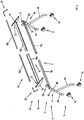
- the horizontal connection structure 11 of the union areas 9, 10 of the two pairs of legs 6a, 6b and 6c, 6d preferably comprises two tubular portions 11a, 11b that can be coupled with and engaged in each other in a telescopic way.
- the two tubular portions 11a, 11b are preferably maintained at the desired distance by means of suitable locking elements, not shown in the figure, like for example locking pins, fixing screws, with closure through clamps, clips or rivets.
- Said horizontal connection structure 11 of the telescopic type allows the distance between the legs 6a-6d of the bearing structure 1 to be regulated. This makes it possible to adapt the same bearing structure 1 to different measures of the supporting plane 50 guaranteeing the correct distance between the legs 6a-6d and the consequent stability of the table 100.
- the horizontal connection structure 18 of the side brackets 16, 17 preferably comprises two portions 18a, 18b that can be coupled to each other in a telescopic way.
- the two portions 18a, 18b have a conjugated V-shaped profile.
- the two V-shaped portions 18a, 18b are preferably maintained at the desired distance by means of suitable locking means, not shown in the figure, like for example locking pins, fixing screws, with closure through clamps, clips or rivets.
- the interconnection element 30 of the handles 28, 29 preferably comprises two tubular portions 30a, 30b that can be coupled to and inserted in each other in a telescopic way.
- the two tubular portions 30a, 30b preferably have a conjugated shape, substantially square in the embodiment illustrated herein, suited to allow their integral rotation when one of the two handles 28, 29 to which they are connected is rotated.
- the locking device 24 will be arranged at the correct distance and at the level of the projecting bearing elements 20, 21.
- the two tubular portions 30a, 30b are preferably maintained at the selected distance by means of suitable locking means, not shown in the figure, like for example locking pins, fixing screws, with closure through clamps, clips or rivets.
- suitable locking means not shown in the figure, like for example locking pins, fixing screws, with closure through clamps, clips or rivets.
- the locking device may be different from the one described herein.
Landscapes
- Furniture Connections (AREA)
- Pallets (AREA)
Claims (11)
- Tragstruktur (1) für eine Trägerfläche (50), Folgendes umfassend:- Stützmittel (6a, 6b, 6c, 6d), dazu geeignet, am Boden von einem oder mehreren Kontaktbereichen (4a, 4b, 4c, 4d) positioniert zu werden und zwei oder mehrere Beine umfassend;- Verbindungsmittel (15), dazu geeignet, die besagten Stützmittel (6a, 6b, 6c, 6d) in zwei oder mehreren Verbindungsbereichen mit der besagten Trägerfläche (50) zu verbinden;- Mittel zur Bewegung der besagten Verbindungsmittel (15), dazu geeignet zu erlauben, dass diese in einer ersten Position positioniert werden können, welche einer Bedingung der Benutzung der besagten Trägerfläche (50) entspricht, sowie in einer zweiten Position, die einer Bedingung entspricht, in der die besagte Trägerfläche (50) nicht benutzt wird,- Verriegelungsmittel (24), die so mit den besagten Bewegungsmitteln verbunden sind, dass diese in der besagten ersten Position blockiert werden können,- zwei Kupplungsaufnahmen (26, 27), die aus hervorstehenden Stützelementen (20,21) gewonnen sind, um mit einem entsprechenden Kupplungselement in Eingriff zu gelangen, wobei besagte Verriegelungsmittel (24) zwei Griffe (28, 29) umfassen, die in unterschiedlichen Bereichen der besagten Tragstruktur (1) angeordnet sind, undwobei die besagten Verriegelungsmittel (24) zwei Kupplungselemente (25) umfassen, die geeignet sind, in einer Kupplungskonfiguration positioniert zu werden, in welcher die Trägerebene (50) sicher und stabil in waagerechter Position gehalten wird, und wobei die Kupplungselemente (25) mittels der Griffe (28, 29) gedreht werden können, wobei sie Anpassungsmittel (11) umfasst, die geeignet sind zu erlauben, dass die besagte Tragstruktur (1) sich unterschiedlichen Abmessungen der besagten Trägerfläche (50) anpasst, wobei die besagten Anpassungsmittel (11) ein oder mehrere Verbindungselemente (11a, 11b) vom teleskopischen Typ umfassen, dadurch gekennzeichnet, dass sie ein Verbindungselement (30) umfasst, das die Griffe (28, 29) verbindet, wobei das Verbindungselement (30) zwei röhrenförmige Abschnitte (30a, 30b) umfasst, die teleskopisch aneinander gekoppelt und ineinander eingesteckt werden können.
- Struktur (1) nach Patentanspruch 1, dadurch gekennzeichnet, dass die besagten Anpassungsmittel Verschiebemittel umfassen, die geeignet sind, die besagten Kontaktbereiche (4a, 4b, 4c, 4d) der besagten Stützmittel (6a, 6b, 6c, 6d) aufeinander zu oder voneinander weg zu bewegen.
- Struktur (1) nach Patentanspruch 1 oder 2, dadurch gekennzeichnet, dass die besagten Anpassungsmittel Verschiebemittel umfassen, die geeignet sind, die besagten Verbindungsbereiche aufeinander zu oder voneinander weg zu bewegen.
- Struktur (1) nach Patentanspruch 2 oder 3, dadurch gekennzeichnet, dass die besagten Verschiebemittel (10) teleskopische Mittel umfassen.
- Struktur (1) nach einem jeden der vorstehenden Patentansprüche, dadurch gekennzeichnet, dass die besagten Verbindungsmittel (15) zwei oder mehr Bügel (16, 17) umfassen, die zur Verbindung mit der besagten Trägerfläche (50) geeignet sind.
- Struktur (1) gemäß eines jeden der vorstehenden Patentansprüche, dadurch gekennzeichnet, dass die besagten Bewegungsmittel Mittel zur Drehung der besagten Verbindungsmittel (15) umfassen.
- Struktur (1) nach einem jeden der vorstehenden Patentansprüche, dadurch gekennzeichnet, dass die besagten Anpassungsmittel Verschiebemittel umfassen, die geeignet sind, die besagten Griffe (28, 29) aufeinander zu oder voneinander weg zu bewegen.
- Struktur (1) nach einem jeden der vorstehenden Patentansprüche, dadurch gekennzeichnet, dass die besagte Bedingung der Benutzung der besagten Trägerfläche (50) der waagerechten Anordnung der besagten Trägerfläche (50) entspricht.
- Struktur (1) nach einem jeden der vorstehenden Patentansprüche, dadurch gekennzeichnet, dass die besagte Bedingung, in der die besagte Trägerfläche (50) nicht benutzt wird, der im Wesentlichen senkrechten Anordnung der besagten Trägerfläche (50) entspricht.
- Einrichtungselement (100), eine Trägerfläche (50) und eine Tragstruktur (1) für die besagte Trägerfläche (50) umfassend, dadurch gekennzeichnet, dass die besagte Tragstruktur (1) eine Tragstruktur (1) nach einem jeden der vorstehenden Patentansprüche ist.
- Einrichtungselement (100) nach Patentanspruch 10, dadurch gekennzeichnet, dass es aus einem Tisch (100) besteht.
Applications Claiming Priority (2)
| Application Number | Priority Date | Filing Date | Title |
|---|---|---|---|
| IT000289A ITVI20110289A1 (it) | 2011-10-28 | 2011-10-28 | Struttura di supporto per tavoli e tavolo comprendente tale struttura di supporto. |
| PCT/IT2012/000003 WO2013061345A1 (en) | 2011-10-28 | 2012-01-05 | Support structure for tables and table comprising said support structure |
Publications (2)
| Publication Number | Publication Date |
|---|---|
| EP2770873A1 EP2770873A1 (de) | 2014-09-03 |
| EP2770873B1 true EP2770873B1 (de) | 2018-08-22 |
Family
ID=45809530
Family Applications (1)
| Application Number | Title | Priority Date | Filing Date |
|---|---|---|---|
| EP12707145.4A Not-in-force EP2770873B1 (de) | 2011-10-28 | 2012-01-05 | Trägerstruktur für tische und tisch mit dieser trägerstruktur |
Country Status (3)
| Country | Link |
|---|---|
| EP (1) | EP2770873B1 (de) |
| IT (1) | ITVI20110289A1 (de) |
| WO (1) | WO2013061345A1 (de) |
Families Citing this family (3)
| Publication number | Priority date | Publication date | Assignee | Title |
|---|---|---|---|---|
| JP6425880B2 (ja) * | 2013-11-08 | 2018-11-21 | 株式会社内田洋行 | スタックテーブル、及びレバー |
| CN106213793B (zh) * | 2016-08-30 | 2019-10-25 | 宁波渠成进出口有限公司 | 可收折的桌子 |
| WO2018081415A1 (en) | 2016-10-27 | 2018-05-03 | Steelcase Inc. | Flip top table |
Family Cites Families (4)
| Publication number | Priority date | Publication date | Assignee | Title |
|---|---|---|---|---|
| CH673208A5 (de) * | 1987-09-03 | 1990-02-28 | Schaffner Ag | |
| DE10154308A1 (de) * | 2001-11-05 | 2003-05-15 | Wini Bueromoebel Georg Schmidt | Klapptischeinheit |
| AT411419B (de) * | 2002-05-24 | 2004-01-26 | Wiesner Hager Moebel Kg | Möbel, insbesondere tisch |
| GB0409409D0 (en) * | 2004-04-28 | 2004-06-02 | Senator Internat Ltd | A mechanism and a table incorporating such a mechanism |
-
2011
- 2011-10-28 IT IT000289A patent/ITVI20110289A1/it unknown
-
2012
- 2012-01-05 EP EP12707145.4A patent/EP2770873B1/de not_active Not-in-force
- 2012-01-05 WO PCT/IT2012/000003 patent/WO2013061345A1/en not_active Ceased
Non-Patent Citations (1)
| Title |
|---|
| None * |
Also Published As
| Publication number | Publication date |
|---|---|
| WO2013061345A1 (en) | 2013-05-02 |
| EP2770873A1 (de) | 2014-09-03 |
| ITVI20110289A1 (it) | 2012-01-27 |
Similar Documents
| Publication | Publication Date | Title |
|---|---|---|
| US8763537B2 (en) | Vertically elevated foldable frame | |
| KR101464114B1 (ko) | 접이식 의자가 달린 접이식 책상 | |
| EP2413748B1 (de) | Hochstuhl mit zusammenfaltbaren beinen | |
| CN102770046B (zh) | 物体的稳定 | |
| US20180160799A1 (en) | Height-adjustable desktop stand | |
| JP2013504378A (ja) | 腰掛付テーブル装置 | |
| US7845290B2 (en) | Nesting and folding table | |
| CN105793635A (zh) | 自稳定四腿底座 | |
| WO2013061345A1 (en) | Support structure for tables and table comprising said support structure | |
| KR20080003634U (ko) | 접이식 테이블의 절첩 구조 | |
| US9834987B2 (en) | Foldable picking ladder cart | |
| KR200472125Y1 (ko) | 가구의 사선형 다리 부착용 브라켓 및 이를 이용한 경첩 | |
| US6951369B1 (en) | Combination structure of swing chair used in yard | |
| US20040255829A1 (en) | Portable folding table | |
| CA3036545C (en) | Collapsible brace member for a furniture support structure | |
| KR200479046Y1 (ko) | 테이블의 절첩장치 | |
| EP3671000B1 (de) | Ein kompakter halter für ein fernsehkamera | |
| JP5503385B2 (ja) | ドーリー用車輪構造 | |
| KR101097100B1 (ko) | 의자 일체형 조립식 테이블 | |
| KR101440035B1 (ko) | 접이식 테이블 | |
| KR20110003025U (ko) | 절첩식 탁자의 절첩장치 | |
| KR101453844B1 (ko) | 와이어 선반용 코너 브라켓 | |
| JP3162594U (ja) | 家具の脚構造 | |
| KR200499161Y1 (ko) | 캠핑용 조립식 테이블 | |
| EP3542668B1 (de) | Zusammenklappbare beinanordnung mit einem zusammenklappbaren verstärkungselement für eine möbelstützstruktur |
Legal Events
| Date | Code | Title | Description |
|---|---|---|---|
| PUAI | Public reference made under article 153(3) epc to a published international application that has entered the european phase |
Free format text: ORIGINAL CODE: 0009012 |
|
| 17P | Request for examination filed |
Effective date: 20140522 |
|
| AK | Designated contracting states |
Kind code of ref document: A1 Designated state(s): AL AT BE BG CH CY CZ DE DK EE ES FI FR GB GR HR HU IE IS IT LI LT LU LV MC MK MT NL NO PL PT RO RS SE SI SK SM TR |
|
| DAX | Request for extension of the european patent (deleted) | ||
| 17Q | First examination report despatched |
Effective date: 20160804 |
|
| STAA | Information on the status of an ep patent application or granted ep patent |
Free format text: STATUS: EXAMINATION IS IN PROGRESS |
|
| GRAP | Despatch of communication of intention to grant a patent |
Free format text: ORIGINAL CODE: EPIDOSNIGR1 |
|
| STAA | Information on the status of an ep patent application or granted ep patent |
Free format text: STATUS: GRANT OF PATENT IS INTENDED |
|
| INTG | Intention to grant announced |
Effective date: 20180316 |
|
| GRAJ | Information related to disapproval of communication of intention to grant by the applicant or resumption of examination proceedings by the epo deleted |
Free format text: ORIGINAL CODE: EPIDOSDIGR1 |
|
| STAA | Information on the status of an ep patent application or granted ep patent |
Free format text: STATUS: EXAMINATION IS IN PROGRESS |
|
| GRAS | Grant fee paid |
Free format text: ORIGINAL CODE: EPIDOSNIGR3 |
|
| STAA | Information on the status of an ep patent application or granted ep patent |
Free format text: STATUS: GRANT OF PATENT IS INTENDED |
|
| GRAP | Despatch of communication of intention to grant a patent |
Free format text: ORIGINAL CODE: EPIDOSNIGR1 |
|
| GRAA | (expected) grant |
Free format text: ORIGINAL CODE: 0009210 |
|
| STAA | Information on the status of an ep patent application or granted ep patent |
Free format text: STATUS: THE PATENT HAS BEEN GRANTED |
|
| INTG | Intention to grant announced |
Effective date: 20180704 |
|
| RIN1 | Information on inventor provided before grant (corrected) |
Inventor name: CARRETTA, LUCIO |
|
| AK | Designated contracting states |
Kind code of ref document: B1 Designated state(s): AL AT BE BG CH CY CZ DE DK EE ES FI FR GB GR HR HU IE IS IT LI LT LU LV MC MK MT NL NO PL PT RO RS SE SI SK SM TR |
|
| REG | Reference to a national code |
Ref country code: GB Ref legal event code: FG4D |
|
| REG | Reference to a national code |
Ref country code: CH Ref legal event code: EP |
|
| REG | Reference to a national code |
Ref country code: AT Ref legal event code: REF Ref document number: 1031450 Country of ref document: AT Kind code of ref document: T Effective date: 20180915 |
|
| REG | Reference to a national code |
Ref country code: IE Ref legal event code: FG4D |
|
| REG | Reference to a national code |
Ref country code: DE Ref legal event code: R096 Ref document number: 602012050051 Country of ref document: DE |
|
| REG | Reference to a national code |
Ref country code: NL Ref legal event code: MP Effective date: 20180822 |
|
| REG | Reference to a national code |
Ref country code: LT Ref legal event code: MG4D |
|
| PG25 | Lapsed in a contracting state [announced via postgrant information from national office to epo] |
Ref country code: FI Free format text: LAPSE BECAUSE OF FAILURE TO SUBMIT A TRANSLATION OF THE DESCRIPTION OR TO PAY THE FEE WITHIN THE PRESCRIBED TIME-LIMIT Effective date: 20180822 Ref country code: RS Free format text: LAPSE BECAUSE OF FAILURE TO SUBMIT A TRANSLATION OF THE DESCRIPTION OR TO PAY THE FEE WITHIN THE PRESCRIBED TIME-LIMIT Effective date: 20180822 Ref country code: NO Free format text: LAPSE BECAUSE OF FAILURE TO SUBMIT A TRANSLATION OF THE DESCRIPTION OR TO PAY THE FEE WITHIN THE PRESCRIBED TIME-LIMIT Effective date: 20181122 Ref country code: IS Free format text: LAPSE BECAUSE OF FAILURE TO SUBMIT A TRANSLATION OF THE DESCRIPTION OR TO PAY THE FEE WITHIN THE PRESCRIBED TIME-LIMIT Effective date: 20181222 Ref country code: GR Free format text: LAPSE BECAUSE OF FAILURE TO SUBMIT A TRANSLATION OF THE DESCRIPTION OR TO PAY THE FEE WITHIN THE PRESCRIBED TIME-LIMIT Effective date: 20181123 Ref country code: SE Free format text: LAPSE BECAUSE OF FAILURE TO SUBMIT A TRANSLATION OF THE DESCRIPTION OR TO PAY THE FEE WITHIN THE PRESCRIBED TIME-LIMIT Effective date: 20180822 Ref country code: BG Free format text: LAPSE BECAUSE OF FAILURE TO SUBMIT A TRANSLATION OF THE DESCRIPTION OR TO PAY THE FEE WITHIN THE PRESCRIBED TIME-LIMIT Effective date: 20181122 Ref country code: NL Free format text: LAPSE BECAUSE OF FAILURE TO SUBMIT A TRANSLATION OF THE DESCRIPTION OR TO PAY THE FEE WITHIN THE PRESCRIBED TIME-LIMIT Effective date: 20180822 Ref country code: LT Free format text: LAPSE BECAUSE OF FAILURE TO SUBMIT A TRANSLATION OF THE DESCRIPTION OR TO PAY THE FEE WITHIN THE PRESCRIBED TIME-LIMIT Effective date: 20180822 |
|
| REG | Reference to a national code |
Ref country code: AT Ref legal event code: MK05 Ref document number: 1031450 Country of ref document: AT Kind code of ref document: T Effective date: 20180822 |
|
| PG25 | Lapsed in a contracting state [announced via postgrant information from national office to epo] |
Ref country code: HR Free format text: LAPSE BECAUSE OF FAILURE TO SUBMIT A TRANSLATION OF THE DESCRIPTION OR TO PAY THE FEE WITHIN THE PRESCRIBED TIME-LIMIT Effective date: 20180822 Ref country code: AL Free format text: LAPSE BECAUSE OF FAILURE TO SUBMIT A TRANSLATION OF THE DESCRIPTION OR TO PAY THE FEE WITHIN THE PRESCRIBED TIME-LIMIT Effective date: 20180822 Ref country code: LV Free format text: LAPSE BECAUSE OF FAILURE TO SUBMIT A TRANSLATION OF THE DESCRIPTION OR TO PAY THE FEE WITHIN THE PRESCRIBED TIME-LIMIT Effective date: 20180822 |
|
| PG25 | Lapsed in a contracting state [announced via postgrant information from national office to epo] |
Ref country code: ES Free format text: LAPSE BECAUSE OF FAILURE TO SUBMIT A TRANSLATION OF THE DESCRIPTION OR TO PAY THE FEE WITHIN THE PRESCRIBED TIME-LIMIT Effective date: 20180822 Ref country code: CZ Free format text: LAPSE BECAUSE OF FAILURE TO SUBMIT A TRANSLATION OF THE DESCRIPTION OR TO PAY THE FEE WITHIN THE PRESCRIBED TIME-LIMIT Effective date: 20180822 Ref country code: PL Free format text: LAPSE BECAUSE OF FAILURE TO SUBMIT A TRANSLATION OF THE DESCRIPTION OR TO PAY THE FEE WITHIN THE PRESCRIBED TIME-LIMIT Effective date: 20180822 Ref country code: RO Free format text: LAPSE BECAUSE OF FAILURE TO SUBMIT A TRANSLATION OF THE DESCRIPTION OR TO PAY THE FEE WITHIN THE PRESCRIBED TIME-LIMIT Effective date: 20180822 Ref country code: EE Free format text: LAPSE BECAUSE OF FAILURE TO SUBMIT A TRANSLATION OF THE DESCRIPTION OR TO PAY THE FEE WITHIN THE PRESCRIBED TIME-LIMIT Effective date: 20180822 Ref country code: AT Free format text: LAPSE BECAUSE OF FAILURE TO SUBMIT A TRANSLATION OF THE DESCRIPTION OR TO PAY THE FEE WITHIN THE PRESCRIBED TIME-LIMIT Effective date: 20180822 |
|
| REG | Reference to a national code |
Ref country code: DE Ref legal event code: R097 Ref document number: 602012050051 Country of ref document: DE |
|
| PG25 | Lapsed in a contracting state [announced via postgrant information from national office to epo] |
Ref country code: DK Free format text: LAPSE BECAUSE OF FAILURE TO SUBMIT A TRANSLATION OF THE DESCRIPTION OR TO PAY THE FEE WITHIN THE PRESCRIBED TIME-LIMIT Effective date: 20180822 Ref country code: SM Free format text: LAPSE BECAUSE OF FAILURE TO SUBMIT A TRANSLATION OF THE DESCRIPTION OR TO PAY THE FEE WITHIN THE PRESCRIBED TIME-LIMIT Effective date: 20180822 Ref country code: SK Free format text: LAPSE BECAUSE OF FAILURE TO SUBMIT A TRANSLATION OF THE DESCRIPTION OR TO PAY THE FEE WITHIN THE PRESCRIBED TIME-LIMIT Effective date: 20180822 |
|
| PLBE | No opposition filed within time limit |
Free format text: ORIGINAL CODE: 0009261 |
|
| STAA | Information on the status of an ep patent application or granted ep patent |
Free format text: STATUS: NO OPPOSITION FILED WITHIN TIME LIMIT |
|
| 26N | No opposition filed |
Effective date: 20190523 |
|
| PG25 | Lapsed in a contracting state [announced via postgrant information from national office to epo] |
Ref country code: SI Free format text: LAPSE BECAUSE OF FAILURE TO SUBMIT A TRANSLATION OF THE DESCRIPTION OR TO PAY THE FEE WITHIN THE PRESCRIBED TIME-LIMIT Effective date: 20180822 Ref country code: MC Free format text: LAPSE BECAUSE OF FAILURE TO SUBMIT A TRANSLATION OF THE DESCRIPTION OR TO PAY THE FEE WITHIN THE PRESCRIBED TIME-LIMIT Effective date: 20180822 |
|
| REG | Reference to a national code |
Ref country code: CH Ref legal event code: PL |
|
| PG25 | Lapsed in a contracting state [announced via postgrant information from national office to epo] |
Ref country code: LU Free format text: LAPSE BECAUSE OF NON-PAYMENT OF DUE FEES Effective date: 20190105 |
|
| REG | Reference to a national code |
Ref country code: BE Ref legal event code: MM Effective date: 20190131 |
|
| REG | Reference to a national code |
Ref country code: IE Ref legal event code: MM4A |
|
| PG25 | Lapsed in a contracting state [announced via postgrant information from national office to epo] |
Ref country code: BE Free format text: LAPSE BECAUSE OF NON-PAYMENT OF DUE FEES Effective date: 20190131 |
|
| PG25 | Lapsed in a contracting state [announced via postgrant information from national office to epo] |
Ref country code: CH Free format text: LAPSE BECAUSE OF NON-PAYMENT OF DUE FEES Effective date: 20190131 Ref country code: LI Free format text: LAPSE BECAUSE OF NON-PAYMENT OF DUE FEES Effective date: 20190131 |
|
| PG25 | Lapsed in a contracting state [announced via postgrant information from national office to epo] |
Ref country code: IE Free format text: LAPSE BECAUSE OF NON-PAYMENT OF DUE FEES Effective date: 20190105 |
|
| PG25 | Lapsed in a contracting state [announced via postgrant information from national office to epo] |
Ref country code: TR Free format text: LAPSE BECAUSE OF FAILURE TO SUBMIT A TRANSLATION OF THE DESCRIPTION OR TO PAY THE FEE WITHIN THE PRESCRIBED TIME-LIMIT Effective date: 20180822 |
|
| PGFP | Annual fee paid to national office [announced via postgrant information from national office to epo] |
Ref country code: IT Payment date: 20200124 Year of fee payment: 9 |
|
| PG25 | Lapsed in a contracting state [announced via postgrant information from national office to epo] |
Ref country code: PT Free format text: LAPSE BECAUSE OF FAILURE TO SUBMIT A TRANSLATION OF THE DESCRIPTION OR TO PAY THE FEE WITHIN THE PRESCRIBED TIME-LIMIT Effective date: 20181222 Ref country code: MT Free format text: LAPSE BECAUSE OF NON-PAYMENT OF DUE FEES Effective date: 20190105 |
|
| PGFP | Annual fee paid to national office [announced via postgrant information from national office to epo] |
Ref country code: GB Payment date: 20201223 Year of fee payment: 10 |
|
| PGFP | Annual fee paid to national office [announced via postgrant information from national office to epo] |
Ref country code: FR Payment date: 20210112 Year of fee payment: 10 |
|
| PG25 | Lapsed in a contracting state [announced via postgrant information from national office to epo] |
Ref country code: CY Free format text: LAPSE BECAUSE OF FAILURE TO SUBMIT A TRANSLATION OF THE DESCRIPTION OR TO PAY THE FEE WITHIN THE PRESCRIBED TIME-LIMIT Effective date: 20180822 |
|
| PGFP | Annual fee paid to national office [announced via postgrant information from national office to epo] |
Ref country code: DE Payment date: 20201222 Year of fee payment: 10 |
|
| PG25 | Lapsed in a contracting state [announced via postgrant information from national office to epo] |
Ref country code: HU Free format text: LAPSE BECAUSE OF FAILURE TO SUBMIT A TRANSLATION OF THE DESCRIPTION OR TO PAY THE FEE WITHIN THE PRESCRIBED TIME-LIMIT; INVALID AB INITIO Effective date: 20120105 |
|
| PG25 | Lapsed in a contracting state [announced via postgrant information from national office to epo] |
Ref country code: IT Free format text: LAPSE BECAUSE OF NON-PAYMENT OF DUE FEES Effective date: 20210105 |
|
| PG25 | Lapsed in a contracting state [announced via postgrant information from national office to epo] |
Ref country code: MK Free format text: LAPSE BECAUSE OF FAILURE TO SUBMIT A TRANSLATION OF THE DESCRIPTION OR TO PAY THE FEE WITHIN THE PRESCRIBED TIME-LIMIT Effective date: 20180822 |
|
| REG | Reference to a national code |
Ref country code: DE Ref legal event code: R119 Ref document number: 602012050051 Country of ref document: DE |
|
| GBPC | Gb: european patent ceased through non-payment of renewal fee |
Effective date: 20220105 |
|
| PG25 | Lapsed in a contracting state [announced via postgrant information from national office to epo] |
Ref country code: GB Free format text: LAPSE BECAUSE OF NON-PAYMENT OF DUE FEES Effective date: 20220105 Ref country code: DE Free format text: LAPSE BECAUSE OF NON-PAYMENT OF DUE FEES Effective date: 20220802 |
|
| PG25 | Lapsed in a contracting state [announced via postgrant information from national office to epo] |
Ref country code: FR Free format text: LAPSE BECAUSE OF NON-PAYMENT OF DUE FEES Effective date: 20220131 |