EP2770074A1 - Iron-based alloy for powder injection molding - Google Patents
Iron-based alloy for powder injection molding Download PDFInfo
- Publication number
- EP2770074A1 EP2770074A1 EP12841059.4A EP12841059A EP2770074A1 EP 2770074 A1 EP2770074 A1 EP 2770074A1 EP 12841059 A EP12841059 A EP 12841059A EP 2770074 A1 EP2770074 A1 EP 2770074A1
- Authority
- EP
- European Patent Office
- Prior art keywords
- alloy
- powder
- injection molding
- ferrous alloy
- chromium
- Prior art date
- Legal status (The legal status is an assumption and is not a legal conclusion. Google has not performed a legal analysis and makes no representation as to the accuracy of the status listed.)
- Withdrawn
Links
Images





Classifications
-
- C—CHEMISTRY; METALLURGY
- C22—METALLURGY; FERROUS OR NON-FERROUS ALLOYS; TREATMENT OF ALLOYS OR NON-FERROUS METALS
- C22C—ALLOYS
- C22C38/00—Ferrous alloys, e.g. steel alloys
- C22C38/18—Ferrous alloys, e.g. steel alloys containing chromium
- C22C38/34—Ferrous alloys, e.g. steel alloys containing chromium with more than 1.5% by weight of silicon
-
- C—CHEMISTRY; METALLURGY
- C22—METALLURGY; FERROUS OR NON-FERROUS ALLOYS; TREATMENT OF ALLOYS OR NON-FERROUS METALS
- C22C—ALLOYS
- C22C38/00—Ferrous alloys, e.g. steel alloys
- C22C38/60—Ferrous alloys, e.g. steel alloys containing lead, selenium, tellurium, or antimony, or more than 0.04% by weight of sulfur
-
- B—PERFORMING OPERATIONS; TRANSPORTING
- B22—CASTING; POWDER METALLURGY
- B22F—WORKING METALLIC POWDER; MANUFACTURE OF ARTICLES FROM METALLIC POWDER; MAKING METALLIC POWDER; APPARATUS OR DEVICES SPECIALLY ADAPTED FOR METALLIC POWDER
- B22F3/00—Manufacture of workpieces or articles from metallic powder characterised by the manner of compacting or sintering; Apparatus specially adapted therefor ; Presses and furnaces
- B22F3/12—Both compacting and sintering
-
- B—PERFORMING OPERATIONS; TRANSPORTING
- B22—CASTING; POWDER METALLURGY
- B22F—WORKING METALLIC POWDER; MANUFACTURE OF ARTICLES FROM METALLIC POWDER; MAKING METALLIC POWDER; APPARATUS OR DEVICES SPECIALLY ADAPTED FOR METALLIC POWDER
- B22F3/00—Manufacture of workpieces or articles from metallic powder characterised by the manner of compacting or sintering; Apparatus specially adapted therefor ; Presses and furnaces
- B22F3/22—Manufacture of workpieces or articles from metallic powder characterised by the manner of compacting or sintering; Apparatus specially adapted therefor ; Presses and furnaces for producing castings from a slip
- B22F3/225—Manufacture of workpieces or articles from metallic powder characterised by the manner of compacting or sintering; Apparatus specially adapted therefor ; Presses and furnaces for producing castings from a slip by injection molding
-
- C—CHEMISTRY; METALLURGY
- C22—METALLURGY; FERROUS OR NON-FERROUS ALLOYS; TREATMENT OF ALLOYS OR NON-FERROUS METALS
- C22C—ALLOYS
- C22C30/00—Alloys containing less than 50% by weight of each constituent
-
- C—CHEMISTRY; METALLURGY
- C22—METALLURGY; FERROUS OR NON-FERROUS ALLOYS; TREATMENT OF ALLOYS OR NON-FERROUS METALS
- C22C—ALLOYS
- C22C33/00—Making ferrous alloys
- C22C33/02—Making ferrous alloys by powder metallurgy
- C22C33/0257—Making ferrous alloys by powder metallurgy characterised by the range of the alloying elements
- C22C33/0278—Making ferrous alloys by powder metallurgy characterised by the range of the alloying elements with at least one alloying element having a minimum content above 5%
- C22C33/0285—Making ferrous alloys by powder metallurgy characterised by the range of the alloying elements with at least one alloying element having a minimum content above 5% with Cr, Co, or Ni having a minimum content higher than 5%
-
- C—CHEMISTRY; METALLURGY
- C22—METALLURGY; FERROUS OR NON-FERROUS ALLOYS; TREATMENT OF ALLOYS OR NON-FERROUS METALS
- C22C—ALLOYS
- C22C38/00—Ferrous alloys, e.g. steel alloys
- C22C38/18—Ferrous alloys, e.g. steel alloys containing chromium
- C22C38/32—Ferrous alloys, e.g. steel alloys containing chromium with boron
-
- C—CHEMISTRY; METALLURGY
- C22—METALLURGY; FERROUS OR NON-FERROUS ALLOYS; TREATMENT OF ALLOYS OR NON-FERROUS METALS
- C22C—ALLOYS
- C22C38/00—Ferrous alloys, e.g. steel alloys
- C22C38/18—Ferrous alloys, e.g. steel alloys containing chromium
- C22C38/40—Ferrous alloys, e.g. steel alloys containing chromium with nickel
- C22C38/42—Ferrous alloys, e.g. steel alloys containing chromium with nickel with copper
-
- C—CHEMISTRY; METALLURGY
- C22—METALLURGY; FERROUS OR NON-FERROUS ALLOYS; TREATMENT OF ALLOYS OR NON-FERROUS METALS
- C22C—ALLOYS
- C22C38/00—Ferrous alloys, e.g. steel alloys
- C22C38/18—Ferrous alloys, e.g. steel alloys containing chromium
- C22C38/40—Ferrous alloys, e.g. steel alloys containing chromium with nickel
- C22C38/48—Ferrous alloys, e.g. steel alloys containing chromium with nickel with niobium or tantalum
Definitions
- the present invention relates to a ferrous alloy, and more particularly, to a ferrous alloy for powder injection molding.
- Powder injection molding is new powder metallurgy molding technology in which powder metallurgy technology and an injection molding method, which is mass production technology of a precise plastic component, are coupled.
- a PIM process is a process of producing a component by mixing a micro-powder and a polymer binder to be a subject of flow, injecting the powder and the binder into a mold, removing the binder from the mix, and finally sintering only the powder at a high temperature.
- three-dimensional precision components may be made entirely of a powder material such as a metal, a ceramic, a carbide, and an intermetallic compound, and even of a processing resistant material or a material that cannot be cast, because mass production is available with few or no post-processes, so powder injection molding technology is appropriate for economically producing high value components.
- a powder material such as a metal, a ceramic, a carbide, and an intermetallic compound
- Stainless steel that occupies most of a metal powder injection molding market has a property of strength, hardness, abrasion resistance, and corrosion resistance that a final powder injection molding component requires with a change of chemical composition.
- a stainless steel powder that is used for powder injection molding variously exists as SUS304L, SUS316L, SUS430, and SUS630, and for martensite-based stainless steel powder injection molding, an additional heat treatment process is necessary.
- the present invention has been made in an effort to provide a ferrous alloy having advantages of representing superior hardness, abrasion resistance, and corrosion resistance than those of stainless steel that is used for existing powder injection molding and having a low production cost.
- An exemplary embodiment of the present invention provides a ferrous alloy for powder injection molding including: iron (Fe) at 52.59-78.15 wt%, chromium (Cr) at 16.45-37.34 wt%, boron (B) at 3.42-7.76 wt%, silicon (Si) at 1.64-1.92 wt%, sulfur (S) at 0-0.21 wt%, carbon (C) at 0.16-0.18 wt%, and other inevitable impurities.
- a ratio X Cr /X B of the chromium (Cr) and boron (B) may be 1.0.
- a sum (X Cr +X B ) of a composition of the chromium (Cr) and the boron (B) may be 0.30 to 0.60.
- a sum (X Fe +X Cr +X B ) of a composition of the iron (Fe), the chromium (Cr), and the boron (B) may be 0.9635.
- chromium boride may be distributed in a network form within a ferrite base.
- a volume fraction of the chromium boride (Cr 2 B) may be 51-91 %.
- Hardness of the ferrous alloy for powder injection molding may be 600-1600 VHN.
- Another embodiment of the present invention provides a method of injection molding a ferrous powder, the method including: providing powder of the ferrous alloy for powder injection molding; forming a powder mixture by mixing the powder of the ferrous alloy for powder injection molding and a binder; compression molding the powder mixture; removing the binder by heating the powder mixture; and sintering the powder mixture from which the binder is removed.
- the powder mixture may be formed by mixing the powder of the ferrous alloy for powder injection molding, paraffin wax, tungsten carbide balls, and heptanes in a container and rotating the container.
- Ferrous alloys for powder injection molding according to the present invention form hard Cr 2 B boride with different volume fractions, thereby greatly improving hardness and abrasion resistance, compared with a conventionally used stainless steel.
- ferrous alloys for powder injection molding according to the present invention are cheaper in alloy price than a commercial stainless steel by lowering a fraction of an alloy element, and by reducing production cost by lowering a sintering temperature and reducing sintering time, the ferrous alloys are superior in price competitiveness.
- a ferrous alloy for powder injection molding includes iron (Fe) at 52.59-78.15 wt%, chromium (Cr) at 16.45-37.34 wt%, boron (B) at 3.42-7.76 wt%, silicon (Si) at 1.64-1.92wt%, sulfur (S) at 0-0.21 wt%, carbon (C) at 0.16-0.18 wt%, and other inevitable impurities.
- a microstructure of the ferrous alloy is characterized in that chromium boride (Cr 2 B) is distributed in a network form within a ferrite base.
- a chromium boride (Cr 2 B) phase according to the present invention is very hard, a shape and a fraction distribution state of the precipitated chromium boride phase may have a direct influence on entire hardness and abrasion resistance of a specimen.
- a chromium boride phase of the ferrous alloy forms a network structure, an entire hardness distribution of the specimen is uniform according to a position, and an applied load in an abrasion environment is distributed to be superior in an abrasion resistance property.
- a volume fraction of the chromium boride (Cr 2 B) is 51-91 %.
- hardness of the alloy is 600-1600 VHN.
- a high hardness property can be obtained using precipitation of chromium boride, which is a compound of Cr and B of a relatively cheap price.
- a composition ratio of chromium (Cr) and boron (B) is fixed to 1:1, and the sum (the sum of a mole fraction) of a composition ratio of chrome (Cr) and boron (B) may be adjusted to 0.30-0.60.
- the sum of a composition ratio (the sum of a mole fraction) of iron (Fe), chromium (Cr), and boron (B), which are major components, may be fixed to 0.9634.
- the chromium (Cr) is generally an alloy element that is added to increase hardenability of the alloy and to improve corrosion resistance when quickly cooling, and in the present invention, by bonding to boron (B), the chromium (Cr) is an element that adjusts the chromium boride precipitation fraction.
- a precipitation fraction of chromium boride is formed to be 50 vol% or more, and thus hardness of about 600 VHN or more, which is a high hardness request value required in a powder injection molding process, can be obtained.
- a content of boron (B) is determined to be 3.42-7.76 wt% according to such chromium (Cr) content.
- Boron (B) is an element that is added for improving hardenability, and in the present invention, boron (B) is an element that adjusts a chromium boride precipitation fraction by bonding to chromium.
- boron (B) is an element that adjusts a chromium boride precipitation fraction by bonding to chromium.
- a content of boron is 3.42 wt% or more, a precipitation fraction of chromium boride becomes 50 vol% or more, and thus hardness of about 600 VHN or more, which is a high hardness request value required in a powder injection molding process, can be obtained.
- a content of chromium is determined to be 16.45-37.34 wt% according to such content of boron.
- silicone (Si) is an element that performs a function of stabilizing a base with ferrite in a sintering press of a powder injection molding process and improving hardenability through solid solution reinforcement.
- a content of silicone is 1.64 wt% or less, a solid solution reinforcement and ferrite stabilization effect is slight, and when a content of silicone is 1.92 wt% or more, a solid solution reinforcement effect does not increase in proportion thereto, and so content of silicone is limited to 1.64-1.92 wt%.
- sulfur content is controlled to be as low as possible, but by adding sulfur up to a limit at which a sulfide (FeS) is not formed, the present invention attempts to obtain a base and chromium boride stabilization effect. Therefore, it is preferable that an upper limit thereof is set to 0.21 wt%.
- Carbon (C) is an element that can efficiently improve hardenability of an alloy, and in order to satisfy hardness that the present invention desires, carbon (C) at 0.16 wt% or more should be contained, and when carbon (C) at 0.18 wt% or more is added, toughness is deteriorated and thus the content of carbon (C) is limited to 0.16-0.18 wt%.
- a method of injection molding a ferrous powder includes steps of: providing a powder of a ferrous alloy for powder injection molding; forming a powder mixture by mixing the powder of a ferrous alloy for powder injection molding and a binder; compression molding the powder mixture; removing the binder by heating the powder mixture; and sintering the powder mixture from which the binder is removed.
- the powder mixture is formed by mixing a powder of the ferrous alloy for powder injection molding, paraffin wax, tungsten carbide balls, and heptanes in a container and rotating the container.
- Compression molding of the powder mixture may be performed by using a press at a pressure of 100 kgf/cm 2 or more after charging the powder mixture into a mold.
- the binder may be removed by raising the temperature of the compression molded powder mixture up to 500 °C at a heating rate of 2 °C/min or more and maintaining the temperature for 1 hour.
- the sintering may be performed by charging the powder mixture from which the binder is removed into a heat treating furnace, heating it to 1175 °C at a heating rate of 3 °C/min or more in a hydrogen atmosphere, and maintaining the temperature for 1 hour.
- the present invention provides a ferrous alloy with high hardness and at a low cost for powder injection molding that may represent various properties by forming chromium boride (Cr 2 B) of different volume fractions in a ferrite base by reducing a ratio of an alloy element and changing a ratio of chromium (Cr) and boron (B) based on a Fe-43Cr-5.6B-1.8Si-0.2S-0.17C (wt%) alloy.
- Cr 2 B chromium boride
- a microstructure of alloys according to the present invention may have a structure in which other crystalline particles are distributed in addition to chromium boride (Cr 2 B) and a ferrite base.
- Table 1 illustrates a composition of a basic alloy as a reference when designing a ferrous alloy for powder injection molding according to an exemplary embodiment of the present invention.
- Table 1 Fe Cr B Si S C atomic% Bal. 38.15 35.79 22.40 2.77 0.27 0.61 wt% Bal. 49.23 43 5.6 1.8 0.2 0.17
- Table 2 illustrates a composition of an alloy in which a ferrous alloy for powder injection molding according to an exemplary embodiment of the present invention is designed by thermodynamic calculation.
- Table 2 Alloy Ratio Fe Cr B Si S C Exemplary Embodiment 1 atomic % 66.34 15.00 15.00 2.77 0.27 0.61 wt% 78.15 16.45 3.42 1.64 0.18 0.16
- Exemplary Embodiment 2 atomic % 51.34 22.50 22.50 2.77 0.27 0.61 wt% 65.54 26.75 5.56 1.78 0.20 0.17
- Exemplary Embodiment 5 atomic % 51.34 27.70 17.31 2.77
- a ferrous alloy for powder injection molding was arc melted under an argon (Ar) atmosphere according to a composition of Table 2.
- An alloy that was used for arc melting included high purity Fe (99.9 wt%), Si (99.99 wt%), and C (99 wt%), as well as previously alloyed FeB (99.2 wt%), FeS (98.5 wt%), and FeCr (98.6 wt%) as a pre-alloy, and was turned over 4-5 times and repeatedly melted so as to uniformize a mother alloy component.
- Phases existing within the alloy were analyzed with an X-ray diffraction test method, and a volume fraction of chromium boride (Cr 2 B) was measured by an image analyzer.
- Entire hardness of the alloy was measured under a load of 300 g by a Vickers hardness device.
- the used alloy included high purity Fe (99.9 wt%), Si (99.99 wt%), and C (99 wt%), and previously alloyed FeB (99.2 wt%), FeS (98.5 wt%), and FeCr (98.6 wt%) as a pre-alloy.
- the ingot was again melted at 1550 °C in an argon (Ar) atmosphere, and was produced as a spherical powder through N 2 gas atomization at an injection pressure of 20 bar.
- paraffin wax was used as a binder.
- a ferrous powder with a weight of 97 g and 3 g of a binder were mixed and charged into a high-density polyethylene (HDPE) container having a capacity of 300 ml together with 20 ml of tungsten carbide balls, and heptanes were filled to a volume of 250 ml.
- HDPE high-density polyethylene
- the ferrous powder and the binder were mixed. After a powder mixture was dried at a hot plate at 55 °C, the powder mixture was charged into a circular mold with a diameter of 13 mm and compressed and molded using a press at room temperature with a pressure of 100 kgf/cm 2 .
- the temperature of the compact was raised to 500 °C at a heating rate of 2 °C/min, and the compact was maintained and degreased at this temperature for 1 hour.
- the compact was charged into a heat treating furnace and a temperature thereof was raised up to 1175 °C at a heating rate of 3 °C/min in a hydrogen atmosphere, and the compact was sintered for 1 hour.
- a property determining element of the alloy is determined, and a property (particularly, hardness) of the alloy is closely related to precipitation of chromium boride (Cr 2 B).
- thermodynamic calculation was performed.
- Software that is used for calculation is ThermoCalc, which is a commercial thermodynamic calculation program, and as a thermodynamic database, an upgraded version of TCFE2000 was used.
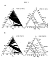
- FIG. 2 is a Fe-Cr-B ternary system isothermal phase diagram that is formed using the database.
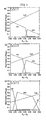
- FIG. 3 illustrates a calculation result of a precipitation driving force change of Cr 2 B according to each component composition on a constituent element (Fe, Cr, B, Si, S, and C) basis of a basic alloy at 1250 °C (pink) and 1000 °C (yellowish green).
- a precipitation driving force is obtained by calculating an amount of a component to adjust in a range from 0 to two times an original amount in a state in which a ratio between other components is fixed.
- the basic alloy When a basic alloy is used for PIM, the basic alloy is sintered for a long time at 1200 °C in a powder injection process, and thus it may be considered that a sintered microstructure has arrived at equilibrium.
- a composition was obtained when the sum (X Fe +X Cr +X B ) of a mole fraction of a major component is maintained at 0.9634 based on a basic alloy of Table 1 as a reference, but values of X Fe and (X Cr +X B ) were adjusted by setting a ratio X Cr /X B of Cr and B to three cases of 1.0 (B ratio increase), 1.6 (basis ratio), and 2.2 (Cr ratio increase).
- FIG. 4 illustrates a fraction of equilibrium phases existing at 1000 °C in the three cases. As the boron ratio increases and as the (X Cr +X B ) value increases, an equilibrium phase fraction of chromium boride (Cr 2 B) increases.
- FIGS. 5 to 7 are graphs illustrating an equilibrium phase fraction according to a temperature of the 9 alloy compositions. Thereby, thermodynamic calculation values of an equilibrium phase fraction of chromium boride (Cr 2 B) at several temperatures may be seen.
- a Cr 2 B fraction is about 43 vol% and the remaining elements are BCC ⁇ -Fe (ferrite) and FCC ⁇ -Fe (austenite).
- BCC ⁇ -Fe ferrite
- FCC ⁇ -Fe austenite
- FIGS. 8 to 10 illustrate SEM microstructures of heat-treated alloys after casting. After heat treatment, because diffusion occurs, a microstructure thereof is considerably different from that of the cast alloy.
- the martensite When martensite is maintained for a long time at a high temperature, the martensite is changed to tempered martensite, i.e., ferrite in which micro-carbides are precipitated, and a form of Cr 2 B is changed from a needle shape or a bar shape to a spherical or oval shape.
- tempered martensite i.e., ferrite in which micro-carbides are precipitated
- a microstructure ( FIG. 9 (f) ) of an alloy of Exemplary Embodiment 6 having the same composition as an alloy of a reference composition is similar to that of a component that is powder injection molded with the basic alloy powder of FIG. 1 . It may be expected that a microstructure of a heat-treated alloy after casting will be similar to a microstructure of a component having passed through a PIM process after making the alloy into powder.
- FIG. 11 illustrates X-ray diffraction analysis results of heat-treated alloys. Because a peak of ⁇ -Fe (ferrite) and Cr 2 B is represented in all alloys, it can be seen that Cr 2 B is distributed within a ferrite base. A precipitated Cr 2 B fraction was measured and is represented in Table 3, and was compared with a Cr 2 B fraction that is obtained from FIGS. 5 to 7 representing an equilibrium phase fraction.
- Hardness of a cast alloy and a heat-treated alloy was measured and is represented in Table 3. Hardness of a cast alloy and a heat-treated alloy is different in the same chemical composition because a microstructure of a cast alloy that is formed with Cr 2 B and martensite is changed after heat treatment.
- martensite is changed to ferrite after heat treatment, and Cr 2 B arrives in an equilibrium state by a diffusion effect by high temperature heat treatment and thus hardness and a fraction of Cr 2 B increases.
- hardness decreases, and as hardness and a fraction of Cr 2 B increases, hardness increases, while hardness of a cast alloy increases or decreases after heat treatment according to a competition relationship between the two.
- Ferrous alloys that are produced in this research may be variously used for producing a PIM component according to a fraction and hardness of Cr 2 B in consideration of similarity of a microstructure ( FIG. 9 (f) ) of an alloy of Exemplary Embodiment 6 and a microstructure ( FIG. 1 ) of a component in which PIM is performed with a basic alloy powder.
- an alloy corresponding thereto for example, alloys of Exemplary Embodiments 1, 5, and 8, may be applied.
- the alloy may have a merit that brittleness decreases and toughness increases, compared with an alloy having high hardness.
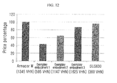
- FIG. 12 is a graph illustrating a price of an alloy element according to a property (hardness reference) that is requested for components.
- a price reference of an alloy element was formed based on an LME daily price (based on July 27, 2010).
- a price of an alloy element that is contained in an alloy that is made in this research is lower than that of a basic alloy, and when hardness decreases, an alloy element price also decreases.
- alloy element may be fully used as a replacement.
- an alloy of this research can be fully applied to a PIM component of various conditions and has an excellent property and advantageous economic efficiency.
- hard Cr 2 B adjusts a Cr 2 B fraction from the present invention in which a PIM alloy that is distributed in a ferrite base is designed, an alloy representing various properties may be successfully produced.
- a Cr 2 B fraction and hardness was estimated from a calculation result of a high temperature equilibrium phase fraction by a thermodynamic calculation, and a ferrous alloy having various Cr 2 B fractions and hardness was produced using this.
- these alloys contain much Cr 2 B that is stable at a high temperature and has excellent corrosion resistance, it is expected that these alloys are much superior to an existing stainless steel PIM component in terms of high temperature property, abrasion resistance, and corrosion resistance, as well as room temperature hardness, and thus there is a new possibility that these alloys can be applied to a structural components that require excellent properties.
- an alloy of Exemplary Embodiment 3 represents hardness of 1600 VHN or more, the alloy may be fully applied even to a PIM component of a tungsten carbide alloy as well as stainless steel.
Landscapes
- Chemical & Material Sciences (AREA)
- Engineering & Computer Science (AREA)
- Mechanical Engineering (AREA)
- Materials Engineering (AREA)
- Metallurgy (AREA)
- Organic Chemistry (AREA)
- Manufacturing & Machinery (AREA)
- Powder Metallurgy (AREA)
Abstract
Description
- The present invention relates to a ferrous alloy, and more particularly, to a ferrous alloy for powder injection molding.
- Powder injection molding (PIM) is new powder metallurgy molding technology in which powder metallurgy technology and an injection molding method, which is mass production technology of a precise plastic component, are coupled.
- A PIM process is a process of producing a component by mixing a micro-powder and a polymer binder to be a subject of flow, injecting the powder and the binder into a mold, removing the binder from the mix, and finally sintering only the powder at a high temperature.
- Continued research and development and expanded application of powder injection molding processes are ongoing because existing component designers and users recognize the merits in that the degree of freedom of component design by a combination of a material used for powder injection molding technology and a shape thereof is high, and diversified application materials and processes having economic efficiency are being developed by research institutions and powder injection molding technology companies.
- That is, three-dimensional precision components may be made entirely of a powder material such as a metal, a ceramic, a carbide, and an intermetallic compound, and even of a processing resistant material or a material that cannot be cast, because mass production is available with few or no post-processes, so powder injection molding technology is appropriate for economically producing high value components.
- Stainless steel that occupies most of a metal powder injection molding market has a property of strength, hardness, abrasion resistance, and corrosion resistance that a final powder injection molding component requires with a change of chemical composition.
- Therefore, a stainless steel powder that is used for powder injection molding variously exists as SUS304L, SUS316L, SUS430, and SUS630, and for martensite-based stainless steel powder injection molding, an additional heat treatment process is necessary.
- Therefore, development of an alloy that can be applied to various powder injection molding components without heat treatment and with economical and various microstructures and properties while fully satisfying a property of a common powder injection molding component is requested.
- The above information disclosed in this Background section is only for enhancement of understanding of the background of the invention and therefore it may contain information that does not form the prior art that is already known in this country to a person of ordinary skill in the art.
- The present invention has been made in an effort to provide a ferrous alloy having advantages of representing superior hardness, abrasion resistance, and corrosion resistance than those of stainless steel that is used for existing powder injection molding and having a low production cost.
- An exemplary embodiment of the present invention provides a ferrous alloy for powder injection molding including: iron (Fe) at 52.59-78.15 wt%, chromium (Cr) at 16.45-37.34 wt%, boron (B) at 3.42-7.76 wt%, silicon (Si) at 1.64-1.92 wt%, sulfur (S) at 0-0.21 wt%, carbon (C) at 0.16-0.18 wt%, and other inevitable impurities.
- A ratio XCr/XB of the chromium (Cr) and boron (B) may be 1.0.
- A sum (XCr+XB) of a composition of the chromium (Cr) and the boron (B) may be 0.30 to 0.60.
- A sum (XFe+XCr+XB) of a composition of the iron (Fe), the chromium (Cr), and the boron (B) may be 0.9635.
- In a microstructure of the ferrous alloy for powder injection molding, chromium boride (Cr2B) may be distributed in a network form within a ferrite base.
- A volume fraction of the chromium boride (Cr2B) may be 51-91 %.
- Hardness of the ferrous alloy for powder injection molding may be 600-1600 VHN.
- Another embodiment of the present invention provides a method of injection molding a ferrous powder, the method including: providing powder of the ferrous alloy for powder injection molding; forming a powder mixture by mixing the powder of the ferrous alloy for powder injection molding and a binder; compression molding the powder mixture; removing the binder by heating the powder mixture; and sintering the powder mixture from which the binder is removed.
- The powder mixture may be formed by mixing the powder of the ferrous alloy for powder injection molding, paraffin wax, tungsten carbide balls, and heptanes in a container and rotating the container.
- Ferrous alloys for powder injection molding according to the present invention form hard Cr2B boride with different volume fractions, thereby greatly improving hardness and abrasion resistance, compared with a conventionally used stainless steel.
- Further, ferrous alloys for powder injection molding according to the present invention are cheaper in alloy price than a commercial stainless steel by lowering a fraction of an alloy element, and by reducing production cost by lowering a sintering temperature and reducing sintering time, the ferrous alloys are superior in price competitiveness.
-
-
FIG. 1 shows scanning electron microscope (SEM) photographs illustrating a microstructure of a ferrous alloy for powder injection molding according to an exemplary embodiment of the present invention. -
FIG. 2 shows Fe-Cr-B ternary system isothermal phase diagrams of a ferrous alloy that is designed according to an exemplary embodiment of the present invention. -
FIG. 3 shows graphs illustrating calculation results of a precipitation driving force change of Cr2B according to each component composition on a constituent element (Fe, Cr, B, Si, S, and C) basis of a basic alloy when designing a ferrous alloy according to an exemplary embodiment of the present invention. -
FIG. 4 shows graphs illustrating a fraction of equilibrium phases existing at 1000 °C according to a ratio of chromium and boron in a ferrous alloy according to an exemplary embodiment of the present invention. -
FIGS. 5 to 7 show graphs illustrating an equilibrium phase fraction according to a temperature of an alloy composition of 9 ferrous alloys that are designed according to an exemplary embodiment of the present invention. -
FIGS. 8 to 10 show SEM photographs of microstructures after ferrous alloys are cast and heated according to an exemplary embodiment of the present invention. -
FIG. 11 illustrates X-ray diffraction analysis results of ferrous alloys according to an exemplary embodiment of the present invention. -
FIG. 12 is a graph illustrating a price of an alloy element according to a property (hardness reference) that is requested for components. - These and other objects of the present application and a method of obtaining them will become more readily apparent from the detailed description given hereinafter together with the accompanying drawings. While the present invention may be embodied in many different forms, specific embodiments of the present invention are shown in drawings and are described herein in detail, with the understanding that the present invention is to be considered as an exemplification of the principles of the invention and is not intended to limit the invention to the specific embodiments illustrated.
- Hereinafter, a ferrous alloy for powder injection molding according to an exemplary embodiment of the present invention will be described with reference to the accompanying drawings. For reference, detailed descriptions of well-known functions and structures incorporated herein may be omitted to avoid obscuring the subject matter of the present invention.
- It is characterized that a ferrous alloy for powder injection molding according to an exemplary embodiment of the present invention includes iron (Fe) at 52.59-78.15 wt%, chromium (Cr) at 16.45-37.34 wt%, boron (B) at 3.42-7.76 wt%, silicon (Si) at 1.64-1.92wt%, sulfur (S) at 0-0.21 wt%, carbon (C) at 0.16-0.18 wt%, and other inevitable impurities.
- A microstructure of the ferrous alloy is characterized in that chromium boride (Cr2B) is distributed in a network form within a ferrite base.
- Because a chromium boride (Cr2B) phase according to the present invention is very hard, a shape and a fraction distribution state of the precipitated chromium boride phase may have a direct influence on entire hardness and abrasion resistance of a specimen.
- Because a chromium boride phase of the ferrous alloy forms a network structure, an entire hardness distribution of the specimen is uniform according to a position, and an applied load in an abrasion environment is distributed to be superior in an abrasion resistance property.
- Further, it is characterized in that a volume fraction of the chromium boride (Cr2B) is 51-91 %.
- It is characterized that hardness of the alloy is 600-1600 VHN.
- In order to satisfy a condition of high hardness and a low cost of the ferrous alloy that is requested in a powder injection molding process, a high hardness property can be obtained using precipitation of chromium boride, which is a compound of Cr and B of a relatively cheap price.
- A composition ratio of chromium (Cr) and boron (B) is fixed to 1:1, and the sum (the sum of a mole fraction) of a composition ratio of chrome (Cr) and boron (B) may be adjusted to 0.30-0.60. In this case, the sum of a composition ratio (the sum of a mole fraction) of iron (Fe), chromium (Cr), and boron (B), which are major components, may be fixed to 0.9634.
- The chromium (Cr) is generally an alloy element that is added to increase hardenability of the alloy and to improve corrosion resistance when quickly cooling, and in the present invention, by bonding to boron (B), the chromium (Cr) is an element that adjusts the chromium boride precipitation fraction.
- When a content of chromium is 16.45 wt% or more, a precipitation fraction of chromium boride is formed to be 50 vol% or more, and thus hardness of about 600 VHN or more, which is a high hardness request value required in a powder injection molding process, can be obtained.
- When a content of chromium exceeds 37.34 wt%, excessive chromium boride is precipitated and thus toughness is deteriorated, so content thereof is limited to 16.45-37.34 wt%.
- A content of boron (B) is determined to be 3.42-7.76 wt% according to such chromium (Cr) content.
- Boron (B) is an element that is added for improving hardenability, and in the present invention, boron (B) is an element that adjusts a chromium boride precipitation fraction by bonding to chromium. When a content of boron is 3.42 wt% or more, a precipitation fraction of chromium boride becomes 50 vol% or more, and thus hardness of about 600 VHN or more, which is a high hardness request value required in a powder injection molding process, can be obtained.
- When a content of boron exceeds 7.76 wt%, excessive chromium boride is precipitated and thus toughness is deteriorated, so content thereof is limited to 3.42-7.76 wt%. A content of chromium is determined to be 16.45-37.34 wt% according to such content of boron.
- In the present invention, silicone (Si) is an element that performs a function of stabilizing a base with ferrite in a sintering press of a powder injection molding process and improving hardenability through solid solution reinforcement. When a content of silicone is 1.64 wt% or less, a solid solution reinforcement and ferrite stabilization effect is slight, and when a content of silicone is 1.92 wt% or more, a solid solution reinforcement effect does not increase in proportion thereto, and so content of silicone is limited to 1.64-1.92 wt%.
- Because sulfur generally forms a non-metallic inclusion and deteriorates properties of an alloy, it is preferable to control sulfur content to be as low as possible, but by adding sulfur up to a limit at which a sulfide (FeS) is not formed, the present invention attempts to obtain a base and chromium boride stabilization effect. Therefore, it is preferable that an upper limit thereof is set to 0.21 wt%.
- Carbon (C) is an element that can efficiently improve hardenability of an alloy, and in order to satisfy hardness that the present invention desires, carbon (C) at 0.16 wt% or more should be contained, and when carbon (C) at 0.18 wt% or more is added, toughness is deteriorated and thus the content of carbon (C) is limited to 0.16-0.18 wt%.
- A method of injection molding a ferrous powder according to another exemplary embodiment of the present invention includes steps of: providing a powder of a ferrous alloy for powder injection molding; forming a powder mixture by mixing the powder of a ferrous alloy for powder injection molding and a binder; compression molding the powder mixture; removing the binder by heating the powder mixture; and sintering the powder mixture from which the binder is removed.
- The powder mixture is formed by mixing a powder of the ferrous alloy for powder injection molding, paraffin wax, tungsten carbide balls, and heptanes in a container and rotating the container.
- Compression molding of the powder mixture may be performed by using a press at a pressure of 100 kgf/cm2 or more after charging the powder mixture into a mold.
- The binder may be removed by raising the temperature of the compression molded powder mixture up to 500 °C at a heating rate of 2 °C/min or more and maintaining the temperature for 1 hour.
- The sintering may be performed by charging the powder mixture from which the binder is removed into a heat treating furnace, heating it to 1175 °C at a heating rate of 3 °C/min or more in a hydrogen atmosphere, and maintaining the temperature for 1 hour.
- The present invention provides a ferrous alloy with high hardness and at a low cost for powder injection molding that may represent various properties by forming chromium boride (Cr2B) of different volume fractions in a ferrite base by reducing a ratio of an alloy element and changing a ratio of chromium (Cr) and boron (B) based on a Fe-43Cr-5.6B-1.8Si-0.2S-0.17C (wt%) alloy.
- Further, a microstructure of alloys according to the present invention may have a structure in which other crystalline particles are distributed in addition to chromium boride (Cr2B) and a ferrite base.
- Hereinafter, the present invention will be described in detail through a description of exemplary embodiments of the present invention and comparative examples. However, the following exemplary embodiments are merely examples for aiding comprehension of the present invention, and the scope of the present invention is not reduced or limited by the following exemplary embodiments.
- Table 1 illustrates a composition of a basic alloy as a reference when designing a ferrous alloy for powder injection molding according to an exemplary embodiment of the present invention.
(Table 1) Fe Cr B Si S C atomic% Bal. 38.15 35.79 22.40 2.77 0.27 0.61 wt% Bal. 49.23 43 5.6 1.8 0.2 0.17 - Table 2 illustrates a composition of an alloy in which a ferrous alloy for powder injection molding according to an exemplary embodiment of the present invention is designed by thermodynamic calculation.
(Table 2) Alloy Ratio Fe Cr B Si S C Exemplary Embodiment 1atomic % 66.34 15.00 15.00 2.77 0.27 0.61 wt% 78.15 16.45 3.42 1.64 0.18 0.16 Exemplary Embodiment 2atomic % 51.34 22.50 22.50 2.77 0.27 0.61 wt% 65.54 26.75 5.56 1.78 0.20 0.17 Exemplary Embodiment 3atomic % 38.15 29.10 29.10 2.77 0.27 0.61 wt% 52.59 37.34 7.76 1.92 0.21 0.18 Exemplary Embodiment 4atomic % 66.34 18.46 11.54 2.77 0.27 0.61 wt% 75.86 19.66 2.55 1.59 0.18 0.15 Exemplary Embodiment 5atomic % 51.34 27.70 17.31 2.77 0.27 0.61 wt% 62.49 31.39 4.08 1.70 0.19 0.16 Exemplary Embodiment 6atomic % 38.15 35.81 22.38 2.77 0.27 0.61 wt% 49.22 43.02 5.59 1.80 0.20 0.17 Exemplary Embodiment 7atomic % 66.34 20.63 9.38 2.77 0.27 0.61 wt% 74.50 21.57 2.04 1.57 0.17 0.15 Exemplary Embodiment 8atomic % 51.34 30.94 14.06 2.77 0.27 0.61 wt% 60.72 34.07 3.22 1.65 0.18 0.16 Exemplary Embodiment 9atomic % 38.15 40.01 18.19 2.77 0.27 0.61 wt% 47.33 46.22 4.37 1.73 0.19 0.16 - A ferrous alloy for powder injection molding was arc melted under an argon (Ar) atmosphere according to a composition of Table 2. An alloy that was used for arc melting included high purity Fe (99.9 wt%), Si (99.99 wt%), and C (99 wt%), as well as previously alloyed FeB (99.2 wt%), FeS (98.5 wt%), and FeCr (98.6 wt%) as a pre-alloy, and was turned over 4-5 times and repeatedly melted so as to uniformize a mother alloy component.
- By suction casting a mother alloy that is produced by arc melting, a bar specimen having a thickness of 5 mm was cast. Because the cast alloy is not in a homogeneous state because of sufficient diffusion, unlike a powder injection molding process product, the cast alloy was heat treated and cooled in a furnace in a similar condition (maintained for 30 min at 1200 °C) to a sintering condition of a powder injection molding process.
- Cast and heat treated alloys were etched with a Viella solution (45 ml glycerol, 15 ml HNO3, and 30 ml HCl) and were observed with a scanning electron microscope (SEM).
- Phases existing within the alloy were analyzed with an X-ray diffraction test method, and a volume fraction of chromium boride (Cr2B) was measured by an image analyzer.
- Entire hardness of the alloy was measured under a load of 300 g by a Vickers hardness device.
- By melting element powders of a ferrous alloy for powder injection molding with a vacuum induction furnace with a 30 kg capacity according to alloy compositions of Table 2, a mother alloy ingot was produced.
- The used alloy included high purity Fe (99.9 wt%), Si (99.99 wt%), and C (99 wt%), and previously alloyed FeB (99.2 wt%), FeS (98.5 wt%), and FeCr (98.6 wt%) as a pre-alloy.
- The ingot was again melted at 1550 °C in an argon (Ar) atmosphere, and was produced as a spherical powder through N2 gas atomization at an injection pressure of 20 bar.
- By classifying this powder, a powder having a size of 25 µm or less was used for powder injection molding.
- In the present invention, in order to easily mix and to reduce volume expansion, paraffin wax was used as a binder. A ferrous powder with a weight of 97 g and 3 g of a binder were mixed and charged into a high-density polyethylene (HDPE) container having a capacity of 300 ml together with 20 ml of tungsten carbide balls, and heptanes were filled to a volume of 250 ml.
- By setting a rotation speed of the container to 45 rpm and rotating for 24 hours, the ferrous powder and the binder were mixed. After a powder mixture was dried at a hot plate at 55 °C, the powder mixture was charged into a circular mold with a diameter of 13 mm and compressed and molded using a press at room temperature with a pressure of 100 kgf/cm2.
- In order to remove the binder from the resultant compact, the temperature of the compact was raised to 500 °C at a heating rate of 2 °C/min, and the compact was maintained and degreased at this temperature for 1 hour. In order to densify the degreased compact, the compact was charged into a heat treating furnace and a temperature thereof was raised up to 1175 °C at a heating rate of 3 °C/min in a hydrogen atmosphere, and the compact was sintered for 1 hour.
- In order to design a changed alloy composition from a basic composition of an alloy, a property determining element of the alloy is determined, and a property (particularly, hardness) of the alloy is closely related to precipitation of chromium boride (Cr2B).
- Accordingly, in order to estimate a chromium boride (Cr2B) forming amount, a thermodynamic calculation was performed. Software that is used for calculation is ThermoCalc, which is a commercial thermodynamic calculation program, and as a thermodynamic database, an upgraded version of TCFE2000 was used.
-
FIG. 2 is a Fe-Cr-B ternary system isothermal phase diagram that is formed using the database. -
FIG. 3 illustrates a calculation result of a precipitation driving force change of Cr2B according to each component composition on a constituent element (Fe, Cr, B, Si, S, and C) basis of a basic alloy at 1250 °C (pink) and 1000 °C (yellowish green). - A precipitation driving force is obtained by calculating an amount of a component to adjust in a range from 0 to two times an original amount in a state in which a ratio between other components is fixed.
- It can be seen from
FIG. 3 that when changing an amount of iron (Fe), chromium (Cr), and boron (B), which are major constituent elements of a basic alloy, a precipitation driving force of chromium boride (Cr2B) is greatly changed. Therefore, when selecting a basic alloy for designing an alloy, iron, chromium, and boron were used as major variables. - When a basic alloy is used for PIM, the basic alloy is sintered for a long time at 1200 °C in a powder injection process, and thus it may be considered that a sintered microstructure has arrived at equilibrium.
- At 1000 °C, which is a temperature that may be thought of as a cooling temperature after arriving at equilibrium, by adjusting a composition of iron, chromium, and boron, an equilibrium phase fraction was calculated.
- A composition was obtained when the sum (XFe+XCr+XB) of a mole fraction of a major component is maintained at 0.9634 based on a basic alloy of Table 1 as a reference, but values of XFe and (XCr+XB) were adjusted by setting a ratio XCr/XB of Cr and B to three cases of 1.0 (B ratio increase), 1.6 (basis ratio), and 2.2 (Cr ratio increase).
-
FIG. 4 illustrates a fraction of equilibrium phases existing at 1000 °C in the three cases. As the boron ratio increases and as the (XCr+XB) value increases, an equilibrium phase fraction of chromium boride (Cr2B) increases. - In a composition ratio of the three cases, by again selecting three cases of (XCr+XB)=0.30, 0.45, and 0.5819, a total of 9 alloy compositions were obtained, and this is represented in Table 2.
- First, at each of compositions in which an XCr/XB ratio is 1.0, 1.6, and 2.2, cases in which the (XCr+XB) sums are 0.30, 0.45, and 0.5819 were divided into
Exemplary Embodiments 1 to 9. - Here,
Exemplary Embodiment 6 of XCr/XB=1.6 and (XCr+XB)=0.5819 is the same as an alloy of Table 1, which is a reference composition. -
FIGS. 5 to 7 are graphs illustrating an equilibrium phase fraction according to a temperature of the 9 alloy compositions. Thereby, thermodynamic calculation values of an equilibrium phase fraction of chromium boride (Cr2B) at several temperatures may be seen. - For example, in an alloy composition of Exemplary Embodiment 1 (XCr/XB=1.0, XCr+XB=0.30), at 1000 °C, a Cr2B fraction is about 43 vol% and the remaining elements are BCC α-Fe (ferrite) and FCC γ-Fe (austenite). When the temperature drops to room temperature, a fraction of Cr2B is maintained, γ-Fe is transformed into α-Fe, and thus it is expected that a room temperature microstructure is formed with Cr2B of 43 vol% and α-Fe of 57 vol%.
- As long time sintering is performed at a high temperature, PIM components arrive at a sufficient equilibrium state, but after melting, because solidification by cooling occurs relatively quickly, a cast alloy may not arrive in an equilibrium state.
- Therefore, in order to obtain a microstructure having arrived in a sufficient equilibrium state, heat treatment corresponding to a sintering process of PIM was applied to a cast alloy.
-
FIGS. 8 to 10 illustrate SEM microstructures of heat-treated alloys after casting. After heat treatment, because diffusion occurs, a microstructure thereof is considerably different from that of the cast alloy. - When martensite is maintained for a long time at a high temperature, the martensite is changed to tempered martensite, i.e., ferrite in which micro-carbides are precipitated, and a form of Cr2B is changed from a needle shape or a bar shape to a spherical or oval shape.
- Like a case of a cast alloy, as (XCr+XB) increases, a tendency that a Cr2B amount increases is represented. A microstructure (
FIG. 9 (f) ) of an alloy ofExemplary Embodiment 6 having the same composition as an alloy of a reference composition is similar to that of a component that is powder injection molded with the basic alloy powder ofFIG. 1 . It may be expected that a microstructure of a heat-treated alloy after casting will be similar to a microstructure of a component having passed through a PIM process after making the alloy into powder. -
FIG. 11 illustrates X-ray diffraction analysis results of heat-treated alloys. Because a peak of α-Fe (ferrite) and Cr2B is represented in all alloys, it can be seen that Cr2B is distributed within a ferrite base. A precipitated Cr2B fraction was measured and is represented in Table 3, and was compared with a Cr2B fraction that is obtained fromFIGS. 5 to 7 representing an equilibrium phase fraction. - Hardness of a cast alloy and a heat-treated alloy was measured and is represented in Table 3. Hardness of a cast alloy and a heat-treated alloy is different in the same chemical composition because a microstructure of a cast alloy that is formed with Cr2B and martensite is changed after heat treatment.
(Table 3) Alloy Volume fraction of chromium boride (vol%) Vickers hardness (VHN) Calculation value After heat treatment After casting After heat treatment Exemplary Embodiment 148 51 1107.5 (±60.8) 595.4 (±37.8) Exemplary Embodiment 271 76 1200.5 (±7.6) 1144.6 (±123.7) Exemplary Embodiment 389 91 1649.6 (±105.1) 1624.7 (±125.2) Exemplary Embodiment 440 46 837.4 (±52.8) 404.4 (±14.6) Exemplary Embodiment 557 59 735.3 (±14.0) 648.9 (±170.7) Exemplary embodiment 671 80 759.5 (±33.4) 1260.5 (±55.5) Exemplary Embodiment 734 42 658.0 (±89.2) 325.7 (±17.7) Exemplary Embodiment 847 47 482.8 (±18.3) 537.0 (±58.2) Exemplary Embodiment 960 66 617.6 (±6.2) 962.5 (±149.2) - In the cast alloy, martensite is changed to ferrite after heat treatment, and Cr2B arrives in an equilibrium state by a diffusion effect by high temperature heat treatment and thus hardness and a fraction of Cr2B increases. After heat treatment, as martensite is changed to ferrite, hardness decreases, and as hardness and a fraction of Cr2B increases, hardness increases, while hardness of a cast alloy increases or decreases after heat treatment according to a competition relationship between the two.
- That is, in an alloy composition having a high Cr2B fraction, an increase effect of hardness and a fraction of Cr2B is larger than a hardness decrease by martensite-ferrite transformation, and thus after heat treatment, hardness increases. However, in an alloy composition having a high ferrite fraction, because a hardness decrease effect by martensite-ferrite transformation is larger than an increase effect of hardness and a fraction of Cr2B, a tendency that hardness decreases after heat treatment is represented.
- Ferrous alloys that are produced in this research may be variously used for producing a PIM component according to a fraction and hardness of Cr2B in consideration of similarity of a microstructure (
FIG. 9 (f) ) of an alloy ofExemplary Embodiment 6 and a microstructure (FIG. 1 ) of a component in which PIM is performed with a basic alloy powder. - As a Cr2B fraction generally increases, hardness increases, but a brittle fracture possibility increases. Therefore, when applying to a PIM component, a high Cr2B fraction and hardness are not always necessary and thus it is preferable to effectively select an alloy having a property that is appropriate for a property that is requested for the component.
- For example, when a hardness condition that is requested for a PIM component is 500-600 VHN, an alloy corresponding thereto, for example, alloys of
Exemplary Embodiments - Further, when a Cr2B fraction increases, an amount of an alloy element increases according to the increased Cr2B fraction, and thus it is preferable to together consider economic efficiency including a price of an alloy element as well as a property that is requested for the PIM component.
-
FIG. 12 is a graph illustrating a price of an alloy element according to a property (hardness reference) that is requested for components. A price reference of an alloy element was formed based on an LME daily price (based on July 27, 2010). - A price of an alloy element that is contained in an alloy that is made in this research is lower than that of a basic alloy, and when hardness decreases, an alloy element price also decreases.
- Further, because a price of an alloy element is lower than that of ferrite-based or martensite-based SUS630 stainless steel (composition: Fe-17Cr-4Ni-4Cu-0.35Nb-0.07C (wt%), hardness: 360 VHN) that is much used for PIM, the alloy element may be fully used as a replacement.
- Therefore, when simultaneously considering a property and economic efficiency that is requested for a PIM component, an alloy of this research can be fully applied to a PIM component of various conditions and has an excellent property and advantageous economic efficiency.
- As described above, as hard Cr2B adjusts a Cr2B fraction from the present invention in which a PIM alloy that is distributed in a ferrite base is designed, an alloy representing various properties may be successfully produced.
- Particularly, a Cr2B fraction and hardness was estimated from a calculation result of a high temperature equilibrium phase fraction by a thermodynamic calculation, and a ferrous alloy having various Cr2B fractions and hardness was produced using this.
- As these alloys contain much Cr2B that is stable at a high temperature and has excellent corrosion resistance, it is expected that these alloys are much superior to an existing stainless steel PIM component in terms of high temperature property, abrasion resistance, and corrosion resistance, as well as room temperature hardness, and thus there is a new possibility that these alloys can be applied to a structural components that require excellent properties.
- Because an alloy of
Exemplary Embodiment 3 represents hardness of 1600 VHN or more, the alloy may be fully applied even to a PIM component of a tungsten carbide alloy as well as stainless steel. - While this invention has been described in connection with what is presently considered to be practical exemplary embodiments, it is to be understood that the invention is not limited to the disclosed embodiments, but, on the contrary, is intended to cover various modifications and equivalent arrangements included within the spirit and scope of the appended claims.
Claims (9)
- A ferrous alloy for powder injection molding, comprising iron (Fe) at 52.59-78.15 wt%, chromium (Cr) at 16.45-37.34 wt%, boron (B) at 3.42-7.76 wt%, silicon (Si) at 1.64-1.92 wt%, sulfur (S) at 0-0.21 wt%, carbon (C) 0.16-0.18 wt%, and other inevitable impurities.
- The ferrous alloy of claim 1, wherein a ratio XCr/XB of the chromium (Cr) and boron (B) is 1.0.
- The ferrous alloy of claim 2, wherein a sum (XCr+XB) of a mole fraction of the chromium (Cr) and the boron (B) is 0.30 to 0.60.
- The ferrous alloy of any one of claims 1 to 3, wherein a sum (XFe+XCr+XB) of a mole fraction of the iron (Fe), the chromium (Cr), and the boron (B) is 0.9635.
- The ferrous alloy of claim 4, wherein in a microstructure of the ferrous alloy for powder injection molding, chromium boride (Cr2B) is distributed in a network form within a ferrite base.
- The ferrous alloy of claim 5, wherein a volume fraction of the chromium boride (Cr2B) is 51-91 %.
- The ferrous alloy of claim 6, wherein hardness of the ferrous alloy for powder injection molding is 600-1600 VHN.
- A method of injection molding a ferrous powder, the method comprising:providing powder of a ferrous alloy for powder injection molding according to any one of claims 1 to 7;forming a powder mixture by mixing the powder of the ferrous alloy for powder injection molding and a binder;compression molding the powder mixture;removing the binder by heating the powder mixture; andsintering the powder mixture from which the binder is removed.
- The method of claim 8, wherein the powder mixture is formed by mixing the powder of the ferrous alloy for powder injection molding according to any one of claims 1 to 8, paraffin wax, tungsten carbide balls, and heptanes in a container and rotating the container.
Applications Claiming Priority (2)
| Application Number | Priority Date | Filing Date | Title |
|---|---|---|---|
| KR1020110108028A KR101350944B1 (en) | 2011-10-21 | 2011-10-21 | Ferrous-alloys for powder injection molding |
| PCT/KR2012/003071 WO2013058453A1 (en) | 2011-10-21 | 2012-04-20 | Iron-based alloy for powder injection molding |
Publications (2)
| Publication Number | Publication Date |
|---|---|
| EP2770074A1 true EP2770074A1 (en) | 2014-08-27 |
| EP2770074A4 EP2770074A4 (en) | 2016-04-20 |
Family
ID=48141076
Family Applications (1)
| Application Number | Title | Priority Date | Filing Date |
|---|---|---|---|
| EP12841059.4A Withdrawn EP2770074A4 (en) | 2011-10-21 | 2012-04-20 | IRON ALLOY FOR INJECTION MOLDING OF POWDER |
Country Status (6)
| Country | Link |
|---|---|
| US (1) | US20140227124A1 (en) |
| EP (1) | EP2770074A4 (en) |
| JP (1) | JP5819001B2 (en) |
| KR (1) | KR101350944B1 (en) |
| CN (1) | CN103890210B (en) |
| WO (1) | WO2013058453A1 (en) |
Cited By (1)
| Publication number | Priority date | Publication date | Assignee | Title |
|---|---|---|---|---|
| CZ305979B6 (en) * | 2014-12-05 | 2016-06-01 | Česká zemědělská univerzita v Praze | Bimetallic metallic material |
Families Citing this family (10)
| Publication number | Priority date | Publication date | Assignee | Title |
|---|---|---|---|---|
| KR101405845B1 (en) * | 2012-08-10 | 2014-06-11 | 기아자동차주식회사 | Method for manufacturing of valve train parts using with metal powder injection molding |
| KR20140048428A (en) * | 2012-10-15 | 2014-04-24 | 현대자동차주식회사 | Method for manufacturing of control finger using with metal powder injection molding |
| US9115958B2 (en) | 2013-03-15 | 2015-08-25 | Leupold & Stevens, Inc. | Dual field optical aiming system for projectile weapons |
| EP3156155A1 (en) * | 2015-10-15 | 2017-04-19 | Höganäs AB (publ) | Iron based powders for powder injection molding |
| JP6735106B2 (en) * | 2016-01-29 | 2020-08-05 | 株式会社ダイヤメット | Co-free heat-resistant sintered material excellent in high-temperature wear resistance and high-temperature strength, and method for producing the same |
| KR102130490B1 (en) * | 2018-12-18 | 2020-07-06 | 주식회사 엔이피 | Fe-based Metal Parts Producing Method Used For Automobile Steering Wheel |
| CN111001813B (en) * | 2019-12-28 | 2022-02-18 | 合肥波林新材料股份有限公司 | High-antifriction iron-based vulcanized powder metallurgy oil-retaining bearing material and preparation method and application thereof |
| CN111304555B (en) * | 2020-03-31 | 2022-02-01 | 广东省科学院新材料研究所 | In-situ endogenously precipitated ceramic particle reinforced Cr-Mn-Ni-C-N austenitic heat-resistant steel and preparation method and application thereof |
| CN111560555A (en) * | 2020-05-18 | 2020-08-21 | 上海红重机械装备有限公司 | Manufacturing process of steel structure lifting system |
| JP7812670B2 (en) * | 2022-01-24 | 2026-02-10 | 山陽特殊製鋼株式会社 | Fe-based alloy for sintering |
Family Cites Families (9)
| Publication number | Priority date | Publication date | Assignee | Title |
|---|---|---|---|---|
| US4822415A (en) * | 1985-11-22 | 1989-04-18 | Perkin-Elmer Corporation | Thermal spray iron alloy powder containing molybdenum, copper and boron |
| US5643531A (en) * | 1989-12-12 | 1997-07-01 | Samsung Heavy Industry Co., Ltd. | Ferrous alloy composition and manufacture and coating methods of mechanical products using the same |
| KR960041395A (en) * | 1995-05-31 | 1996-12-19 | 유상부 | Iron base alloy with excellent corrosion resistance and abrasion resistance, and a method for producing a corrosion resistant wear member using the same |
| JPH10317009A (en) * | 1997-05-20 | 1998-12-02 | Sumitomo Metal Mining Co Ltd | Manufacturing method of stainless sintered body |
| CH694401A5 (en) * | 1999-05-26 | 2004-12-31 | Basf Ag | Low-nickel, low-molybdenum, biocompatible, non-allergenic, corrosion-resistant austenitic steel. |
| JP3988971B2 (en) | 2000-02-21 | 2007-10-10 | 日本ピストンリング株式会社 | Sintered member |
| US20050163645A1 (en) * | 2004-01-28 | 2005-07-28 | Borgwarner Inc. | Method to make sinter-hardened powder metal parts with complex shapes |
| KR100650409B1 (en) * | 2004-12-17 | 2006-11-27 | (주)엠티아이지 | Manufacturing method of complex shape material using powder injection molding and material produced accordingly |
| KR100768700B1 (en) | 2006-06-28 | 2007-10-19 | 학교법인 포항공과대학교 | Manufacturing method and alloy parts of alloy parts using metal injection molding |
-
2011
- 2011-10-21 KR KR1020110108028A patent/KR101350944B1/en active Active
-
2012
- 2012-04-20 CN CN201280051137.9A patent/CN103890210B/en not_active Expired - Fee Related
- 2012-04-20 JP JP2014536968A patent/JP5819001B2/en not_active Expired - Fee Related
- 2012-04-20 WO PCT/KR2012/003071 patent/WO2013058453A1/en not_active Ceased
- 2012-04-20 EP EP12841059.4A patent/EP2770074A4/en not_active Withdrawn
- 2012-04-20 US US14/349,122 patent/US20140227124A1/en not_active Abandoned
Cited By (1)
| Publication number | Priority date | Publication date | Assignee | Title |
|---|---|---|---|---|
| CZ305979B6 (en) * | 2014-12-05 | 2016-06-01 | Česká zemědělská univerzita v Praze | Bimetallic metallic material |
Also Published As
| Publication number | Publication date |
|---|---|
| US20140227124A1 (en) | 2014-08-14 |
| KR101350944B1 (en) | 2014-01-16 |
| CN103890210A (en) | 2014-06-25 |
| CN103890210B (en) | 2016-05-04 |
| JP5819001B2 (en) | 2015-11-18 |
| JP2014534344A (en) | 2014-12-18 |
| KR20130043871A (en) | 2013-05-02 |
| EP2770074A4 (en) | 2016-04-20 |
| WO2013058453A1 (en) | 2013-04-25 |
Similar Documents
| Publication | Publication Date | Title |
|---|---|---|
| US20140227124A1 (en) | Iron-based alloy for powder injection molding | |
| JP5902091B2 (en) | Nitrogen-containing low nickel sintered stainless steel | |
| CN103282527B (en) | For the iron-based powder of powder injection forming | |
| JP2687125B2 (en) | Sintered metal compact used for engine valve parts and its manufacturing method. | |
| EP0480495B1 (en) | Sintered ferrous-based material | |
| JP2010090470A (en) | Iron-based sintered alloy and method for producing the same | |
| Kumaran et al. | A novel and sustainable method to develop non-equiatomic CoCrFeNiMox high entropy alloys via spark plasma sintering using commercial commodity powders and evaluation of its mechanical behaviour | |
| CN108367356A (en) | Iron-Based Powders for Powder Injection Molding | |
| WO2008002001A1 (en) | Fabrication method of alloy parts by metal injection molding and the alloy parts | |
| JPS5867842A (en) | Hard sintered alloy | |
| Do et al. | Effects of Cr and B contents on volume fraction of (Cr, Fe) 2B and hardness in Fe-based alloys used for powder injection molding | |
| KR101736108B1 (en) | Casting manufacturing method of cermet and cermet manufactured thereby | |
| US20170260609A1 (en) | Precipitate strengthened nanostructured ferritic alloy and method of forming | |
| JP5114233B2 (en) | Iron-based sintered alloy and method for producing the same | |
| JPH10504353A (en) | Iron-based powder containing chromium, molybdenum and manganese | |
| JP4371003B2 (en) | Alloy steel powder for powder metallurgy | |
| KR101522879B1 (en) | Chemical composition and fabrication method of hard fe-based materials with amorphous phases | |
| JPH0751721B2 (en) | Low alloy iron powder for sintering | |
| JPH0347951A (en) | Iron-base sintered alloy for valve seat | |
| WO2025182224A1 (en) | Sintered component and method for manufacturing sintered component | |
| JPH06172804A (en) | Injection-moldeing ferrous alloy powder | |
| CN108570614A (en) | A kind of molybdenum element segregation toughening high hardness alloy and its casting method | |
| CN108570615A (en) | A kind of refractory metal segregation toughening high hardness alloy and its casting method | |
| JP2007100115A (en) | Alloy steel powder for powder metallurgy | |
| JPH0533299B2 (en) |
Legal Events
| Date | Code | Title | Description |
|---|---|---|---|
| PUAI | Public reference made under article 153(3) epc to a published international application that has entered the european phase |
Free format text: ORIGINAL CODE: 0009012 |
|
| 17P | Request for examination filed |
Effective date: 20140414 |
|
| AK | Designated contracting states |
Kind code of ref document: A1 Designated state(s): AL AT BE BG CH CY CZ DE DK EE ES FI FR GB GR HR HU IE IS IT LI LT LU LV MC MK MT NL NO PL PT RO RS SE SI SK SM TR |
|
| DAX | Request for extension of the european patent (deleted) | ||
| RA4 | Supplementary search report drawn up and despatched (corrected) |
Effective date: 20160318 |
|
| RIC1 | Information provided on ipc code assigned before grant |
Ipc: C22C 38/42 20060101ALI20160314BHEP Ipc: B22F 3/12 20060101ALI20160314BHEP Ipc: C22C 38/60 20060101ALI20160314BHEP Ipc: C22C 38/32 20060101ALI20160314BHEP Ipc: C22C 38/34 20060101ALI20160314BHEP Ipc: C22C 33/02 20060101ALI20160314BHEP Ipc: C22C 38/00 20060101AFI20160314BHEP Ipc: C22C 38/48 20060101ALI20160314BHEP Ipc: B22F 3/22 20060101ALI20160314BHEP Ipc: C22C 30/00 20060101ALI20160314BHEP |
|
| 17Q | First examination report despatched |
Effective date: 20170607 |
|
| STAA | Information on the status of an ep patent application or granted ep patent |
Free format text: STATUS: THE APPLICATION IS DEEMED TO BE WITHDRAWN |
|
| 18D | Application deemed to be withdrawn |
Effective date: 20171018 |