EP2769823A2 - Verfahren zur Nutzung der in einem Extrusionsprozess abgegebenen Wärmemenge - Google Patents
Verfahren zur Nutzung der in einem Extrusionsprozess abgegebenen Wärmemenge Download PDFInfo
- Publication number
- EP2769823A2 EP2769823A2 EP14155563.1A EP14155563A EP2769823A2 EP 2769823 A2 EP2769823 A2 EP 2769823A2 EP 14155563 A EP14155563 A EP 14155563A EP 2769823 A2 EP2769823 A2 EP 2769823A2
- Authority
- EP
- European Patent Office
- Prior art keywords
- fluid
- temperature
- heat
- process chain
- amount
- Prior art date
- Legal status (The legal status is an assumption and is not a legal conclusion. Google has not performed a legal analysis and makes no representation as to the accuracy of the status listed.)
- Granted
Links
- 238000000034 method Methods 0.000 title claims abstract description 64
- 230000008569 process Effects 0.000 title claims abstract description 47
- 238000001125 extrusion Methods 0.000 title claims abstract description 24
- 239000012530 fluid Substances 0.000 claims abstract description 81
- 238000001816 cooling Methods 0.000 claims abstract description 23
- 238000002156 mixing Methods 0.000 claims abstract description 3
- 230000001105 regulatory effect Effects 0.000 claims description 6
- 230000001960 triggered effect Effects 0.000 claims description 5
- 238000005259 measurement Methods 0.000 claims description 3
- 239000003570 air Substances 0.000 description 41
- 239000004033 plastic Substances 0.000 description 14
- 229920003023 plastic Polymers 0.000 description 14
- 238000009529 body temperature measurement Methods 0.000 description 3
- 239000002826 coolant Substances 0.000 description 3
- 238000005516 engineering process Methods 0.000 description 3
- 239000012080 ambient air Substances 0.000 description 2
- 238000004519 manufacturing process Methods 0.000 description 2
- 238000007493 shaping process Methods 0.000 description 2
- 239000000243 solution Substances 0.000 description 2
- 229920000426 Microplastic Polymers 0.000 description 1
- 230000004913 activation Effects 0.000 description 1
- 239000000654 additive Substances 0.000 description 1
- 230000008901 benefit Effects 0.000 description 1
- 238000010924 continuous production Methods 0.000 description 1
- 230000001419 dependent effect Effects 0.000 description 1
- 238000011161 development Methods 0.000 description 1
- 230000000694 effects Effects 0.000 description 1
- 230000007613 environmental effect Effects 0.000 description 1
- 239000003344 environmental pollutant Substances 0.000 description 1
- 239000004744 fabric Substances 0.000 description 1
- 239000008187 granular material Substances 0.000 description 1
- 238000010438 heat treatment Methods 0.000 description 1
- 230000004941 influx Effects 0.000 description 1
- 238000002347 injection Methods 0.000 description 1
- 239000007924 injection Substances 0.000 description 1
- 238000002844 melting Methods 0.000 description 1
- 230000008018 melting Effects 0.000 description 1
- 230000000116 mitigating effect Effects 0.000 description 1
- 239000000203 mixture Substances 0.000 description 1
- 239000002991 molded plastic Substances 0.000 description 1
- 238000000465 moulding Methods 0.000 description 1
- 230000003287 optical effect Effects 0.000 description 1
- 231100000719 pollutant Toxicity 0.000 description 1
- 230000000630 rising effect Effects 0.000 description 1
- 239000000126 substance Substances 0.000 description 1
- 239000012815 thermoplastic material Substances 0.000 description 1
- 238000009757 thermoplastic moulding Methods 0.000 description 1
- 238000012549 training Methods 0.000 description 1
- XLYOFNOQVPJJNP-UHFFFAOYSA-N water Substances O XLYOFNOQVPJJNP-UHFFFAOYSA-N 0.000 description 1
Images

Classifications
-
- B—PERFORMING OPERATIONS; TRANSPORTING
- B29—WORKING OF PLASTICS; WORKING OF SUBSTANCES IN A PLASTIC STATE IN GENERAL
- B29C—SHAPING OR JOINING OF PLASTICS; SHAPING OF MATERIAL IN A PLASTIC STATE, NOT OTHERWISE PROVIDED FOR; AFTER-TREATMENT OF THE SHAPED PRODUCTS, e.g. REPAIRING
- B29C48/00—Extrusion moulding, i.e. expressing the moulding material through a die or nozzle which imparts the desired form; Apparatus therefor
- B29C48/25—Component parts, details or accessories; Auxiliary operations
- B29C48/88—Thermal treatment of the stream of extruded material, e.g. cooling
- B29C48/90—Thermal treatment of the stream of extruded material, e.g. cooling with calibration or sizing, i.e. combined with fixing or setting of the final dimensions of the extruded article
- B29C48/908—Thermal treatment of the stream of extruded material, e.g. cooling with calibration or sizing, i.e. combined with fixing or setting of the final dimensions of the extruded article characterised by calibrator surface, e.g. structure or holes for lubrication, cooling or venting
-
- B—PERFORMING OPERATIONS; TRANSPORTING
- B29—WORKING OF PLASTICS; WORKING OF SUBSTANCES IN A PLASTIC STATE IN GENERAL
- B29C—SHAPING OR JOINING OF PLASTICS; SHAPING OF MATERIAL IN A PLASTIC STATE, NOT OTHERWISE PROVIDED FOR; AFTER-TREATMENT OF THE SHAPED PRODUCTS, e.g. REPAIRING
- B29C48/00—Extrusion moulding, i.e. expressing the moulding material through a die or nozzle which imparts the desired form; Apparatus therefor
- B29C48/03—Extrusion moulding, i.e. expressing the moulding material through a die or nozzle which imparts the desired form; Apparatus therefor characterised by the shape of the extruded material at extrusion
- B29C48/09—Articles with cross-sections having partially or fully enclosed cavities, e.g. pipes or channels
-
- B—PERFORMING OPERATIONS; TRANSPORTING
- B29—WORKING OF PLASTICS; WORKING OF SUBSTANCES IN A PLASTIC STATE IN GENERAL
- B29C—SHAPING OR JOINING OF PLASTICS; SHAPING OF MATERIAL IN A PLASTIC STATE, NOT OTHERWISE PROVIDED FOR; AFTER-TREATMENT OF THE SHAPED PRODUCTS, e.g. REPAIRING
- B29C48/00—Extrusion moulding, i.e. expressing the moulding material through a die or nozzle which imparts the desired form; Apparatus therefor
- B29C48/25—Component parts, details or accessories; Auxiliary operations
- B29C48/275—Recovery or reuse of energy or materials
- B29C48/276—Recovery or reuse of energy or materials of energy
-
- B—PERFORMING OPERATIONS; TRANSPORTING
- B29—WORKING OF PLASTICS; WORKING OF SUBSTANCES IN A PLASTIC STATE IN GENERAL
- B29C—SHAPING OR JOINING OF PLASTICS; SHAPING OF MATERIAL IN A PLASTIC STATE, NOT OTHERWISE PROVIDED FOR; AFTER-TREATMENT OF THE SHAPED PRODUCTS, e.g. REPAIRING
- B29C48/00—Extrusion moulding, i.e. expressing the moulding material through a die or nozzle which imparts the desired form; Apparatus therefor
- B29C48/25—Component parts, details or accessories; Auxiliary operations
- B29C48/78—Thermal treatment of the extrusion moulding material or of preformed parts or layers, e.g. by heating or cooling
- B29C48/793—Thermal treatment of the extrusion moulding material or of preformed parts or layers, e.g. by heating or cooling upstream of the plasticising zone, e.g. heating in the hopper
-
- B—PERFORMING OPERATIONS; TRANSPORTING
- B29—WORKING OF PLASTICS; WORKING OF SUBSTANCES IN A PLASTIC STATE IN GENERAL
- B29C—SHAPING OR JOINING OF PLASTICS; SHAPING OF MATERIAL IN A PLASTIC STATE, NOT OTHERWISE PROVIDED FOR; AFTER-TREATMENT OF THE SHAPED PRODUCTS, e.g. REPAIRING
- B29C48/00—Extrusion moulding, i.e. expressing the moulding material through a die or nozzle which imparts the desired form; Apparatus therefor
- B29C48/25—Component parts, details or accessories; Auxiliary operations
- B29C48/78—Thermal treatment of the extrusion moulding material or of preformed parts or layers, e.g. by heating or cooling
- B29C48/80—Thermal treatment of the extrusion moulding material or of preformed parts or layers, e.g. by heating or cooling at the plasticising zone, e.g. by heating cylinders
- B29C48/82—Cooling
-
- B—PERFORMING OPERATIONS; TRANSPORTING
- B29—WORKING OF PLASTICS; WORKING OF SUBSTANCES IN A PLASTIC STATE IN GENERAL
- B29C—SHAPING OR JOINING OF PLASTICS; SHAPING OF MATERIAL IN A PLASTIC STATE, NOT OTHERWISE PROVIDED FOR; AFTER-TREATMENT OF THE SHAPED PRODUCTS, e.g. REPAIRING
- B29C48/00—Extrusion moulding, i.e. expressing the moulding material through a die or nozzle which imparts the desired form; Apparatus therefor
- B29C48/25—Component parts, details or accessories; Auxiliary operations
- B29C48/78—Thermal treatment of the extrusion moulding material or of preformed parts or layers, e.g. by heating or cooling
- B29C48/80—Thermal treatment of the extrusion moulding material or of preformed parts or layers, e.g. by heating or cooling at the plasticising zone, e.g. by heating cylinders
- B29C48/83—Heating or cooling the cylinders
- B29C48/834—Cooling
-
- B—PERFORMING OPERATIONS; TRANSPORTING
- B29—WORKING OF PLASTICS; WORKING OF SUBSTANCES IN A PLASTIC STATE IN GENERAL
- B29C—SHAPING OR JOINING OF PLASTICS; SHAPING OF MATERIAL IN A PLASTIC STATE, NOT OTHERWISE PROVIDED FOR; AFTER-TREATMENT OF THE SHAPED PRODUCTS, e.g. REPAIRING
- B29C48/00—Extrusion moulding, i.e. expressing the moulding material through a die or nozzle which imparts the desired form; Apparatus therefor
- B29C48/25—Component parts, details or accessories; Auxiliary operations
- B29C48/88—Thermal treatment of the stream of extruded material, e.g. cooling
- B29C48/911—Cooling
- B29C48/9115—Cooling of hollow articles
-
- B—PERFORMING OPERATIONS; TRANSPORTING
- B29—WORKING OF PLASTICS; WORKING OF SUBSTANCES IN A PLASTIC STATE IN GENERAL
- B29C—SHAPING OR JOINING OF PLASTICS; SHAPING OF MATERIAL IN A PLASTIC STATE, NOT OTHERWISE PROVIDED FOR; AFTER-TREATMENT OF THE SHAPED PRODUCTS, e.g. REPAIRING
- B29C48/00—Extrusion moulding, i.e. expressing the moulding material through a die or nozzle which imparts the desired form; Apparatus therefor
- B29C48/25—Component parts, details or accessories; Auxiliary operations
- B29C48/92—Measuring, controlling or regulating
-
- B—PERFORMING OPERATIONS; TRANSPORTING
- B29—WORKING OF PLASTICS; WORKING OF SUBSTANCES IN A PLASTIC STATE IN GENERAL
- B29C—SHAPING OR JOINING OF PLASTICS; SHAPING OF MATERIAL IN A PLASTIC STATE, NOT OTHERWISE PROVIDED FOR; AFTER-TREATMENT OF THE SHAPED PRODUCTS, e.g. REPAIRING
- B29C2948/00—Indexing scheme relating to extrusion moulding
- B29C2948/92—Measuring, controlling or regulating
- B29C2948/92504—Controlled parameter
- B29C2948/9258—Velocity
- B29C2948/926—Flow or feed rate
-
- B—PERFORMING OPERATIONS; TRANSPORTING
- B29—WORKING OF PLASTICS; WORKING OF SUBSTANCES IN A PLASTIC STATE IN GENERAL
- B29C—SHAPING OR JOINING OF PLASTICS; SHAPING OF MATERIAL IN A PLASTIC STATE, NOT OTHERWISE PROVIDED FOR; AFTER-TREATMENT OF THE SHAPED PRODUCTS, e.g. REPAIRING
- B29C2948/00—Indexing scheme relating to extrusion moulding
- B29C2948/92—Measuring, controlling or regulating
- B29C2948/92504—Controlled parameter
- B29C2948/92704—Temperature
-
- B—PERFORMING OPERATIONS; TRANSPORTING
- B29—WORKING OF PLASTICS; WORKING OF SUBSTANCES IN A PLASTIC STATE IN GENERAL
- B29C—SHAPING OR JOINING OF PLASTICS; SHAPING OF MATERIAL IN A PLASTIC STATE, NOT OTHERWISE PROVIDED FOR; AFTER-TREATMENT OF THE SHAPED PRODUCTS, e.g. REPAIRING
- B29C2948/00—Indexing scheme relating to extrusion moulding
- B29C2948/92—Measuring, controlling or regulating
- B29C2948/92819—Location or phase of control
- B29C2948/92971—Fluids, e.g. for temperature control or of environment
-
- B—PERFORMING OPERATIONS; TRANSPORTING
- B29—WORKING OF PLASTICS; WORKING OF SUBSTANCES IN A PLASTIC STATE IN GENERAL
- B29C—SHAPING OR JOINING OF PLASTICS; SHAPING OF MATERIAL IN A PLASTIC STATE, NOT OTHERWISE PROVIDED FOR; AFTER-TREATMENT OF THE SHAPED PRODUCTS, e.g. REPAIRING
- B29C48/00—Extrusion moulding, i.e. expressing the moulding material through a die or nozzle which imparts the desired form; Apparatus therefor
- B29C48/25—Component parts, details or accessories; Auxiliary operations
- B29C48/88—Thermal treatment of the stream of extruded material, e.g. cooling
- B29C48/885—External treatment, e.g. by using air rings for cooling tubular films
-
- B—PERFORMING OPERATIONS; TRANSPORTING
- B29—WORKING OF PLASTICS; WORKING OF SUBSTANCES IN A PLASTIC STATE IN GENERAL
- B29C—SHAPING OR JOINING OF PLASTICS; SHAPING OF MATERIAL IN A PLASTIC STATE, NOT OTHERWISE PROVIDED FOR; AFTER-TREATMENT OF THE SHAPED PRODUCTS, e.g. REPAIRING
- B29C48/00—Extrusion moulding, i.e. expressing the moulding material through a die or nozzle which imparts the desired form; Apparatus therefor
- B29C48/25—Component parts, details or accessories; Auxiliary operations
- B29C48/88—Thermal treatment of the stream of extruded material, e.g. cooling
- B29C48/911—Cooling
- B29C48/9115—Cooling of hollow articles
- B29C48/912—Cooling of hollow articles of tubular films
-
- Y—GENERAL TAGGING OF NEW TECHNOLOGICAL DEVELOPMENTS; GENERAL TAGGING OF CROSS-SECTIONAL TECHNOLOGIES SPANNING OVER SEVERAL SECTIONS OF THE IPC; TECHNICAL SUBJECTS COVERED BY FORMER USPC CROSS-REFERENCE ART COLLECTIONS [XRACs] AND DIGESTS
- Y02—TECHNOLOGIES OR APPLICATIONS FOR MITIGATION OR ADAPTATION AGAINST CLIMATE CHANGE
- Y02P—CLIMATE CHANGE MITIGATION TECHNOLOGIES IN THE PRODUCTION OR PROCESSING OF GOODS
- Y02P70/00—Climate change mitigation technologies in the production process for final industrial or consumer products
- Y02P70/10—Greenhouse gas [GHG] capture, material saving, heat recovery or other energy efficient measures, e.g. motor control, characterised by manufacturing processes, e.g. for rolling metal or metal working
Definitions
- the invention relates to a method for utilizing the amount of heat emitted by the extrudate during an extrusion process during the cooling process, wherein a fluid, in particular air, is guided against the extrusion direction along the extrudate and / or through the tool, at least part of the heat from the extrudate and / or or the tool is transferred to the fluid, the heated fluid from a first portion of the process chain, comprising at least one tool, a calibration and cooling device and a trigger device, via a connection region, preferably consisting of at least one connecting tube, a second portion of the process chain, comprising at least one suction device, is supplied.
- thermoplastic molding composition in the desired final shape of the plastic part. This can be done on the one hand by injection into a suitable mold or in a continuous process in an extrusion process. In both cases, it is necessary to first supply heat to the plastic granules in order to melt it, and then, after shaping, to extract heat from the molded plastic part so that it remains dimensionally stable.
- the DE 10 2007 050 949 A1 is already dealing with this topic and proposes a method for energy use in cooling extrusion profiles, in which energy is supplied in the form of heat for melting the plastic and after molding at least in the devices tool, calibration and cooling bath heat so long back to the plastic is withdrawn until it is self-supporting.
- a cooling medium for cooling flows through the extrusion line counter to the direction of extrusion, wherein the medium used for cooling is passed from one device to the next. It is therefore already here proposed a kind of cycle in which the coolant used is further promoted from one device to the next, and thus the cooling medium from station to station is warmer, which can then be used for example for heating or for hot water.
- the energy used can be harnessed for further processes.
- the DE 10 2010 064 412 A1 already goes a step further and proposes a method for maintaining the output of an extrudate to a fluid heat flow.
- a fluid primarily air
- the essence of the invention is to optimize the fluid flow so that the largest possible amount of heat is removed from the plastic, and this is the same throughout the entire length of extrudate as possible at all points, so that an optimal cooling process can be achieved.
- the object of the invention is to make the amount of heat released in an extrusion process as 100 percent as possible for a further process, without the energy source to which these Amount of heat was supplied in the subsequent process chain can cause damage, which could occur, for example, at too high end temperatures of the energy source.
- the solution of the problem is characterized in connection with the preamble of claim 1, characterized in that the temperature of the fluid does not exceed a predetermined maximum value, wherein a third fluid can be admixed with the heated fluid in the connecting region to the actual temperature of the mixed fluid at least among the predetermined maximum value to before it is fed to the second section of the process chain.
- This proposed method ensures that the heated fluid - here primarily air is used - always so much foreign fluid - this will be usually ambient air-the heated air can be mixed, that this can never reach a temperature which could cause damage to components of the subsequent process. Namely, it is possible, e.g. First, to clean this drawn through the extrudate air in a filter, as the air was possibly supplied by the plastic mass escaping pollutants that you do not necessarily want to give back directly to the environment. Furthermore, could be included in the heated air additives that could tend to auto-ignition above a certain temperature range. For this reason, it must be ensured that the heated air does not reach a temperature range at which these described substances, e.g. react in the mentioned filter with the filter fabric and cause damage.
- measuring the fluid temperature before the fluid is supplied to the second subarea also has the advantage that, in addition, if the fluid temperature at the outlet of the first subarea is measured, the amount of external air to be supplied can be controlled or regulated.
- this temperature measurement is namely known, with which temperature the fluid leaves the first portion and, due to the predetermined maximum temperature by means of known control technology, determinable how large the amount of external air required is. It is also advantageous to take the temperature of the external air, because the warmer the external air itself, the more external air must of course be added to the heated fluid. Depending on the application, it may be necessary to pre-cool this external air via suitable means in order to achieve the desired cooling of the heated fluid can.
- the control of the external air supply can be realized via an adjustable shut-off valve, but also via simple flaps. It is readily conceivable to determine the amount of external air via a manually displaceable flap, which can be opened, for example, to 25, 50 or 100 percent. Of course, the amount of external air can also be influenced by the size of the respective opening or openings. In any case, it is ensured by the amount of external air that the fluid temperature at the entrance of the second portion is kept below the maximum temperature.
- the temperature measurement of the fluid is connected to the system control, so that when reaching a limit value of the temperature, ie a limit temperature, in any form Alarm device is controlled.
- a limit value of the temperature ie a limit temperature
- this limit temperature, from which an alarm is triggered stored in the system. This may be a predetermined value below the maximum temperature or a value determinable by a factor of the maximum value.
- the suction device can always keep the amount of heat from the first partial area constant despite the inflow of external air via a corresponding control and / or regulating technology.
- This regulation of the flow velocity of the fluid ensures that the amount of heat released in the first subarea of the process chain, that is, the amount of heat emitted by the extrudate and / or tool, largely corresponds to the amount of heat released at the end of the process chain.
- the temperature of the energy carrier in this case the air or the fluid which is supplied to another process for further use, may be lower than the fluid temperature, which has the fluid flowing through it during the cooling of the extrudate and the tool .
- the amount of heat that has been transferred to the energy source in the cooling process from the extrudate and / or the tool largely identical to the amount of heat that is passed to the subsequent process.
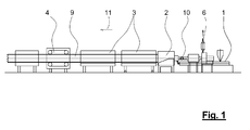
- FIG. 1 shows a typical extrusion line, as used today for profile extrusion, whether for the production of window profiles or pipes. It shows an extruder 1, in which plastic is melted, and is conveyed continuously for shaping into the extrusion die 2. This is followed by a calibration and cooling device 3, depending on the profile more cooling stations can be used. After the cooling stations, a trigger device 4 connects. In order to cut off the endless profiles 9 to the desired length, a separating device is then usually arranged (not shown). Contrary to the extrusion direction 11, a fluid is drawn by means of a suction device 8 through the extrudate 9, in this case a plastic tube, and through the tool 2 and fed via a connecting tube to an air outlet 6.
- FIG. 2 shows a portion of this extrusion line. Recognizable again is the extruder 1, which transfers the molten plastic mass to a tool 2, in which a plastic tube is formed. The dimensional stability is created in the calibration and cooling station 3. Further cooling stations can follow until the dimensionally stable tube is conveyed via the trigger 4 in the direction of extrusion 11. By means of a dot-dash line, a first portion 12 of this process chain is marked. This subregion comprises at least the tool 2, the cooling and calibration station 3 and the trigger 4.
- a fluid 15 in which Usually ambient air, along the wall, this may be the inner or outer wall, the plastic pipe promoted, wherein the air flow can flow around the tool 2 or portions of the tool 2 also.
- the air flow 15 energy is transferred in the form of heat.
- This amount of heat is symbolically indicated by a thick arrow as Q ⁇ ab .
- This amount of heat Q ab is a second partial region 14, indicated here by a dashed black box passed.
- a connecting region 13 is located between the first subregion 12 and the second subregion 14. Within this connecting region 13, a foreign fluid 16 can be added to the fluid 15 and, if an external fluid 16 has been admixed, guided into the second subregion 14 as mixed fluid 21.
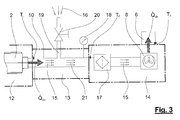
- FIG. 3 joins in, so to speak FIG. 2 at.
- the portion 12 with the tool 2 is slightly schematically indicated, the thick arrow symbolizes again the output from the first portion 12 heat quantity q.
- the fluid 15 flows through the connecting region 13 in a connecting tube 10.
- the connecting tube 10 communicates with an external air channel 19, via which external air 16 can be sucked.
- the amount of external air 16 is controlled by a shut-off valve 20.
- the amount can be controlled or regulated from simple manual sliders to complex plant controls.
- a bore which allows the permanent influx of ambient air (foreign fluid). If the possible process window with all the resulting parameters is known, this is a simple solution, it could even be the temperature measurement is unnecessary.
- the temperature of the mixing fluid 21 at the end of the connecting region 13 and thus at the input of the partial region 14 can be measured. This ensures that that the transferred into the sub-area 14 air never reaches the maximum value.
- the fluid temperature at the beginning of the connecting portion 13 can be additionally measured, whereby the temperature-dependent control and regulation of the external air 16 is made possible.
- the fluid in the partial area 14 is first passed through a filter 17 and then fed to the air outlet 6. At this air outlet 6 then close to other processes that use the dissipated in the process chain described amount of heat Q ⁇ from .
- a suction device 8 shown schematically here, which sucks the fluid 15 through the entire process chain.
- the suction device 8 is connected to the system control, in which also enter the fluid temperatures as process variables and thus on the one hand via the check valve 20, the supplied amount of foreign air 16, on the other hand, the flow rate of the fluid 15 via the suction device 8, for example can be controlled and regulated by means of a fan.
Landscapes
- Engineering & Computer Science (AREA)
- Mechanical Engineering (AREA)
- Physics & Mathematics (AREA)
- Thermal Sciences (AREA)
- Extrusion Moulding Of Plastics Or The Like (AREA)
Abstract
Description
- Die Erfindung betrifft ein Verfahren zum Nutzen der bei einem Extrusionsprozess während des Abkühlvorganges vom Extrudat abgegebenen Wärmemenge, wobei ein Fluid, insbesondere Luft, entgegen der Extrusionsrichtung entlang des Extrudats und/oder durch das Werkzeug geführt wird, mindestens ein Teil der Wärme vom Extrudat und/oder dem Werkzeug an das Fluid übertragen wird, das erwärmte Fluid aus einem ersten Teilbereich der Prozesskette, umfassend wenigstens ein Werkzeug, eine Kalibrier- und Kühleinrichtung und eine Abzugsvorrichtung, über einen Verbindungsbereich, vorzugsweise bestehend aus wenigstens einem Verbindungsrohr, einem zweiten Teilbereich der Prozesskette, umfassend wenigstens eine Saugvorrichtung, zugeführt wird.
- Bei der Herstellung von Kunststoffteilen ist es zunächst erforderlich, ein im Allgemeinen als Granulat vorliegenden thermoplastischen Kunststoff zunächst aufzuschmelzen und dann als thermoplastische Formmasse in die gewünschte Endform des Kunststoffteiles zu bringen. Dies kann einerseits durch Einspritzen in eine dafür geeignete Form oder in einem kontinuierlichen Prozess in einem Extrusionsverfahren geschehen. In beiden Fällen ist es erforderlich, dem Kunststoffgranulat zunächst Wärme zuzuführen, um dieses aufzuschmelzen, und anschließend nach der Formgebung dem geformten Kunststoffteil wieder Wärme zu entziehen, damit dieses formstabil bleibt.
- Im Zuge der kontinuierlich steigenden Energiekosten ist es daher nicht nur wirtschaftlich, sondern auch unter dem Gesichtspunkt des Umweltschutzes sehr sinnvoll, sich mit Methoden zu beschäftigen, die es ermöglichen, die eingebrachte Energie, die systembedingt dem Prozess wieder entzogen werden muss, so weit wie möglich zu minimieren oder erneut für andere Prozesse zu nutzen.
- Die
DE 10 2007 050 949 A1 beschäftigt sich bereits mit diesem Thema und schlägt ein Verfahren zur Energienutzung beim Kühlen vom Extrusionsprofilen vor, bei dem Energie in Form von Wärme zum Aufschmelzen des Kunststoffes zugeführt wird und nach der Formgebung mindestens in den Vorrichtungen Werkzeug, Kalibrierung und Kühlbad so lange wieder dem Kunststoff Wärme entzogen wird, bis dieser selbsttragend ist. Erfindungsgemäß ist hierbei vorgesehen, dass ein Kühlmedium zum Kühlen entgegen der Extrusionsrichtung die Extrusionslinie durchläuft, wobei das zur Kühlung verwendete Medium von einer Vorrichtung zur nächsten geführt wird. Es wird also bereits hier eine Art Kreislauf vorgeschlagen, in dem das eingesetzte Kühlmedium von einer Vorrichtung zur nächsten weitergefördert wird, und somit das Kühlmedium von Station zu Station wärmer wird, welches dann beispielsweise zum Heizen oder zur Warmwasserbereitung genutzt werden kann. Auch hier hinter steckt demzufolge bereits der Grundgedanke, die eingebrachte Energie für weitere Prozesse nutzbar zu machen. - Die
DE 10 2010 064 412 A1 geht hier bereits einen Schritt weiter und schlägt ein Verfahren zur Aufrechterhaltung des von einem Extrudat an ein Fluid abgegebenen Wärmestroms vor. Hierbei wird ein Fluid, in erster Linie Luft, entgegen der Extrusionsrichtung an einem Kunststoffrohr und durch das das Kunststoffrohr formende Werkzeug geleitet, die dann nach einer entsprechenden Milderung über eine Fluidaustrittsöffnung den Prozess verlässt. Der Kern der Erfindung liegt darin, den Fluidstrom so zu optimieren, dass die größtmögliche Wärmemenge dem Kunststoff entzogen wird, wobei dies über die gesamte Extrudatlänge möglichst an allen Stellen gleich ist, damit ein optimaler Kühlungsprozess erreicht werden kann. - Aufgabe der Erfindung ist es, die in einem Extrusionsprozess abgegebene Wärmemenge möglichst zu 100 Prozent für einen weiteren Prozess nutzbar zu machen, ohne dass der Energieträger, dem diese Wärmemenge zugeführt wurde, in der nachfolgenden Prozesskette Schäden verursachen kann, was beispielsweise bei zu hohen Endtemperaturen des Energieträgers auftreten könnte.
- Die Lösung der Aufgabe ist in Verbindung mit dem Oberbegriff des Anspruches 1 dadurch gekennzeichnet, dass die Temperatur des Fluids einen vorbestimmten Maximalwert nicht überschreitet, wobei im Verbindungsbereich ein Fremdfluid dem erwärmten Fluid zugemischt werden kann, um die Isttemperatur des Mischfluids mindestens unter den vorgegebenen Maximalwert zu senken, bevor es dem zweiten Teilbereich der Prozesskette zugeführt wird.
- Durch dieses vorgeschlagene Verfahren wird sichergestellt, dass dem erwärmten Fluid - hier wird in erster Linie Luft zum Einsatz gelangen-immer so viel Fremdfluid - dies wird in der Regel Umgebungsluft sein-der erwärmten Luft beigemischt werden kann, dass diese nie eine Temperatur erreichen kann, die Schädigungen an Bauteilen des nachfolgenden Prozesses hervorrufen könnten. Es bietet sich nämlich z.B. an, diese durch das Extrudat gezogene Luft zunächst in einem Filter zu reinigen, da der Luft evtl. von der Kunststoffmasse austretende Schadstoffe zugeführt wurden, die man nicht unbedingt direkt wieder an die Umwelt abgeben möchte. Weiterhin könnten in der erwärmten Luft Additive enthalten sein, die ab einem bestimmten Temperaturbereich zur Selbstentzündung neigen könnten. Aus diesem Grund muss sichergestellt werden, dass die erwärmte Luft nicht in einen Temperaturbereich gelangt, bei dem diese beschriebenen Stoffe z.B. in dem erwähnten Filter mit dem Filterflies reagieren und Schäden verursachen.
- Um diesen Herunterkühlprozess des erwärmten Fluids zu kontrollieren ist weiterbildungsgemäß vorgesehen, bevor das Fluid dem zweiten Teilbereich der Prozesskette zugeführt wird, über eine geeignete Temperaturmesseinrichtung die Fluidtemperatur zu messen. Dies kann mittels geeigneten Temperaturfühlern oder sonstigen jeglichen bekannten Temperaturmessgeräten erfolgen. Mittels dieser Kontrollmessung wird das Herunterkühlen des Fluids überwacht und es wird ermöglicht, in den Gesamtprozess eingreifen zu können, falls die gewünschte Fluidtemperatur doch nicht erreicht wurde.
- Das Messen der Fluidtemperatur, bevor das Fluid dem zweiten Teilbereich zugeführt wird, hat aber auch noch den Vorteil, dass, sofern zusätzlich die Fluidtemperatur am Ausgang des ersten Teilbereiches gemessen wird, die Menge der zuzuführenden Fremdluft gesteuert oder geregelt werden kann. Durch diese Temperaturmessung ist nämlich bekannt, mit welcher Temperatur das Fluid den ersten Teilbereich verlässt und, bedingt durch die vorgegebene Maximaltemperatur mittels bekannter Regelungstechnik, bestimmbar, wie groß die Menge der erforderlichen Fremdluft ist. Hierbei ist es auch von Vorteil, die Temperatur der Fremdluft aufzunehmen, denn je wärmer die Fremdluft selbst ist, desto mehr Fremdluft muss selbstverständlich dem erwärmten Fluid beigemischt werden. Je nach Einsatzgebiet kann es erforderlich sein, diese Fremdluft über geeignete Mittel vorzukühlen, um die gewünschte Abkühlung des erwärmten Fluids erreichen zu können. Die Steuerung der Fremdluftzufuhr kann über ein regelbares Absperrventil, aber auch über simple Klappen realisiert werden. Hierbei ist es ohne weiteres denkbar, die Fremdluftmenge über eine manuell verschiebbare Klappe, die beispielsweise zu 25, 50 oder 100 Prozent geöffnet werden kann, zu bestimmen. Selbstverständlich ist die Fremdluftmenge auch über die Größe der jeweiligen Öffnung oder auch Öffnungen beeinflussbar. In jedem Fall wird durch die Fremdluftmenge sichergestellt, dass die Fluidtemperatur am Eingang des zweiten Teilbereichs unterhalb der Maximaltemperatur gehalten wird.
- Vorteilhafterweise ist die Temperaturmessung des Fluids mit der Anlagensteuerung verbunden, so dass bei Erreichen eines Grenzwertes der Temperatur, also einer Grenztemperatur, in irgendeiner Form ein Alarmgeber angesteuert wird. Dies kann beispielsweise die Aktivierung eines akustischen Alarms oder eines Blinkalarms, also eines optischen Alarms, oder der Ausgabe einer Meldung am Display der Anlagensteuerung sein. Bei der heute bekannten Technik ist es auch möglich, eine derartige Alarmmeldung innerhalb eines Firmennetzwerkes an bestimmte PC's weiterzuleiten oder sogar eine E-Mail an vorbestimmte Empfänger zu senden sowie eine SMS an ein Mobiltelefon zu verschicken. Selbstverständlich ist diese Grenztemperatur, ab der ein Alarm ausgelöst wird, im System hinterlegt. Dies kann ein vorgegebener Wert unterhalb der Maximaltemperatur sein oder ein mittels eines Faktors vom Maximalwert bestimmbarer Wert sein. Zwischen dieser Grenztemperatur und der Maximaltemperatur können bei Erreichen dieses Bereiches weitere Maßnahmen vom System ausgelöst werden. Fortbildungsgemäß ist in jedem Fall vorgesehen, dass beim Erreichen der Maximaltemperatur eine Notabschaltung der gesamten Anlage ausgelöst wird. Durch diese Maßnahme ist auf jeden Fall sichergestellt, falls alle vorher eingeleiteten Alarmfunktionen nicht gegriffen haben, die Anlage abzuschalten, bevor Schaden an Anlagen oder Personal entstehen kann. Bei den üblichen HDPE-Sorten PE 100 sollte praktischer Weise die Maximaltemperatur bei 150°C und die Grenztemperatur bei 130°C liegen, somit würde ab eine Temperatur des Fluids von 130°C ein Alarm ausgelöst und beim Erreichen einer Temperatur z.B. ab 145°C der Notaus der Anlage aktiviert werden.
- Ist es nun erforderlich, dem erwärmten Fluid Fremdluft beizumischen, damit die Fluidtemperatur gesenkt wird, ist es notwendig, die Strömungsgeschwindigkeit des Fluids zu beeinflussen. Denn physikalisch bedingt verläuft der Luftstrom den Weg des geringsten Widerstandes. Wird nun ein Bypass, ein Absperrventil oder eine Klappe geöffnet, um Fremdluft zuströmen zu lassen, könnte dies bei gleich bleibender Strömungsgeschwindigkeit des Fluids dazu führen, dass weniger Fluid entgegen der Extrusionsrichtung entlang des Extrudates und/oder durch das Werkzeug gezogen wird, da hier der Strömungswiderstand größer ist als der im Bereich des Zuganges der Fremdluft. Um dies zu kompensieren kann die Strömungsgeschwindigkeit durch die Saugvorrichtung erhöht oder minimiert werden.
- Wenn also z.B. zur Absenkung der Ablufttemperatur über das Absperrventil Fremdluft zu dem Luftstrom aus dem ersten Teilbereich hinzugeführt, also addiert wird, muss die Saugvorrichtung entsprechend des Anteiles an Fremdluft den Durchsatz erhöhen. Mit Hilfe einer zusätzlichen Volumenstrommessung im ersten Teilbereich oder des Fremdfluids kann die Saugvorrichtung über eine entsprechende Steuer- und oder Regeltechnik Wärmemenge aus dem ersten Teilbereich trotz Zufluss von Fremdluft immer konstant halten.
- Durch diese Regelung der Strömungsgeschwindigkeit des Fluids wird sichergestellt, dass die im ersten Teilbereich der Prozesskette, also die vom Extrudat und/oder Werkzeug abgegebene Wärmemenge weitgehend der am Ende der Prozesskette abgegebenen Wärmemenge entspricht. Durch das vorgeschlagene Verfahren kann zwar die Temperatur des Energieträgers, in diesem Fall der Luft bzw. des Fluids, das zur weiteren Verwendung einem anderen Prozess zugeführt wird, niedriger sein als die Fluidtemperatur, die bei der Kühlung des Extrudates und des Werkzeuges das durchströmende Fluid aufweist. Jedoch ist die Wärmemenge, die dem Energieträger in den Kühlprozess vom Extrudat und/oder dem Werkzeug übergeben wurde, weitgehend identisch der Wärmemenge, die an den Nachfolgeprozess übergeben wird.
- In den Zeichnungen wird schematisch eine erfindungsgemäße Vorrichtung gezeigt:
- Fig. 1
- zeigt eine typische Extrusionslinie
- Fig. 2
- Teilbereiche der Prozesskette und
- Fig. 3
- weitere Teilbereiche der Prozesskette
-
Figur 1 zeigt eine typische Extrusionslinie, wie sie heute für die Profilextrusion, egal, ob für die Produktion von Fensterprofilen oder Rohren, zum Einsatz kommt. Sie zeigt einen Extruder 1, in dem Kunststoff aufgeschmolzen wird, und kontinuierlich zur Formgebung ins Extrusionswerkzeug 2 gefördert wird. Daran schließt sich eine Kalibrier- und Kühleinrichtung 3 an, je nach Profil können weitere Kühlstationen eingesetzt werden. Nach den Kühlstationen schließt sich eine Abzugsvorrichtung 4 an. Um die Endlosprofile 9 auf die gewünschte Länge abzuschneiden ist anschließend in der Regel (nicht dargestellt) eine Trennvorrichtung angeordnet. Entgegen der Extrusionsrichtung 11 wird mittels einer Saugvorrichtung 8 ein Fluid durch das Extrudat 9, hier ein Kunststoffrohr, und durch das Werkzeug 2 gezogen und über ein Verbindungsrohr einem Luftaustritt 6 zugeführt. -
Figur 2 zeigt einen Teilbereich dieser Extrusionslinie. Zu erkennen ist wieder der Extruder 1, der die aufgeschmolzene Kunststoffmasse an ein Werkzeug 2 übergibt, in der ein Kunststoffrohr geformt wird. Die Formstabilität wird in der Kalibrier- und Kühlstation 3 geschaffen. Weitere Kühlstationen können sich anschließen, bis das formstabile Rohr über den Abzug 4 in Extrusionsrichtung 11 gefördert wird. Mittels einer strichpunktierten Linie wird ein erster Teilbereich 12 dieser Prozesskette markiert. Dieser Teilbereich umfasst mindestens das Werkzeug 2, die Kühl- und Kalibrierstation 3 sowie den Abzug 4. Durch diesen ersten Teilbereich wird entgegen der Extrusionsrichtung 11 ein Fluid 15, in der Regel Umgebungsluft, entlang der Wandung, dies kann die Innen- oder Außenwandung sein, des Kunststoffrohres gefördert, wobei der Luftstrom das Werkzeug 2 oder Teilbereiche des Werkzeuges 2 ebenfalls umströmen kann. In diesem Teilbereich 12 wird dem Luftstrom 15 Energie in Form von Wärme übergeben. Diese Wärmemenge ist symbolisch mit einem dicken Pfeil als Q̇ab gekennzeichnet. Diese Wärmemenge Q̇ab wird einem zweiten Teilbereich 14, hier durch eine strichpunktierte Blackbox gekennzeichnet, übergeben. Zwischen dem ersten Teilbereich 12 und dem zweiten Teilbereich 14 befindet sich ein Verbindungsbereich 13. Innerhalb dieses Verbindungsbereiches 13 kann dem Fluid 15 ein Fremdfluid 16 zugefügt werden und wird, sofern ein Fremdfluid 16 zugemischt wurde, als Mischfluid 21 in den zweiten Teilbereich 14 geführt. -
Figur 3 schließt sich quasi anFigur 2 an. Der Teilbereich 12 mit dem Werkzeug 2 ist schematisch leicht angedeutet, der dicke Pfeil symbolisiert wieder die vom ersten Teilbereich 12 abgegebene Wärmemenge Q̇ab . Das Fluid 15 durchströmt in einem Verbindungsrohr 10 den Verbindungsbereich 13. Das Verbindungsrohr 10 steht mit einem Fremdluftkanal 19 in Verbindung, über den Fremdluft 16 angesaugt werden kann. Die Menge der Fremdluft 16 wird über ein Absperrventil 20 geregelt. Wie bereits weiter oben beschrieben kann die Menge von einfachen manuell bedienbaren Schiebern bis hin zu komplexen Anlagensteuerungen gesteuert oder geregelt werden. Denkbar ist auch eine Bohrung, die den permanenten Zustrom von Umgebungsluft (Fremdfluid) ermöglicht. Ist das mögliche Prozessfenster mit all den daraus entstehenden Parameter bekannt, ist das eine einfache Lösung, es könnte dann sogar die Temperaturmessung erübrigt. - Über eine Temperaturmesseinrichtung 18 kann die Temperatur des Mischfluids 21 am Ende des Verbindungsbereiches 13 und somit am Eingang des Teilbereiches 14 gemessen werden. Hiermit wird also sichergestellt, dass die in den Teilbereich 14 übergebene Luft niemals den Maximalwert erreicht. Bei dieser vorgeschlagenen Vorrichtung kann die Fluidtemperatur am Anfang des Verbindungsbereiches 13 zusätzlich gemessen werden, wodurch die temperaturabhängige Steuerung und Regelung der Fremdluft 16 ermöglicht wird. In dem gemäß
Figur 3 dargestellten Beispiel wird das Fluid im Teilbereich 14 zunächst durch einen Filter 17 geführt und dann dem Luftaustritt 6 zugeführt. An diesem Luftaustritt 6 schließen sich dann weitere Prozesse an, die die in der beschriebenen Prozesskette abgeführte Wärmemenge Q̇ab nutzen. Zur Durchführung des gesamten Verfahrens ist eine hier schematisch dargestellte Saugeinrichtung 8 erforderlich, die das Fluid 15 durch die gesamte Prozesskette saugt. Vorteilhafterweise ist auch die Saugvorrichtung 8 mit der Anlagensteuerung verbunden, bei der auch die Fluidtemperaturen als Prozessgrößen eingehen und somit über die Steuerung und somit einerseits über das Absperrventil 20 die zuzuführende Menge an Fremdluft 16, andererseits auch die Strömungsgeschwindigkeit des Fluids 15 über die Saugeinrichtung 8 z.B. mittels eines Ventilators gesteuert und geregelt werden kann. -
- 1
- Extruder
- 2
- Extrusionswerkzeug
- 3
- Kalibrier- und Kühleinrichtung
- 4
- Abzugsvorrichtung
- 5
- Trennvorrichtung
- 6
- Luftaustritt
- 7
- Filter
- 8
- Saugvorrichtung
- 9
- Kunststoffprofil
- 10
- Verbindungsrohr
- 11
- Extrusionsrichtung
- 12
- erster Teilbereich
- 13
- Verbindungsbereich
- 14
- zweiter Teilbereich
- 15
- Fluid
- 16
- Fremdfluid
- 17
- Filter
- 18
- Temperaturmesseinrichtung
- 19
- Fremdluftkanal
- 20
- Absperrventil
- 21
- Mischfluid aus 15 und 16
- Q̇ab
- Wärmemenge
- T1
- Temperatur am Ausgang von 12
- T2
- Temperatur am Eingang zu 13
- T3
- Temperatur am Ausgang von 14
- Tmax
- Maximaltemperatur
Claims (10)
- Verfahren zum Nutzen der bei einem Extrusionsprozess während des Abkühlvorganges vom Extrudat (9) abgegebenen Wärmemenge (Q̇ab ), wobei,
ein Fluid, insbesondere Luft, entgegen der Extrusionsrichtung (11) entlang des Extrudats (9) und/oder durch das Werkzeug (2) geführt wird,
mindestens ein Teil der Wärme vom Extrudat (9) und/oder dem Werkzeug (2) an das Fluid (15) übertragen wird,
das erwärmte Fluid (15) aus einem ersten Teilbereich (12) der Prozesskette, umfassend wenigstens ein Werkzeug (2), eine Kalibrier- und Kühleinrichtung (3) und eine Abzugsvorrichtung (4),
über einen Verbindungsbereich (13), vorzugsweise bestehend aus wenigstens einem Verbindungsrohr (10),
einem zweiten Teilbereich (14) der Prozesskette, umfassend wenigstens eine Saugvorrichtung (8), zugeführt wird,
dadurch gekennzeichnet, dass
die Temperatur (T) des Fluids (15) einen vorbestimmten Maximalwert (Tmax) nicht überschreitet,
wobei im Verbindungsbereich (13) ein Fremdfluid (16) dem erwärmten Fluid (15) zugemischt werden kann, um die Isttemperatur des Mischfluids (21) mindestens unter den vorgegebenen Maximalwert zu senken, bevor es dem zweiten Teilbereich (14) der Prozesskette zugeführt wird. - Verfahren nach Anspruch 1, dadurch gekennzeichnet, dass über eine Temperaturmesseinrichtung (18) die Fluidtemperatur (T2) gemessen wird, bevor das Fluid dem zweiten Teilbereich (14) der Prozesskette zugeführt wird und/oder zusätzlich die Fluidtemperatur (T1) am Ausgang des ersten Teilbereichs (12) gemessen wird.
- Verfahren nach Anspruch 2, dadurch gekennzeichnet, dass über ein Absperrventil (20) die Menge des Fremdfluids (16) beeinflusst wird.
- Verfahren nach Anspruch 4, dadurch gekennzeichnet, dass in Abhängigkeit der Fluidtemperatur (T2) am Ausgang des ersten Teilbereichs (12) die Menge an Fremdfluid (16) gesteuert und/oder geregelt wird, um die Fluidtemperatur (T2) am Eingang des zweiten Teilbereiches (14) unterhalb der Maximaltemperatur (Tmax) zu halten.
- Verfahren nach einem der vorigen Ansprüche, dadurch gekennzeichnet, dass beim Erreichen einer Grenztemperatur, die bei einem vorgegebenen Wert unterhalb der Maximaltemperatur (Tmax) liegt, ein Alarmgeber angesteuert wird und/oder beim Erreichen der Maximaltemperatur (Tmax) eine Notabschaltung der Anlage ausgelöst wird.
- Verfahren nach einem der vorigen Ansprüche, dadurch gekennzeichnet, dass die Strömungsgeschwindigkeit des Fluids (15, 16) durch die Saugvorrichtung (8) erhöht oder minimiert wird.
- Verfahren nach einem der vorigen Ansprüche, dadurch gekennzeichnet, dass die vom ersten Teilbereich (12) der Prozesskette abgegebene Wärmemenge (Q̇ab ) weitgehend der am Ende der Prozesskette vom Teilbereich (14) abgegebenen Wärmemenge (Q̇ab ) entspricht.
- Verfahren nach einem der vorigen Ansprüche, dadurch gekennzeichnet, dass die Fluidtemperatur (T3) am Ende der Prozesskette niedriger ist als die Fluidtemperatur (T1) am Ausgang des ersten Teilbereiches (12), wobei die abgegebene Wärmemenge (Q̇ab) weitgehend konstant bleibt.
- Verfahren nach einem der Anspruch 6 bis 8, dadurch gekennzeichnet, dass der Volumenstrom des Fluids (15) und/oder der Volumenstrom des Fremdfluids (16) gemessen werden.
- Verfahren nach Anspruch 9, dadurch gekennzeichnet, dass das die Saugleistung der Saugvorrichtung (8) in Abhängigkeit der Volumenstrommessung des oder der Fluide (15, 16) gesteuert und/oder geregelt wird.
Applications Claiming Priority (1)
| Application Number | Priority Date | Filing Date | Title |
|---|---|---|---|
| DE102013202996.9A DE102013202996A1 (de) | 2013-02-24 | 2013-02-24 | Verfahren zur Nutzung der in einem Extrusionsprozess abgegebenen Wärmemenge |
Publications (3)
| Publication Number | Publication Date |
|---|---|
| EP2769823A2 true EP2769823A2 (de) | 2014-08-27 |
| EP2769823A3 EP2769823A3 (de) | 2015-01-07 |
| EP2769823B1 EP2769823B1 (de) | 2020-06-10 |
Family
ID=50156570
Family Applications (1)
| Application Number | Title | Priority Date | Filing Date |
|---|---|---|---|
| EP14155563.1A Active EP2769823B1 (de) | 2013-02-24 | 2014-02-18 | Verfahren zur Nutzung der in einem Extrusionsprozess abgegebenen Wärmemenge |
Country Status (2)
| Country | Link |
|---|---|
| EP (1) | EP2769823B1 (de) |
| DE (1) | DE102013202996A1 (de) |
Cited By (2)
| Publication number | Priority date | Publication date | Assignee | Title |
|---|---|---|---|---|
| CN111645291A (zh) * | 2020-06-12 | 2020-09-11 | 邓京 | 一种基于节能技术的挤出机余热循环利用装置 |
| CN114012923A (zh) * | 2021-11-04 | 2022-02-08 | 薛立峰 | 一种塑料粒生产加工工艺 |
Citations (2)
| Publication number | Priority date | Publication date | Assignee | Title |
|---|---|---|---|---|
| DE102007050949A1 (de) | 2007-10-23 | 2009-04-30 | Cincinnati Extrusion Gmbh | Verfahren zur Energienutzung beim Kühlen von Extrusionsprofilen |
| DE102010064412A1 (de) | 2010-12-31 | 2012-07-05 | Battenfeld-Cincinnati Germany Gmbh | Verfahren zum Kühlen von Kunststoffprofilen |
Family Cites Families (9)
| Publication number | Priority date | Publication date | Assignee | Title |
|---|---|---|---|---|
| DE2235023C3 (de) * | 1972-07-17 | 1975-05-07 | Nordenia-Kunststoffe Peter Mager Kg, 2841 Steinfeld | Vorrichtung zum Vorwärmen pulverförmiger oder körniger thermoplastischer Kunststoffe |
| DE2403295C2 (de) * | 1973-07-09 | 1983-01-20 | Nordenia-Kunststoffe Peter Mager Kg, 2841 Steinfeld | Vorrichtung zum Vorwärmen pulverförmiger oder körniger thermoplastischer Kunststoffe |
| JPS56144141A (en) * | 1980-04-11 | 1981-11-10 | Hitachi Zosen Corp | Extruder utilizing waste heat of cylinder |
| US6620354B1 (en) * | 1999-11-29 | 2003-09-16 | The Conair Group, Inc. | Apparatus and method for producing and cutting extruded material using temperature feedback |
| US6389828B1 (en) * | 2000-03-15 | 2002-05-21 | Michael R. Thomas | Cryogenic cooling chamber apparatus and method |
| US6658864B2 (en) * | 2001-06-15 | 2003-12-09 | Michael Thomas | Cryogenic cooling system apparatus and method |
| DE102008047211A1 (de) * | 2008-09-15 | 2010-04-15 | Cincinnati Extrusion Gmbh | Vorrichtung und Verfahren zum Kühlen von Kunststoffprofilen |
| DE102008047207B4 (de) * | 2008-09-15 | 2022-10-20 | Battenfeld-Cincinnati Germany Gmbh | Extrusionslinie und Verfahren zum energieeffizienten Extrudieren von Kunststoffprofilen |
| DE102010031424A1 (de) * | 2010-07-15 | 2012-01-19 | Battenfeld-Cincinnati Germany Gmbh | Verfahren und Vorrichtung zum Reinigen der Kühlluft bei der Extrusion von Kunststoffteilen |
-
2013
- 2013-02-24 DE DE102013202996.9A patent/DE102013202996A1/de not_active Ceased
-
2014
- 2014-02-18 EP EP14155563.1A patent/EP2769823B1/de active Active
Patent Citations (2)
| Publication number | Priority date | Publication date | Assignee | Title |
|---|---|---|---|---|
| DE102007050949A1 (de) | 2007-10-23 | 2009-04-30 | Cincinnati Extrusion Gmbh | Verfahren zur Energienutzung beim Kühlen von Extrusionsprofilen |
| DE102010064412A1 (de) | 2010-12-31 | 2012-07-05 | Battenfeld-Cincinnati Germany Gmbh | Verfahren zum Kühlen von Kunststoffprofilen |
Cited By (2)
| Publication number | Priority date | Publication date | Assignee | Title |
|---|---|---|---|---|
| CN111645291A (zh) * | 2020-06-12 | 2020-09-11 | 邓京 | 一种基于节能技术的挤出机余热循环利用装置 |
| CN114012923A (zh) * | 2021-11-04 | 2022-02-08 | 薛立峰 | 一种塑料粒生产加工工艺 |
Also Published As
| Publication number | Publication date |
|---|---|
| EP2769823A3 (de) | 2015-01-07 |
| DE102013202996A1 (de) | 2014-08-28 |
| EP2769823B1 (de) | 2020-06-10 |
Similar Documents
| Publication | Publication Date | Title |
|---|---|---|
| EP2688725B1 (de) | Schnecke zur anwendung in der pyrolyse | |
| DE102008047210B4 (de) | Extrusionslinie und Verfahren zum Kühlen von Kunststoffprofilen | |
| EP2589481A1 (de) | Vorrichtung zur fortlaufenden Herstellung eines Verbundrohres mit Verbindungs-Muffe | |
| EP2342062A2 (de) | Vorrichtung und verfahren zum energieeffizienten extrudieren von kunststoffprofilen | |
| DE2154457A1 (de) | Gasbrenneranlage mit Fremdzug und Ausstoßung der Verbrennungsgase | |
| EP2404735B1 (de) | Verfahren und Vorrichtung zum Anfahren einer Rohrextrusionslinie | |
| EP2769824B1 (de) | Verfahren zur nutzung der in einem extrusionsprozess abgegebenen wärmemenge | |
| EP1916089B1 (de) | Vorrichtung zun Extrudieren von Hohlsträngen | |
| EP2769823B1 (de) | Verfahren zur Nutzung der in einem Extrusionsprozess abgegebenen Wärmemenge | |
| EP2448742B1 (de) | Vorrichtung und verfahren zum kühlen von kunststoffprofilen | |
| DE202007016630U1 (de) | Vorrichtung zur fortlaufenden Herstellung eines Verbundrohres mit Rohrmuffe | |
| DE102010064412B4 (de) | Verfahren zur Aufrechterhaltung des von einem Extrudat an ein Fluid abgegebenen Wärmestromes | |
| DE4117221C2 (de) | Verfahren und Vorrichtung zum Herstellen von strangförmigen Hohlkammerprofilen aus thermoplastischem Werkstoff | |
| EP1914060B1 (de) | Vorrichtung zum Extrudieren von Hohlsträngen | |
| DE2506517B2 (de) | Vorrichtung zur fluessigkeits-innenkuehlung von stranggepressten rohren oder schlaeuchen | |
| DE102010025524A1 (de) | Vorrichtung zum Erzeugen eines hohlen Kunststoffprofiles | |
| EP1923199B1 (de) | Vorrichtung zum Extrudieren von Hohlsträngen | |
| EP1159121B1 (de) | Vorrichtung zur entgasung von schmelze | |
| DE4310966A1 (de) | Verfahren zur Regelung des Massenstromes in den Zylindern eines Entgasungsextruders und Entgasungsextruder | |
| EP3863954B1 (de) | Spleissgerät zur verspleissung von garn und verfahren zum herstellen eines spleissgeräts | |
| EP1985433B1 (de) | Verfahren zur Herstellung von rohrförmigen Kunststoffprofilen | |
| DE20122876U1 (de) | Überwachungseinrichtung für eine Formgebungsanlage | |
| DE3207193C2 (de) | Extruderzylinderabschnitt in einem Mehrschneckenextruder für Kunststoff | |
| DE102013014313A1 (de) | Vorrichtung zur Herstellung von Spritzguss-Teilen,Heizkopf zur Verwendung in einer solchen Vorrichtung und Verfahren zur Herstellung von Spritzgussteilen | |
| EP0245827A2 (de) | Vorrichtung zum Einstellen der Temperatur von Geräten, insbesondere Werkzeugen |
Legal Events
| Date | Code | Title | Description |
|---|---|---|---|
| PUAI | Public reference made under article 153(3) epc to a published international application that has entered the european phase |
Free format text: ORIGINAL CODE: 0009012 |
|
| 17P | Request for examination filed |
Effective date: 20140218 |
|
| AK | Designated contracting states |
Kind code of ref document: A2 Designated state(s): AL AT BE BG CH CY CZ DE DK EE ES FI FR GB GR HR HU IE IS IT LI LT LU LV MC MK MT NL NO PL PT RO RS SE SI SK SM TR |
|
| AX | Request for extension of the european patent |
Extension state: BA ME |
|
| PUAL | Search report despatched |
Free format text: ORIGINAL CODE: 0009013 |
|
| AK | Designated contracting states |
Kind code of ref document: A3 Designated state(s): AL AT BE BG CH CY CZ DE DK EE ES FI FR GB GR HR HU IE IS IT LI LT LU LV MC MK MT NL NO PL PT RO RS SE SI SK SM TR |
|
| AX | Request for extension of the european patent |
Extension state: BA ME |
|
| RIC1 | Information provided on ipc code assigned before grant |
Ipc: B29C 47/88 20060101ALI20141201BHEP Ipc: B29C 45/72 20060101ALN20141201BHEP Ipc: B29C 47/08 20060101AFI20141201BHEP Ipc: B29C 47/92 20060101ALI20141201BHEP Ipc: B29B 13/06 20060101ALN20141201BHEP |
|
| R17P | Request for examination filed (corrected) |
Effective date: 20150707 |
|
| RBV | Designated contracting states (corrected) |
Designated state(s): AL AT BE BG CH CY CZ DE DK EE ES FI FR GB GR HR HU IE IS IT LI LT LU LV MC MK MT NL NO PL PT RO RS SE SI SK SM TR |
|
| STAA | Information on the status of an ep patent application or granted ep patent |
Free format text: STATUS: EXAMINATION IS IN PROGRESS |
|
| 17Q | First examination report despatched |
Effective date: 20181204 |
|
| REG | Reference to a national code |
Ref country code: DE Ref legal event code: R079 Ref document number: 502014014269 Country of ref document: DE Free format text: PREVIOUS MAIN CLASS: B29C0047080000 Ipc: B29C0048275000 |
|
| GRAP | Despatch of communication of intention to grant a patent |
Free format text: ORIGINAL CODE: EPIDOSNIGR1 |
|
| STAA | Information on the status of an ep patent application or granted ep patent |
Free format text: STATUS: GRANT OF PATENT IS INTENDED |
|
| RIC1 | Information provided on ipc code assigned before grant |
Ipc: B29C 48/275 20190101AFI20191218BHEP Ipc: B29C 45/72 20060101ALN20191218BHEP Ipc: B29B 13/06 20060101ALN20191218BHEP Ipc: B29C 48/88 20190101ALI20191218BHEP Ipc: B29C 48/90 20190101ALI20191218BHEP Ipc: B29C 48/92 20190101ALI20191218BHEP |
|
| INTG | Intention to grant announced |
Effective date: 20200110 |
|
| GRAS | Grant fee paid |
Free format text: ORIGINAL CODE: EPIDOSNIGR3 |
|
| GRAA | (expected) grant |
Free format text: ORIGINAL CODE: 0009210 |
|
| STAA | Information on the status of an ep patent application or granted ep patent |
Free format text: STATUS: THE PATENT HAS BEEN GRANTED |
|
| AK | Designated contracting states |
Kind code of ref document: B1 Designated state(s): AL AT BE BG CH CY CZ DE DK EE ES FI FR GB GR HR HU IE IS IT LI LT LU LV MC MK MT NL NO PL PT RO RS SE SI SK SM TR |
|
| REG | Reference to a national code |
Ref country code: GB Ref legal event code: FG4D Free format text: NOT ENGLISH |
|
| REG | Reference to a national code |
Ref country code: AT Ref legal event code: REF Ref document number: 1278853 Country of ref document: AT Kind code of ref document: T Effective date: 20200615 Ref country code: CH Ref legal event code: EP |
|
| REG | Reference to a national code |
Ref country code: DE Ref legal event code: R096 Ref document number: 502014014269 Country of ref document: DE |
|
| REG | Reference to a national code |
Ref country code: IE Ref legal event code: FG4D Free format text: LANGUAGE OF EP DOCUMENT: GERMAN |
|
| REG | Reference to a national code |
Ref country code: LT Ref legal event code: MG4D |
|
| PG25 | Lapsed in a contracting state [announced via postgrant information from national office to epo] |
Ref country code: SE Free format text: LAPSE BECAUSE OF FAILURE TO SUBMIT A TRANSLATION OF THE DESCRIPTION OR TO PAY THE FEE WITHIN THE PRESCRIBED TIME-LIMIT Effective date: 20200610 Ref country code: FI Free format text: LAPSE BECAUSE OF FAILURE TO SUBMIT A TRANSLATION OF THE DESCRIPTION OR TO PAY THE FEE WITHIN THE PRESCRIBED TIME-LIMIT Effective date: 20200610 Ref country code: LT Free format text: LAPSE BECAUSE OF FAILURE TO SUBMIT A TRANSLATION OF THE DESCRIPTION OR TO PAY THE FEE WITHIN THE PRESCRIBED TIME-LIMIT Effective date: 20200610 Ref country code: GR Free format text: LAPSE BECAUSE OF FAILURE TO SUBMIT A TRANSLATION OF THE DESCRIPTION OR TO PAY THE FEE WITHIN THE PRESCRIBED TIME-LIMIT Effective date: 20200911 Ref country code: NO Free format text: LAPSE BECAUSE OF FAILURE TO SUBMIT A TRANSLATION OF THE DESCRIPTION OR TO PAY THE FEE WITHIN THE PRESCRIBED TIME-LIMIT Effective date: 20200910 |
|
| REG | Reference to a national code |
Ref country code: NL Ref legal event code: MP Effective date: 20200610 |
|
| PG25 | Lapsed in a contracting state [announced via postgrant information from national office to epo] |
Ref country code: BG Free format text: LAPSE BECAUSE OF FAILURE TO SUBMIT A TRANSLATION OF THE DESCRIPTION OR TO PAY THE FEE WITHIN THE PRESCRIBED TIME-LIMIT Effective date: 20200910 Ref country code: HR Free format text: LAPSE BECAUSE OF FAILURE TO SUBMIT A TRANSLATION OF THE DESCRIPTION OR TO PAY THE FEE WITHIN THE PRESCRIBED TIME-LIMIT Effective date: 20200610 Ref country code: LV Free format text: LAPSE BECAUSE OF FAILURE TO SUBMIT A TRANSLATION OF THE DESCRIPTION OR TO PAY THE FEE WITHIN THE PRESCRIBED TIME-LIMIT Effective date: 20200610 Ref country code: RS Free format text: LAPSE BECAUSE OF FAILURE TO SUBMIT A TRANSLATION OF THE DESCRIPTION OR TO PAY THE FEE WITHIN THE PRESCRIBED TIME-LIMIT Effective date: 20200610 |
|
| PG25 | Lapsed in a contracting state [announced via postgrant information from national office to epo] |
Ref country code: NL Free format text: LAPSE BECAUSE OF FAILURE TO SUBMIT A TRANSLATION OF THE DESCRIPTION OR TO PAY THE FEE WITHIN THE PRESCRIBED TIME-LIMIT Effective date: 20200610 Ref country code: AL Free format text: LAPSE BECAUSE OF FAILURE TO SUBMIT A TRANSLATION OF THE DESCRIPTION OR TO PAY THE FEE WITHIN THE PRESCRIBED TIME-LIMIT Effective date: 20200610 |
|
| PG25 | Lapsed in a contracting state [announced via postgrant information from national office to epo] |
Ref country code: EE Free format text: LAPSE BECAUSE OF FAILURE TO SUBMIT A TRANSLATION OF THE DESCRIPTION OR TO PAY THE FEE WITHIN THE PRESCRIBED TIME-LIMIT Effective date: 20200610 Ref country code: RO Free format text: LAPSE BECAUSE OF FAILURE TO SUBMIT A TRANSLATION OF THE DESCRIPTION OR TO PAY THE FEE WITHIN THE PRESCRIBED TIME-LIMIT Effective date: 20200610 Ref country code: CZ Free format text: LAPSE BECAUSE OF FAILURE TO SUBMIT A TRANSLATION OF THE DESCRIPTION OR TO PAY THE FEE WITHIN THE PRESCRIBED TIME-LIMIT Effective date: 20200610 Ref country code: SM Free format text: LAPSE BECAUSE OF FAILURE TO SUBMIT A TRANSLATION OF THE DESCRIPTION OR TO PAY THE FEE WITHIN THE PRESCRIBED TIME-LIMIT Effective date: 20200610 Ref country code: ES Free format text: LAPSE BECAUSE OF FAILURE TO SUBMIT A TRANSLATION OF THE DESCRIPTION OR TO PAY THE FEE WITHIN THE PRESCRIBED TIME-LIMIT Effective date: 20200610 Ref country code: PT Free format text: LAPSE BECAUSE OF FAILURE TO SUBMIT A TRANSLATION OF THE DESCRIPTION OR TO PAY THE FEE WITHIN THE PRESCRIBED TIME-LIMIT Effective date: 20201012 |
|
| PG25 | Lapsed in a contracting state [announced via postgrant information from national office to epo] |
Ref country code: IS Free format text: LAPSE BECAUSE OF FAILURE TO SUBMIT A TRANSLATION OF THE DESCRIPTION OR TO PAY THE FEE WITHIN THE PRESCRIBED TIME-LIMIT Effective date: 20201010 Ref country code: SK Free format text: LAPSE BECAUSE OF FAILURE TO SUBMIT A TRANSLATION OF THE DESCRIPTION OR TO PAY THE FEE WITHIN THE PRESCRIBED TIME-LIMIT Effective date: 20200610 Ref country code: PL Free format text: LAPSE BECAUSE OF FAILURE TO SUBMIT A TRANSLATION OF THE DESCRIPTION OR TO PAY THE FEE WITHIN THE PRESCRIBED TIME-LIMIT Effective date: 20200610 |
|
| REG | Reference to a national code |
Ref country code: DE Ref legal event code: R097 Ref document number: 502014014269 Country of ref document: DE |
|
| PLBE | No opposition filed within time limit |
Free format text: ORIGINAL CODE: 0009261 |
|
| STAA | Information on the status of an ep patent application or granted ep patent |
Free format text: STATUS: NO OPPOSITION FILED WITHIN TIME LIMIT |
|
| PG25 | Lapsed in a contracting state [announced via postgrant information from national office to epo] |
Ref country code: DK Free format text: LAPSE BECAUSE OF FAILURE TO SUBMIT A TRANSLATION OF THE DESCRIPTION OR TO PAY THE FEE WITHIN THE PRESCRIBED TIME-LIMIT Effective date: 20200610 |
|
| 26N | No opposition filed |
Effective date: 20210311 |
|
| PG25 | Lapsed in a contracting state [announced via postgrant information from national office to epo] |
Ref country code: SI Free format text: LAPSE BECAUSE OF FAILURE TO SUBMIT A TRANSLATION OF THE DESCRIPTION OR TO PAY THE FEE WITHIN THE PRESCRIBED TIME-LIMIT Effective date: 20200610 |
|
| PG25 | Lapsed in a contracting state [announced via postgrant information from national office to epo] |
Ref country code: MC Free format text: LAPSE BECAUSE OF FAILURE TO SUBMIT A TRANSLATION OF THE DESCRIPTION OR TO PAY THE FEE WITHIN THE PRESCRIBED TIME-LIMIT Effective date: 20200610 |
|
| GBPC | Gb: european patent ceased through non-payment of renewal fee |
Effective date: 20210218 |
|
| REG | Reference to a national code |
Ref country code: BE Ref legal event code: MM Effective date: 20210228 |
|
| PG25 | Lapsed in a contracting state [announced via postgrant information from national office to epo] |
Ref country code: CH Free format text: LAPSE BECAUSE OF NON-PAYMENT OF DUE FEES Effective date: 20210228 Ref country code: LU Free format text: LAPSE BECAUSE OF NON-PAYMENT OF DUE FEES Effective date: 20210218 Ref country code: LI Free format text: LAPSE BECAUSE OF NON-PAYMENT OF DUE FEES Effective date: 20210228 |
|
| PG25 | Lapsed in a contracting state [announced via postgrant information from national office to epo] |
Ref country code: FR Free format text: LAPSE BECAUSE OF NON-PAYMENT OF DUE FEES Effective date: 20210228 Ref country code: GB Free format text: LAPSE BECAUSE OF NON-PAYMENT OF DUE FEES Effective date: 20210218 Ref country code: IE Free format text: LAPSE BECAUSE OF NON-PAYMENT OF DUE FEES Effective date: 20210218 |
|
| PG25 | Lapsed in a contracting state [announced via postgrant information from national office to epo] |
Ref country code: BE Free format text: LAPSE BECAUSE OF NON-PAYMENT OF DUE FEES Effective date: 20210228 |
|
| PG25 | Lapsed in a contracting state [announced via postgrant information from national office to epo] |
Ref country code: HU Free format text: LAPSE BECAUSE OF FAILURE TO SUBMIT A TRANSLATION OF THE DESCRIPTION OR TO PAY THE FEE WITHIN THE PRESCRIBED TIME-LIMIT; INVALID AB INITIO Effective date: 20140218 |
|
| PG25 | Lapsed in a contracting state [announced via postgrant information from national office to epo] |
Ref country code: CY Free format text: LAPSE BECAUSE OF FAILURE TO SUBMIT A TRANSLATION OF THE DESCRIPTION OR TO PAY THE FEE WITHIN THE PRESCRIBED TIME-LIMIT Effective date: 20200610 |
|
| P01 | Opt-out of the competence of the unified patent court (upc) registered |
Effective date: 20230527 |
|
| PG25 | Lapsed in a contracting state [announced via postgrant information from national office to epo] |
Ref country code: MK Free format text: LAPSE BECAUSE OF FAILURE TO SUBMIT A TRANSLATION OF THE DESCRIPTION OR TO PAY THE FEE WITHIN THE PRESCRIBED TIME-LIMIT Effective date: 20200610 |
|
| PG25 | Lapsed in a contracting state [announced via postgrant information from national office to epo] |
Ref country code: TR Free format text: LAPSE BECAUSE OF FAILURE TO SUBMIT A TRANSLATION OF THE DESCRIPTION OR TO PAY THE FEE WITHIN THE PRESCRIBED TIME-LIMIT Effective date: 20200610 |
|
| PG25 | Lapsed in a contracting state [announced via postgrant information from national office to epo] |
Ref country code: MT Free format text: LAPSE BECAUSE OF FAILURE TO SUBMIT A TRANSLATION OF THE DESCRIPTION OR TO PAY THE FEE WITHIN THE PRESCRIBED TIME-LIMIT Effective date: 20200610 |
|
| PGFP | Annual fee paid to national office [announced via postgrant information from national office to epo] |
Ref country code: DE Payment date: 20250228 Year of fee payment: 12 |
|
| PGFP | Annual fee paid to national office [announced via postgrant information from national office to epo] |
Ref country code: AT Payment date: 20250217 Year of fee payment: 12 |
|
| PGFP | Annual fee paid to national office [announced via postgrant information from national office to epo] |
Ref country code: IT Payment date: 20250228 Year of fee payment: 12 |