EP2769799A1 - Laser irradiation device and method for diagnosing integrity of laser irradiation head - Google Patents
Laser irradiation device and method for diagnosing integrity of laser irradiation head Download PDFInfo
- Publication number
- EP2769799A1 EP2769799A1 EP12842462.9A EP12842462A EP2769799A1 EP 2769799 A1 EP2769799 A1 EP 2769799A1 EP 12842462 A EP12842462 A EP 12842462A EP 2769799 A1 EP2769799 A1 EP 2769799A1
- Authority
- EP
- European Patent Office
- Prior art keywords
- laser
- laser beam
- image
- laser irradiation
- irradiation head
- Prior art date
- Legal status (The legal status is an assumption and is not a legal conclusion. Google has not performed a legal analysis and makes no representation as to the accuracy of the status listed.)
- Granted
Links
- 238000000034 method Methods 0.000 title claims abstract description 14
- 230000007246 mechanism Effects 0.000 claims abstract description 57
- 238000012545 processing Methods 0.000 claims abstract description 48
- 239000011521 glass Substances 0.000 claims abstract description 36
- 230000001681 protective effect Effects 0.000 claims abstract description 36
- 230000003287 optical effect Effects 0.000 claims abstract description 24
- 230000005540 biological transmission Effects 0.000 claims abstract description 12
- 230000036541 health Effects 0.000 claims description 20
- 238000003860 storage Methods 0.000 claims description 6
- 238000005259 measurement Methods 0.000 claims 1
- 230000001419 dependent effect Effects 0.000 abstract description 10
- 238000012216 screening Methods 0.000 abstract description 10
- 238000003466 welding Methods 0.000 description 24
- 239000013307 optical fiber Substances 0.000 description 18
- 239000003517 fume Substances 0.000 description 9
- 238000010276 construction Methods 0.000 description 5
- 238000005336 cracking Methods 0.000 description 5
- 239000000945 filler Substances 0.000 description 5
- 239000000155 melt Substances 0.000 description 5
- XLYOFNOQVPJJNP-UHFFFAOYSA-N water Substances O XLYOFNOQVPJJNP-UHFFFAOYSA-N 0.000 description 5
- 230000007797 corrosion Effects 0.000 description 4
- 238000005260 corrosion Methods 0.000 description 4
- 239000007789 gas Substances 0.000 description 4
- 230000004075 alteration Effects 0.000 description 3
- 239000000463 material Substances 0.000 description 3
- 239000002184 metal Substances 0.000 description 3
- 238000005507 spraying Methods 0.000 description 3
- 239000011324 bead Substances 0.000 description 2
- 238000005520 cutting process Methods 0.000 description 2
- 238000000151 deposition Methods 0.000 description 2
- 230000008021 deposition Effects 0.000 description 2
- 238000003745 diagnosis Methods 0.000 description 2
- 230000004048 modification Effects 0.000 description 2
- 238000012986 modification Methods 0.000 description 2
- 238000012806 monitoring device Methods 0.000 description 2
- 238000012958 reprocessing Methods 0.000 description 2
- 238000004544 sputter deposition Methods 0.000 description 2
- 238000010521 absorption reaction Methods 0.000 description 1
- 230000008901 benefit Effects 0.000 description 1
- 230000015572 biosynthetic process Effects 0.000 description 1
- 230000008859 change Effects 0.000 description 1
- 239000011248 coating agent Substances 0.000 description 1
- 238000000576 coating method Methods 0.000 description 1
- 230000003247 decreasing effect Effects 0.000 description 1
- 238000012217 deletion Methods 0.000 description 1
- 230000037430 deletion Effects 0.000 description 1
- 230000000694 effects Effects 0.000 description 1
- 239000000835 fiber Substances 0.000 description 1
- 230000001771 impaired effect Effects 0.000 description 1
- 238000007689 inspection Methods 0.000 description 1
- 238000002955 isolation Methods 0.000 description 1
- 238000003698 laser cutting Methods 0.000 description 1
- 230000008018 melting Effects 0.000 description 1
- 238000002844 melting Methods 0.000 description 1
- 238000001883 metal evaporation Methods 0.000 description 1
- 230000007935 neutral effect Effects 0.000 description 1
- 230000000149 penetrating effect Effects 0.000 description 1
- 238000010791 quenching Methods 0.000 description 1
- 230000000171 quenching effect Effects 0.000 description 1
- 230000008439 repair process Effects 0.000 description 1
- 238000007789 sealing Methods 0.000 description 1
- 238000006467 substitution reaction Methods 0.000 description 1
- 238000005496 tempering Methods 0.000 description 1
Images



Classifications
-
- B—PERFORMING OPERATIONS; TRANSPORTING
- B23—MACHINE TOOLS; METAL-WORKING NOT OTHERWISE PROVIDED FOR
- B23K—SOLDERING OR UNSOLDERING; WELDING; CLADDING OR PLATING BY SOLDERING OR WELDING; CUTTING BY APPLYING HEAT LOCALLY, e.g. FLAME CUTTING; WORKING BY LASER BEAM
- B23K26/00—Working by laser beam, e.g. welding, cutting or boring
- B23K26/70—Auxiliary operations or equipment
- B23K26/702—Auxiliary equipment
- B23K26/707—Auxiliary equipment for monitoring laser beam transmission optics
-
- B—PERFORMING OPERATIONS; TRANSPORTING
- B23—MACHINE TOOLS; METAL-WORKING NOT OTHERWISE PROVIDED FOR
- B23K—SOLDERING OR UNSOLDERING; WELDING; CLADDING OR PLATING BY SOLDERING OR WELDING; CUTTING BY APPLYING HEAT LOCALLY, e.g. FLAME CUTTING; WORKING BY LASER BEAM
- B23K26/00—Working by laser beam, e.g. welding, cutting or boring
- B23K26/02—Positioning or observing the workpiece, e.g. with respect to the point of impact; Aligning, aiming or focusing the laser beam
- B23K26/03—Observing, e.g. monitoring, the workpiece
- B23K26/032—Observing, e.g. monitoring, the workpiece using optical means
Definitions
- An embodiment of the present invention relates to a laser irradiation device and a method of diagnosing the health of a laser irradiation head.
- Laser processing is a method of performing surface modification such as welding, cutting, or laser peening or tempering (or quenching) of a region to be processed by directing a laser beam emitted from a laser oscillator onto the surface of the region to be processed, through an optical system comprising for example a lens or mirror provided in a laser irradiation head.
- the absorption rate of the laser beam varies depending on the material of the region to be processed and the type of laser oscillator employed, and various kinds of processing can be performed, depending on differences in laser output etc.
- a YAG laser, CO 2 laser or fiber laser or the like of high output in the several-kW class may be employed, and the quality of the laser-processed region may be varied by employing different laser waveforms, as a continuous wave or pulse.
- clad welding is performed using filler metal (or welding material).
- filler metal or welding material
- clad welding is performed using metal filler of superior stress corrosion cracking resistance. In this way, occurrence of stress corrosion cracking in locations where weld repair has been performed can be prevented. Also, isolation of reactor water can be achieved and leakage of reactor water to the exterior can be prevented by sealing cracks by clad welding using filler metal with respect to locations where stress corrosion cracking has already occurred.
- sputter metal evaporation or sputtering
- fumes are generated from the region that is being processed.
- a protective glass window is therefore provided, to ensure that such fumes or sputtering (sputter) do not enter the optical system within the laser irradiation head, or the laser processing is performed while spraying processing gas.
- deposition (or adhesion) of fumes or sputter generated during the laser processing on the protective glass screen or lens or the like of the laser irradiation head impairs the health of the laser irradiation head and may cause lowering of the laser power that irradiates the surface of the region to be processed.
- a conventional monitoring device as described above makes it possible to evaluate the quality of the welded region, it is still not possible to confirm the health of the laser irradiation head.
- the present invention was made in order to deal with these circumstances, its object being to provide a laser irradiation device and a health diagnosis method of a laser irradiation head whereby it is possible to confirm health of a laser irradiation head without difficulty, without disassembling the laser irradiation head.
- a laser irradiation device having a laser oscillator that generates a laser beam; a laser irradiation head that performs laser processing by directing a laser beam generated by said laser oscillator onto a region to be processed; and a transmission mechanism that gets said laser beam through emitted from said laser oscillator to said laser irradiation head, wherein said laser irradiation head comprises:
- a method of diagnosing the health of a laser irradiation head there being provided:
- the health of the laser irradiation head can be confirmed without difficulty, without disassembling the laser irradiation head.
- FIG. 1 is a view showing diagrammatically the layout of major parts of a laser irradiation device according to a first embodiment.
- a laser irradiation device 100 comprises a laser oscillator 1, an optical fiber 2 constituting laser beam transmission means, and a laser irradiation head 3: the laser beam 4 generated by the laser oscillator 1 is directed into the laser irradiation head 3 by transmission using the optical fiber 2.
- a laser beam adjustment unit 13 and a dichroic mirror 14 there are arranged, in order from the rear end side (upper side in FIG. 1 ), a laser beam adjustment unit 13 and a dichroic mirror 14: a protective glass window 15 is arranged in the region of the laser irradiation head 3 where the laser beam 4 is emitted. Also, a nozzle 16 is arranged in a portion at the leading end side (lower side in FIG. 1 ) of the protective glass window 15.
- the dichroic mirror 14 has the function of a reflection mechanism that, of the input light, gets the laser beam through the laser beam but reflects visible light.
- a reflective mirror 17 that reflects light that is reflected by the dichroic mirror 14; a wavelength-dependent screening mechanism 18, an image adjustment lens unit 20, and a CCD (Charge-Coupled Device) camera 21 are arranged so as to be positioned on the optical path of the light reflected by the reflective mirror 17.
- an image processing mechanism 22 comprising for example a computer and a display is connected with the CCD camera 21.
- the laser beam that is got through as far as the laser irradiation head 3 by the optical fiber 2 is directed into the laser beam adjustment unit 13 in the laser irradiation head 3.
- the laser beam that is emitted from the optical fiber 2 spreads out during propagation in accordance with the incidence aperture number to the optical fiber 2, so the laser beam 4 is adjusted by the laser beam adjustment unit 13, which comprises for example a plurality of lenses, to the necessary size for transmission as a parallel beam and is focused onto the point to be processed.
- the laser beam 4 emitted from the laser beam adjustment unit 13 is directed onto the surface of the region to be processed while being gathered or focused, through the dichroic mirror 14, protective glass window 15 and nozzle 16.
- the laser beam 4 is thus focused to constitute a prescribed laser beam appropriate for laser processing at the time point of its incidence on the surface of the region to be processed.
- a melt pool 51 is formed in accordance with the focused spot diameter of the laser beam 4, the laser output and the material of the region to be processed etc.
- a weld bead 52 can thus be formed by moving the laser irradiation head while supplying for example filler wire 53 to the melt pool.
- fumes and sputter are scattered from the surface of the region to be processed that is irradiated by the laser beam 4.
- laser processing is performed whilst injecting a shielding gas, not shown, from the tip of a nozzle 16, so the likelihood of fumes or sputter being deposited on the surface of the protective glass shield 15 is low.
- a shielding gas not shown
- a noise component generated from the metallic plasma i.e. laser beam + visible light + noise
- the dichroic mirror 14 is formed with a film by coating, it cannot reflect 100% of the visible light, and the noise component etc. of the infrared light region from the plasma generated during laser welding is also reflected by the dichroic mirror 14. Consequently, if the reflected light 23 (visible light + noise) from the dichroic mirror 14 were directly introduced into the CCD camera, it would not be possible to obtain the required image information, due to the effect of noise.
- the reflected light (visible light + noise) 23 from the dichroic mirror 14 is introduced into the wavelength-dependent screening mechanism 18 that is arranged in the laser irradiation head 3, the noise component is thereby removed, and visible light 19 with no noise component is thus obtained.
- wavelength-dependent screening mechanism 18 For example a color filter is employed in the wavelength-dependent screening mechanism 18, for example wavelength components longer than infrared can be removed, making it possible to obtain exclusively visible light 19 as the image information. Also, if this is combined with use of an ultraviolet region color filter, noise components of wavelength in the ultraviolet region can be removed. Furthermore, by combining with a polarizing filter or neutral density filter or the like, image information can be obtained from which for example halation is removed.
- the visible light 19 from which the noise components have been removed as described above by the wavelength-dependent screening mechanism 18 passes through the image adjustment lens unit 20 and is picked up by the CCD camera 21.
- the image adjustment lens unit 20 comprises a mechanism capable of altering the focal point position by moving the lens position and, for example as shown in FIG. 3A , can check the condition at the location where the wire filler 53 is supplied to the weld pool 51 and welding is effected or can check the condition of the surface of the protective glass window 15 as shown in FIG. 3B by changing over the focal point position to obtain an image of a position in which the focal point is matched therewith.
- the image adjustment lens unit 20 is provided with a viewing field angle alteration mechanism (zoom mechanism).
- the image processing mechanism 22 comprises for example a computer and a display.
- This image processing mechanism 22 is equipped with means for storing the image information obtained and comparison means for comparing the image information stored in this storage means with for example image information obtained in real time.
- FIG. 3A shows diagrammatically the condition in which the focal point position is matched with the welding location
- FIG. 3B shows diagrammatically the condition in which the focal point is matched with the surface of the protective glass window 15.
- welding beads 52 etc. are visible, to a reduced scale, beyond the protective glass window 15.
- the image information in a healthy condition of the laser irradiation head 3 stored in the image processing mechanism 22 and the image information after laser processing can be compared and a diagnosis of health can be performed using the deviation obtained as a result of such comparisons.
- a diagnosis of health can be performed using the deviation obtained as a result of such comparisons.
- the conclusion may be drawn for example that the health of the screen has been damaged.
- a determination of health can be performed based on the difference in the amount of light between the amount of light when the laser irradiation head 3 is healthy, prior to laser processing and the amount of light after laser processing.
- the image may be checked by the image processing mechanism 22 while changing over the observation position: in this way, laser processing can be performed while checking the health of the laser irradiation head 3 itself.
- the protective glass window 15 etc. can be checked reliably, so long as it is in a condition in which processing can be achieved. It may be envisioned that if for example a construction were adopted in which an image of the protective glass window was picked up with the CCD camera etc. being provided on the side of the nozzle 16 of the protective glass window 15, fumes or sputter penetrating between the protective glass window 15 and this CCD camera could interfere with image pickup.
- the dichroic mirror 14 was provided between the laser beam adjustment unit 13 and the protective glass window 15, there is no restriction to this. So long as the reflected light that is directed onto the protective glass window 15 from the optical path of the laser beam is branched before entering the CCD camera 21, the dichroic mirror could be provided for example between the laser beam adjustment unit 13 and the optical fiber 2. Alternatively, if the transmission distance of the laser beam is long, a plurality of optical fibers 2 may be connected by an optical repeater; however, a construction can be adopted in which the reflected light is branched in this optical repeater.
- laser welding was described by way of example, there is no restriction to laser welding and it would be possible to apply the foregoing to laser processing in general, such as laser cutting or laser peening.
- FIG. 2 is a view showing diagrammatically the layout of major parts of a laser irradiation device 200 according to a second embodiment.
- a dichroic mirror 14 that is arranged within the laser irradiation head 3 comprises a drive mechanism 31; as shown in FIG. 1 , the position of the dichroic mirror 14 can be set at a position to reflect the visible light that is incident from the side of the protective glass window 15 or a position to reflect the visible light that is incident from the side of the laser beam adjustment unit 13, as shown in FIG. 2 .
- the dichroic mirror 14 is capable of rotation about a rotation axis 30 by a drive mechanism 31.
- the dichroic mirror 14 can thus be set in a position in which as shown in FIG. 1 , image information is obtained by input of visible light directed from the side of the protective glass window 15 to the CCD camera 21 after reflection by the dichroic mirror 14, through the reflective mirror 17, optical wavelength-dependent screening mechanism 18, and image adjustment lens unit 20, and a position in which as shown in FIG. 2 image information is obtained by input of visible light directed from the side of the laser beam adjustment unit 13 to the CCD camera 21 after reflection, through the reflecting mirror 17, optical wavelength-dependent screening mechanism 18, and image adjustment lens unit 20.
- Other parts which have the same construction as in the case of the first embodiment shown in FIG. 1 are given the same reference numerals as the corresponding parts, to avoid repetition of description.
- the position of the dichroic mirror 14 shown in FIG. 1 is a position at which image information of the laser processing region during for example laser processing or image information of the surface of the protective glass window 15 is obtained; the position of the dichroic mirror 14 shown in FIG. 2 is a position in which image information of the internal optical system within the laser irradiation head 3 is obtained when laser processing is not performed.
- the diameter of the end of the optical fiber 2 is smaller than for example the diameter of the internal lens of the laser beam adjustment unit 13, so a field of view angle alteration mechanism (zoom mechanism) of the image adjustment lens unit 20 is employed: it is thereby possible for example to obtain image information in a condition in which the end of the optical fiber 2 is magnified, as shown in FIG. 4A .
- An image obtained in the case where the optical fiber 2 etc is normal, prior to commencement of laser processing, as shown in FIG. 4A is recorded in the storage section of the image processing mechanism 22: it is thus possible to perform laser processing with the laser irradiation head 3 in a healthy condition, if the end face of the optical fiber 2 and the internal optical system of the laser beam adjustment unit 13 are periodically checked.
- the optical system within the laser irradiation head 3 when the optical system within the laser irradiation head 3 is observed, if observation of the optical system in the interior is conducted while delivering from the laser oscillator 1 a laser beam of lower output (for example of around a few mW to 100W) than when laser processing is performed, it becomes easier to check the condition of the optical system in the interior than if this is done while performing irradiation with a laser beam.
- the surface of the lens constituting the laser beam adjustment unit 13 is coated with a reflection preventing film, and this reflection preventing film emits light when irradiated with a laser beam.
Landscapes
- Physics & Mathematics (AREA)
- Optics & Photonics (AREA)
- Engineering & Computer Science (AREA)
- Plasma & Fusion (AREA)
- Mechanical Engineering (AREA)
- Laser Beam Processing (AREA)
Abstract
Description
- This is a Continuation of PCT Application No.
PCT/JP2012/006628, filed on October 17, 2012 2011-228002, filed on October 17, 2011 - An embodiment of the present invention relates to a laser irradiation device and a method of diagnosing the health of a laser irradiation head.
- Laser processing is a method of performing surface modification such as welding, cutting, or laser peening or tempering (or quenching) of a region to be processed by directing a laser beam emitted from a laser oscillator onto the surface of the region to be processed, through an optical system comprising for example a lens or mirror provided in a laser irradiation head. The absorption rate of the laser beam varies depending on the material of the region to be processed and the type of laser oscillator employed, and various kinds of processing can be performed, depending on differences in laser output etc. For example, for laser welding or cutting, a YAG laser, CO2 laser or fiber laser or the like of high output in the several-kW class may be employed, and the quality of the laser-processed region may be varied by employing different laser waveforms, as a continuous wave or pulse.
- In the case of laser welding, clad welding is performed using filler metal (or welding material). For example, in an atomic power plant, when repairing locations where stress corrosion cracking has occurred or locations where such cracking may occur, clad welding is performed using metal filler of superior stress corrosion cracking resistance. In this way, occurrence of stress corrosion cracking in locations where weld repair has been performed can be prevented. Also, isolation of reactor water can be achieved and leakage of reactor water to the exterior can be prevented by sealing cracks by clad welding using filler metal with respect to locations where stress corrosion cracking has already occurred.
- When performing laser welding, metal evaporation or sputtering (sputter), termed fumes, are generated from the region that is being processed. A protective glass window is therefore provided, to ensure that such fumes or sputtering (sputter) do not enter the optical system within the laser irradiation head, or the laser processing is performed while spraying processing gas.
- In laser welding, a known technique for guaranteeing quality of the region that is being welded is the technique of using a monitoring device to display the laser processing condition in the form of an image (see for example patent reference 1). With this technique, the laser processing condition is controlled by performing image recognition of the positional information of the weld pool or groove formed when the laser beam is directed onto the surface of the region to be processed: in this way, a welding region of stable quality can be formed. Such a technique is disclosed in Japanese issued patent number
3752112 - In laser processing, deposition (or adhesion) of fumes or sputter generated during the laser processing on the protective glass screen or lens or the like of the laser irradiation head impairs the health of the laser irradiation head and may cause lowering of the laser power that irradiates the surface of the region to be processed. Although a conventional monitoring device as described above makes it possible to evaluate the quality of the welded region, it is still not possible to confirm the health of the laser irradiation head. Also, in confirming the health of the laser irradiation head, the only method available is to disassemble the laser irradiation head: thus time is required for the inspection and there is also the problem that, if a need for reprocessing is found, it is not possible to conclude to what point such reprocessing should return.
- The present invention was made in order to deal with these circumstances, its object being to provide a laser irradiation device and a health diagnosis method of a laser irradiation head whereby it is possible to confirm health of a laser irradiation head without difficulty, without disassembling the laser irradiation head.
- A laser irradiation device having
a laser oscillator that generates a laser beam;
a laser irradiation head that performs laser processing by directing a laser beam generated by said laser oscillator onto a region to be processed; and
a transmission mechanism that gets said laser beam through emitted from said laser oscillator to said laser irradiation head,
wherein said laser irradiation head comprises: - a protective glass window arranged in an emission region that emits said laser beam of said irradiation head onto said region to be processed;
- a reflection mechanism, provided within said irradiation head, that gets said laser beam through and reflects at least visible light, of reflected lights from said region to be processed;
- an image pickup camera that inputs light reflected by said reflection mechanism; and
- an image adjustment optical system, provided between said reflection mechanism and said image pickup camera, whereby a focal point position of said image pickup camera can be changed over to the position of at least said protective glass window and said region to be processed.
- A method of diagnosing the health of a laser irradiation head, there being provided:
- a laser oscillator that generates a laser beam;
- a laser irradiation head that performs laser processing by directing a laser beam generated from said laser oscillator onto a region to be processed; and
- a transmission mechanism that gets said laser beam through generated from said laser oscillator to said laser irradiation head; and
- said laser irradiation head comprises:
- a laser beam adjustment unit that produces a laser beam directed onto said region to be processed by adjusting said laser beam from said transmission mechanism; and
- a protective glass window arranged in an emission section that emits a laser beam; and
- wherein a health of said laser irradiation head of said laser irradiation device is diagnosed;
- there are arranged in said laser irradiation head:
- a reflection mechanism provided within said irradiation head, that gets said laser beam through and that reflects at least visible light of reflected lights from said region to be processed;
- an image pickup camera that inputs said light reflected by said reflection mechanism; and
- an image adjustment optical system provided between said reflection mechanism and said image pickup camera, capable of changing over a focal point position of said image pickup camera to at least a position of said protective glass window and said region to be processed; and
- said health of said laser irradiation head is diagnosed using an image picked up by said image pickup camera.
- With the present invention, the health of the laser irradiation head can be confirmed without difficulty, without disassembling the laser irradiation head.
-
-
FIG. 1 is a view showing diagrammatically the layout of major parts of a laser irradiation device according to a first embodiment. -
FIG. 2 is a view showing diagrammatically the layout of major parts of a laser irradiation device according to a second embodiment. -
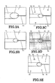
FIG. 3A, FIG. 3B, FIG. 3C, FIG. 3D and FIG. 3E are views showing diagrammatically an example of image information. -
FIG. 4A and FIG.4B are views showing diagrammatically an example of image information. - Embodiments of the invention are described below with reference to the drawings.
-
FIG. 1 is a view showing diagrammatically the layout of major parts of a laser irradiation device according to a first embodiment. Alaser irradiation device 100 comprises alaser oscillator 1, anoptical fiber 2 constituting laser beam transmission means, and a laser irradiation head 3: thelaser beam 4 generated by thelaser oscillator 1 is directed into thelaser irradiation head 3 by transmission using theoptical fiber 2. - Within the
laser irradiation head 3, there are arranged, in order from the rear end side (upper side inFIG. 1 ), a laserbeam adjustment unit 13 and a dichroic mirror 14: aprotective glass window 15 is arranged in the region of thelaser irradiation head 3 where thelaser beam 4 is emitted. Also, anozzle 16 is arranged in a portion at the leading end side (lower side inFIG. 1 ) of theprotective glass window 15. Thedichroic mirror 14 has the function of a reflection mechanism that, of the input light, gets the laser beam through the laser beam but reflects visible light. - Also, at the side of the
dichroic mirror 14, there is arranged areflective mirror 17 that reflects light that is reflected by thedichroic mirror 14; a wavelength-dependent screening mechanism 18, an imageadjustment lens unit 20, and a CCD (Charge-Coupled Device)camera 21 are arranged so as to be positioned on the optical path of the light reflected by thereflective mirror 17. In addition, animage processing mechanism 22 comprising for example a computer and a display is connected with theCCD camera 21. - The laser beam that is got through as far as the
laser irradiation head 3 by theoptical fiber 2 is directed into the laserbeam adjustment unit 13 in thelaser irradiation head 3. The laser beam that is emitted from theoptical fiber 2 spreads out during propagation in accordance with the incidence aperture number to theoptical fiber 2, so thelaser beam 4 is adjusted by the laserbeam adjustment unit 13, which comprises for example a plurality of lenses, to the necessary size for transmission as a parallel beam and is focused onto the point to be processed. Thelaser beam 4 emitted from the laserbeam adjustment unit 13 is directed onto the surface of the region to be processed while being gathered or focused, through thedichroic mirror 14,protective glass window 15 andnozzle 16. Thelaser beam 4 is thus focused to constitute a prescribed laser beam appropriate for laser processing at the time point of its incidence on the surface of the region to be processed. - At the surface of the region to be processed that is irradiated by the
laser beam 4, amelt pool 51 is formed in accordance with the focused spot diameter of thelaser beam 4, the laser output and the material of the region to be processed etc. Aweld bead 52 can thus be formed by moving the laser irradiation head while supplying forexample filler wire 53 to the melt pool. - Accompanying the formation of the
melt pool 51, fumes and sputter are scattered from the surface of the region to be processed that is irradiated by thelaser beam 4. Usually laser processing is performed whilst injecting a shielding gas, not shown, from the tip of anozzle 16, so the likelihood of fumes or sputter being deposited on the surface of theprotective glass shield 15 is low. Conventionally, however, it was not possible to confirm whether or not fumes or sputter were in fact deposited on the surface of theprotective glass window 15 without disassembling thelaser irradiation head 3. - In contrast, in the case of the
laser irradiation device 100 of this first embodiment, visible light is reflected by thedichroic mirror 14 that is arranged within thelaser irradiation head 3 and this visible light is picked up by theCCD camera 21 after passing through the reflectingmirror 17, wavelength-dependent screening mechanism 18 and image adjustment lens unit 20: the image that is thus picked up is then processed by theimage processing mechanism 22. Consequently, the image of the vicinity of themelt pool 51 and the image of the surface of theprotective glass window 15 can be checked. -
Light 24 including the laser beam produced at the surface of the region to be processed by reflection of theirradiated laser beam 4 from the vicinity of themelt pool 51 on the surface of the region to be processed, visible light and a noise component generated from the metallic plasma (i.e. laser beam + visible light + noise) is obtained as image information: at thedichroic mirror 14, of these, chiefly only the visible light component is reflected. - However, since the
dichroic mirror 14 is formed with a film by coating, it cannot reflect 100% of the visible light, and the noise component etc. of the infrared light region from the plasma generated during laser welding is also reflected by thedichroic mirror 14. Consequently, if the reflected light 23 (visible light + noise) from thedichroic mirror 14 were directly introduced into the CCD camera, it would not be possible to obtain the required image information, due to the effect of noise. - In the case of the
laser irradiation device 100 according to this first embodiment, the reflected light (visible light + noise) 23 from thedichroic mirror 14 is introduced into the wavelength-dependent screening mechanism 18 that is arranged in thelaser irradiation head 3, the noise component is thereby removed, andvisible light 19 with no noise component is thus obtained. - If for example a color filter is employed in the wavelength-
dependent screening mechanism 18, for example wavelength components longer than infrared can be removed, making it possible to obtain exclusivelyvisible light 19 as the image information. Also, if this is combined with use of an ultraviolet region color filter, noise components of wavelength in the ultraviolet region can be removed. Furthermore, by combining with a polarizing filter or neutral density filter or the like, image information can be obtained from which for example halation is removed. - The visible light 19 from which the noise components have been removed as described above by the wavelength-
dependent screening mechanism 18 passes through the imageadjustment lens unit 20 and is picked up by theCCD camera 21. The imageadjustment lens unit 20 comprises a mechanism capable of altering the focal point position by moving the lens position and, for example as shown inFIG. 3A , can check the condition at the location where thewire filler 53 is supplied to theweld pool 51 and welding is effected or can check the condition of the surface of theprotective glass window 15 as shown inFIG. 3B by changing over the focal point position to obtain an image of a position in which the focal point is matched therewith. Also, the imageadjustment lens unit 20 is provided with a viewing field angle alteration mechanism (zoom mechanism). - As mentioned above, the
image processing mechanism 22 comprises for example a computer and a display. Thisimage processing mechanism 22 is equipped with means for storing the image information obtained and comparison means for comparing the image information stored in this storage means with for example image information obtained in real time. - Describing the example of laser welding, initial image information in a healthy condition, as shown in
FIG. 3A and FIG. 3B , is stored in the storage means as information at the start of welding.FIG. 3A shows diagrammatically the condition in which the focal point position is matched with the welding location andFIG. 3B shows diagrammatically the condition in which the focal point is matched with the surface of theprotective glass window 15. InFIG. 3B ,welding beads 52 etc. are visible, to a reduced scale, beyond theprotective glass window 15. - If, subsequently, arrangements are made, after the lapse of some time from commencement of laser welding, to periodically store the image information in the storage means and to compare this image information by using the comparison means, it is possible to check whether or not laser welding is being implemented in a healthy condition, without such inconveniences as damage to the optical system of the
laser irradiation head 3. - Supposing for the moment that such damage has occurred, for example, as shown in
FIG. 3C , that sputter 54 has been deposited on part of the surface of theprotective glass window 15, or, for example as shown inFIG. 3D , that fumes 55 have been deposited on the surface of the protective glass window 15 (resulting in the entire image becoming cloudy), or the like conditions, this can be confirmed by using the image information. - Also, as in the case of welding in water, in a method in which welding is performed while spraying shielding gas from the tip of a
nozzle 16 with thelaser irradiation head 3 shown inFIG. 1 inserted in the water, if disruption of the condition of spraying of the shielding gas occurs, as shown inFIG. 3E , resulting in a condition in whichwater droplets 56 have been deposited on the surface of theprotective glass window 15, this can be identified. - Specifically, for example the image information in a healthy condition of the
laser irradiation head 3 stored in theimage processing mechanism 22 and the image information after laser processing can be compared and a diagnosis of health can be performed using the deviation obtained as a result of such comparisons. In this case, if for example more than a prescribed reference value of sputter has been deposited on theprotective glass window 15, the conclusion may be drawn for example that the health of the screen has been damaged. Also, by using theimage processing mechanism 22 to detect the amount of light, a determination of health can be performed based on the difference in the amount of light between the amount of light when thelaser irradiation head 3 is healthy, prior to laser processing and the amount of light after laser processing. In this case, if for example the amount of light has decreased due to deposition of fumes on the surface of theprotective glass window 15, so that the difference in the amount of light is more than a prescribed reference value, it can be concluded for example that the health of the laser irradiation head has been impaired. - As described above, by using the wavelength-
dependent screening mechanism 18 to remove wavelength components constituting noise from the reflected light (visible light + noise) 23 including noise components reflected by thedichroic mirror 14, and using the imageadjustment lens unit 20 to change over the focal point position, the image may be checked by theimage processing mechanism 22 while changing over the observation position: in this way, laser processing can be performed while checking the health of thelaser irradiation head 3 itself. - Also, owing to the adoption of a construction wherein reflected light from the surface of the region to be processed is branched by the
dichroic mirror 14 in thelaser welding head 3 before being input to theCCD camera 21, there is no need to make the construction of the parts of thelaser welding head 3 facing the region to be processed complicated or large in size. - Also, since, of the reflected light from the surface of the region to be processed, the reflected light that enters the optical path of the
laser beam 3 is picked up, theprotective glass window 15 etc. can be checked reliably, so long as it is in a condition in which processing can be achieved. It may be envisioned that if for example a construction were adopted in which an image of the protective glass window was picked up with the CCD camera etc. being provided on the side of thenozzle 16 of theprotective glass window 15, fumes or sputter penetrating between theprotective glass window 15 and this CCD camera could interfere with image pickup. - It should be noted that, although, in this embodiment, the description was given assuming that the
dichroic mirror 14 was provided between the laserbeam adjustment unit 13 and theprotective glass window 15, there is no restriction to this. So long as the reflected light that is directed onto theprotective glass window 15 from the optical path of the laser beam is branched before entering theCCD camera 21, the dichroic mirror could be provided for example between the laserbeam adjustment unit 13 and theoptical fiber 2. Alternatively, if the transmission distance of the laser beam is long, a plurality ofoptical fibers 2 may be connected by an optical repeater; however, a construction can be adopted in which the reflected light is branched in this optical repeater. - Although, in the above description, laser welding was described by way of example, there is no restriction to laser welding and it would be possible to apply the foregoing to laser processing in general, such as laser cutting or laser peening.
- Next, a second embodiment will be described with reference to
FIG. 2 . -
FIG. 2 is a view showing diagrammatically the layout of major parts of alaser irradiation device 200 according to a second embodiment. In thislaser irradiation device 200, adichroic mirror 14 that is arranged within thelaser irradiation head 3 comprises adrive mechanism 31; as shown inFIG. 1 , the position of thedichroic mirror 14 can be set at a position to reflect the visible light that is incident from the side of theprotective glass window 15 or a position to reflect the visible light that is incident from the side of the laserbeam adjustment unit 13, as shown inFIG. 2 . - Specifically, as shown by the arrows in
FIG. 2 , thedichroic mirror 14 is capable of rotation about arotation axis 30 by adrive mechanism 31. Thedichroic mirror 14 can thus be set in a position in which as shown inFIG. 1 , image information is obtained by input of visible light directed from the side of theprotective glass window 15 to theCCD camera 21 after reflection by thedichroic mirror 14, through thereflective mirror 17, optical wavelength-dependent screening mechanism 18, and imageadjustment lens unit 20, and a position in which as shown inFIG. 2 image information is obtained by input of visible light directed from the side of the laserbeam adjustment unit 13 to theCCD camera 21 after reflection, through the reflectingmirror 17, optical wavelength-dependent screening mechanism 18, and imageadjustment lens unit 20. Other parts which have the same construction as in the case of the first embodiment shown inFIG. 1 are given the same reference numerals as the corresponding parts, to avoid repetition of description. - The position of the
dichroic mirror 14 shown inFIG. 1 is a position at which image information of the laser processing region during for example laser processing or image information of the surface of theprotective glass window 15 is obtained; the position of thedichroic mirror 14 shown inFIG. 2 is a position in which image information of the internal optical system within thelaser irradiation head 3 is obtained when laser processing is not performed. - As shown in
FIG. 2 , although laser processing cannot be performed by directing the visible light reflecting face of thedichroic mirror 14 towards the side of the laserbeam adjustment unit 13, the condition of the optical system of the laserbeam adjustment unit 13 and, through this optical system, the condition of the end of theoptical fiber 2 can be viewed, so it is possible to check whether or not any damage to these has taken place. In this case also, a check is performed on the condition of the lens within the laserbeam adjustment unit 13 and the condition of the end of theoptical fiber 2 by employing the focal point position changeover function of the imageadjustment lens unit 20. - In particular, when the condition of the end of the
optical fiber 2 is to be checked, the diameter of the end of theoptical fiber 2 is smaller than for example the diameter of the internal lens of the laserbeam adjustment unit 13, so a field of view angle alteration mechanism (zoom mechanism) of the imageadjustment lens unit 20 is employed: it is thereby possible for example to obtain image information in a condition in which the end of theoptical fiber 2 is magnified, as shown inFIG. 4A . - If damage has occurred to the end face of the
optical fiber 2, for example if melting has occurred at the end face of theoptical fiber 2, the end face of theoptical fiber 2 will have assumed a built-up condition, so, as shown inFIG. 4B , an image will be obtained that is different from the circular image in the normal case shown inFIG. 4A , and this can be identified. (The example shown inFIG. 4B shows an elliptical shape. In fact, because of distortion of the end face of theoptical fiber 2, the shape is more distorted.) - An image obtained in the case where the
optical fiber 2 etc is normal, prior to commencement of laser processing, as shown inFIG. 4A is recorded in the storage section of the image processing mechanism 22: it is thus possible to perform laser processing with thelaser irradiation head 3 in a healthy condition, if the end face of theoptical fiber 2 and the internal optical system of the laserbeam adjustment unit 13 are periodically checked. - It should be noted that, when the optical system within the
laser irradiation head 3 is observed, if observation of the optical system in the interior is conducted while delivering from the laser oscillator 1 a laser beam of lower output (for example of around a few mW to 100W) than when laser processing is performed, it becomes easier to check the condition of the optical system in the interior than if this is done while performing irradiation with a laser beam. Also, the surface of the lens constituting the laserbeam adjustment unit 13 is coated with a reflection preventing film, and this reflection preventing film emits light when irradiated with a laser beam. - By periodically observing the interior of the
laser irradiation head 3 in this way, it is possible to perform laser processing with thelaser irradiation head 3 in a healthy condition. - While various embodiments of the present invention have been described above, these embodiments are presented by way of example and there is no intention to thereby restrict the scope of the invention. Novel embodiments of these can be put into practice in various modified ways and various deletions, substitutions or alterations may be made within a scope not departing from the gist of the invention. Such embodiments and modifications thereof are included within the scope and gist of the invention and are included in the scope of the invention set out in the patent claims and equivalents thereof.
Claims (7)
- A laser irradiation device having(1) a laser oscillator that generates a laser beam;(2) a laser irradiation head that performs laser processing by directing a laser beam generated by said laser oscillator onto a region to be processed; and(3) a transmission mechanism that gets said laser beam through emitted from said laser oscillator to said laser irradiation head,wherein said laser irradiation head comprises:(a) a protective glass window arranged in an emission region that emits said laser beam of said irradiation head onto said region to be processed;(b) a reflection mechanism, provided within said irradiation head, that gets said laser beam through and reflects at least visible light, of reflected lights from said region to be processed;(c) an image pickup camera that inputs said light reflected by said reflection mechanism; and(d) an image adjustment optical system, provided between said reflection mechanism and said image pickup camera, whereby a focal point position of said image pickup camera can be changed over to a position of at least said protective glass window and said region to be processed.
- The laser irradiation device according to claim 1, wherein said reflection mechanism comprises a dichroic mirror, arranged on an optical path of said laser beam got through from said transmission mechanism to said protective glass window.
- The laser irradiation device according to claim 2, wherein said dichroic mirror is equipped with a drive mechanism and is capable of being set in a position in which said dichroic mirror reflects visible light that is incident from a side of said protective glass window and a position in which said dichroic mirror reflects visible light that is incident from a side of said laser beam adjustment unit.
- The laser irradiation device according to any of claim 1 to 3, further comprising
an image processing mechanism that processes an image that is picked up by said image pickup camera, and wherein said image processing mechanism comprises a storage section that stores an image, and said image processing mechanism determines a health on a basis of the detected deviations obtained by comparing an image before laser processing stored in said storage section and an image after laser processing. - The laser irradiation device according to any of claims 1 to 4,
wherein said image processing mechanism is equipped with an amount of light measurement mechanism and determines a health based on differences in amounts of light before and after laser processing. - The laser irradiation device according to any of claims 1 to 5,
wherein image processing by said image processing mechanism is performed while delivering a laser beam of lower output than during laser processing from said laser oscillator. - A method of diagnosing a health of a laser irradiation head, there being provided:(1) a laser oscillator that generates a laser beam;(2) a laser irradiation head that performs laser processing by directing a laser beam generated from said laser oscillator onto a region to be processed; and(3) a transmission mechanism that gets said laser beam through generated from said laser oscillator to said laser irradiation head,
wherein said laser irradiation head comprises:(a) a laser beam adjustment unit that produces a laser beam directed onto said region to be processed by adjusting said laser beam from said transmission mechanism; and(b) a protective glass window arranged in an emission section that emits a laser beam, andwherein said health of said laser irradiation head of said laser irradiation device is diagnosed,
wherein there are arranged in said laser irradiation head:(i) a reflection mechanism provided within said irradiation head, that gets said laser beam through and that reflects at least visible light of a reflected light from said region to be processed;(ii) an image pickup camera that inputs said light reflected by said reflection mechanism; and(iii) an image adjustment optical system provided between said reflection mechanism and said image pickup camera, capable of changing over a focal point position of said image pickup camera to at least a position of said protective glass window and said region to be processed; andsaid health of said laser irradiation head is diagnosed using an image picked up by said image pickup camera.
Applications Claiming Priority (2)
| Application Number | Priority Date | Filing Date | Title |
|---|---|---|---|
| JP2011228002 | 2011-10-17 | ||
| PCT/JP2012/006628 WO2013057935A1 (en) | 2011-10-17 | 2012-10-17 | Laser irradiation device and method for diagnosing integrity of laser irradiation head |
Publications (3)
| Publication Number | Publication Date |
|---|---|
| EP2769799A1 true EP2769799A1 (en) | 2014-08-27 |
| EP2769799A4 EP2769799A4 (en) | 2015-12-16 |
| EP2769799B1 EP2769799B1 (en) | 2019-04-03 |
Family
ID=48140600
Family Applications (1)
| Application Number | Title | Priority Date | Filing Date |
|---|---|---|---|
| EP12842462.9A Not-in-force EP2769799B1 (en) | 2011-10-17 | 2012-10-17 | Laser irradiation device and method for diagnosing integrity of laser irradiation head |
Country Status (5)
| Country | Link |
|---|---|
| US (1) | US9662744B2 (en) |
| EP (1) | EP2769799B1 (en) |
| JP (1) | JP6049391B2 (en) |
| KR (1) | KR101695930B1 (en) |
| WO (1) | WO2013057935A1 (en) |
Cited By (1)
| Publication number | Priority date | Publication date | Assignee | Title |
|---|---|---|---|---|
| CN111093886A (en) * | 2017-09-11 | 2020-05-01 | 松下知识产权经营株式会社 | Laser processing head, optical fiber inspection device, and optical fiber inspection method |
Families Citing this family (20)
| Publication number | Priority date | Publication date | Assignee | Title |
|---|---|---|---|---|
| EP2957378A1 (en) * | 2014-06-16 | 2015-12-23 | Synova SA | Machining head for coupling a laser beam and a fluid beam with an interface |
| JP6430815B2 (en) * | 2014-12-26 | 2018-11-28 | パナソニック デバイスSunx株式会社 | Laser processing apparatus, setting apparatus for laser processing apparatus, and setting program for laser processing apparatus |
| JP6385997B2 (en) * | 2016-09-16 | 2018-09-05 | 本田技研工業株式会社 | Laser welding method and laser welding apparatus |
| JP6431937B2 (en) * | 2017-01-25 | 2018-11-28 | 株式会社アマダホールディングス | Laser processing machine |
| JP6680751B2 (en) | 2017-11-24 | 2020-04-15 | ファナック株式会社 | Laser processing equipment that warns of dirt on the protective window during laser processing |
| JP7020896B2 (en) * | 2017-12-14 | 2022-02-16 | 株式会社キーエンス | Laser processing equipment |
| FR3085205B1 (en) | 2018-08-22 | 2020-07-24 | Livbag Sas | LASER WELDER PROTECTIVE GLASS CONTROL DEVICE AND METHOD |
| US10828836B2 (en) | 2018-12-13 | 2020-11-10 | General Electric Company | Method for melt pool monitoring |
| US11285671B2 (en) | 2018-12-13 | 2022-03-29 | General Electric Company | Method for melt pool monitoring using Green's theorem |
| US10894364B2 (en) | 2018-12-13 | 2021-01-19 | General Electric Company | Method for melt pool monitoring using geometric length |
| US11020907B2 (en) | 2018-12-13 | 2021-06-01 | General Electric Company | Method for melt pool monitoring using fractal dimensions |
| US10828837B2 (en) | 2018-12-13 | 2020-11-10 | General Electric Company | Method for melt pool monitoring using algebraic connectivity |
| JP2020199517A (en) | 2019-06-07 | 2020-12-17 | ファナック株式会社 | Laser machining system |
| KR102353291B1 (en) * | 2019-10-22 | 2022-01-21 | 배한성 | Laser beam quality measuring device |
| US11734810B2 (en) | 2020-07-15 | 2023-08-22 | Mitsubishi Electric Corporation | Laser system, learning device, and inference device |
| WO2022050436A1 (en) * | 2020-09-03 | 2022-03-10 | 엘지전자 주식회사 | Laser processing apparatus |
| KR102265517B1 (en) * | 2020-12-01 | 2021-06-15 | 이한종 | Composite laser cutter with fiber laser and CO₂laser |
| JP2022102125A (en) * | 2020-12-25 | 2022-07-07 | ブラザー工業株式会社 | Laser processing equipment and its control program, detection method |
| EP4082711A1 (en) * | 2021-04-28 | 2022-11-02 | TRUMPF Schweiz AG | Laser processing machine and method for monitoring an optical element arranged in the laser beam path |
| KR102532703B1 (en) * | 2022-03-18 | 2023-05-15 | 문동원 | Laser marking device for food packaging that simultaneously processes date stamping and vision inspection |
Family Cites Families (22)
| Publication number | Priority date | Publication date | Assignee | Title |
|---|---|---|---|---|
| EP0212786A1 (en) * | 1985-08-02 | 1987-03-04 | C.R. Bard, Inc. | Laser/optical fiber safety apparatus and method |
| JPH0716795B2 (en) * | 1988-01-19 | 1995-03-01 | ミヤチテクノス株式会社 | Laser emission port protection glass plate dirt detection device |
| JPH04118193A (en) * | 1990-09-04 | 1992-04-20 | Hitachi Constr Mach Co Ltd | Device for monitoring protective glass of laser beam machine |
| DE4106007A1 (en) * | 1991-02-26 | 1992-09-03 | Fraunhofer Ges Forschung | METHOD AND DEVICE FOR MACHINING WORKPIECES WITH LASER RADIATION |
| JP2720744B2 (en) * | 1992-12-28 | 1998-03-04 | 三菱電機株式会社 | Laser processing machine |
| US5449882A (en) * | 1993-03-15 | 1995-09-12 | Reliant Laser Corporation | Mirror-based laser-processing system with temperature and position control of moving laser spot |
| JPH0957479A (en) * | 1995-08-28 | 1997-03-04 | Amada Co Ltd | Laser machining head |
| JPH09199845A (en) * | 1996-01-19 | 1997-07-31 | Toshiba Corp | YAG laser heating device |
| SE508426C2 (en) * | 1997-01-24 | 1998-10-05 | Permanova Lasersystem Ab | Method and apparatus for monitoring the purity of a protective glass in laser machining |
| JP3038196B1 (en) * | 1998-10-30 | 2000-05-08 | ファナック株式会社 | Laser light concentrator |
| JP3404627B2 (en) * | 1999-09-10 | 2003-05-12 | 住友重機械工業株式会社 | Laser processing machine |
| JP3752112B2 (en) | 1999-09-28 | 2006-03-08 | 三菱重工業株式会社 | Laser processing apparatus and laser processing head |
| DE10310854B3 (en) * | 2003-03-11 | 2004-09-30 | Erlas Erlanger Lasertechnik Gmbh | Method, monitoring device and laser processing system with defect monitoring of an optical component |
| JP4155095B2 (en) * | 2003-05-13 | 2008-09-24 | 松下電器産業株式会社 | Optical processing equipment |
| KR100631181B1 (en) * | 2004-05-13 | 2006-10-02 | (주)한빛레이저 | Plasma light blocking coaxial video surveillance laser processing device. |
| JP2007054881A (en) * | 2005-08-26 | 2007-03-08 | Miyachi Technos Corp | Laser processing monitoring device |
| JP2008173659A (en) * | 2007-01-17 | 2008-07-31 | Japan Unix Co Ltd | Laser head for soldering |
| JP5137488B2 (en) | 2007-07-25 | 2013-02-06 | オリンパス株式会社 | Laser irradiation apparatus and laser processing system using the same |
| JP5209290B2 (en) * | 2007-12-14 | 2013-06-12 | ミヤチテクノス株式会社 | Laser processing monitoring device and laser processing device |
| DE102009007769B4 (en) * | 2009-02-05 | 2016-07-14 | Jenoptik Automatisierungstechnik Gmbh | Laser processing head with integrated sensor device for focus position monitoring |
| JP5504679B2 (en) * | 2009-04-02 | 2014-05-28 | 株式会社Ihi | Laser welding apparatus and laser welding method |
| EP4134118B1 (en) * | 2015-07-30 | 2024-11-27 | Trudell Medical International Inc. | Combined respiratory muscle training and oscillating positive expiratory pressure device |
-
2012
- 2012-10-17 JP JP2012229917A patent/JP6049391B2/en active Active
- 2012-10-17 KR KR1020147009988A patent/KR101695930B1/en not_active Expired - Fee Related
- 2012-10-17 WO PCT/JP2012/006628 patent/WO2013057935A1/en not_active Ceased
- 2012-10-17 EP EP12842462.9A patent/EP2769799B1/en not_active Not-in-force
-
2014
- 2014-04-16 US US14/254,184 patent/US9662744B2/en not_active Expired - Fee Related
Cited By (2)
| Publication number | Priority date | Publication date | Assignee | Title |
|---|---|---|---|---|
| CN111093886A (en) * | 2017-09-11 | 2020-05-01 | 松下知识产权经营株式会社 | Laser processing head, optical fiber inspection device, and optical fiber inspection method |
| EP3683002A4 (en) * | 2017-09-11 | 2020-11-04 | Panasonic Intellectual Property Management Co., Ltd. | LASER PROCESSING HEAD, FIBER TESTING DEVICE AND METHOD FOR TESTING FIBERGLASS |
Also Published As
| Publication number | Publication date |
|---|---|
| US9662744B2 (en) | 2017-05-30 |
| EP2769799B1 (en) | 2019-04-03 |
| WO2013057935A1 (en) | 2013-04-25 |
| US20140224780A1 (en) | 2014-08-14 |
| EP2769799A4 (en) | 2015-12-16 |
| JP2013099783A (en) | 2013-05-23 |
| KR20140062518A (en) | 2014-05-23 |
| KR101695930B1 (en) | 2017-01-12 |
| JP6049391B2 (en) | 2016-12-21 |
Similar Documents
| Publication | Publication Date | Title |
|---|---|---|
| EP2769799B1 (en) | Laser irradiation device and method for diagnosing integrity of laser irradiation head | |
| JP5819727B2 (en) | Laser welding quality determination method and quality determination device | |
| EP3330038B1 (en) | Laser cladding head and method of operating a laser cladding system | |
| JP6659654B2 (en) | Laser processing equipment that warns of external optical system abnormality before laser processing | |
| EP3330035A1 (en) | Laser cladding system and method | |
| US20030029845A1 (en) | Repair method for structure and repair welding apparatus | |
| DE102011119478B4 (en) | Device for the externally illuminated visualization of a processing process carried out by means of a high-energy machining beam and deflecting element | |
| CN112276344B (en) | Focus positioning method for ultrafast laser cutting of transparent material | |
| Borden et al. | Improved method for laser damage testing coated optics | |
| CN110744213A (en) | In-situ monitoring device and method for pollution of welding laser head protective lens | |
| CN111479648B (en) | Apparatus, method and use for monitoring beam processing of workpieces | |
| JP4324052B2 (en) | Laser welding quality evaluation method | |
| CN101795810A (en) | Laser welding quality evaluation method and its device | |
| CN101396769B (en) | Apparatus for welding spacer grid | |
| JP3038196B1 (en) | Laser light concentrator | |
| JPH10328860A (en) | Laser welding method and laser welding device | |
| DE102009052529A1 (en) | Monitoring quality of laser-welded or -soldered seam, employs camera to take images revealing thermal dissipation immediately after completing each point of seam | |
| US6271499B1 (en) | Method for welding electroformed material to other electroformed material, at least one of which having an optical pattern on a surface thereof | |
| Oezmert et al. | Detectability of penetration based on weld pool geometry and process emission spectrum in laser welding of copper | |
| KR100922160B1 (en) | Laser welding device capable of eliminating image distortion caused by hot spots generated during support grid image during or after laser welding | |
| US20240269771A1 (en) | Laser welding method, laser welding device, and computer program product | |
| JP7775819B2 (en) | How to judge the quality of laser processing | |
| Hellwig et al. | Investigation on material removal mechanism of steel by means of laser processing for balancing processes | |
| US20260077429A1 (en) | Laser beam dimming device | |
| JP6452507B2 (en) | Laser welding equipment |
Legal Events
| Date | Code | Title | Description |
|---|---|---|---|
| PUAI | Public reference made under article 153(3) epc to a published international application that has entered the european phase |
Free format text: ORIGINAL CODE: 0009012 |
|
| 17P | Request for examination filed |
Effective date: 20140411 |
|
| AK | Designated contracting states |
Kind code of ref document: A1 Designated state(s): AL AT BE BG CH CY CZ DE DK EE ES FI FR GB GR HR HU IE IS IT LI LT LU LV MC MK MT NL NO PL PT RO RS SE SI SK SM TR |
|
| DAX | Request for extension of the european patent (deleted) | ||
| RA4 | Supplementary search report drawn up and despatched (corrected) |
Effective date: 20151116 |
|
| RIC1 | Information provided on ipc code assigned before grant |
Ipc: B23K 26/00 20140101AFI20151110BHEP Ipc: B23K 26/70 20140101ALI20151110BHEP Ipc: H01S 3/00 20060101ALI20151110BHEP Ipc: B23K 26/06 20140101ALI20151110BHEP |
|
| GRAP | Despatch of communication of intention to grant a patent |
Free format text: ORIGINAL CODE: EPIDOSNIGR1 |
|
| STAA | Information on the status of an ep patent application or granted ep patent |
Free format text: STATUS: GRANT OF PATENT IS INTENDED |
|
| RIC1 | Information provided on ipc code assigned before grant |
Ipc: H01S 3/00 20060101ALI20181024BHEP Ipc: B23K 26/70 20140101ALI20181024BHEP Ipc: B23K 26/00 20140101AFI20181024BHEP Ipc: B23K 26/06 20140101ALI20181024BHEP |
|
| INTG | Intention to grant announced |
Effective date: 20181120 |
|
| GRAS | Grant fee paid |
Free format text: ORIGINAL CODE: EPIDOSNIGR3 |
|
| GRAA | (expected) grant |
Free format text: ORIGINAL CODE: 0009210 |
|
| STAA | Information on the status of an ep patent application or granted ep patent |
Free format text: STATUS: THE PATENT HAS BEEN GRANTED |
|
| AK | Designated contracting states |
Kind code of ref document: B1 Designated state(s): AL AT BE BG CH CY CZ DE DK EE ES FI FR GB GR HR HU IE IS IT LI LT LU LV MC MK MT NL NO PL PT RO RS SE SI SK SM TR |
|
| REG | Reference to a national code |
Ref country code: GB Ref legal event code: FG4D |
|
| REG | Reference to a national code |
Ref country code: CH Ref legal event code: EP Ref country code: AT Ref legal event code: REF Ref document number: 1115127 Country of ref document: AT Kind code of ref document: T Effective date: 20190415 |
|
| REG | Reference to a national code |
Ref country code: DE Ref legal event code: R096 Ref document number: 602012058674 Country of ref document: DE |
|
| REG | Reference to a national code |
Ref country code: IE Ref legal event code: FG4D |
|
| REG | Reference to a national code |
Ref country code: NL Ref legal event code: MP Effective date: 20190403 |
|
| REG | Reference to a national code |
Ref country code: LT Ref legal event code: MG4D |
|
| REG | Reference to a national code |
Ref country code: AT Ref legal event code: MK05 Ref document number: 1115127 Country of ref document: AT Kind code of ref document: T Effective date: 20190403 |
|
| PG25 | Lapsed in a contracting state [announced via postgrant information from national office to epo] |
Ref country code: NL Free format text: LAPSE BECAUSE OF FAILURE TO SUBMIT A TRANSLATION OF THE DESCRIPTION OR TO PAY THE FEE WITHIN THE PRESCRIBED TIME-LIMIT Effective date: 20190403 |
|
| PG25 | Lapsed in a contracting state [announced via postgrant information from national office to epo] |
Ref country code: HR Free format text: LAPSE BECAUSE OF FAILURE TO SUBMIT A TRANSLATION OF THE DESCRIPTION OR TO PAY THE FEE WITHIN THE PRESCRIBED TIME-LIMIT Effective date: 20190403 Ref country code: LT Free format text: LAPSE BECAUSE OF FAILURE TO SUBMIT A TRANSLATION OF THE DESCRIPTION OR TO PAY THE FEE WITHIN THE PRESCRIBED TIME-LIMIT Effective date: 20190403 Ref country code: FI Free format text: LAPSE BECAUSE OF FAILURE TO SUBMIT A TRANSLATION OF THE DESCRIPTION OR TO PAY THE FEE WITHIN THE PRESCRIBED TIME-LIMIT Effective date: 20190403 Ref country code: ES Free format text: LAPSE BECAUSE OF FAILURE TO SUBMIT A TRANSLATION OF THE DESCRIPTION OR TO PAY THE FEE WITHIN THE PRESCRIBED TIME-LIMIT Effective date: 20190403 Ref country code: NO Free format text: LAPSE BECAUSE OF FAILURE TO SUBMIT A TRANSLATION OF THE DESCRIPTION OR TO PAY THE FEE WITHIN THE PRESCRIBED TIME-LIMIT Effective date: 20190703 Ref country code: AL Free format text: LAPSE BECAUSE OF FAILURE TO SUBMIT A TRANSLATION OF THE DESCRIPTION OR TO PAY THE FEE WITHIN THE PRESCRIBED TIME-LIMIT Effective date: 20190403 Ref country code: PT Free format text: LAPSE BECAUSE OF FAILURE TO SUBMIT A TRANSLATION OF THE DESCRIPTION OR TO PAY THE FEE WITHIN THE PRESCRIBED TIME-LIMIT Effective date: 20190803 Ref country code: SE Free format text: LAPSE BECAUSE OF FAILURE TO SUBMIT A TRANSLATION OF THE DESCRIPTION OR TO PAY THE FEE WITHIN THE PRESCRIBED TIME-LIMIT Effective date: 20190403 Ref country code: CZ Free format text: LAPSE BECAUSE OF FAILURE TO SUBMIT A TRANSLATION OF THE DESCRIPTION OR TO PAY THE FEE WITHIN THE PRESCRIBED TIME-LIMIT Effective date: 20190403 |
|
| PG25 | Lapsed in a contracting state [announced via postgrant information from national office to epo] |
Ref country code: BG Free format text: LAPSE BECAUSE OF FAILURE TO SUBMIT A TRANSLATION OF THE DESCRIPTION OR TO PAY THE FEE WITHIN THE PRESCRIBED TIME-LIMIT Effective date: 20190703 Ref country code: GR Free format text: LAPSE BECAUSE OF FAILURE TO SUBMIT A TRANSLATION OF THE DESCRIPTION OR TO PAY THE FEE WITHIN THE PRESCRIBED TIME-LIMIT Effective date: 20190704 Ref country code: RS Free format text: LAPSE BECAUSE OF FAILURE TO SUBMIT A TRANSLATION OF THE DESCRIPTION OR TO PAY THE FEE WITHIN THE PRESCRIBED TIME-LIMIT Effective date: 20190403 Ref country code: LV Free format text: LAPSE BECAUSE OF FAILURE TO SUBMIT A TRANSLATION OF THE DESCRIPTION OR TO PAY THE FEE WITHIN THE PRESCRIBED TIME-LIMIT Effective date: 20190403 Ref country code: PL Free format text: LAPSE BECAUSE OF FAILURE TO SUBMIT A TRANSLATION OF THE DESCRIPTION OR TO PAY THE FEE WITHIN THE PRESCRIBED TIME-LIMIT Effective date: 20190403 |
|
| PG25 | Lapsed in a contracting state [announced via postgrant information from national office to epo] |
Ref country code: IS Free format text: LAPSE BECAUSE OF FAILURE TO SUBMIT A TRANSLATION OF THE DESCRIPTION OR TO PAY THE FEE WITHIN THE PRESCRIBED TIME-LIMIT Effective date: 20190803 Ref country code: AT Free format text: LAPSE BECAUSE OF FAILURE TO SUBMIT A TRANSLATION OF THE DESCRIPTION OR TO PAY THE FEE WITHIN THE PRESCRIBED TIME-LIMIT Effective date: 20190403 |
|
| REG | Reference to a national code |
Ref country code: DE Ref legal event code: R097 Ref document number: 602012058674 Country of ref document: DE |
|
| PG25 | Lapsed in a contracting state [announced via postgrant information from national office to epo] |
Ref country code: EE Free format text: LAPSE BECAUSE OF FAILURE TO SUBMIT A TRANSLATION OF THE DESCRIPTION OR TO PAY THE FEE WITHIN THE PRESCRIBED TIME-LIMIT Effective date: 20190403 Ref country code: DK Free format text: LAPSE BECAUSE OF FAILURE TO SUBMIT A TRANSLATION OF THE DESCRIPTION OR TO PAY THE FEE WITHIN THE PRESCRIBED TIME-LIMIT Effective date: 20190403 Ref country code: SK Free format text: LAPSE BECAUSE OF FAILURE TO SUBMIT A TRANSLATION OF THE DESCRIPTION OR TO PAY THE FEE WITHIN THE PRESCRIBED TIME-LIMIT Effective date: 20190403 Ref country code: RO Free format text: LAPSE BECAUSE OF FAILURE TO SUBMIT A TRANSLATION OF THE DESCRIPTION OR TO PAY THE FEE WITHIN THE PRESCRIBED TIME-LIMIT Effective date: 20190403 |
|
| PLBE | No opposition filed within time limit |
Free format text: ORIGINAL CODE: 0009261 |
|
| STAA | Information on the status of an ep patent application or granted ep patent |
Free format text: STATUS: NO OPPOSITION FILED WITHIN TIME LIMIT |
|
| PG25 | Lapsed in a contracting state [announced via postgrant information from national office to epo] |
Ref country code: IT Free format text: LAPSE BECAUSE OF FAILURE TO SUBMIT A TRANSLATION OF THE DESCRIPTION OR TO PAY THE FEE WITHIN THE PRESCRIBED TIME-LIMIT Effective date: 20190403 Ref country code: SM Free format text: LAPSE BECAUSE OF FAILURE TO SUBMIT A TRANSLATION OF THE DESCRIPTION OR TO PAY THE FEE WITHIN THE PRESCRIBED TIME-LIMIT Effective date: 20190403 |
|
| 26N | No opposition filed |
Effective date: 20200106 |
|
| PG25 | Lapsed in a contracting state [announced via postgrant information from national office to epo] |
Ref country code: TR Free format text: LAPSE BECAUSE OF FAILURE TO SUBMIT A TRANSLATION OF THE DESCRIPTION OR TO PAY THE FEE WITHIN THE PRESCRIBED TIME-LIMIT Effective date: 20190403 |
|
| PG25 | Lapsed in a contracting state [announced via postgrant information from national office to epo] |
Ref country code: SI Free format text: LAPSE BECAUSE OF FAILURE TO SUBMIT A TRANSLATION OF THE DESCRIPTION OR TO PAY THE FEE WITHIN THE PRESCRIBED TIME-LIMIT Effective date: 20190403 Ref country code: MC Free format text: LAPSE BECAUSE OF FAILURE TO SUBMIT A TRANSLATION OF THE DESCRIPTION OR TO PAY THE FEE WITHIN THE PRESCRIBED TIME-LIMIT Effective date: 20190403 |
|
| REG | Reference to a national code |
Ref country code: CH Ref legal event code: PL |
|
| PG25 | Lapsed in a contracting state [announced via postgrant information from national office to epo] |
Ref country code: LI Free format text: LAPSE BECAUSE OF NON-PAYMENT OF DUE FEES Effective date: 20191031 Ref country code: LU Free format text: LAPSE BECAUSE OF NON-PAYMENT OF DUE FEES Effective date: 20191017 Ref country code: CH Free format text: LAPSE BECAUSE OF NON-PAYMENT OF DUE FEES Effective date: 20191031 |
|
| REG | Reference to a national code |
Ref country code: BE Ref legal event code: MM Effective date: 20191031 |
|
| PG25 | Lapsed in a contracting state [announced via postgrant information from national office to epo] |
Ref country code: BE Free format text: LAPSE BECAUSE OF NON-PAYMENT OF DUE FEES Effective date: 20191031 |
|
| GBPC | Gb: european patent ceased through non-payment of renewal fee |
Effective date: 20191017 |
|
| PG25 | Lapsed in a contracting state [announced via postgrant information from national office to epo] |
Ref country code: GB Free format text: LAPSE BECAUSE OF NON-PAYMENT OF DUE FEES Effective date: 20191017 Ref country code: IE Free format text: LAPSE BECAUSE OF NON-PAYMENT OF DUE FEES Effective date: 20191017 |
|
| PG25 | Lapsed in a contracting state [announced via postgrant information from national office to epo] |
Ref country code: CY Free format text: LAPSE BECAUSE OF FAILURE TO SUBMIT A TRANSLATION OF THE DESCRIPTION OR TO PAY THE FEE WITHIN THE PRESCRIBED TIME-LIMIT Effective date: 20190403 |
|
| PG25 | Lapsed in a contracting state [announced via postgrant information from national office to epo] |
Ref country code: HU Free format text: LAPSE BECAUSE OF FAILURE TO SUBMIT A TRANSLATION OF THE DESCRIPTION OR TO PAY THE FEE WITHIN THE PRESCRIBED TIME-LIMIT; INVALID AB INITIO Effective date: 20121017 Ref country code: MT Free format text: LAPSE BECAUSE OF FAILURE TO SUBMIT A TRANSLATION OF THE DESCRIPTION OR TO PAY THE FEE WITHIN THE PRESCRIBED TIME-LIMIT Effective date: 20190403 |
|
| PGFP | Annual fee paid to national office [announced via postgrant information from national office to epo] |
Ref country code: FR Payment date: 20210913 Year of fee payment: 10 |
|
| PGFP | Annual fee paid to national office [announced via postgrant information from national office to epo] |
Ref country code: DE Payment date: 20210908 Year of fee payment: 10 |
|
| PG25 | Lapsed in a contracting state [announced via postgrant information from national office to epo] |
Ref country code: MK Free format text: LAPSE BECAUSE OF FAILURE TO SUBMIT A TRANSLATION OF THE DESCRIPTION OR TO PAY THE FEE WITHIN THE PRESCRIBED TIME-LIMIT Effective date: 20190403 |
|
| REG | Reference to a national code |
Ref country code: DE Ref legal event code: R119 Ref document number: 602012058674 Country of ref document: DE |
|
| PG25 | Lapsed in a contracting state [announced via postgrant information from national office to epo] |
Ref country code: FR Free format text: LAPSE BECAUSE OF NON-PAYMENT OF DUE FEES Effective date: 20221031 Ref country code: DE Free format text: LAPSE BECAUSE OF NON-PAYMENT OF DUE FEES Effective date: 20230503 |