EP2769702B1 - Brace for articulation - Google Patents
Brace for articulation Download PDFInfo
- Publication number
- EP2769702B1 EP2769702B1 EP14425016.4A EP14425016A EP2769702B1 EP 2769702 B1 EP2769702 B1 EP 2769702B1 EP 14425016 A EP14425016 A EP 14425016A EP 2769702 B1 EP2769702 B1 EP 2769702B1
- Authority
- EP
- European Patent Office
- Prior art keywords
- selector
- rod
- adjustment
- brace
- blocking member
- Prior art date
- Legal status (The legal status is an assumption and is not a legal conclusion. Google has not performed a legal analysis and makes no representation as to the accuracy of the status listed.)
- Active
Links
Images


Classifications
-
- F—MECHANICAL ENGINEERING; LIGHTING; HEATING; WEAPONS; BLASTING
- F16—ENGINEERING ELEMENTS AND UNITS; GENERAL MEASURES FOR PRODUCING AND MAINTAINING EFFECTIVE FUNCTIONING OF MACHINES OR INSTALLATIONS; THERMAL INSULATION IN GENERAL
- F16C—SHAFTS; FLEXIBLE SHAFTS; ELEMENTS OR CRANKSHAFT MECHANISMS; ROTARY BODIES OTHER THAN GEARING ELEMENTS; BEARINGS
- F16C11/00—Pivots; Pivotal connections
- F16C11/04—Pivotal connections
- F16C11/10—Arrangements for locking
-
- A—HUMAN NECESSITIES
- A61—MEDICAL OR VETERINARY SCIENCE; HYGIENE
- A61F—FILTERS IMPLANTABLE INTO BLOOD VESSELS; PROSTHESES; DEVICES PROVIDING PATENCY TO, OR PREVENTING COLLAPSING OF, TUBULAR STRUCTURES OF THE BODY, e.g. STENTS; ORTHOPAEDIC, NURSING OR CONTRACEPTIVE DEVICES; FOMENTATION; TREATMENT OR PROTECTION OF EYES OR EARS; BANDAGES, DRESSINGS OR ABSORBENT PADS; FIRST-AID KITS
- A61F5/00—Orthopaedic methods or devices for non-surgical treatment of bones or joints; Nursing devices ; Anti-rape devices
- A61F5/01—Orthopaedic devices, e.g. long-term immobilising or pressure directing devices for treating broken or deformed bones such as splints, casts or braces
- A61F5/0102—Orthopaedic devices, e.g. long-term immobilising or pressure directing devices for treating broken or deformed bones such as splints, casts or braces specially adapted for correcting deformities of the limbs or for supporting them; Ortheses, e.g. with articulations
- A61F2005/0132—Additional features of the articulation
- A61F2005/0165—Additional features of the articulation with limits of movement
- A61F2005/0167—Additional features of the articulation with limits of movement adjustable
-
- Y—GENERAL TAGGING OF NEW TECHNOLOGICAL DEVELOPMENTS; GENERAL TAGGING OF CROSS-SECTIONAL TECHNOLOGIES SPANNING OVER SEVERAL SECTIONS OF THE IPC; TECHNICAL SUBJECTS COVERED BY FORMER USPC CROSS-REFERENCE ART COLLECTIONS [XRACs] AND DIGESTS
- Y10—TECHNICAL SUBJECTS COVERED BY FORMER USPC
- Y10T—TECHNICAL SUBJECTS COVERED BY FORMER US CLASSIFICATION
- Y10T403/00—Joints and connections
- Y10T403/32—Articulated members
- Y10T403/32254—Lockable at fixed position
- Y10T403/32426—Plural distinct positions
Definitions
- the present invention relates to a brace for articulation.
- the invention concerns an ambidextrous brace, studied and realized in particular for post-traumatic or post-operative recovery of the elbow joint, but which can also be used for knee joint, when supporting the knee in after traumatic or post operating rehabilitation phases is necessary.
- braces comprising two rods coupled together by means of a rotary joint that can be blocked by means of buttons in order to maintain fixed said rods between them at a predetermined angle.
- the two rods are positioned with one on the arm and one on the forearm of the patient, so that the rotary joint is in correspondence with the elbow and they are fixed to the patient's body through sheaths or sleeves with twist fasteners, snap or similar means.
- a brace example according to the prior art is represented by U.S. patent US 6,080,122 , which relates to a brace for an arm comprising two rods connected to each other by a coupling comprising a circular ring, toothed along a circumference arc .
- Said ring is integral with one of the two arms while it is rotatably coupled with the second arm by means of a central pivot.
- the ring is rotatably connected with a flat base through a central pivot.
- Said flat base further includes a pivot that fits progressively along indentations of the ring circumference arc, corresponding to the rotation imparted on the flat base.
- Additional pivots block the excursion of the two rods, so that, when the flat base is rotated and fixed at a predetermined angle, the rods rotate accordingly, by means of the toothed ring and are blocked by locking pins. In this way, patient's arm is fixed at a predetermined position, which inhibits the flexion and extension, thus limiting the ROM of the arm.
- This brace allows arms to rotate between them according to a predetermined angle from 0° to 180° as they have indentations, guides or grooves that prevent a rotation of the rods between them at a higher angle.
- Each of the patent documents US5827208A , US5814000A and US 2011/814887A1 describes a brace for articulation according to the preamble of claim 1.
- braces of the state of the art have joints composed of a plurality of mechanical elements such as pivots, rollers, elastic returning means and screws, which makes the structure of the joints complex. It is evident, therefore, how easily a joint can be damaged due to the failure even of a single pivot or a mechanical piece that composes it, thus requiring frequent maintenance of the brace.
- object of the present invention providing an ambidextrous brace, which can then be used indifferently for both the articulation of a right or a left limb.
- Another object of the invention is to provide a brace comprising a joint having a simple mechanical structure and comprised of a few mechanical parts subject to wear and malfunction.
- brace for articulation comprising a first rod, a second rod, having a through hole at one end, and a joint for connecting said first rod and said second rod, wherein said joint comprises a pair of circular toothed rings, provided with a central hole and arranged overlapping, each circular ring is fixed to one end of said first rod, which is interposed between them, said second rod being interposed between said circular rings, a fixing central pivot, inserted in said central holes of said circular rings and into said through hole of said second rod, and a first and a second blocking member each provided with a respective pin, adapted to be inserted in two overlapping throats of the indentation of said circular rings, so as to limit the movement of said second rod.
- said brace comprises adjustment means, capable to interact with said first and second blocking members, so as to rotate them, allowing the extraction and the insertion of respective pins from/into the overlapping throats of the indentation of said circular rings.
- said first and second blocking member are rotatably mounted on one of said circular rings, each of said first and second blocking member comprises an upper relief and two elastic facing arms, between which said fixing central pivot is placed, and said adjusting means comprise a first selector, capable to rotate around said fixing central pin, provided at the bottom with a seat, in which said upper relief of said first blocking member is housed, and a second selector, provided at the bottom with a seat, in which said upper relief of said locking member is housed, said seats of said first and second selector and said upper reliefs of said first and second blocking member being shaped in such a way that, by rotating said first or second selector, the respective pin is extracted from the overlapping throats of the indentation of said circular rings and, after the blocking member has been rotate
- said upper reliefs of said blocking member could be "V"-shaped and said seats of each of said first or second selector could be “V"-shaped and has a size greater than said upper reliefs.
- said first selector could provide an opening circle arc shaped on the surface, and a respective adjustment relief
- said second selector could be arranged above said first selector, and such that said seat is slidably engaged with said opening, said second selector comprises a respective adjustment relief
- said brace could comprise a knob, having one or more openings, to display the adjustment or the configurations of said joint, and an adjustment opening circle arc shaped, and a plate, interposed between said knob and said second selector, in which adjustment graduated scales are shown, placed in correspondence of said one or more display openings of said knob, said adjustment reliefs being slidable along said adjustment opening.
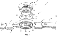
- brace for articulation 1 according to the present invention is observed.
- Said brace for articulation 1 includes a joint 2, a first rod 3 and a second rod 4.
- Said joint 2 is interposed between said first rod 3 and said second rod 4 and allows their articulation.
- Said joint 2 comprises a pair of toothed circular rings 21 and 22, arranged overlapped, each fixed by means of suitable screws 211 to one end of said first rod 3, interposed between them.
- Each circular ring 21 and 22 has a central through hole, for allowing the insertion of a fixing central pivot (not shown in the figure). In the figures the through hole 212 of the circular ring 21 is shown.
- the second rod 4 has a through hole at one end. Said second rod 4 is inserted between said circular rings 21 and 22, and said fixing central pivot also passes through said through hole. In this way, the second rod 4 can rotate between said circular rings 21 and 22 with respect to said first rod 3.
- buckles 31 and 41 are also arranged for securing the brace articulation 1 to the limb.
- Joint 2 also comprises a first and a second locking member 23 and 24, each having a first and a second portion respectively.
- Said first portion of said first and second locking member 23 and 24 comprises an upper relief, respectively indicated with 231 and 241, which are "V"-shaped, and a respective pivot 232 and 242, adapted to be inserted into two overlapped throats of the indentation of said circular rings 21 and 22.
- the lower portion of said first and second locking member 23 and 24 has two elastic facing arms, 233 and 234 (or 243 and 244), which identify an opening, through which fixing central pivot of joint 2 passes, which function will be better explained in the following.
- Joint 2 also includes adjustment means 25, interacting with said first and second locking member 23 and 24.
- Said adjustment means 25 comprise a first selector 26, capable to rotate around said fixing central pivot, which is provided below with a seat 261, in which said upper relief 231 of said locking member 23 is housed, and, at the top, with a adjustment relief 262.
- Said seat 261 is always "V"-shaped, as said upper relief 231 of said first locking member 23, with a greater size of it, for the reasons that will be better explained in the following.
- Said first selector 26 also provides an opening 263 on the surface having the shape of a circle arc.
- Said adjustment means 25 also comprise a second selector 27, which is also capable of rotating around said fixing central pivot, below provided with a seat 271, in which said upper relief 241 of said second locking member 24 is housed.
- a second selector 27 rotates with respect to said first selector 26
- said seat 271 slides along said opening 263 of said first selector 26.
- Said seat 271 is always "V"-shaped as said seat 261 of said locking member 23, and has a size greater than the respective upper relief 241, in which it is housed.
- Said second selector 27 also includes an adjustment relief 272.
- Said adjustment means 25 comprise also a knob 28, having suitable openings, to display the adjustment or the configurations of the joint 2, and one plate 29, interposed between said knob 28 and said second selector 27, in which adjustment graduated scales are provided, placed in correspondence of said openings of said knob 28.
- Said knob 28 has, in particular, one adjustment opening 281 having the form of a circle arc, in which said adjustment reliefs 262 and 272 can slide, which determines the rotation.
- the figures show the initial configuration of the brace for articulation 1, in which the rods 3 and 4 are aligned and the first and the second locking member 23 and 24 have the respective pivots 232 and 242 inserted in two throats of the two overlapped circular rings 21 and 22, such that the pivots of said first and second locking member 23 and 24 are in abutment with said rod 4, not allowing its movement, i.e. the rotation with respect to said first rod 3.
- first and the second selector 26 and 27, and the knob 28 are arranged so as to indicate that the brace for articulation 1 is arranged for the left joint (elbow or knee, for example), and the adjustment reliefs 262 and 272 are arranged at the bottom of the scale, i.e. at one end of said adjustment opening 281, indicating 0° of flexion (rods 3 and 4 aligned) and 0°of extension (rod 4 fixed).
- the first rod 3 would be aligned with the humerus, while the second rod 4 would be aligned with the ulna or with the radio.
- brace for articulation 1 is configured for a left limb, shows that knob 28 is arranged with respect to the adjustment elements 262 and 272, so that locking members 23 and 24 can be rotated only in direction A, as the adjustment reliefs 262 and 272 cannot slide in the opposite direction from said adjustment opening 281. Therefore, to move the locking member 24, the locking member 23 must be moved in said direction A before.
- the first selector 26 is rotated to the desired angle in the arrow A direction, reading on the scale shown on the plate 29, by acting on the adjustment relief 262.
- the seat 261 is shaped so as to move said upper relief 231 in the radial direction B, extracting the respective pivot 232 from the throats of the circular rings 21 and 22.
- arms 233 and 234 due to their elasticity, tend to exert a return force on the locking member 23, opposite to arrow B.
- pivot 232 is inserted again into two new throats of the circular rings 21 and 22. In this way, rod 4 (and therefore the limb) can rotate by a rotation angle identified between the pivot 232 of said first locking member 23 and the pivot 242 of said second locking member 24.
- the second locking member 24 can be rotated at most by the same angle which the first locking member 23 is rotated. In particular, by rotating said second locking member 24 by the same angle of said first locking member 23, rod 4 is fixed with respect to said rod 3 of said angle.
- knob 28 is rotated, so that the adjustment reliefs 262 and 272 are arranged in abutment to the other end of said adjustment opening 281, which determines the new end scale. Therefore, in this case, it will be possible to initially rotate said second locking member 24, for determining the flexion of the rod 4 with respect to rod 3, i.e. of the limb, and only subsequently to rotate said first locking member 23, to reduce the flexion angle or to fix the angle between said rod 3 and said rod 4. Furthermore, by turning said knob 28, the openings are arranged so as to indicate the limb (right or left) for which joint 2 is configured.
- the first rod 3 is aligned with the humerus and the second rod 4 with the ulna or with the radio.
Landscapes
- Health & Medical Sciences (AREA)
- Engineering & Computer Science (AREA)
- General Engineering & Computer Science (AREA)
- Vascular Medicine (AREA)
- Animal Behavior & Ethology (AREA)
- Orthopedic Medicine & Surgery (AREA)
- Biomedical Technology (AREA)
- Heart & Thoracic Surgery (AREA)
- Veterinary Medicine (AREA)
- Life Sciences & Earth Sciences (AREA)
- Nursing (AREA)
- General Health & Medical Sciences (AREA)
- Public Health (AREA)
- Mechanical Engineering (AREA)
- Orthopedics, Nursing, And Contraception (AREA)
- Stringed Musical Instruments (AREA)
- Pharmaceuticals Containing Other Organic And Inorganic Compounds (AREA)
Priority Applications (1)
| Application Number | Priority Date | Filing Date | Title |
|---|---|---|---|
| PL14425016T PL2769702T3 (pl) | 2013-02-21 | 2014-02-19 | Klamra na staw |
Applications Claiming Priority (1)
| Application Number | Priority Date | Filing Date | Title |
|---|---|---|---|
| IT000100A ITRM20130100A1 (it) | 2013-02-21 | 2013-02-21 | Tutore per articolazione. |
Publications (2)
| Publication Number | Publication Date |
|---|---|
| EP2769702A1 EP2769702A1 (en) | 2014-08-27 |
| EP2769702B1 true EP2769702B1 (en) | 2017-09-06 |
Family
ID=48184381
Family Applications (1)
| Application Number | Title | Priority Date | Filing Date |
|---|---|---|---|
| EP14425016.4A Active EP2769702B1 (en) | 2013-02-21 | 2014-02-19 | Brace for articulation |
Country Status (5)
| Country | Link |
|---|---|
| US (1) | US9458878B2 (pl) |
| EP (1) | EP2769702B1 (pl) |
| ES (1) | ES2648905T3 (pl) |
| IT (1) | ITRM20130100A1 (pl) |
| PL (1) | PL2769702T3 (pl) |
Families Citing this family (9)
| Publication number | Priority date | Publication date | Assignee | Title |
|---|---|---|---|---|
| US10427023B2 (en) * | 2016-04-15 | 2019-10-01 | Bsn Sports, Llc | Shoulder pads and method of manufacturing the same |
| DE102018105480A1 (de) * | 2018-03-09 | 2019-09-12 | Albrecht Gmbh | Orthese mit Anschlagstifthalter |
| CN109552672B (zh) * | 2018-11-12 | 2021-12-17 | 上海宇航系统工程研究所 | 一种硬限位角度可调的限位机构 |
| CN110507459B (zh) * | 2019-08-21 | 2021-09-28 | 江苏博润医疗集团有限公司 | 一种用于风湿病患者的防护装置 |
| CN111255999B (zh) * | 2020-01-17 | 2022-01-28 | 深圳市洲明科技股份有限公司 | 一种弧形调节锁 |
| US12121463B1 (en) | 2020-02-13 | 2024-10-22 | Preferred Prescription, Inc. | Knee/elbow brace |
| US11918500B1 (en) | 2020-03-31 | 2024-03-05 | Preferred Prescription, Inc. | Hinged knee brace with double upper strap arrangement |
| KR102430563B1 (ko) * | 2020-10-21 | 2022-08-08 | 조병우 | 관절 보조기 |
| CN112483818B (zh) * | 2020-11-17 | 2025-02-21 | 深圳市蓝禾技术有限公司 | 多挡调节结构及电子设备支架 |
Family Cites Families (42)
| Publication number | Priority date | Publication date | Assignee | Title |
|---|---|---|---|---|
| US2812961A (en) * | 1955-06-21 | 1957-11-12 | A J Hosmer Corp | Prosthetic locking hinge |
| US4463751A (en) * | 1982-12-27 | 1984-08-07 | Bledsoe Gary R | Stabilizing knee hinge |
| US4620532A (en) * | 1983-09-26 | 1986-11-04 | Lenox Hill Brace Shop, Inc. | Adjustment device for an articulated joint brace |
| US4540306A (en) * | 1983-10-19 | 1985-09-10 | Wang Chien Yuan | Positioning joint for folding ladders |
| KR900009120Y1 (ko) * | 1987-03-31 | 1990-09-29 | 주식회사 우경제작소 | 절첩식 사다리용 경첩 |
| US4846842A (en) * | 1987-06-25 | 1989-07-11 | Connolly & Mcmaster | Body joint rotation support device |
| US4817588A (en) * | 1987-07-01 | 1989-04-04 | Medical Technology, Inc. | Motion restraining knee brace |
| US5052379A (en) * | 1989-04-27 | 1991-10-01 | Soma Dynamics Corporation | Combination brace and wearable exercise apparatus for body joints |
| CH679910A5 (pl) * | 1989-05-30 | 1992-05-15 | Broeck Marc Vanden | |
| US5000169A (en) * | 1990-01-16 | 1991-03-19 | Clinitex Corporation | Adjustable flexion-extension hinge for hinged limb immobilizer |
| US4982732A (en) * | 1990-02-06 | 1991-01-08 | Orthopedic Technology, Inc. | Orthopedic rehabilitation knee brace |
| US5292303A (en) * | 1992-07-01 | 1994-03-08 | Smith & Nephew Donjoy, Inc. | Hinged orthopedic brace having an adjustable pivot range |
| EP0611093A3 (en) * | 1993-02-05 | 1994-08-31 | Stephen Hutchins | Knee brace |
| US5399154A (en) * | 1993-06-30 | 1995-03-21 | Empi, Inc. | Constant torque range-of-motion splint |
| US5409449A (en) * | 1993-07-09 | 1995-04-25 | Smith & Nephew Donjoy Inc. | Detent mechanism for a hinged orthopedic brace |
| US5437611A (en) * | 1993-12-01 | 1995-08-01 | Orthotic Rehabilitation Products, Inc. | Dynamic brace joint |
| US5421810A (en) * | 1994-04-14 | 1995-06-06 | Orthomerica Products, Inc. | Orthopedic hinge assembly for an orthopedic brace |
| US5460599A (en) * | 1994-05-26 | 1995-10-24 | Orthomerica Products, Inc. | Orthopedic hinge assembly for a leg brace |
| US5443444A (en) * | 1994-07-19 | 1995-08-22 | Professional Care Products Incorporated | Orthopaedic polycentric hinge |
| US5827208A (en) * | 1995-11-28 | 1998-10-27 | Breg, Inc, | Hinge for an orthopedic brace having a selectively positionable stop to limit rotation |
| US5814000A (en) * | 1996-07-12 | 1998-09-29 | Professional Products, Inc. | Adjustable joint brace |
| GB9619968D0 (en) * | 1996-09-25 | 1996-11-13 | Johnson & Johnson Professional | Hinge with locking means |
| US6080122A (en) * | 1998-08-24 | 2000-06-27 | Gulledge; Ronald E. | Motion restraining brace |
| US6527733B1 (en) * | 2000-02-22 | 2003-03-04 | Dj Orthopedics, Llc | Hinge assembly for an orthopedic knee brace and knee brace incorporating the hinge assembly |
| US6993808B1 (en) * | 2000-09-18 | 2006-02-07 | Lenjoy Medical Engineering, Inc. | Adjustable hinges for orthopedic splints |
| US6675546B2 (en) * | 2000-10-20 | 2004-01-13 | Total Structures, Inc. | Universal connector |
| CN1241526C (zh) * | 2000-11-15 | 2006-02-15 | 有限会社之攸美义肢制作所 | 人体矫正器 |
| US6623439B2 (en) * | 2001-08-31 | 2003-09-23 | Dj Orthopedics, Llc | Contoured knee brace frame |
| DE10207702C1 (de) * | 2002-02-22 | 2003-08-28 | Albrecht Gmbh | Einstellbare Gelenkorthese |
| US7235058B2 (en) * | 2002-09-11 | 2007-06-26 | Djo, Llc | Lockable hinge |
| US20040267179A1 (en) * | 2003-06-30 | 2004-12-30 | Max Lerman | Knee unloading orthotic device and method |
| US7037287B2 (en) * | 2003-09-29 | 2006-05-02 | Royce Medical Company | Adjustable ergonomic knee brace |
| US7534220B2 (en) * | 2003-09-29 | 2009-05-19 | Ossur Hf | Adjustable ergonomic brace |
| JP4098729B2 (ja) * | 2004-02-04 | 2008-06-11 | 医療法人北辰会 | 回転負荷設定手段を有する関節補装具回転ジョイント、該回転ジョイントを用いた関節補装具及び該関節補装具の製作方法 |
| US8277403B2 (en) * | 2005-01-12 | 2012-10-02 | Breg, Inc. | Support assembly for an orthopedic brace having a length-adjusting mechanism |
| US8273045B2 (en) * | 2005-01-12 | 2012-09-25 | Breg, Inc. | Method for fitting an orthopedic brace to the body |
| US7235059B2 (en) * | 2005-01-12 | 2007-06-26 | Breg, Inc. | Releasably locking hinge for an orthopedic brace having adjustable rotation limits |
| US7984531B2 (en) * | 2005-09-23 | 2011-07-26 | Restorative Care Of America Incorporated | Rachet hinge for a knee or elbow orthosis |
| US7485103B2 (en) * | 2006-04-13 | 2009-02-03 | Breg, Inc. | Rotational hinge assembly for a knee brace having an osteoarthritis treatment function |
| US7841999B2 (en) * | 2008-08-25 | 2010-11-30 | Ebi, Llc | Adjustable hinge for orthopedic brace |
| US7988653B2 (en) * | 2009-01-08 | 2011-08-02 | Breg, Inc. | Orthopedic elbow brace having a length-adjustable support assembly |
| US8591444B2 (en) * | 2010-06-25 | 2013-11-26 | Djo, Llc | Hinge for an orthopedic brace |
-
2013
- 2013-02-21 IT IT000100A patent/ITRM20130100A1/it unknown
-
2014
- 2014-02-18 US US14/182,828 patent/US9458878B2/en active Active
- 2014-02-19 PL PL14425016T patent/PL2769702T3/pl unknown
- 2014-02-19 ES ES14425016.4T patent/ES2648905T3/es active Active
- 2014-02-19 EP EP14425016.4A patent/EP2769702B1/en active Active
Non-Patent Citations (1)
| Title |
|---|
| None * |
Also Published As
| Publication number | Publication date |
|---|---|
| ITRM20130100A1 (it) | 2014-08-22 |
| US20140234016A1 (en) | 2014-08-21 |
| ES2648905T3 (es) | 2018-01-08 |
| US9458878B2 (en) | 2016-10-04 |
| PL2769702T3 (pl) | 2018-01-31 |
| EP2769702A1 (en) | 2014-08-27 |
Similar Documents
| Publication | Publication Date | Title |
|---|---|---|
| EP2769702B1 (en) | Brace for articulation | |
| AU2016296482B2 (en) | Variable force exoskeleton hip joint | |
| US6402711B1 (en) | Knee brace operating hinge | |
| JP2001520080A (ja) | 関節装具のヒンジ | |
| US8728018B2 (en) | Post operative hinge brace | |
| AU2004277944B2 (en) | Adjustable ergonomic knee brace | |
| EP2585008B1 (en) | A hinge for an orthopedic brace | |
| AU2015301134B2 (en) | Knee brace with adjustable strut length and dynamic strut lengthening | |
| US20130331754A1 (en) | Hinge for an orthopedic device | |
| US8187211B2 (en) | Pivot mechanism for a joint support | |
| JP6533851B2 (ja) | 計時器用機構 | |
| CN111789433B (zh) | 可穿戴座椅的就坐支撑装置 | |
| US11187262B2 (en) | Hinge having a rotation-stop lock | |
| EP1475060B2 (en) | Articulated joint for postoperative brace | |
| EP1086670A2 (en) | Adjustable orthopaedic brace | |
| KR102466581B1 (ko) | 무릎/팔꿈치 관절 어시스트 장치 | |
| EP1088534A2 (en) | Range of motion orthopaedic joint brace with a linearly actuated stop | |
| EP4233749B1 (en) | External fixation strut | |
| WO2002002037A1 (en) | Orthopaedic brace having an axially settable range of motion hinge | |
| EP3797841A1 (en) | An orthopaedic orthosis for carrying out pronosupination exercises with adjustable range of motion | |
| US20030091382A1 (en) | Non-restricting knee joint | |
| EP3782590B1 (en) | Joint for hinged braces | |
| EP3808318A1 (en) | Articulated joint for orthopaedic orthoses or braces | |
| JP6621391B2 (ja) | 装具の継手装置 | |
| WO2002002036A1 (en) | Range of motion orthopaedic joint brace with a linearly actuated stop |
Legal Events
| Date | Code | Title | Description |
|---|---|---|---|
| PUAI | Public reference made under article 153(3) epc to a published international application that has entered the european phase |
Free format text: ORIGINAL CODE: 0009012 |
|
| 17P | Request for examination filed |
Effective date: 20140219 |
|
| AK | Designated contracting states |
Kind code of ref document: A1 Designated state(s): AL AT BE BG CH CY CZ DE DK EE ES FI FR GB GR HR HU IE IS IT LI LT LU LV MC MK MT NL NO PL PT RO RS SE SI SK SM TR |
|
| AX | Request for extension of the european patent |
Extension state: BA ME |
|
| RBV | Designated contracting states (corrected) |
Designated state(s): AL AT BE BG CH CY CZ DE DK EE ES FI FR GB GR HR HU IE IS IT LI LT LU LV MC MK MT NL NO PL PT RO RS SE SI SK SM TR |
|
| R17P | Request for examination filed (corrected) |
Effective date: 20150219 |
|
| GRAP | Despatch of communication of intention to grant a patent |
Free format text: ORIGINAL CODE: EPIDOSNIGR1 |
|
| RIC1 | Information provided on ipc code assigned before grant |
Ipc: A61F 5/01 20060101AFI20170327BHEP |
|
| INTG | Intention to grant announced |
Effective date: 20170503 |
|
| GRAS | Grant fee paid |
Free format text: ORIGINAL CODE: EPIDOSNIGR3 |
|
| GRAA | (expected) grant |
Free format text: ORIGINAL CODE: 0009210 |
|
| AK | Designated contracting states |
Kind code of ref document: B1 Designated state(s): AL AT BE BG CH CY CZ DE DK EE ES FI FR GB GR HR HU IE IS IT LI LT LU LV MC MK MT NL NO PL PT RO RS SE SI SK SM TR |
|
| REG | Reference to a national code |
Ref country code: GB Ref legal event code: FG4D |
|
| REG | Reference to a national code |
Ref country code: CH Ref legal event code: EP Ref country code: AT Ref legal event code: REF Ref document number: 925061 Country of ref document: AT Kind code of ref document: T Effective date: 20170915 |
|
| REG | Reference to a national code |
Ref country code: IE Ref legal event code: FG4D |
|
| REG | Reference to a national code |
Ref country code: DE Ref legal event code: R096 Ref document number: 602014014125 Country of ref document: DE |
|
| REG | Reference to a national code |
Ref country code: ES Ref legal event code: FG2A Ref document number: 2648905 Country of ref document: ES Kind code of ref document: T3 Effective date: 20180108 |
|
| REG | Reference to a national code |
Ref country code: NL Ref legal event code: MP Effective date: 20170906 |
|
| REG | Reference to a national code |
Ref country code: LT Ref legal event code: MG4D |
|
| PG25 | Lapsed in a contracting state [announced via postgrant information from national office to epo] |
Ref country code: SE Free format text: LAPSE BECAUSE OF FAILURE TO SUBMIT A TRANSLATION OF THE DESCRIPTION OR TO PAY THE FEE WITHIN THE PRESCRIBED TIME-LIMIT Effective date: 20170906 Ref country code: FI Free format text: LAPSE BECAUSE OF FAILURE TO SUBMIT A TRANSLATION OF THE DESCRIPTION OR TO PAY THE FEE WITHIN THE PRESCRIBED TIME-LIMIT Effective date: 20170906 Ref country code: NO Free format text: LAPSE BECAUSE OF FAILURE TO SUBMIT A TRANSLATION OF THE DESCRIPTION OR TO PAY THE FEE WITHIN THE PRESCRIBED TIME-LIMIT Effective date: 20171206 Ref country code: LT Free format text: LAPSE BECAUSE OF FAILURE TO SUBMIT A TRANSLATION OF THE DESCRIPTION OR TO PAY THE FEE WITHIN THE PRESCRIBED TIME-LIMIT Effective date: 20170906 Ref country code: HR Free format text: LAPSE BECAUSE OF FAILURE TO SUBMIT A TRANSLATION OF THE DESCRIPTION OR TO PAY THE FEE WITHIN THE PRESCRIBED TIME-LIMIT Effective date: 20170906 |
|
| REG | Reference to a national code |
Ref country code: AT Ref legal event code: MK05 Ref document number: 925061 Country of ref document: AT Kind code of ref document: T Effective date: 20170906 |
|
| PG25 | Lapsed in a contracting state [announced via postgrant information from national office to epo] |
Ref country code: RS Free format text: LAPSE BECAUSE OF FAILURE TO SUBMIT A TRANSLATION OF THE DESCRIPTION OR TO PAY THE FEE WITHIN THE PRESCRIBED TIME-LIMIT Effective date: 20170906 Ref country code: BG Free format text: LAPSE BECAUSE OF FAILURE TO SUBMIT A TRANSLATION OF THE DESCRIPTION OR TO PAY THE FEE WITHIN THE PRESCRIBED TIME-LIMIT Effective date: 20171206 Ref country code: GR Free format text: LAPSE BECAUSE OF FAILURE TO SUBMIT A TRANSLATION OF THE DESCRIPTION OR TO PAY THE FEE WITHIN THE PRESCRIBED TIME-LIMIT Effective date: 20171207 Ref country code: LV Free format text: LAPSE BECAUSE OF FAILURE TO SUBMIT A TRANSLATION OF THE DESCRIPTION OR TO PAY THE FEE WITHIN THE PRESCRIBED TIME-LIMIT Effective date: 20170906 |
|
| PG25 | Lapsed in a contracting state [announced via postgrant information from national office to epo] |
Ref country code: NL Free format text: LAPSE BECAUSE OF FAILURE TO SUBMIT A TRANSLATION OF THE DESCRIPTION OR TO PAY THE FEE WITHIN THE PRESCRIBED TIME-LIMIT Effective date: 20170906 |
|
| PG25 | Lapsed in a contracting state [announced via postgrant information from national office to epo] |
Ref country code: CZ Free format text: LAPSE BECAUSE OF FAILURE TO SUBMIT A TRANSLATION OF THE DESCRIPTION OR TO PAY THE FEE WITHIN THE PRESCRIBED TIME-LIMIT Effective date: 20170906 Ref country code: RO Free format text: LAPSE BECAUSE OF FAILURE TO SUBMIT A TRANSLATION OF THE DESCRIPTION OR TO PAY THE FEE WITHIN THE PRESCRIBED TIME-LIMIT Effective date: 20170906 |
|
| PG25 | Lapsed in a contracting state [announced via postgrant information from national office to epo] |
Ref country code: IS Free format text: LAPSE BECAUSE OF FAILURE TO SUBMIT A TRANSLATION OF THE DESCRIPTION OR TO PAY THE FEE WITHIN THE PRESCRIBED TIME-LIMIT Effective date: 20180106 Ref country code: SM Free format text: LAPSE BECAUSE OF FAILURE TO SUBMIT A TRANSLATION OF THE DESCRIPTION OR TO PAY THE FEE WITHIN THE PRESCRIBED TIME-LIMIT Effective date: 20170906 Ref country code: SK Free format text: LAPSE BECAUSE OF FAILURE TO SUBMIT A TRANSLATION OF THE DESCRIPTION OR TO PAY THE FEE WITHIN THE PRESCRIBED TIME-LIMIT Effective date: 20170906 Ref country code: AT Free format text: LAPSE BECAUSE OF FAILURE TO SUBMIT A TRANSLATION OF THE DESCRIPTION OR TO PAY THE FEE WITHIN THE PRESCRIBED TIME-LIMIT Effective date: 20170906 Ref country code: EE Free format text: LAPSE BECAUSE OF FAILURE TO SUBMIT A TRANSLATION OF THE DESCRIPTION OR TO PAY THE FEE WITHIN THE PRESCRIBED TIME-LIMIT Effective date: 20170906 |
|
| REG | Reference to a national code |
Ref country code: DE Ref legal event code: R097 Ref document number: 602014014125 Country of ref document: DE |
|
| PLBE | No opposition filed within time limit |
Free format text: ORIGINAL CODE: 0009261 |
|
| STAA | Information on the status of an ep patent application or granted ep patent |
Free format text: STATUS: NO OPPOSITION FILED WITHIN TIME LIMIT |
|
| PG25 | Lapsed in a contracting state [announced via postgrant information from national office to epo] |
Ref country code: DK Free format text: LAPSE BECAUSE OF FAILURE TO SUBMIT A TRANSLATION OF THE DESCRIPTION OR TO PAY THE FEE WITHIN THE PRESCRIBED TIME-LIMIT Effective date: 20170906 |
|
| 26N | No opposition filed |
Effective date: 20180607 |
|
| PG25 | Lapsed in a contracting state [announced via postgrant information from national office to epo] |
Ref country code: SI Free format text: LAPSE BECAUSE OF FAILURE TO SUBMIT A TRANSLATION OF THE DESCRIPTION OR TO PAY THE FEE WITHIN THE PRESCRIBED TIME-LIMIT Effective date: 20170906 |
|
| REG | Reference to a national code |
Ref country code: DE Ref legal event code: R119 Ref document number: 602014014125 Country of ref document: DE |
|
| PG25 | Lapsed in a contracting state [announced via postgrant information from national office to epo] |
Ref country code: MC Free format text: LAPSE BECAUSE OF FAILURE TO SUBMIT A TRANSLATION OF THE DESCRIPTION OR TO PAY THE FEE WITHIN THE PRESCRIBED TIME-LIMIT Effective date: 20170906 |
|
| REG | Reference to a national code |
Ref country code: IE Ref legal event code: MM4A |
|
| REG | Reference to a national code |
Ref country code: BE Ref legal event code: MM Effective date: 20180228 |
|
| PG25 | Lapsed in a contracting state [announced via postgrant information from national office to epo] |
Ref country code: LU Free format text: LAPSE BECAUSE OF NON-PAYMENT OF DUE FEES Effective date: 20180219 |
|
| REG | Reference to a national code |
Ref country code: FR Ref legal event code: ST Effective date: 20181031 |
|
| PG25 | Lapsed in a contracting state [announced via postgrant information from national office to epo] |
Ref country code: IE Free format text: LAPSE BECAUSE OF NON-PAYMENT OF DUE FEES Effective date: 20180219 Ref country code: DE Free format text: LAPSE BECAUSE OF NON-PAYMENT OF DUE FEES Effective date: 20180901 |
|
| PG25 | Lapsed in a contracting state [announced via postgrant information from national office to epo] |
Ref country code: BE Free format text: LAPSE BECAUSE OF NON-PAYMENT OF DUE FEES Effective date: 20180228 Ref country code: FR Free format text: LAPSE BECAUSE OF NON-PAYMENT OF DUE FEES Effective date: 20180228 |
|
| PGFP | Annual fee paid to national office [announced via postgrant information from national office to epo] |
Ref country code: ES Payment date: 20190301 Year of fee payment: 6 Ref country code: CH Payment date: 20190228 Year of fee payment: 6 Ref country code: GB Payment date: 20190220 Year of fee payment: 6 Ref country code: PL Payment date: 20190219 Year of fee payment: 6 |
|
| PG25 | Lapsed in a contracting state [announced via postgrant information from national office to epo] |
Ref country code: MT Free format text: LAPSE BECAUSE OF NON-PAYMENT OF DUE FEES Effective date: 20180219 |
|
| PG25 | Lapsed in a contracting state [announced via postgrant information from national office to epo] |
Ref country code: TR Free format text: LAPSE BECAUSE OF FAILURE TO SUBMIT A TRANSLATION OF THE DESCRIPTION OR TO PAY THE FEE WITHIN THE PRESCRIBED TIME-LIMIT Effective date: 20170906 |
|
| PG25 | Lapsed in a contracting state [announced via postgrant information from national office to epo] |
Ref country code: HU Free format text: LAPSE BECAUSE OF FAILURE TO SUBMIT A TRANSLATION OF THE DESCRIPTION OR TO PAY THE FEE WITHIN THE PRESCRIBED TIME-LIMIT; INVALID AB INITIO Effective date: 20140219 Ref country code: PT Free format text: LAPSE BECAUSE OF FAILURE TO SUBMIT A TRANSLATION OF THE DESCRIPTION OR TO PAY THE FEE WITHIN THE PRESCRIBED TIME-LIMIT Effective date: 20170906 |
|
| PG25 | Lapsed in a contracting state [announced via postgrant information from national office to epo] |
Ref country code: CY Free format text: LAPSE BECAUSE OF FAILURE TO SUBMIT A TRANSLATION OF THE DESCRIPTION OR TO PAY THE FEE WITHIN THE PRESCRIBED TIME-LIMIT Effective date: 20170906 Ref country code: MK Free format text: LAPSE BECAUSE OF NON-PAYMENT OF DUE FEES Effective date: 20170906 |
|
| PG25 | Lapsed in a contracting state [announced via postgrant information from national office to epo] |
Ref country code: AL Free format text: LAPSE BECAUSE OF FAILURE TO SUBMIT A TRANSLATION OF THE DESCRIPTION OR TO PAY THE FEE WITHIN THE PRESCRIBED TIME-LIMIT Effective date: 20170906 |
|
| REG | Reference to a national code |
Ref country code: CH Ref legal event code: PL |
|
| GBPC | Gb: european patent ceased through non-payment of renewal fee |
Effective date: 20200219 |
|
| PG25 | Lapsed in a contracting state [announced via postgrant information from national office to epo] |
Ref country code: CH Free format text: LAPSE BECAUSE OF NON-PAYMENT OF DUE FEES Effective date: 20200229 Ref country code: LI Free format text: LAPSE BECAUSE OF NON-PAYMENT OF DUE FEES Effective date: 20200229 |
|
| PG25 | Lapsed in a contracting state [announced via postgrant information from national office to epo] |
Ref country code: GB Free format text: LAPSE BECAUSE OF NON-PAYMENT OF DUE FEES Effective date: 20200219 |
|
| REG | Reference to a national code |
Ref country code: ES Ref legal event code: FD2A Effective date: 20210705 |
|
| PG25 | Lapsed in a contracting state [announced via postgrant information from national office to epo] |
Ref country code: ES Free format text: LAPSE BECAUSE OF NON-PAYMENT OF DUE FEES Effective date: 20200220 |
|
| PG25 | Lapsed in a contracting state [announced via postgrant information from national office to epo] |
Ref country code: PL Free format text: LAPSE BECAUSE OF NON-PAYMENT OF DUE FEES Effective date: 20200219 |
|
| PGFP | Annual fee paid to national office [announced via postgrant information from national office to epo] |
Ref country code: IT Payment date: 20260212 Year of fee payment: 13 |