EP2767680A1 - Camshaft support structure - Google Patents
Camshaft support structure Download PDFInfo
- Publication number
- EP2767680A1 EP2767680A1 EP11873837.6A EP11873837A EP2767680A1 EP 2767680 A1 EP2767680 A1 EP 2767680A1 EP 11873837 A EP11873837 A EP 11873837A EP 2767680 A1 EP2767680 A1 EP 2767680A1
- Authority
- EP
- European Patent Office
- Prior art keywords
- camshaft
- support bases
- cylinder head
- support
- internal combustion
- Prior art date
- Legal status (The legal status is an assumption and is not a legal conclusion. Google has not performed a legal analysis and makes no representation as to the accuracy of the status listed.)
- Withdrawn
Links
- 238000002485 combustion reaction Methods 0.000 claims abstract description 38
- 239000000463 material Substances 0.000 claims description 5
- 229910000838 Al alloy Inorganic materials 0.000 description 5
- 230000006866 deterioration Effects 0.000 description 4
- 239000010935 stainless steel Substances 0.000 description 4
- 229910001220 stainless steel Inorganic materials 0.000 description 4
- 230000002542 deteriorative effect Effects 0.000 description 2
- 230000006698 induction Effects 0.000 description 1
Images
Classifications
-
- F—MECHANICAL ENGINEERING; LIGHTING; HEATING; WEAPONS; BLASTING
- F01—MACHINES OR ENGINES IN GENERAL; ENGINE PLANTS IN GENERAL; STEAM ENGINES
- F01L—CYCLICALLY OPERATING VALVES FOR MACHINES OR ENGINES
- F01L1/00—Valve-gear or valve arrangements, e.g. lift-valve gear
- F01L1/46—Component parts, details, or accessories, not provided for in preceding subgroups
-
- F—MECHANICAL ENGINEERING; LIGHTING; HEATING; WEAPONS; BLASTING
- F01—MACHINES OR ENGINES IN GENERAL; ENGINE PLANTS IN GENERAL; STEAM ENGINES
- F01L—CYCLICALLY OPERATING VALVES FOR MACHINES OR ENGINES
- F01L1/00—Valve-gear or valve arrangements, e.g. lift-valve gear
- F01L1/02—Valve drive
- F01L1/04—Valve drive by means of cams, camshafts, cam discs, eccentrics or the like
- F01L1/047—Camshafts
- F01L1/053—Camshafts overhead type
-
- F—MECHANICAL ENGINEERING; LIGHTING; HEATING; WEAPONS; BLASTING
- F01—MACHINES OR ENGINES IN GENERAL; ENGINE PLANTS IN GENERAL; STEAM ENGINES
- F01L—CYCLICALLY OPERATING VALVES FOR MACHINES OR ENGINES
- F01L1/00—Valve-gear or valve arrangements, e.g. lift-valve gear
- F01L1/02—Valve drive
- F01L1/04—Valve drive by means of cams, camshafts, cam discs, eccentrics or the like
- F01L1/047—Camshafts
- F01L2001/0476—Camshaft bearings
-
- F—MECHANICAL ENGINEERING; LIGHTING; HEATING; WEAPONS; BLASTING
- F01—MACHINES OR ENGINES IN GENERAL; ENGINE PLANTS IN GENERAL; STEAM ENGINES
- F01L—CYCLICALLY OPERATING VALVES FOR MACHINES OR ENGINES
- F01L1/00—Valve-gear or valve arrangements, e.g. lift-valve gear
- F01L1/02—Valve drive
- F01L1/04—Valve drive by means of cams, camshafts, cam discs, eccentrics or the like
- F01L1/047—Camshafts
- F01L1/053—Camshafts overhead type
- F01L2001/0537—Double overhead camshafts [DOHC]
Definitions
- the present invention relates to a camshaft support structure that includes support bases, which are mounted on the cylinder head of an internal combustion engine and support camshafts to be freely rotational.
- the weight of the internal combustion engine is reduced as compared to a structure in which an outer frame for connecting the support bases is provided, as in a ladder-frame camshaft housing, by the weight corresponding to the outer frame.
- the temperature of the cylinder head is increased by receiving heat of exhaust gas, causing the cylinder head to be thermally deformed. Since the support bases are arranged to abut against the cylinder head, the support bases are thermally deformed by receiving heat from the cylinder head. This deteriorates alignment of bearing portions, which are formed in the support bases and support the camshafts. As a result, problems may arise such as an increase in rotational sliding resistance of the camshafts.
- camshaft support structure that favorably reduces deterioration in the alignment of bearing portions of support bases, which support camshafts, due to engine operation.
- the bearing portions of the support bases mounted on the cylinder head of the internal combustion engine support the camshaft to be freely rotational. Since the support bases are arranged apart from one another in the axial direction of the camshaft, the contact area between the support bases and the cylinder head is reduced as compared to the structure with an outer frame for connecting the support bases, such as a ladder-frame camshaft housing. This reduces the amount of heat received from the cylinder head, thus reducing thermal deformation of the support bases caused by the received heat.
- the rod is assembled to the cylinder head together with the support bases in a state in which the rod is inserted in the through holes.
- the cylinder head is assembled to the cylinder block with head bolts.
- the top surface of the cylinder head is slightly distorted from a flat state due to the axial tightening force of the head bolts. The rod is thus maintained in a state pressed by the inner walls of the through holes, and secured to the support bases.
- the structure thus favorably reduces deterioration in the alignment of the bearing portions of the support bases, which support the camshaft, due to engine operation.
- the rod is preferably made of material having higher rigidity than the support bases. According to this embodiment, thermal deformation of the support bases is reduced in an appropriate manner.
- the rod may be made of stainless-steel, which has higher rigidity than the aluminum alloy.
- each support base preferably includes a receiving member, which is mounted on the cylinder head and receives the camshaft, and a cap member, which is mounted on a top surface of the receiving member and forms the bearing portion together with the receiving member.
- the through hole is preferably formed in the receiving member.
- the thermal deformation of the cylinder head is thus greater in the region closer to the exhaust camshaft.
- the through holes in which the rod is inserted are formed closer to the exhaust camshaft than to the intake camshaft. That is, the rod is arranged close to the region of the receiving members of the support bases where the amount of heat received from the cylinder head is great and the degree of thermal deformation is great. The region of the support bases in the vicinity of the exhaust camshaft where the amount of heat received from the cylinder head is great is thus restricted from being thermally deformed in an appropriate manner.
- the thermal deformation amount of the support bases caused by heat received from the cylinder head is great. Furthermore, in the internal combustion engine provided with a forced-induction device, since the pressure in the cylinders is higher than that without the forced-induction device, the cylinder head is significantly deformed by fluctuation of the pressure in the cylinders of the internal combustion engine. As a result, the deformation amount of the support bases mounted on the cylinder head is increased.
- a camshaft support structure of a double overhead camshaft (DOHC) inline 4-cylinder internal combustion engine according to one embodiment of the present invention will now be described with reference to Figs. 1 to 3 .
- the internal combustion engine of the present embodiment is provided with an exhaust driven forced-induction device.
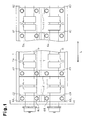
- Fig. 1 shows a planar structure of an internal combustion engine as viewed from above an exhaust camshaft and an intake camshaft.
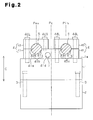
- Fig. 2 shows a cross-sectional structure of the internal combustion engine taken along line A-A of Fig. 1 .
- a cylinder head 1 which is provided with a valve mechanism including exhaust valves and intake valves, is provided on the top surface of a cylinder block 2 as shown in Fig. 2 .
- the cylinder block 2 and the cylinder head 1 are tightened with head bolts 3 in a known manner (see Figs. 2 and 3 ).
- An exhaust camshaft 5 provided with exhaust cams 51 for opening and closing the exhaust valves and an intake camshaft 6 provided with intake cams 61 for opening and closing the intake valves are arranged on a top surface 1 a of the cylinder head 1 to be parallel to each other. More specifically, five support bases 4 for supporting the camshafts 5, 6 to be freely rotational are mounted on the top surface 1 a of the cylinder head 1. Only one of the support bases 4 is shown in Fig. 2 .
- the support bases 4 are arranged apart from one another in an axial direction L of the camshafts 5, 6 as shown in Fig. 1 . More specifically, the support bases 4 are arranged to be perpendicular to the axial direction L of the camshafts 5, 6.
- Each of the support bases 4 includes a receiving member 41 located on the top surface 1 a of the cylinder head 1, and an exhaust side cap member 42 and an intake side cap member 43, which are located on the top surface of the receiving member 41 as shown in Fig. 2 .
- Semi-circular lower recesses 41 b, 41 c are formed on the top surface of each receiving member 41 at positions corresponding to the camshafts 5, 6.
- a semicircular upper recess 42b is formed on the bottom surface of each exhaust side cap member 42 at a position corresponding to the associated lower recess 41 b.
- Each lower recess 41 b and the associated upper recess 42b form a circular bearing portion 45b, which supports one of cam journals 5a of the exhaust camshaft 5 (see Fig. 1 ).
- each intake side cap member 43 Furthermore, a semicircular upper recess 43c is formed on the bottom surface of each intake side cap member 43 at a position corresponding to the associated lower recess 41 c.
- Each lower recess 41c and the associated upper recess 43c form a circular bearing portion 45c, which supports one of cam journals 6a of the intake camshaft 6 (see Fig. 1 ).
- each exhaust side cap member 42 and the associated receiving member 41 are formed in an axial direction C of the cylinders with the exhaust camshaft 5 located in between.
- the receiving member 41 and the exhaust side cap member 42 are tightened to the cylinder head 1 with bolts 44L, 44S inserted in the bolt holes.
- each intake side cap member 43 and the associated receiving member 41 are coupled to the cylinder head 1 with other bolts 44L in the same manner as each exhaust side cap member 42 and the associated receiving member 41.
- the cylinder head 1 In a state in which the support bases 4 are mounted on the cylinder head 1 with the bolts 44L, 44S, the cylinder head 1 is assembled to the cylinder block 2 with the head bolts 3.
- the cylinder head 1, the cylinder block 2, and the support bases 4 are all made of an aluminum alloy.
- a through hole 41 d which extends in the axial direction L of the camshafts 5, 6, is formed in each receiving member 41 as shown in Fig. 2 .
- Each through hole 41 d is formed at a position closer to a center position Pex of the exhaust camshaft 5 than to a middle position Pc between the center position Pex of the exhaust camshaft 5 and a center position Pin of the intake camshaft 6 in a direction perpendicular to the axial direction L of the camshafts 5, 6.
- the through holes 41 d are formed closer to the exhaust camshaft 5 than to the intake camshaft 6.
- a rod 7 made of stainless-steel is inserted in the through holes 41 d. That is, the rod 7 is made of material having higher rigidity than the support bases 4.
- the outer diameter of the rod 7 is slightly smaller than the inner diameter of the through holes 41 d.
- the bolts 44S located closer to the rod 7 than to the exhaust camshaft 5 are shorter than the other bolts 44L so as not to interfere with the rod 7.
- the camshafts 5, 6 are supported to be freely rotational by the bearing portions 45b, 45c of the five support bases 4 mounted on the cylinder head 1. Since the support bases 4 are located separate from one another in the axial direction L of the camshafts 5, 6, the contact area between the support bases 4 and the cylinder head 1 is reduced as compared to a case in which an outer frame for connecting the support bases is provided, as in a ladder-frame camshaft housing. The amount of heat received from the cylinder head 1 is thus reduced, which reduces thermal deformation of the support bases 4 caused by receiving heat.
- the temperature of exhaust gas is increased as compared to the internal combustion engine without a forced-induction device.
- This increases the thermal deformation amount of the support bases 4 caused by receiving heat from the cylinder head 1.
- the cylinder head 1 is deformed significantly as the pressure in the cylinders of the internal combustion engine fluctuates. The deformation amount of the support bases 4 mounted on the cylinder head 1 is consequently increased.
- the alignment of the bearing portions 45b, 45c in the support bases 4 is likely to deteriorate due to engine operation although with the camshaft support structure of the present embodiment that does not include the outer frame for the support bases 4.
- the support bases 4 are favorably restricted from being thermally deformed due to heat received from the cylinder head 1.
- the through holes 41d in which the rod 7 is inserted are formed at positions closer to the exhaust camshaft 5 than to the intake camshaft 6. That is, the rod 7 is arranged in the vicinity of the regions in the receiving members 41 of the support bases 4 where the amount of heat received from the cylinder head 1 is great and the degree of thermal deformation is great. Thermal deformation of the receiving members 41 in the vicinity of the exhaust camshaft 5 is thus reduced in an appropriate manner.
- the rod 7 is assembled to the cylinder head 1 together with the support bases 4 in a state in which the rod 7 is inserted in the through holes 41 d.
- the cylinder head 1 is further assembled to the cylinder block 2 with the head bolts 3 in a state in which the support bases 4 and the rod 7 are assembled to the cylinder head 1.
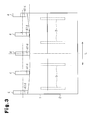
- the top surface 1 a of the cylinder head 1 is slightly distorted from a flat state due to the axial tightening force of the head bolts 3 as shown in Fig. 3 .
- the rod 7 is thus maintained in a state pressed by the inner walls of the through holes 41 d, and secured to the support bases 4.
- the distortion of the top surface 1 a of the cylinder head 1 is exaggerated and the rod 7 is omitted in Fig. 3 .
- the camshaft support structure of the present embodiment as described above has the following advantages.
- camshaft support structure of the present invention is not limited to the structure illustrated in the above described embodiment, but may be modified as follows.
- the present invention is applied to an internal combustion engine provided with an exhaust driven forced-induction device, that is, a turbocharger.
- the present invention may, however, be applied to an internal combustion engine provided with an engine driven forced-induction device, or a supercharger.
- the present invention is applied to an internal combustion engine provided with a forced-induction device.
- the present invention is not only applied to an internal combustion engine provided with a forced-induction device, but may be applied to an internal combustion engine without a forced-induction device.
- the alignment of the bearing portions of the support bases is favorably restricted from deteriorating due to engine operation in the same manner as the above-described embodiment.
- the through holes 41d be formed closer to the exhaust camshaft 5 than to the intake camshaft 6 to prevent thermal deformation of the receiving members 41 in the vicinity of the exhaust camshaft 5 where the amount of heat received from the cylinder head 1 is great.
- the present invention is not limited to this, but through holes may be formed at, for example, the middle position Pc between the exhaust camshaft 5 and the intake camshaft 6. In this case also, thermal deformation of the receiving members is restricted to some extent.
- one through hole 41d is formed in each of the support bases 4.
- two or more through holes may be formed in each of the support bases 4, and two or more rods may be provided corresponding to the number of the through holes. This further reduces thermal deformation of the support bases.
- the rod 7 made of stainless-steel is illustrated in the above-described embodiment, but the rod may be made of any material that has higher rigidity than the support bases.
Landscapes
- Engineering & Computer Science (AREA)
- Mechanical Engineering (AREA)
- General Engineering & Computer Science (AREA)
- Valve-Gear Or Valve Arrangements (AREA)
- Cylinder Crankcases Of Internal Combustion Engines (AREA)
Abstract
Description
- The present invention relates to a camshaft support structure that includes support bases, which are mounted on the cylinder head of an internal combustion engine and support camshafts to be freely rotational.
- Conventionally, this type of camshaft support structure has been proposed in, for example,
Patent Document 1. According to the camshaft support structure disclosed inPatent Document 1, the support bases, which support the camshafts to be freely rotational, are provided apart from one another in the axial direction of the camshafts. - With this structure, the weight of the internal combustion engine is reduced as compared to a structure in which an outer frame for connecting the support bases is provided, as in a ladder-frame camshaft housing, by the weight corresponding to the outer frame.
-
- Patent Documents
- Patent Document 1: Japanese Laid-Open Patent Publication No.
2010-209796 - When an engine is operated, the temperature of the cylinder head is increased by receiving heat of exhaust gas, causing the cylinder head to be thermally deformed. Since the support bases are arranged to abut against the cylinder head, the support bases are thermally deformed by receiving heat from the cylinder head. This deteriorates alignment of bearing portions, which are formed in the support bases and support the camshafts. As a result, problems may arise such as an increase in rotational sliding resistance of the camshafts.
- According to the structure disclosed in
Patent Document 1, the amount of heat that the support bases receive from the cylinder head is reduced as compared to the structure with the ladder-frame camshaft housing by the amount corresponding to the outer frame. The thermal deformation amount of the support bases is thus reduced to some extent. If, however, the invention is applied to an internal combustion engine in which the exhaust gas temperature is further increased such as an internal combustion engine provided with a forced-induction device, the amount of heat that the support bases receive from the cylinder head is further increased. In this case, there are limitations in favorably reducing deterioration in the alignment of the bearing portions of the support bases. - Accordingly, it is an objective of the present invention to provide a camshaft support structure that favorably reduces deterioration in the alignment of bearing portions of support bases, which support camshafts, due to engine operation.
- Means for solving the above issues and advantages thereof will now be discussed.
- To achieve the foregoing objective and in accordance with one aspect of the present invention, a camshaft support structure mounted on a cylinder head of an internal combustion engine includes support bases for supporting a camshaft to be freely rotational. The support bases are arranged apart from one another in an axial direction of the camshaft. Each support base has a bearing portion, which supports the camshaft, and a through hole, which extends in the axial direction of the camshaft. The through holes receive a rod, which restricts the bearing portions from being displaced from an arrangement position at which the bearing portions are located when the internal combustion engine is stopped and cold.
- With this structure, the bearing portions of the support bases mounted on the cylinder head of the internal combustion engine support the camshaft to be freely rotational. Since the support bases are arranged apart from one another in the axial direction of the camshaft, the contact area between the support bases and the cylinder head is reduced as compared to the structure with an outer frame for connecting the support bases, such as a ladder-frame camshaft housing. This reduces the amount of heat received from the cylinder head, thus reducing thermal deformation of the support bases caused by the received heat.
- Furthermore, with this structure, since the rod is inserted in the through holes formed in the support bases, the support bases are restricted from being thermally deformed by the heat received from the cylinder head.
- The rod is assembled to the cylinder head together with the support bases in a state in which the rod is inserted in the through holes. The cylinder head is assembled to the cylinder block with head bolts. The top surface of the cylinder head is slightly distorted from a flat state due to the axial tightening force of the head bolts. The rod is thus maintained in a state pressed by the inner walls of the through holes, and secured to the support bases.
- The structure thus favorably reduces deterioration in the alignment of the bearing portions of the support bases, which support the camshaft, due to engine operation. The rod is preferably made of material having higher rigidity than the support bases. According to this embodiment, thermal deformation of the support bases is reduced in an appropriate manner. In a case in which the support bases are made of aluminum alloy, for example, the rod may be made of stainless-steel, which has higher rigidity than the aluminum alloy.
- As a specific structure of the support bases, each support base preferably includes a receiving member, which is mounted on the cylinder head and receives the camshaft, and a cap member, which is mounted on a top surface of the receiving member and forms the bearing portion together with the receiving member. In this case, the through hole is preferably formed in the receiving member.
- In this case, the support bases preferably receive both an exhaust camshaft and an intake camshaft, which each serve as the camshaft, and the through holes are preferably formed closer to the exhaust camshaft than to the intake camshaft.
- In the internal combustion engine, high-temperature exhaust gas is discharged to an exhaust passage through exhaust valves. The thermal deformation of the cylinder head is thus greater in the region closer to the exhaust camshaft. In this point, according to the above embodiment, the through holes in which the rod is inserted are formed closer to the exhaust camshaft than to the intake camshaft. That is, the rod is arranged close to the region of the receiving members of the support bases where the amount of heat received from the cylinder head is great and the degree of thermal deformation is great. The region of the support bases in the vicinity of the exhaust camshaft where the amount of heat received from the cylinder head is great is thus restricted from being thermally deformed in an appropriate manner.
- In the internal combustion engine provided with a forced-induction device, since the temperature of exhaust gas is higher than that without the forced-induction device, the thermal deformation amount of the support bases caused by heat received from the cylinder head is great. Furthermore, in the internal combustion engine provided with a forced-induction device, since the pressure in the cylinders is higher than that without the forced-induction device, the cylinder head is significantly deformed by fluctuation of the pressure in the cylinders of the internal combustion engine. As a result, the deformation amount of the support bases mounted on the cylinder head is increased. As described above, in the internal combustion engine provided with a forced-induction device, although with the camshaft support structure that does not include the outer frame for the support bases, the alignment of the bearing portions of the support bases is likely to deteriorate due to engine operation. Applying the present invention to such an internal combustion engine favorably reduces deterioration in the alignment of the bearing portions of the support bases due to engine operation.
-
-
Fig. 1 is a plan view illustrating a planar structure of an internal combustion engine according to a first embodiment of the present invention as viewed from above an exhaust camshaft and an intake camshaft; -
Fig. 2 is a cross-sectional view taken along line A-A ofFig. 1 , illustrating a cross-sectional structure of the internal combustion engine; and -
Fig. 3 is a side view schematically illustrating a side structure of the top surface of the cylinder head and the support bases mounted on the top surface in the longitudinal direction of the cylinder head. - A camshaft support structure of a double overhead camshaft (DOHC) inline 4-cylinder internal combustion engine according to one embodiment of the present invention will now be described with reference to
Figs. 1 to 3 . The internal combustion engine of the present embodiment is provided with an exhaust driven forced-induction device. -
Fig. 1 shows a planar structure of an internal combustion engine as viewed from above an exhaust camshaft and an intake camshaft.Fig. 2 shows a cross-sectional structure of the internal combustion engine taken along line A-A ofFig. 1 . - A
cylinder head 1, which is provided with a valve mechanism including exhaust valves and intake valves, is provided on the top surface of acylinder block 2 as shown inFig. 2 . Thecylinder block 2 and thecylinder head 1 are tightened withhead bolts 3 in a known manner (seeFigs. 2 and3 ). - An
exhaust camshaft 5 provided withexhaust cams 51 for opening and closing the exhaust valves and anintake camshaft 6 provided withintake cams 61 for opening and closing the intake valves are arranged on a top surface 1 a of thecylinder head 1 to be parallel to each other. More specifically, fivesupport bases 4 for supporting thecamshafts cylinder head 1. Only one of thesupport bases 4 is shown inFig. 2 . - The
support bases 4 are arranged apart from one another in an axial direction L of thecamshafts Fig. 1 . More specifically, thesupport bases 4 are arranged to be perpendicular to the axial direction L of thecamshafts - Each of the support bases 4 includes a receiving
member 41 located on the top surface 1 a of thecylinder head 1, and an exhaustside cap member 42 and an intakeside cap member 43, which are located on the top surface of the receivingmember 41 as shown inFig. 2 . Semi-circularlower recesses 41 b, 41 c are formed on the top surface of each receivingmember 41 at positions corresponding to thecamshafts - A semicircular upper recess 42b is formed on the bottom surface of each exhaust
side cap member 42 at a position corresponding to the associatedlower recess 41 b. Eachlower recess 41 b and the associated upper recess 42b form acircular bearing portion 45b, which supports one ofcam journals 5a of the exhaust camshaft 5 (seeFig. 1 ). - Furthermore, a semicircular
upper recess 43c is formed on the bottom surface of each intakeside cap member 43 at a position corresponding to the associated lower recess 41 c. Each lower recess 41c and the associatedupper recess 43c form acircular bearing portion 45c, which supports one ofcam journals 6a of the intake camshaft 6 (seeFig. 1 ). - Two bolt holes are formed in each exhaust
side cap member 42 and the associated receivingmember 41 in an axial direction C of the cylinders with theexhaust camshaft 5 located in between. The receivingmember 41 and the exhaustside cap member 42 are tightened to thecylinder head 1 withbolts - Furthermore, each intake
side cap member 43 and the associated receivingmember 41 are coupled to thecylinder head 1 withother bolts 44L in the same manner as each exhaustside cap member 42 and the associated receivingmember 41. - In a state in which the
support bases 4 are mounted on thecylinder head 1 with thebolts cylinder head 1 is assembled to thecylinder block 2 with thehead bolts 3. Thecylinder head 1, thecylinder block 2, and thesupport bases 4 are all made of an aluminum alloy. - In the present embodiment, a through
hole 41 d, which extends in the axial direction L of thecamshafts member 41 as shown inFig. 2 . Each throughhole 41 d is formed at a position closer to a center position Pex of theexhaust camshaft 5 than to a middle position Pc between the center position Pex of theexhaust camshaft 5 and a center position Pin of theintake camshaft 6 in a direction perpendicular to the axial direction L of thecamshafts holes 41 d are formed closer to theexhaust camshaft 5 than to theintake camshaft 6. - A
rod 7 made of stainless-steel is inserted in the throughholes 41 d. That is, therod 7 is made of material having higher rigidity than the support bases 4. In the present embodiment, the outer diameter of therod 7 is slightly smaller than the inner diameter of the throughholes 41 d. Thebolts 44S located closer to therod 7 than to theexhaust camshaft 5 are shorter than theother bolts 44L so as not to interfere with therod 7. - Operation of the present embodiment will now be described.
- The
camshafts portions support bases 4 mounted on thecylinder head 1. Since thesupport bases 4 are located separate from one another in the axial direction L of thecamshafts support bases 4 and thecylinder head 1 is reduced as compared to a case in which an outer frame for connecting the support bases is provided, as in a ladder-frame camshaft housing. The amount of heat received from thecylinder head 1 is thus reduced, which reduces thermal deformation of thesupport bases 4 caused by receiving heat. - Since forced induction is performed by the forced-induction device in the internal combustion engine of the present embodiment, the temperature of exhaust gas is increased as compared to the internal combustion engine without a forced-induction device. This increases the thermal deformation amount of the
support bases 4 caused by receiving heat from thecylinder head 1. Furthermore, since the pressure in the cylinders is also increased as compared to the internal combustion engine without the forced-induction device, thecylinder head 1 is deformed significantly as the pressure in the cylinders of the internal combustion engine fluctuates. The deformation amount of thesupport bases 4 mounted on thecylinder head 1 is consequently increased. As described above, in the internal combustion engine provided with the forced-induction device, the alignment of the bearingportions - In this respect, since the
rod 7 is inserted in the throughholes 41d formed in thesupport bases 4 in the present embodiment, thesupport bases 4 are favorably restricted from being thermally deformed due to heat received from thecylinder head 1. - Furthermore, in the internal combustion engine, high-temperature exhaust gas is discharged to the exhaust passage through the exhaust valves. Thermal deformation of the
cylinder head 1 is thus increased toward the region close to theexhaust camshaft 5. In this respect, with the above-mentioned structure, the throughholes 41d in which therod 7 is inserted are formed at positions closer to theexhaust camshaft 5 than to theintake camshaft 6. That is, therod 7 is arranged in the vicinity of the regions in the receivingmembers 41 of thesupport bases 4 where the amount of heat received from thecylinder head 1 is great and the degree of thermal deformation is great. Thermal deformation of the receivingmembers 41 in the vicinity of theexhaust camshaft 5 is thus reduced in an appropriate manner. - Furthermore, the
rod 7 is assembled to thecylinder head 1 together with thesupport bases 4 in a state in which therod 7 is inserted in the throughholes 41 d. Thecylinder head 1 is further assembled to thecylinder block 2 with thehead bolts 3 in a state in which thesupport bases 4 and therod 7 are assembled to thecylinder head 1. In this embodiment, the top surface 1 a of thecylinder head 1 is slightly distorted from a flat state due to the axial tightening force of thehead bolts 3 as shown inFig. 3 . Therod 7 is thus maintained in a state pressed by the inner walls of the throughholes 41 d, and secured to the support bases 4. For the illustrative purposes, the distortion of the top surface 1 a of thecylinder head 1 is exaggerated and therod 7 is omitted inFig. 3 . - The camshaft support structure of the present embodiment as described above has the following advantages.
- (1) The support bases 4 are arranged apart from one another in the axial direction L of the
camshafts portions camshafts holes 41 d, which extend in the axial direction L of thecamshafts rod 7 is inserted in the throughholes 41 d to restrict the bearingportions portions camshafts portions - (2) The
rod 7 is made of material having higher rigidity than the support bases 4. More specifically, thesupport bases 4 are made of an aluminum alloy, and therod 7 is made of stainless-steel, which has higher rigidity than the aluminum alloy. With this configuration, thermal deformation of the support bases 4 is reduced in an appropriate manner. - (3) The through
holes 41 d are formed closer to theexhaust camshaft 5 than to theintake camshaft 6. This structure appropriately reduces thermal deformation of the receivingmembers 41 in the vicinity of theexhaust camshaft 5 where the amount of heat received from thecylinder head 1 is great. - The camshaft support structure of the present invention is not limited to the structure illustrated in the above described embodiment, but may be modified as follows.
- In the above-described embodiment, the present invention is applied to an internal combustion engine provided with an exhaust driven forced-induction device, that is, a turbocharger. The present invention may, however, be applied to an internal combustion engine provided with an engine driven forced-induction device, or a supercharger.
- In the above-described embodiment and the modified embodiment, the present invention is applied to an internal combustion engine provided with a forced-induction device. The present invention, however, is not only applied to an internal combustion engine provided with a forced-induction device, but may be applied to an internal combustion engine without a forced-induction device. In this case, although the amount of heat the support bases receive from the cylinder head is small as compared to that received by the engine provided with the forced-induction device, the alignment of the bearing portions of the support bases is favorably restricted from deteriorating due to engine operation in the same manner as the above-described embodiment.
- As in the above-described embodiment, it is preferable that the through
holes 41d be formed closer to theexhaust camshaft 5 than to theintake camshaft 6 to prevent thermal deformation of the receivingmembers 41 in the vicinity of theexhaust camshaft 5 where the amount of heat received from thecylinder head 1 is great. The present invention, however, is not limited to this, but through holes may be formed at, for example, the middle position Pc between theexhaust camshaft 5 and theintake camshaft 6. In this case also, thermal deformation of the receiving members is restricted to some extent. - In the above-described embodiment, one through
hole 41d is formed in each of the support bases 4. Instead, two or more through holes may be formed in each of the support bases 4, and two or more rods may be provided corresponding to the number of the through holes. This further reduces thermal deformation of the support bases. - The
rod 7 made of stainless-steel is illustrated in the above-described embodiment, but the rod may be made of any material that has higher rigidity than the support bases. Description of theReference Numerals 1...cylinder head, 1 a...top surface, 2...cylinder block, 3...head bolt, 4...support base, 41...receiving member, 41 a...abutment surface, 41 b, 41 c...lower recesses, 41 d...through hole, 42...exhaust side cap member, 42b...upper recess, 43...intake side cap member, 43c...lower recess, 44...bolt, 45b, 45c...bearing portions, 5...exhaust camshaft, 5a...cam journal, 51...exhaust cam, 6...intake camshaft, 6a...cam journal, 61...intake cam, 7...rod.
Claims (5)
- A camshaft support structure mounted on a cylinder head of an internal combustion engine, the camshaft support structure comprising support bases for supporting a camshaft to be freely rotational, the structure being characterized in that
the support bases are arranged apart from one another in an axial direction of the camshaft, each support base has a bearing portion, which supports the camshaft, and a through hole, which extends in the axial direction of the camshaft, and
the through holes receive a rod, which restricts the bearing portions from being displaced from an arrangement position at which the bearing portions are located when the internal combustion engine is stopped and cold. - The camshaft support structure according to claim 1, characterized in that the rod is made of material having higher rigidity than the support bases.
- The camshaft support structure according to claim 1 or 2, characterized in that
each support base includes a receiving member, which is mounted on the cylinder head and receives the camshaft, and a cap member, which is mounted on a top surface of the receiving member and forms the bearing portion together with the receiving member, and
the through hole is formed in the receiving member. - The camshaft support structure according to any one of claims 1 to 3, characterized in that
the support bases receive both an exhaust camshaft and an intake camshaft, which each serve as the camshaft, and
the through holes are formed closer to the exhaust camshaft than to the intake camshaft. - The camshaft support structure according to any one of claims 1 to 4, characterized in that the internal combustion engine includes a forced-induction device.
Applications Claiming Priority (1)
| Application Number | Priority Date | Filing Date | Title |
|---|---|---|---|
| PCT/JP2011/073339 WO2013054395A1 (en) | 2011-10-11 | 2011-10-11 | Camshaft support structure |
Publications (2)
| Publication Number | Publication Date |
|---|---|
| EP2767680A1 true EP2767680A1 (en) | 2014-08-20 |
| EP2767680A4 EP2767680A4 (en) | 2015-09-30 |
Family
ID=48081474
Family Applications (1)
| Application Number | Title | Priority Date | Filing Date |
|---|---|---|---|
| EP11873837.6A Withdrawn EP2767680A4 (en) | 2011-10-11 | 2011-10-11 | CAMSHAFT SUPPORT STRUCTURE |
Country Status (5)
| Country | Link |
|---|---|
| US (1) | US20140305397A1 (en) |
| EP (1) | EP2767680A4 (en) |
| JP (1) | JP5742956B2 (en) |
| CN (1) | CN103874830A (en) |
| WO (1) | WO2013054395A1 (en) |
Cited By (1)
| Publication number | Priority date | Publication date | Assignee | Title |
|---|---|---|---|---|
| EP3375991A4 (en) * | 2015-11-09 | 2019-07-24 | Isuzu Motors Limited | CYLINDER HEAD FOR INTERNAL COMBUSTION ENGINE AND INTERNAL COMBUSTION ENGINE |
Families Citing this family (2)
| Publication number | Priority date | Publication date | Assignee | Title |
|---|---|---|---|---|
| EP3306065A4 (en) * | 2015-05-25 | 2018-06-06 | Nissan Motor Co., Ltd. | Internal combustion engine |
| JP7611868B2 (en) * | 2022-03-30 | 2025-01-10 | ダイハツ工業株式会社 | Internal combustion engine |
Family Cites Families (12)
| Publication number | Priority date | Publication date | Assignee | Title |
|---|---|---|---|---|
| JPS60531B2 (en) * | 1981-10-05 | 1985-01-08 | マツダ株式会社 | Engine camshaft bearing structure |
| JPS6127905U (en) * | 1984-07-25 | 1986-02-19 | 本田技研工業株式会社 | OHC type internal combustion engine |
| DE3641129C1 (en) * | 1986-12-02 | 1987-07-30 | Daimler Benz Ag | Device for mounting two camshafts in the cylinder head of a multi-cylinder in-line internal combustion engine |
| JPH11351243A (en) * | 1998-06-05 | 1999-12-24 | Hitachi Ltd | Thrust bearing |
| JP4238874B2 (en) * | 2006-01-19 | 2009-03-18 | トヨタ自動車株式会社 | Camshaft support structure for internal combustion engine |
| JP4365373B2 (en) * | 2006-01-19 | 2009-11-18 | トヨタ自動車株式会社 | Camshaft support structure for internal combustion engine |
| JP4144625B2 (en) * | 2006-01-19 | 2008-09-03 | トヨタ自動車株式会社 | Camshaft support structure for internal combustion engine |
| JP4218715B2 (en) * | 2006-08-31 | 2009-02-04 | トヨタ自動車株式会社 | cylinder head |
| JP2008133749A (en) * | 2006-11-27 | 2008-06-12 | Toyota Motor Corp | Camshaft bearing structure and bearing method |
| JP2008303856A (en) * | 2007-06-11 | 2008-12-18 | Toyota Motor Corp | Engine structure and thermal deformation control method in engine |
| JP2009097487A (en) * | 2007-10-19 | 2009-05-07 | Honda Motor Co Ltd | Valve mechanism for overhead camshaft internal combustion engine |
| JP2010209796A (en) | 2009-03-10 | 2010-09-24 | Toyota Motor Corp | Camshaft supporting structure |
-
2011
- 2011-10-11 JP JP2013538353A patent/JP5742956B2/en not_active Expired - Fee Related
- 2011-10-11 EP EP11873837.6A patent/EP2767680A4/en not_active Withdrawn
- 2011-10-11 US US14/349,738 patent/US20140305397A1/en not_active Abandoned
- 2011-10-11 CN CN201180074058.5A patent/CN103874830A/en active Pending
- 2011-10-11 WO PCT/JP2011/073339 patent/WO2013054395A1/en not_active Ceased
Cited By (2)
| Publication number | Priority date | Publication date | Assignee | Title |
|---|---|---|---|---|
| EP3375991A4 (en) * | 2015-11-09 | 2019-07-24 | Isuzu Motors Limited | CYLINDER HEAD FOR INTERNAL COMBUSTION ENGINE AND INTERNAL COMBUSTION ENGINE |
| US10690015B2 (en) | 2015-11-09 | 2020-06-23 | Isuzu Motors Limited | Cylinder head structure for internal combustion engine and internal combustion engine |
Also Published As
| Publication number | Publication date |
|---|---|
| JPWO2013054395A1 (en) | 2015-03-30 |
| EP2767680A4 (en) | 2015-09-30 |
| CN103874830A (en) | 2014-06-18 |
| JP5742956B2 (en) | 2015-07-01 |
| US20140305397A1 (en) | 2014-10-16 |
| WO2013054395A1 (en) | 2013-04-18 |
Similar Documents
| Publication | Publication Date | Title |
|---|---|---|
| CN101371011B (en) | Camshaft support structure for an internal combustion engine | |
| US9593642B2 (en) | Composite cam carrier | |
| EP2767680A1 (en) | Camshaft support structure | |
| US9562446B2 (en) | Engine | |
| US20130047951A1 (en) | Crankcase | |
| EP2679792B1 (en) | Internal combustion engine head-cover structure | |
| JP5468673B1 (en) | Gasket and cylinder head gasket | |
| JPH0522041B2 (en) | ||
| US7975381B2 (en) | Valve operating camshaft system for internal combustion engine | |
| JP3971528B2 (en) | Piston oil passage structure | |
| JP2015108343A (en) | Engine | |
| JP2012162999A (en) | Intake valve of internal combustion engine | |
| JP2016128682A (en) | Dynamic valve mechanism of engine | |
| US10690015B2 (en) | Cylinder head structure for internal combustion engine and internal combustion engine | |
| JP4075717B2 (en) | Cylinder head structure of internal combustion engine | |
| JP2016044572A (en) | Cylinder head of internal combustion engine | |
| JP2000329002A (en) | Motorcycle engine | |
| US7343893B2 (en) | Internal combustion engine | |
| JP4063960B2 (en) | Valve mechanism of multi-cylinder engine | |
| US20100326379A1 (en) | Narrow profile horizontally-opposed engine | |
| JP6186290B2 (en) | Bearing structure of internal combustion engine | |
| JP6686417B2 (en) | engine | |
| JP6686416B2 (en) | engine | |
| JP2009197725A (en) | Cylinder head of internal combustion engine | |
| JP2008057406A (en) | Camshaft support structure for internal combustion engine |
Legal Events
| Date | Code | Title | Description |
|---|---|---|---|
| PUAI | Public reference made under article 153(3) epc to a published international application that has entered the european phase |
Free format text: ORIGINAL CODE: 0009012 |
|
| 17P | Request for examination filed |
Effective date: 20140221 |
|
| AK | Designated contracting states |
Kind code of ref document: A1 Designated state(s): AL AT BE BG CH CY CZ DE DK EE ES FI FR GB GR HR HU IE IS IT LI LT LU LV MC MK MT NL NO PL PT RO RS SE SI SK SM TR |
|
| DAX | Request for extension of the european patent (deleted) | ||
| RA4 | Supplementary search report drawn up and despatched (corrected) |
Effective date: 20150902 |
|
| RIC1 | Information provided on ipc code assigned before grant |
Ipc: F01L 1/04 20060101AFI20150827BHEP Ipc: F01L 1/053 20060101ALI20150827BHEP Ipc: F02F 7/00 20060101ALI20150827BHEP Ipc: F01L 1/047 20060101ALI20150827BHEP Ipc: F01L 1/46 20060101ALI20150827BHEP |
|
| GRAP | Despatch of communication of intention to grant a patent |
Free format text: ORIGINAL CODE: EPIDOSNIGR1 |
|
| INTG | Intention to grant announced |
Effective date: 20160610 |
|
| STAA | Information on the status of an ep patent application or granted ep patent |
Free format text: STATUS: THE APPLICATION IS DEEMED TO BE WITHDRAWN |
|
| 18D | Application deemed to be withdrawn |
Effective date: 20161021 |