EP2767437A1 - Flexible insertion storage system - Google Patents
Flexible insertion storage system Download PDFInfo
- Publication number
- EP2767437A1 EP2767437A1 EP14155203.4A EP14155203A EP2767437A1 EP 2767437 A1 EP2767437 A1 EP 2767437A1 EP 14155203 A EP14155203 A EP 14155203A EP 2767437 A1 EP2767437 A1 EP 2767437A1
- Authority
- EP
- European Patent Office
- Prior art keywords
- bar
- housing
- closing mechanism
- barrier
- einstecklatte
- Prior art date
- Legal status (The legal status is an assumption and is not a legal conclusion. Google has not performed a legal analysis and makes no representation as to the accuracy of the status listed.)
- Withdrawn
Links
Images


Classifications
-
- B—PERFORMING OPERATIONS; TRANSPORTING
- B60—VEHICLES IN GENERAL
- B60P—VEHICLES ADAPTED FOR LOAD TRANSPORTATION OR TO TRANSPORT, TO CARRY, OR TO COMPRISE SPECIAL LOADS OR OBJECTS
- B60P7/00—Securing or covering of load on vehicles
- B60P7/06—Securing of load
- B60P7/135—Securing or supporting by load bracing means
- B60P7/15—Securing or supporting by load bracing means the load bracing means comprising a movable bar
Definitions
- the invention relates to a load securing system for trucks according to the preamble of claim 1 and a locking bar for a load securing system according to the preamble of claim 2.
- tarpaulin vehicles For the transport of goods, it is widely used in road traffic to use tarpaulin vehicles.
- the vehicle bodies of the tarpaulin vehicles are configured very differently.
- All known vehicle bodies have fixed or displaceable stanchions, on which rows of buckets are arranged, which are open at the top and to the side, so that the bowing boards can be inserted and received therein.
- the design of this Spriegelbretter is designed very differently. They can be made of different materials, such as wood, aluminum or steel.
- the shape of wood is rectangular, in aluminum, a hollow section with one or more chambers or so-called V-slats are used, and in steel usually folded sheet metal strips are used.
- perforated rasters for receiving further connection elements.
- An intermediate wall closure is for this purpose positively positioned for loading and thus secures this against slipping or tilting.
- the partition wall closure can be set and released easily and quickly.
- a positive connection with the vehicle is made. This connection can be made with both the tail lift and with the Spriegelbrettern.
- the clamping takes place via a spring tensioning system, which can be operated manually with the help of a lever.
- the clamping range of the steel end pieces is adjustable and is usually between 21 and 33 mm.
- the aluminum profile between the end pieces can be plugged in and telescoped.
- the area of use of intermediate wall closures is in a range of 2400 mm to 2700 mm and they can provide a blocking force of 400 daN.
- Barrier bars are also positioned positively to the load.
- the securing of the load takes place by the end pins are anchored positively in a grid hole.
- This grid can be present in the roof / loading area as well as in the side walls or Spriegelbrettern.
- the locking bar is usually also telescopic and has a clamping device, with also securing forces of 400 daN can be achieved.
- a known load securing system for curtainsiders has at least two Einstecklatten, a locking bar and two diagonal lashing straps.
- the Einstecklatte is adaptable in length and has a grid holes, in which a standard hook can be locked or the locking bar can be snapped with its hook end. This creates a variety in the scope and a good Compatibility of the system with other elements.
- the locking bar is provided in two versions. Depending on the loading space and the load, you can choose between a wide and a narrow barrier bar. Both have at the respective ends hooks, with which they are firmly locked to the Spriegelbrettern. The acting forces can thus be transmitted via the Spriegelbretter to the structure of the means of transport.
- the narrow version consists of the Einstecklattenprofil and can enter the connection with the lashing straps on the grid perforations.
- Another known from the prior art load securing system consists of Einstecklatten and barrier slats and can also be expanded with round locking bars, square locking bars, lashing straps and garment transport rods.
- the Einstecklatten have a combination punching, which allows the connection with different load securing aids such as round bars, square locking bars, etc.
- the barrier slats have at the ends of two universal end pieces with telescopic function, which engage positively in the slot of the Einstecklatte. The charge can thereby be positively secured and introduced into the forces acting in the structure of the means of transport.
- this system is able to block charges in all directions, but allows, as well as the solutions described above, no lateral loading and unloading with only one-sided planning, resulting in a high temporal and associated financial costs.
- the invention has for its object to provide a solution for securing cargo on tarpaulin vehicles, which ensures high security forces while allowing lateral loading and unloading with only one-sided planing.
- a load securing system for load vehicles with a body structure comprising stanchions wherein the load securing system at least two Einstecklatten extending in the longitudinal direction of the truck and spaced apart, which are fixable in respective stanchions of the body structure, and at least one interposed between the Einstecklatten locking bar for positive locking Securing cargo comprises, wherein the at least one locking bar is provided at least at one end portion with an end piece for receiving one of the at least two Einstecklatten, wherein the end piece for inserting and for removing the Einstecklatte can be opened upwards and / or downwards.
- a load vehicle such as a curtainsider loaded and unloaded, without mecanicschplene the entire curtainsider. Furthermore, a position-independent loading and unloading of the load vehicle can take place in successive loading units. Due to the upwardly open end piece, a Einstecklatte be removed from the transversely arranged locking bar, whereupon the locking bar is in a one-sided "floating" state, so that a lateral accessibility of the charge is ensured. This can thus be removed and the space created will be reloaded. As a result, time and thus costs can be saved during loading and unloading, which makes the loading and unloading much more efficient.
- a locking bar in particular for a load securing system for load vehicles with body structure, provided, wherein the locking bar is provided at least at one end portion with an end piece in which a Einstecklatte the load securing system is receivable, wherein the end piece for inserting and removing the Einstecklatte can be opened upwards and / or downwards.
- the ability to open the tail upwardly or downwardly so as to maintain the barrier beam in a one-way "floating" condition provides the same advantages as previously described.
- the connection of the end pieces can be made with the locking bar in a rotation angle of 180 °, the opening of the end pieces can show either up, down or up and down. This provides a variety of application and handling.
- the tail has a two-stage opening and closing mechanism.
- the opening and closing mechanism has a housing with fastening devices, in particular with oblong holes, for fastening the housing to the blocking beam.
- the housing is provided with a receptacle in which the Einstecklatte is receivable.
- the opening and closing mechanism on two pins which are in and out of the housing.
- the two pins are located on an inserted in the receptacle Einstecklatte, in particular in two corresponding grooves of the Einstecklatte, to secure them in the recording.
- the Einstecklatte is released again.
- the opening and closing mechanism comprises a support bar which can be moved in and out of the housing and at least partially closes and releases the receptacle.
- the support bar ensures that the locking bar remains on the Einstecklatte and can be moved without much effort.
- the Auflageriegel holds the recorded in the receptacle Einstecklatte in the recording or releases them, so that the Einstecklatte can be removed and a lateral loading or unloading can be done with only one-sided planing.
- the opening and closing mechanism comprises a clamping lever which, as a result of a first actuation, causes the two pins to be retracted into the housing.
- the tension lever preferably causes the bearing bolt to be retracted into the housing.
- a spring tension system is arranged in the housing, which cooperates via compression springs with a carriage to actuate the two-stage opening and closing mechanism.
- the locking bar can continue to be formed as a rectangular profile.
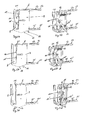
- FIG. 11 is a perspective view of a load securing system 1 for a truck with a superstructure according to an embodiment of the invention.
- the load securing system 1 comprises a Barrier 2, which extends transversely between two parallel spaced apart and spaced Einstecklatten 3, 3 ', and which serves for the positive securing of cargo.
- the locking bar 2 is formed as a rectangular profile.
- the Einstecklatten 3, 3 ' may consist of hoops of the structure of a tarpaulin vehicle, not shown here, and are at their respective ends 4, 4', 4 ". 4 '" fixed to stanchions of the structure, for example.
- the locking bar 2 has in the embodiment shown here at its two opposite end portions 5, 5 'in each case an end piece 6, 6' for receiving one of the Einstecklatten 3, 3 'on.
- the end pieces 6, 6 ' can be opened to insert and remove the Einstecklatten 3, 3' upwards.
- Fig. 2 is a front view of a barrier bar 2 of the in Fig. 1 illustrated load securing system 1 for trucks with body structure.
- Fig. 3 is a detail view of an end portion 5 of the in Fig. 2
- the end piece 6, which is arranged at the end portion 5 of the locking bar 2 has a housing 7 with a receptacle 8, wherein the Einstecklatte 3 is received and fixed in the receptacle 8 of the housing 7.
- the Einstecklatte 3 is formed as Doppelairlineschiene and further has two mutually parallel longitudinal grooves 9, 9 ', in which two extendable from the housing 7 pin, which in connection with FIG. 4 to be described in more detail, intervene.
- Fig. 4 is a detail view of an end portion 5 of the in Fig. 2 shown locking bar 2 without arranged in the receptacle 8 of the housing 7 of the tail 6 Einstecklatte.
- the end piece 6 or its housing 7 is shown in a fully closed state, which means that the two above-mentioned pins 10, 10 'are fully extended out of the housing 7 and protrude into the receptacle 8, a support bolt 11 is also fully extended out of the housing 7 and the Close receptacle 8 on the upper side.
- the retractable and extendable in the housing 7 bearing block 11 and also in the housing 7 retractable and extendable pins 10, 10 'are part of an opening and closing mechanism of the tail. 6
- FIGS. 5A and 5B are respective views of an end piece 6 of the in Fig. 2 illustrated locking bar, wherein the end piece 6 is in a closed or locking state.
- FIG. 5A is a view of the tail 6 with housing 7
- FIG. 5B is a view of the end piece 6 without the housing 7.
- arms 12, 12 'with respective slots 13, 13' are provided on the housing 7, which serve to receive the locking bar, not shown here.
- the end piece 6 has a provided in the receptacle 8 carriages 14, a locking pin 15 and a clamping lever 16.
- a spring tension system is arranged, which cooperates via compression springs 17, 17 'with the carriage 14 to actuate the opening and closing mechanism, which is two-stage.
- the locking pin 15 holds the carriage 14 in two defined positions.
- the carriage 14 Upon actuation of the locking bolt 15, for example by pulling, the carriage 14 by means of the spring pressure force jumps out of the housing 7 and closes the tail 6.
- FIGS. 6A and 6B are respective views of the in FIGS. 5A and 5B illustrated tail 6 in the half-open state.
- Fig. 6A a view of the end piece 6 with housing 7
- FIG. 6A is a view of the end piece 6 without the housing 7.
- the clamping lever 16 is brought by a first actuation in a first detent position, thereby causing the carriage 14 with the two pins 10, 10 'in the Housing 7 is completely retracted.
- the support bar 11 which serves to ensure that the locking bar, not shown here, remains lying on the Einstecklatte also not shown, half retracted into the housing 7.
- FIGS. 7A and 7B are respective views of the in FIGS. 5A and 5B illustrated tail 6 in the fully open state, again Fig. 7A a view of the end piece 6 with housing 7 and Fig. 7B a view of the end piece 6 without the housing 7 is.
- a second actuation of the clamping lever 16 in a second latching or end position of the support bolt 11 is now fully retracted into the housing 7, so that the receptacle 8 is opened up and a Einstecklatte can be inserted into the receptacle 8 or can be removed therefrom ,
- Fig. 8 shows that in Fig. 1 illustrated load securing system 1 with one-sided floating barrier bar 2.
- the Einstecklatte 3 can be removed from the receptacle 8.
- the locking bar 2 is then held only at its opposite end portion 5 'on the Einstecklatte 3' and is thus in a one-sided "floating" state. In In this condition, the cargo area is thus freely accessible and can be loaded and unloaded laterally.
Abstract
Description
Die Erfindung betrifft ein Ladungssicherungssystem für Lastfahrzeuge gemäß dem Oberbegriff des Anspruchs 1 und einen Sperrbalken für ein Ladungssicherungssystem gemäß dem Oberbegriff des Anspruchs 2.The invention relates to a load securing system for trucks according to the preamble of claim 1 and a locking bar for a load securing system according to the preamble of
Zum Transport von Gütern ist es im Straßenverkehr weit verbreitet, Planenfahrzeuge einzusetzen. Dabei sind die Fahrzeugaufbauten der Planenfahrzeuge sehr unterschiedlich konfiguriert. Es gibt beispielsweise Sattelauflieger mit Gardinenvorhang, sogenannte Curtainsider, Motorwagen mit Anhängern oder Bordwandfahrzeuge. Alle bekannten Fahrzeugaufbauten weisen feststehende oder verschiebbare Rungen auf, an denen reihenweise Spriegeltaschen angeordnet sind, welche nach oben und zur Seite hin offen sind, so dass die Spriegelbretter darin eingeführt und aufgenommen werden können. Auch hierbei ist die Ausführung dieser Spriegelbretter sehr unterschiedlich gestaltet. Sie können aus unterschiedlichen Materialien, wie beispielsweise Holz, Aluminium oder Stahl, gefertigt sein. Die Formgebung bei Holz ist rechteckig, bei Aluminium werden ein Hohlprofil mit einer oder mehreren Kammern oder auch sogenannte V-Latten eingesetzt, und bei Stahl werden üblicherweise gekantete Blechstreifen verwendet. Bekannt ist auch die Einbringung von Lochrasterungen zur Aufnahme weiterer Anschlusselemente.For the transport of goods, it is widely used in road traffic to use tarpaulin vehicles. The vehicle bodies of the tarpaulin vehicles are configured very differently. There are, for example, semi-trailers with curtain curtain, so-called curtainsider, motor vehicle with trailers or board wall vehicles. All known vehicle bodies have fixed or displaceable stanchions, on which rows of buckets are arranged, which are open at the top and to the side, so that the bowing boards can be inserted and received therein. Again, the design of this Spriegelbretter is designed very differently. They can be made of different materials, such as wood, aluminum or steel. The shape of wood is rectangular, in aluminum, a hollow section with one or more chambers or so-called V-slats are used, and in steel usually folded sheet metal strips are used. Also known is the introduction of perforated rasters for receiving further connection elements.
Zur eigentlichen Ladungssicherung kommen im Stand der Technik beispielsweise Zwischenwandverschlüsse und Sperrbalken zum Einsatz.For the actual load securing, for example, intermediate wall closures and barrier beams are used in the prior art.
Ein Zwischenwandverschluss wird hierzu formschlüssig zum Ladegut positioniert und sichert dieses somit gegen ein Verrutschen oder Kippen. Der Zwischenwandverschluss kann einfach und schnell gesetzt und gelöst werden. Über eine Klemmvorrichtung wird eine kraftschlüssige Verbindung mit dem Fahrzeug hergestellt. Diese Verbindung kann sowohl mit der Ladebordwand wie auch mit den Spriegelbrettern erfolgen. Die Klemmung erfolgt über ein Federspannsystem, welches mit Hilfe eines Hebels per Hand bedienbar ist. Der Klemmbereich der Stahlendstücke ist einstellbar und liegt üblicherweise zwischen 21 und 33 mm. Das Aluminiumprofil zwischen den Endstücken ist steck- und teleskopierbar. Der Einsatzbereich von Zwischenwandverschlüssen liegt in einem Bereich von 2400 mm bis 2700 mm und sie können eine Blockierkraft von 400 daN bereitstellen.An intermediate wall closure is for this purpose positively positioned for loading and thus secures this against slipping or tilting. The partition wall closure can be set and released easily and quickly. About a clamping device a positive connection with the vehicle is made. This connection can be made with both the tail lift and with the Spriegelbrettern. The clamping takes place via a spring tensioning system, which can be operated manually with the help of a lever. The clamping range of the steel end pieces is adjustable and is usually between 21 and 33 mm. The aluminum profile between the end pieces can be plugged in and telescoped. The area of use of intermediate wall closures is in a range of 2400 mm to 2700 mm and they can provide a blocking force of 400 daN.
Sperrbalken werden ebenfalls formschlüssig zum Ladegut positioniert. Die Sicherung der Ladung erfolgt, indem die Endzapfen formschlüssig in einer Lochrasterung verankert werden. Diese Lochrasterung kann sowohl im Dach-/Ladeflächenbereich als auch in den Seitenwänden oder Spriegelbrettern vorhanden sein. Der Sperrbalken ist üblicherweise auch teleskopierbar und verfügt über eine Spannvorrichtung, wobei ebenfalls Sicherungskräfte von 400 daN erzielt werden.Barrier bars are also positioned positively to the load. The securing of the load takes place by the end pins are anchored positively in a grid hole. This grid can be present in the roof / loading area as well as in the side walls or Spriegelbrettern. The locking bar is usually also telescopic and has a clamping device, with also securing forces of 400 daN can be achieved.
Um jedoch eine höhere Sicherungskraft zu erreichen, sind im Stand der Technik Ladungssicherungssysteme mit miteinander kombinierbaren Ladungssicherungshilfsmitteln und Zurrmitteln bekannt.However, in order to achieve a higher securing force, in the prior art, load securing systems with combinable load securing aids and lashing means are known.
Ein bekanntes Ladungssicherungssystem für Curtainsider weist zumindest zwei Einstecklatten, einen Sperrbalken und zwei Diagonal-Zurrgurte auf. Die Einstecklatte ist in der Länge anpassbar und verfügt über eine Rasterlochung, in der ein Standard-Spitzhaken arretiert oder der Sperrbalken mit seinem Hakenende eingerastet werden kann. Dadurch entstehen eine Vielfalt im Anwendungsbereich und eine gute Kompatibilität des Systems mit anderen Elementen. Der Sperrbalken wird in zwei Ausführungen bereitgestellt. Abhängig vom Laderaum und von der Belastung kann zwischen einem breiten und einem schmalen Sperrbalken ausgewählt werden. Beide besitzen an den jeweiligen Enden Haken, mit denen sie fest an den Spriegelbrettern arretierbar sind. Die wirkenden Kräfte können somit über die Spriegelbretter an den Aufbau des Transportmittels übertragen werden. An der Unterseite der breiten Ausführung befinden sich zwei Einhakösen. Diese erlauben eine sichere Verbindung mit den Zurrgurten und ermöglichen so auch die Diagonalabspannung. Die schmale Ausführung besteht aus dem Einstecklattenprofil und kann die Verbindung mit den Zurrgurten über die Rasterlochung eingehen. Mittels dieses Ladungssicherungssystems ist es möglich, Ladungen in allen Richtungen zu blockieren, jedoch ist eine seitliche Be- und Entladung mit nur einseitigem Aufplanen nicht möglich.A known load securing system for curtainsiders has at least two Einstecklatten, a locking bar and two diagonal lashing straps. The Einstecklatte is adaptable in length and has a grid holes, in which a standard hook can be locked or the locking bar can be snapped with its hook end. This creates a variety in the scope and a good Compatibility of the system with other elements. The locking bar is provided in two versions. Depending on the loading space and the load, you can choose between a wide and a narrow barrier bar. Both have at the respective ends hooks, with which they are firmly locked to the Spriegelbrettern. The acting forces can thus be transmitted via the Spriegelbretter to the structure of the means of transport. At the bottom of the wide version there are two hook eyes. These allow a secure connection with the lashing straps and thus also allow the diagonal bracing. The narrow version consists of the Einstecklattenprofil and can enter the connection with the lashing straps on the grid perforations. By means of this load securing system, it is possible to block charges in all directions, but a lateral loading and unloading with only one-sided planing is not possible.
Ein weiteres aus dem Stand der Technik bekanntes Ladungssicherungssystem besteht aus Einstecklatten und Sperrlatten und kann zudem mit runden Sperrstangen, Vierkantsperrbalken, Zurrgurten und Kleidertransportstangen erweitert werden. Die Einstecklatten verfügen über eine Kombistanzung, welche die Verbindung mit unterschiedlichen Ladungssicherungshilfsmitteln wie Rundstangen, Vierkantsperrbalken, etc. ermöglicht. Die Sperrlatten verfügen an den Enden über zwei universale Endstücke mit Teleskopfunktion, welche in den Schlitz der Einstecklatte formschlüssig einrasten. Die Ladung kann dadurch formschlüssig gesichert und in die wirkenden Kräfte in den Aufbau des Transportmittels eingeleitet werden. Auch dieses System ist in der Lage, Ladungen in allen Richtungen zu blockieren, ermöglicht aber, wie auch die zuvor beschriebenen Lösungen, keine seitliche Be- und Entladung mit nur einseitigem Aufplanen, wodurch ein hoher zeitlicher und damit verbundener finanzieller Aufwand entsteht.Another known from the prior art load securing system consists of Einstecklatten and barrier slats and can also be expanded with round locking bars, square locking bars, lashing straps and garment transport rods. The Einstecklatten have a combination punching, which allows the connection with different load securing aids such as round bars, square locking bars, etc. The barrier slats have at the ends of two universal end pieces with telescopic function, which engage positively in the slot of the Einstecklatte. The charge can thereby be positively secured and introduced into the forces acting in the structure of the means of transport. Also, this system is able to block charges in all directions, but allows, as well as the solutions described above, no lateral loading and unloading with only one-sided planning, resulting in a high temporal and associated financial costs.
Vor diesem Hintergrund liegt der Erfindung die Aufgabe zugrunde, eine Lösung zur Ladungssicherung auf Planenfahrzeugen bereitzustellen, welche hohe Sicherungskräfte gewährleistet und gleichzeitig ein seitliches Be- und Entladen mit nur einseitigem Aufplanen ermöglicht.Against this background, the invention has for its object to provide a solution for securing cargo on tarpaulin vehicles, which ensures high security forces while allowing lateral loading and unloading with only one-sided planing.
Diese Aufgabe wird gemäß der Erfindung wird durch ein Ladungssicherungssystem mit den in Anspruch 1 angegebenen Merkmalen sowie durch einen Sperrbalken mit den in Anspruch 2 angegebenen Merkmalen gelöst. Vorteilhafte Ausgestaltungen der Erfindung sind in den Unteransprüchen, der nachfolgenden Beschreibung und der Zeichnung angegeben.This object is achieved according to the invention by a load securing system having the features specified in claim 1 and by a locking bar having the features specified in
Erfindungsgemäß wird ein Ladungssicherungssystem für Lastfahrzeuge mit Aufbaustruktur, welche Rungen umfasst, bereitgestellt, wobei das Ladungssicherungssystem zumindest zwei in Längsrichtung des Lastfahrzeugs verlaufende und voneinander beabstandete Einstecklatten, welche in jeweiligen Rungen der Aufbaustruktur fixierbar sind, und zumindest einen zwischen den Einstecklatten quer angeordneten Sperrbalken zur formschlüssigen Sicherung von Ladung umfasst, wobei der zumindest eine Sperrbalken zumindest an einem Endabschnitt mit einem Endstück zur Aufnahme einer der zumindest zwei Einstecklatten versehen ist, wobei das Endstück zum Einlegen und zum Entnehmen der Einstecklatte nach oben und/oder nach unten geöffnet werden kann. Durch das erfindungsgemäße Ladungssicherungssystem kann ein Lastfahrzeug, wie beispielsweise ein Curtainsider, be- und entladen werden, ohne dabei den gesamten Curtainsider aufzuplanen. Weiterhin kann eine positionsunabhängige Be- und Entladung des Lastfahrzeugs bei aufeinander folgenden Ladeeinheiten erfolgen. Aufgrund des nach oben zu öffnenden Endstücks kann eine Einstecklatte aus dem quer angeordneten Sperrbalken entnommen werden, woraufhin der Sperrbalken in einem einseitig "schwebenden" Zustand ist, so dass eine seitliche Zugänglichkeit der Ladung gewährleistet ist. Diese kann somit entnommen werden und der entstandene Freiraum neu beladen werden. Hierdurch können bei der Be- und Entladung Zeit und somit auch Kosten eingespart werden, was den Be- und Entladevorgang deutlich effizienter macht.According to the invention, a load securing system for load vehicles with a body structure comprising stanchions is provided, wherein the load securing system at least two Einstecklatten extending in the longitudinal direction of the truck and spaced apart, which are fixable in respective stanchions of the body structure, and at least one interposed between the Einstecklatten locking bar for positive locking Securing cargo comprises, wherein the at least one locking bar is provided at least at one end portion with an end piece for receiving one of the at least two Einstecklatten, wherein the end piece for inserting and for removing the Einstecklatte can be opened upwards and / or downwards. By the load securing system according to the invention, a load vehicle, such as a curtainsider loaded and unloaded, without aufzuschplene the entire curtainsider. Furthermore, a position-independent loading and unloading of the load vehicle can take place in successive loading units. Due to the upwardly open end piece, a Einstecklatte be removed from the transversely arranged locking bar, whereupon the locking bar is in a one-sided "floating" state, so that a lateral accessibility of the charge is ensured. This can thus be removed and the space created will be reloaded. As a result, time and thus costs can be saved during loading and unloading, which makes the loading and unloading much more efficient.
Weiterhin wird gemäß der Erfindung ein Sperrbalken, insbesondere für ein Ladungssicherungssystem für Lastfahrzeuge mit Aufbaustruktur, bereitgestellt, wobei der Sperrbalken zumindest an einem Endabschnitt mit einem Endstück versehen ist, in welchem eine Einstecklatte des Ladungssicherungssystems aufnehmbar ist, wobei das Endstück zum Einlegen und zum Entnehmen der Einstecklatte nach oben und/oder nach unten geöffnet werden kann. Durch die Möglichkeit, das Endstück nach oben oder nach unten zu öffnen, so dass der Sperrbalken in einem einseitig "schwebenden" Zustand gehalten wird, werden die gleichen Vorteile, wie oben bereits beschrieben, erzielt. Weiterhin, da die Verbindung der Endstücke mit dem Sperrbalken in einem Drehwinkel von 180° erfolgen kann, kann die Öffnung der Endstücke entweder nach oben, nach unten oder nach oben und unten zeigen. Dadurch ist eine Vielfalt der Anwendung und Handhabung gegeben.Furthermore, according to the invention, a locking bar, in particular for a load securing system for load vehicles with body structure, provided, wherein the locking bar is provided at least at one end portion with an end piece in which a Einstecklatte the load securing system is receivable, wherein the end piece for inserting and removing the Einstecklatte can be opened upwards and / or downwards. The ability to open the tail upwardly or downwardly so as to maintain the barrier beam in a one-way "floating" condition provides the same advantages as previously described. Furthermore, since the connection of the end pieces can be made with the locking bar in a rotation angle of 180 °, the opening of the end pieces can show either up, down or up and down. This provides a variety of application and handling.
Gemäß einer bevorzugten Ausführungsform weist das Endstück einen zweistufigen Öffnungs- und Schließmechanismus auf.According to a preferred embodiment, the tail has a two-stage opening and closing mechanism.
Gemäß einer weiteren bevorzugten Ausführungsform weist der Öffnungs- und Schließmechanismus ein Gehäuse mit Befestigungseinrichtungen, insbesondere mit Langlöchern, zur Befestigung des Gehäuses an dem Sperrbalken auf.According to a further preferred embodiment, the opening and closing mechanism has a housing with fastening devices, in particular with oblong holes, for fastening the housing to the blocking beam.
Vorzugsweise ist das Gehäuse mit einer Aufnahme versehen, in welcher die Einstecklatte aufnehmbar ist.Preferably, the housing is provided with a receptacle in which the Einstecklatte is receivable.
Weiterhin weist gemäß einer bevorzugten Ausführungsform der Öffnungs- und Schließmechanismus zwei Zapfen auf, welche in das Gehäuse ein- und ausfahrbar sind. In ausgefahrenem Zustand liegen die zwei Zapfen an einer in die Aufnahme eingelegten Einstecklatte, insbesondere in zwei entsprechenden Rillen der Einstecklatte, an, um diese in der Aufnahme zu sichern. In eingefahrenem Zustand, in welchem die zwei Zapfen in das Gehäuse eingefahren sind, wird die Einstecklatte wieder freigegeben.Furthermore, according to a preferred embodiment, the opening and closing mechanism on two pins, which are in and out of the housing. In the extended state, the two pins are located on an inserted in the receptacle Einstecklatte, in particular in two corresponding grooves of the Einstecklatte, to secure them in the recording. In the retracted state, in which the two pins are retracted into the housing, the Einstecklatte is released again.
Darüber hinaus ist es vorteilhaft, wenn der Öffnungs- und Schließmechanismus einen in das Gehäuse ein- und ausfahrbaren Auflageriegel umfasst, welcher die Aufnahme zumindest teilweise verschließt und freigibt. Der Auflageriegel sorgt dafür, dass der Sperrbalken auf der Einstecklatte liegen bleibt und ohne große Mühe verschoben werden kann. Der Auflageriegel hält die in der Aufnahme aufgenommene Einstecklatte in der Aufnahme bzw. gibt diese frei, so dass die Einstecklatte entnehmbar ist und ein seitliches Be- oder Entladen mit nur einseitigem Aufplanen erfolgen kann.Moreover, it is advantageous if the opening and closing mechanism comprises a support bar which can be moved in and out of the housing and at least partially closes and releases the receptacle. The support bar ensures that the locking bar remains on the Einstecklatte and can be moved without much effort. The Auflageriegel holds the recorded in the receptacle Einstecklatte in the recording or releases them, so that the Einstecklatte can be removed and a lateral loading or unloading can be done with only one-sided planing.
Von Vorteil ist auch, wenn der Öffnungs- und Schließmechanismus einen Spannhebel umfasst, welcher in Folge einer ersten Betätigung bewirkt, dass die zwei Zapfen in das Gehäuse eingefahren werden.It is also advantageous if the opening and closing mechanism comprises a clamping lever which, as a result of a first actuation, causes the two pins to be retracted into the housing.
Vorzugsweise bewirkt der Spannhebel in Folge einer zweiten Betätigung, dass der Auflageriegel in das Gehäuse eingefahren wird.As a result of a second actuation, the tension lever preferably causes the bearing bolt to be retracted into the housing.
Gemäß noch einer weiteren bevorzugten Ausführungsform ist in dem Gehäuse ein Federspannsystem angeordnet, welches über Druckfedern mit einem Schlitten zusammenwirkt, um den zweistufigen Öffnungs- und Schließmechanismus zu betätigen.According to yet another preferred embodiment, a spring tension system is arranged in the housing, which cooperates via compression springs with a carriage to actuate the two-stage opening and closing mechanism.
Der Sperrbalken kann weiterhin als Rechteckprofil ausgebildet sein.The locking bar can continue to be formed as a rectangular profile.
Die Erfindung ist nachfolgend anhand eines in der Zeichnung dargestellten Ausführungsbeispiels näher erläutert. Es zeigen
- Fig. 1
- eine perspektivische Darstellung eines Ladungssicherungssystems gemäß einer Ausführungsform der Erfindung;
- Fig. 2
- eine Vorderansicht eines Sperrbalkens des in
Fig. 1 dargestellten Ladungssicherungssystems; - Fig. 3
- eine Detailansicht eines Endabschnitts des in
Fig. 2 dargestellten Sperrbalkens mit damit verbundener Einstecklatte; - Fig. 4
- eine Detailansicht eines Endabschnitts des in
Fig. 2 dargestellten Sperrbalkens ohne Einstecklatte; - Fig. 5A, 5B
- jeweilige Ansichten eines Endstücks des in
Fig. 2 dargestellten Sperrbalkens, wobei das Endstück in geschlossenem Zustand ist; - Fig. 6A, 6B
- jeweilige Ansichten des in
Fig. 5A und Fig. 5B dargestellten Endstücks in halb geöffnetem Zustand; - Fig. 7A, 7B
- jeweilige Ansichten des in
Fig. 5A und Fig. 5B dargestellten Endstücks in vollständig geöffnetem Zustand; und - Fig. 8
- das in
Fig. 1 dargestellte Ladungssicherungssystem mit einseitig schwebendem Sperrbalken.
- Fig. 1
- a perspective view of a load securing system according to an embodiment of the invention;
- Fig. 2
- a front view of a barrier bar of the in
Fig. 1 illustrated load securing system; - Fig. 3
- a detailed view of an end portion of in
Fig. 2 illustrated barrier bar with associated Einstecklatte; - Fig. 4
- a detailed view of an end portion of in
Fig. 2 illustrated barrier bar without Einstecklatte; - Fig. 5A, 5B
- respective views of an end of the in
Fig. 2 illustrated locking bar, wherein the tail is in the closed state; - Fig. 6A, 6B
- respective views of the in
FIGS. 5A and 5B illustrated tail in half-open condition; - Fig. 7A, 7B
- respective views of the in
FIGS. 5A and 5B illustrated tail in fully open condition; and - Fig. 8
- this in
Fig. 1 illustrated load securing system with one-sided floating barrier bar.
- 11
- - Ladungssicherungssystem- Load securing system
- 22
- - Sperrbalken- Barrier
- 3, 3'3, 3 '
- - Einstecklatten- Slats
- 4, 4', 4", 4'"4, 4 ', 4 ", 4'"
- - Enden der Einstecklatten- ends of the slats
- 5, 5'5, 5 '
- - Endabschnitte des Sperrbalkens- End sections of the barrier bar
- 6, 6'6, 6 '
- - Endstücke- Tails
- 77
- - Gehäuse- Casing
- 88th
- - Aufnahme- Admission
- 9, 9'9, 9 '
- - Längsrillen- longitudinal grooves
- 10, 10'10, 10 '
- - Zapfen- cones
- 1111
- - Auflageriegel- bearing bolt
- 12, 12'12, 12 '
- - Arme- Poor
- 13, 13'13, 13 '
- - Langlöcher- long holes
- 1414
- - Schlitten- sledges
- 1515
- - Arretierbolzen- locking bolt
- 1616
- - Spannhebel- Tensioning lever
- 17, 17'17, 17 '
- - Druckfedern- compression springs
Claims (11)
dadurch gekennzeichnet, dass
der zumindest eine Sperrbalken (2) zumindest an einem Endabschnitt (5, 5') mit einem Endstück (6, 6') zur Aufnahme einer der zumindest zwei Einstecklatten (3, 3') versehen ist, wobei das Endstück (6, 6') zum Einlegen und zum Entnehmen der Einstecklatte (3, 3') nach oben und/oder nach unten geöffnet werden kann.Load securing system (1) for trucks with body structure, which includes stanchions, wherein the load securing system (1) at least two extending in the longitudinal direction of the truck and spaced Einstecklatten (3, 3 '), which are fixable in respective stanchions of the body structure, and at least one between the Einstecklatten (3, 3 ') comprises transversely arranged locking bar (2) for the positive securing of cargo,
characterized in that
the at least one blocking bar (2) is provided at least at one end section (5, 5 ') with an end piece (6, 6') for receiving one of the at least two insert slats (3, 3 '), the end section (6, 6' ) for inserting and removing the Einstecklatte (3, 3 ') can be opened upwards and / or downwards.
dadurch gekennzeichnet, dass
der Sperrbalken (2) zumindest an einem Endabschnitt (5, 5') mit einem Endstück (6, 6') versehen ist, in welchem eine Einstecklatte (3, 3') des Ladungssicherungssystems (1) aufnehmbar ist, wobei das Endstück (6, 6') zum Einlegen und zum Entnehmen der Einstecklatte (3, 3') nach oben und/oder nach unten geöffnet werden kann.Barrier bar (2), in particular for a load securing system (1) for heavy goods vehicles with body structure,
characterized in that
the locking bar (2) is provided with an end piece (6, 6 ') at least at one end section (5, 5') in which an insert bar (3, 3 ') of the load securing system (1) can be received, the end piece (6 , 6 ') for insertion and removal of the Einstecklatte (3, 3') can be opened upwards and / or downwards.
Applications Claiming Priority (1)
| Application Number | Priority Date | Filing Date | Title |
|---|---|---|---|
| DE201320001547 DE202013001547U1 (en) | 2013-02-19 | 2013-02-19 | Flexible plug-in charging system |
Publications (1)
| Publication Number | Publication Date |
|---|---|
| EP2767437A1 true EP2767437A1 (en) | 2014-08-20 |
Family
ID=48084828
Family Applications (1)
| Application Number | Title | Priority Date | Filing Date |
|---|---|---|---|
| EP14155203.4A Withdrawn EP2767437A1 (en) | 2013-02-19 | 2014-02-14 | Flexible insertion storage system |
Country Status (2)
| Country | Link |
|---|---|
| EP (1) | EP2767437A1 (en) |
| DE (2) | DE202013001547U1 (en) |
Citations (4)
| Publication number | Priority date | Publication date | Assignee | Title |
|---|---|---|---|---|
| US3952671A (en) * | 1975-02-02 | 1976-04-27 | Transco Inc. | Universal crossbar head for engaging beltrails |
| DE20012731U1 (en) * | 1999-12-13 | 2000-12-14 | Ancra Jungfalk Gmbh & Co Kg | Device for securing cargo on the loading surface of a vehicle |
| DE20219098U1 (en) * | 2002-12-09 | 2003-03-13 | Ancra Jungfalk Gmbh & Co Kg | Clamping device for securing of loaded goods, comprising sliding profile made of sheet metal |
| DE202008012788U1 (en) * | 2008-09-25 | 2008-11-27 | Allsafe Jungfalk Gmbh & Co. Kg | Load bar |
-
2013
- 2013-02-19 DE DE201320001547 patent/DE202013001547U1/en not_active Expired - Lifetime
-
2014
- 2014-02-14 DE DE201420105561 patent/DE202014105561U1/en not_active Expired - Lifetime
- 2014-02-14 EP EP14155203.4A patent/EP2767437A1/en not_active Withdrawn
Patent Citations (4)
| Publication number | Priority date | Publication date | Assignee | Title |
|---|---|---|---|---|
| US3952671A (en) * | 1975-02-02 | 1976-04-27 | Transco Inc. | Universal crossbar head for engaging beltrails |
| DE20012731U1 (en) * | 1999-12-13 | 2000-12-14 | Ancra Jungfalk Gmbh & Co Kg | Device for securing cargo on the loading surface of a vehicle |
| DE20219098U1 (en) * | 2002-12-09 | 2003-03-13 | Ancra Jungfalk Gmbh & Co Kg | Clamping device for securing of loaded goods, comprising sliding profile made of sheet metal |
| DE202008012788U1 (en) * | 2008-09-25 | 2008-11-27 | Allsafe Jungfalk Gmbh & Co. Kg | Load bar |
Also Published As
| Publication number | Publication date |
|---|---|
| DE202013001547U1 (en) | 2013-03-12 |
| DE202014105561U1 (en) | 2014-12-15 |
Similar Documents
| Publication | Publication Date | Title |
|---|---|---|
| DE102013222651B4 (en) | Device for securing cargo in a loading space and fastening element therefor | |
| EP1140666A1 (en) | Device for storing and transporting flat objects | |
| DE102008048151A1 (en) | Device for dividing cargo compartment, particularly of van, has door-like structure, which is laterally moved away in its appropriate level | |
| DE102021103413A1 (en) | Camping vehicle | |
| DE69725164T2 (en) | LASTENING SYSTEM AND METHOD FOR HOLDING LOADS | |
| DE202009007027U1 (en) | Device for securing goods on a vehicle | |
| EP2949492A1 (en) | Sliding canvas cover for with secure cover tensioning profile | |
| DE102014110932B3 (en) | Retrofit kit for a freight container, freight container with retrofit kit and process for retrofitting a freight container | |
| DE102018122634A1 (en) | Load securing system and vehicle comprising such a system and a method for securing loads | |
| EP2767437A1 (en) | Flexible insertion storage system | |
| EP2955086B1 (en) | Commercial vehicle structure with pivoting side wall element | |
| EP2708393B1 (en) | Vehicle structure for the transport of bulk or stackable transport goods | |
| DE10155728B4 (en) | Vehicle with loading floor | |
| EP3247589A1 (en) | Transport vehicle | |
| DE202008012869U1 (en) | Device for the vertical determination of cargo on loading areas of containers | |
| DE102015112843A1 (en) | Runge for a commercial vehicle body and load securing system, commercial vehicle body and commercial vehicle with such a stanchion | |
| DE102016115786B4 (en) | Load securing device for commercial vehicles | |
| EP2910418A1 (en) | Load securing device for a commercial vehicle | |
| EP3587181B1 (en) | Transport vehicle | |
| DE202016106739U1 (en) | Transport vehicle, in particular truck semi-trailer | |
| DE102017206905A1 (en) | Luggage compartment cover and separating device | |
| DE202009005108U1 (en) | Convertible top for a transport vehicle | |
| EP3581469B1 (en) | Commercial vehicle chassis with a pickup for temporary stowage of elongated equipment components | |
| DE102006025118B4 (en) | vehicle | |
| DE102015102147A1 (en) | Interior roof rack |
Legal Events
| Date | Code | Title | Description |
|---|---|---|---|
| PUAI | Public reference made under article 153(3) epc to a published international application that has entered the european phase |
Free format text: ORIGINAL CODE: 0009012 |
|
| 17P | Request for examination filed |
Effective date: 20140214 |
|
| AK | Designated contracting states |
Kind code of ref document: A1 Designated state(s): AL AT BE BG CH CY CZ DE DK EE ES FI FR GB GR HR HU IE IS IT LI LT LU LV MC MK MT NL NO PL PT RO RS SE SI SK SM TR |
|
| AX | Request for extension of the european patent |
Extension state: BA ME |
|
| STAA | Information on the status of an ep patent application or granted ep patent |
Free format text: STATUS: THE APPLICATION IS DEEMED TO BE WITHDRAWN |
|
| 18D | Application deemed to be withdrawn |
Effective date: 20150221 |