EP2767376B2 - Method and high-pressure mixing apparatus with self-regenerating seal - Google Patents
Method and high-pressure mixing apparatus with self-regenerating seal Download PDFInfo
- Publication number
- EP2767376B2 EP2767376B2 EP14155160.6A EP14155160A EP2767376B2 EP 2767376 B2 EP2767376 B2 EP 2767376B2 EP 14155160 A EP14155160 A EP 14155160A EP 2767376 B2 EP2767376 B2 EP 2767376B2
- Authority
- EP
- European Patent Office
- Prior art keywords
- mixing chamber
- sealing element
- annular sealing
- bush
- seat
- Prior art date
- Legal status (The legal status is an assumption and is not a legal conclusion. Google has not performed a legal analysis and makes no representation as to the accuracy of the status listed.)
- Active
Links
- 238000002156 mixing Methods 0.000 title claims description 147
- 238000000034 method Methods 0.000 title claims description 15
- 238000007789 sealing Methods 0.000 claims description 74
- 239000000203 mixture Substances 0.000 claims description 41
- 238000004140 cleaning Methods 0.000 claims description 26
- 238000002347 injection Methods 0.000 claims description 15
- 239000007924 injection Substances 0.000 claims description 15
- 229920005989 resin Polymers 0.000 claims description 15
- 239000011347 resin Substances 0.000 claims description 15
- 229920003002 synthetic resin Polymers 0.000 claims description 4
- 239000000057 synthetic resin Substances 0.000 claims description 3
- 238000004891 communication Methods 0.000 claims description 2
- 239000000945 filler Substances 0.000 claims description 2
- 238000005187 foaming Methods 0.000 claims description 2
- 230000001172 regenerating effect Effects 0.000 claims description 2
- 238000003892 spreading Methods 0.000 claims description 2
- 239000000126 substance Substances 0.000 description 16
- 239000000243 solution Substances 0.000 description 9
- 125000006850 spacer group Chemical group 0.000 description 5
- 238000012423 maintenance Methods 0.000 description 4
- 238000004519 manufacturing process Methods 0.000 description 3
- 239000000463 material Substances 0.000 description 3
- 238000004873 anchoring Methods 0.000 description 2
- 230000015572 biosynthetic process Effects 0.000 description 2
- 230000001010 compromised effect Effects 0.000 description 2
- 230000009977 dual effect Effects 0.000 description 2
- 239000006260 foam Substances 0.000 description 2
- 239000002245 particle Substances 0.000 description 2
- 229920002635 polyurethane Polymers 0.000 description 2
- 239000004814 polyurethane Substances 0.000 description 2
- 238000003860 storage Methods 0.000 description 2
- 238000012360 testing method Methods 0.000 description 2
- 208000034693 Laceration Diseases 0.000 description 1
- 229920005830 Polyurethane Foam Polymers 0.000 description 1
- 238000009825 accumulation Methods 0.000 description 1
- 239000011324 bead Substances 0.000 description 1
- 239000011248 coating agent Substances 0.000 description 1
- 238000000576 coating method Methods 0.000 description 1
- 230000000052 comparative effect Effects 0.000 description 1
- 230000007423 decrease Effects 0.000 description 1
- 239000012948 isocyanate Substances 0.000 description 1
- 150000002513 isocyanates Chemical class 0.000 description 1
- 230000013011 mating Effects 0.000 description 1
- 238000013021 overheating Methods 0.000 description 1
- 230000000149 penetrating effect Effects 0.000 description 1
- 229920000642 polymer Polymers 0.000 description 1
- 239000002952 polymeric resin Substances 0.000 description 1
- 239000011496 polyurethane foam Substances 0.000 description 1
- 230000003134 recirculating effect Effects 0.000 description 1
- 230000008929 regeneration Effects 0.000 description 1
- 238000011069 regeneration method Methods 0.000 description 1
- 230000000717 retained effect Effects 0.000 description 1
- 230000008961 swelling Effects 0.000 description 1
Images


Classifications
-
- B—PERFORMING OPERATIONS; TRANSPORTING
- B29—WORKING OF PLASTICS; WORKING OF SUBSTANCES IN A PLASTIC STATE IN GENERAL
- B29B—PREPARATION OR PRETREATMENT OF THE MATERIAL TO BE SHAPED; MAKING GRANULES OR PREFORMS; RECOVERY OF PLASTICS OR OTHER CONSTITUENTS OF WASTE MATERIAL CONTAINING PLASTICS
- B29B7/00—Mixing; Kneading
- B29B7/74—Mixing; Kneading using other mixers or combinations of mixers, e.g. of dissimilar mixers ; Plant
- B29B7/76—Mixers with stream-impingement mixing head
- B29B7/7663—Mixers with stream-impingement mixing head the mixing head having an outlet tube with a reciprocating plunger, e.g. with the jets impinging in the tube
- B29B7/7684—Parts; Accessories
- B29B7/7689—Plunger constructions
- B29B7/7694—Plunger constructions comprising recirculation channels; ducts formed in the plunger
-
- B—PERFORMING OPERATIONS; TRANSPORTING
- B01—PHYSICAL OR CHEMICAL PROCESSES OR APPARATUS IN GENERAL
- B01J—CHEMICAL OR PHYSICAL PROCESSES, e.g. CATALYSIS OR COLLOID CHEMISTRY; THEIR RELEVANT APPARATUS
- B01J19/00—Chemical, physical or physico-chemical processes in general; Their relevant apparatus
- B01J19/0053—Details of the reactor
- B01J19/0073—Sealings
-
- B—PERFORMING OPERATIONS; TRANSPORTING
- B29—WORKING OF PLASTICS; WORKING OF SUBSTANCES IN A PLASTIC STATE IN GENERAL
- B29B—PREPARATION OR PRETREATMENT OF THE MATERIAL TO BE SHAPED; MAKING GRANULES OR PREFORMS; RECOVERY OF PLASTICS OR OTHER CONSTITUENTS OF WASTE MATERIAL CONTAINING PLASTICS
- B29B7/00—Mixing; Kneading
- B29B7/74—Mixing; Kneading using other mixers or combinations of mixers, e.g. of dissimilar mixers ; Plant
- B29B7/7404—Mixing devices specially adapted for foamable substances
-
- B—PERFORMING OPERATIONS; TRANSPORTING
- B29—WORKING OF PLASTICS; WORKING OF SUBSTANCES IN A PLASTIC STATE IN GENERAL
- B29B—PREPARATION OR PRETREATMENT OF THE MATERIAL TO BE SHAPED; MAKING GRANULES OR PREFORMS; RECOVERY OF PLASTICS OR OTHER CONSTITUENTS OF WASTE MATERIAL CONTAINING PLASTICS
- B29B7/00—Mixing; Kneading
- B29B7/74—Mixing; Kneading using other mixers or combinations of mixers, e.g. of dissimilar mixers ; Plant
- B29B7/76—Mixers with stream-impingement mixing head
- B29B7/7663—Mixers with stream-impingement mixing head the mixing head having an outlet tube with a reciprocating plunger, e.g. with the jets impinging in the tube
- B29B7/7668—Mixers with stream-impingement mixing head the mixing head having an outlet tube with a reciprocating plunger, e.g. with the jets impinging in the tube having a second tube intersecting the first one with the jets impinging in the second tube
-
- B—PERFORMING OPERATIONS; TRANSPORTING
- B29—WORKING OF PLASTICS; WORKING OF SUBSTANCES IN A PLASTIC STATE IN GENERAL
- B29B—PREPARATION OR PRETREATMENT OF THE MATERIAL TO BE SHAPED; MAKING GRANULES OR PREFORMS; RECOVERY OF PLASTICS OR OTHER CONSTITUENTS OF WASTE MATERIAL CONTAINING PLASTICS
- B29B7/00—Mixing; Kneading
- B29B7/74—Mixing; Kneading using other mixers or combinations of mixers, e.g. of dissimilar mixers ; Plant
- B29B7/76—Mixers with stream-impingement mixing head
- B29B7/7663—Mixers with stream-impingement mixing head the mixing head having an outlet tube with a reciprocating plunger, e.g. with the jets impinging in the tube
- B29B7/7684—Parts; Accessories
-
- B—PERFORMING OPERATIONS; TRANSPORTING
- B29—WORKING OF PLASTICS; WORKING OF SUBSTANCES IN A PLASTIC STATE IN GENERAL
- B29B—PREPARATION OR PRETREATMENT OF THE MATERIAL TO BE SHAPED; MAKING GRANULES OR PREFORMS; RECOVERY OF PLASTICS OR OTHER CONSTITUENTS OF WASTE MATERIAL CONTAINING PLASTICS
- B29B7/00—Mixing; Kneading
- B29B7/80—Component parts, details or accessories; Auxiliary operations
- B29B7/802—Constructions or methods for cleaning the mixing or kneading device
- B29B7/803—Cleaning of mixers of the gun type, stream-impigement type, mixing heads
- B29B7/805—Cleaning of the mixing conduit, module or chamber part
-
- B—PERFORMING OPERATIONS; TRANSPORTING
- B29—WORKING OF PLASTICS; WORKING OF SUBSTANCES IN A PLASTIC STATE IN GENERAL
- B29C—SHAPING OR JOINING OF PLASTICS; SHAPING OF MATERIAL IN A PLASTIC STATE, NOT OTHERWISE PROVIDED FOR; AFTER-TREATMENT OF THE SHAPED PRODUCTS, e.g. REPAIRING
- B29C44/00—Shaping by internal pressure generated in the material, e.g. swelling or foaming ; Producing porous or cellular expanded plastics articles
- B29C44/02—Shaping by internal pressure generated in the material, e.g. swelling or foaming ; Producing porous or cellular expanded plastics articles for articles of definite length, i.e. discrete articles
- B29C44/12—Incorporating or moulding on preformed parts, e.g. inserts or reinforcements
- B29C44/1271—Incorporating or moulding on preformed parts, e.g. inserts or reinforcements the preformed parts being partially covered
-
- B—PERFORMING OPERATIONS; TRANSPORTING
- B29—WORKING OF PLASTICS; WORKING OF SUBSTANCES IN A PLASTIC STATE IN GENERAL
- B29C—SHAPING OR JOINING OF PLASTICS; SHAPING OF MATERIAL IN A PLASTIC STATE, NOT OTHERWISE PROVIDED FOR; AFTER-TREATMENT OF THE SHAPED PRODUCTS, e.g. REPAIRING
- B29C67/00—Shaping techniques not covered by groups B29C39/00 - B29C65/00, B29C70/00 or B29C73/00
- B29C67/24—Shaping techniques not covered by groups B29C39/00 - B29C65/00, B29C70/00 or B29C73/00 characterised by the choice of material
- B29C67/246—Moulding high reactive monomers or prepolymers, e.g. by reaction injection moulding [RIM], liquid injection moulding [LIM]
-
- B—PERFORMING OPERATIONS; TRANSPORTING
- B01—PHYSICAL OR CHEMICAL PROCESSES OR APPARATUS IN GENERAL
- B01J—CHEMICAL OR PHYSICAL PROCESSES, e.g. CATALYSIS OR COLLOID CHEMISTRY; THEIR RELEVANT APPARATUS
- B01J2219/00—Chemical, physical or physico-chemical processes in general; Their relevant apparatus
- B01J2219/00761—Details of the reactor
-
- B—PERFORMING OPERATIONS; TRANSPORTING
- B29—WORKING OF PLASTICS; WORKING OF SUBSTANCES IN A PLASTIC STATE IN GENERAL
- B29K—INDEXING SCHEME ASSOCIATED WITH SUBCLASSES B29B, B29C OR B29D, RELATING TO MOULDING MATERIALS OR TO MATERIALS FOR MOULDS, REINFORCEMENTS, FILLERS OR PREFORMED PARTS, e.g. INSERTS
- B29K2075/00—Use of PU, i.e. polyureas or polyurethanes or derivatives thereof, as moulding material
Definitions
- the present invention refers to a high-pressure mixing apparatus for polymeric components for a reactive chemical mixture of a polymerisable resin, and more properly refers to a method for providing a self-regenerating seal in the mixing chamber of the mixing apparatus, in which a recirculation valving member for the polymeric components slides.
- a self-cleaning high-pressure mixing apparatus usually comprises at least one mixing chamber in which two or more polymeric components are impinging with great kinetic energy to form a reactive mixture, and in which the resulting reactive mixture outcoming the mixing chamber flows into a delivering conduit to be injected or fed into a mould.
- the mixing apparatus further comprises a sliding valve member or spool slidable in the mixing chamber, which is provided with longitudinal grooves for the recirculation of the single chemical components in the closed condition of the apparatus; the sliding valve member is axially movable between a retracted position, in which both injection holes for the chemical components and the mixing chamber open to the delivering conduit, and an advanced position for recirculation of the single polymeric components, in which closes the mixing chamber, expelling the residual mixture directly into the delivering conduit.
- the residual mixture is in turn ejected from the delivering conduit by a cleaning member, consisting of a cylindrical pin that closes the front side of the valve member and of the mixing chamber, preventing the chemical components from leaking outwards.
- a cleaning member consisting of a cylindrical pin that closes the front side of the valve member and of the mixing chamber, preventing the chemical components from leaking outwards.
- the role of the delivering conduit is normally to reduce the turbulence of the mixture and, for this reason, it is advisable that it is as long as possible; a mixing apparatus of the mentioned type is for example disclosed in US 4,332,335 .
- the reacted mixture tends, however, to stick the cleaning pin to the inner surface of the delivering conduit.
- the conduit length cannot therefore exceed about 6 to 7 times the diameter of the conduit; otherwise, the sticking forces would give rise to great stresses, to excessive fatigue and gripping during sliding and removal motion for the reacted layer of resin that has been adhered to the opposite walls of the cleaning pin and of the delivering conduit.
- a cleaning member configured with a short front head suitable for expelling the foam, which thus sticks to a limited surface of the delivering conduit, connected to the piston of a hydraulic control cylinder by a stem of reduced diameter.
- one or more annular sealing elements are normally arranged and housed in circular seats, that in the advanced condition of the sliding valve member prevent the polymeric chemical components from leaking into the delivering conduit where, in use, they can accumulate to form agglomerates that prevent a correct sliding thereof and tend to escape outside, polluting the reacting mixture that has been delivered into a mould.
- High-pressure mixing apparatuses are disclosed, for example, in US-A-4,332,335 , DE-U-8915329 , US-A-5,785,422 and EP-A-1927448 .
- US-A-5,785,422 and EP-A-1927448 illustrate a high-pressure mixing apparatus, having an "L" shaped mixing chamber and delivering conduit, in which the self-cleaning member of the delivering conduit, as previously mentioned, comprises a piston head of comparatively reduced length with respect to the delivering conduit, at the front end of a long stem operatively connected to a hydraulic actuator.
- the stem has a smaller diameter than the piston head and the internal diameter of the delivering conduit; between the stem and the internal surface of the delivering conduit, in the closed condition of the apparatus, an annular space is provided that substantially reduces the contact and sticking surfaces.
- the pressure drop is proportional to the viscosity and to the flowrate of the resin of the single chemical component; thus the pressure drop is greater the greater the viscosity of the single component, with a same flowrate and pipe diameter.
- the flowrates are normally comparable and vary from 1.6/1 to 1/3 between a less viscous and a more viscous component, whilst the ratio between the viscosities of each component varies from 3.5 to 20, depending on applications.
- pressures up to 40, 50 bars can raise during recirculation, which can be unbalanced between one another up to 20 bars.
- the leaking components meet in the delivering conduit, react with one another, or with the humidity of the air, forming encrustations that make the operation of the mixing apparatus deteriorate.
- the main object of the present invention is to provide a method for self-regenerating seals in a high-pressure mixing apparatus of the previously mentioned type, in which the problem of the seal between the mixing chamber and the sliding valve member, consequently the wear problem of the seals, has been differently addressed and solved.
- a further object of the invention is to provide a method, as disclosed above, and a high-pressure mixing apparatus, for example of the type disclosed in US-A-5,785,422 or EP-A-1927448 , in which the problems relating to the wear of the seal of the mixing chamber, and the leakage problem of the polymeric chemical components have been practically eliminated.
- the solutions to the problem includes providing at least one annular sealing element of a polymeric resin, housed in a circular seat on an inner surface of a mixing chamber downstream the injection holes for the chemical components, while worn and/or torn parts of the sealing element are automatically regenerated by the same reactive mixture that polymerizes into the worn and/or torn parts of the sealing element during delivering of the reactive mixture and operation of the mixing apparatus.
- a method for providing a self-regenerating seal in the mixing chamber of a high pressure mixing apparatus for forming a chemically reactive polymeric mixture of a first and at least a second polymeric component comprising the steps of:
- a high-pressure mixing apparatus having also been claimed providing a self-regenerating seal in a cylindrical mixing chamber for forming a polymeric mixture of a first and at least a second reactive polymeric component according to the method referred to above, the apparatus comprising:
- the delivering conduit consists of a bush removably housed in a cylindrical seat of the body of the mixing apparatus.
- the mixing apparatus is of the type comprising a cleaning member for the delivering conduit provided with a piston head at the front end of a stem having a comparatively reduced diameter that extends coaxially with the delivering bush, and is connected to a hydraulic control actuator.
- Figures 1 and 2 show, by way of example, the detail of the mixing chamber of a high-pressure mixing apparatus of conventional type, belonging to the prior art preceding the present invention.
- FIG 1 With the reference number 10 the body portion of the mixing apparatus has been indicated, in which a hole has been provided defining a mixing chamber 11 in which reciprocates a sliding valve member 13 for controlling the flows of the chemical components to be mixed slides, which is also suitable for performing the function of cleaning member for the chamber 11; the mixing chamber 11 communicates with a delivery conduit 12 for dispensing a reactive mixture, for example a polyurethane mixture obtained from a first and from at least a second polymeric component, such as a polyole and an isocyanate, in which the conduit 12 is oriented in an orthogonal direction, transversely to the mixing chamber 11.
- a reactive mixture for example a polyurethane mixture obtained from a first and from at least a second polymeric component, such as a polyole and an isocyanate
- openings 14C of the injectors 14A, 14B are provided for the supply of respective polymeric components A and B that are suitable for forming a reactive mixture, for example a polyurethane mixture for the production of rigid or flexible foams; with 15A and 15B the recirculation openings for the single components have been further indicated, in a manner that is per se known.
- a reactive mixture for example a polyurethane mixture for the production of rigid or flexible foams
- valve member 13 slides, which is operatively connected to a hydraulic control actuator, which is not shown.
- the sliding valve member 13 is provided with two longitudinal slots 16A and 16B having a length equal to or greater than the space between the axis of each injector 14A, 14B and the axis of the respective opening 15A, 15B for the recirculation of the single polymeric components A, B, in the closed condition of the apparatus.
- the front end of the valve member 13 has an annular seal element 17 to prevent in the advanced condition of figure 1 , in which the mixing chamber 11 closes towards the delivering conduit 12, the single polymeric components A and B being able to leak towards the delivering conduit 12 whilst they are recirculated to the openings 15A and 15B and to respective storage tanks.
- the seal 17, which can be formed by a reactive resin, is normally housed in a seat obtained at the front end of the valve member 13; thus, at each axial movement of the valve member 13, the seal 17, sliding along the mixing chamber 11, passes repeatedly in front of the openings 14C of the nozzles 14A and 14B; consequently the seal 17 rubs against the corners of these openings 14C, wearing down and becoming lacerated after a certain amount of time, at the end of which the mixing apparatus has to be removed and dismantled for the necessary maintenance operations and replacement of the worn seals.
- the annular seal element 17 for the mixing chamber 11 has now been housed in a circular slot 17', provided on the internal surface of the mixing chamber 11, in a seal zone downstream of the injection holes 14C for the polymeric components, near the outlet opening 11', and more properly in a seal zone comprised between said outlet 11' and the injection holes 14C.
- the seal zone of the mixing chamber 11, in which the seal gasket 17 is positioned substantially has to correspond to the cylindrical front portion 13' of the valve member 13, comprised between the front end of the valve member 13 and the recirculation slots 16A, 16B, in the advanced condition of the valve member in which closes the mixing chamber.
- the high-pressure mixing apparatus can be of any type and shape; an embodiment thereof is represented, by way of example, in figures 4 and 5 of the drawings.
- the mixing apparatus again comprises a body 10 in which a cylindrical bore is obtained defining the mixing chamber 11, in which the holes 14C for the injectors 14A, 14B and the recirculation holes 15A, 15B of the single polymeric components A, B, open.
- a first cleaning member consisting of a valve member 13 configured with longitudinal slots 16A, 16B; the valve member 13 is in turn operatively connected to the piston 20 of a hydraulic actuator 21.
- the mixing chamber 11 communicates with a delivering conduit 12 arranged orthogonally to the chamber 11, in which a second cleaning member slide, consisting, in the specific case, of a pin member configured with a short front cylindrical head 22, having a length comparatively reduced with respect to the conduit 12, and a diameter of a few hundredths of a millimeter less than the diameter of the conduit 12.
- the head 22 of the cleaning member is connected to a control stem 23 having a comparatively lesser diameter, in turn connected to the stem 24 of the piston 25 of a second hydraulic actuator 26; the hydraulic actuator 26 in turn is removably fixed to the body 10 of the mixing apparatus, by a hollow spacer 27 having side openings 28.
- the mixing apparatus just described differs from conventional mixing apparatuses of figures 1 and 2 by the different conformation of the delivery conduit 12 and of the seal between the cleaning member 13 and the mixing chamber 11.
- the conduit 12 for delivering the reactive mixture is provided longitudinally into a bush 30, which extends orthogonally to the mixing chamber 11; the bush 30 is removably housed in a cylindrical seat of the body 10, protruding beyond the body 10; the rear end of the bush 30 has a widened head 29 into an opposite seat of the body 10 and is retained by the spacer 27, which is removably fixed to the body 10.
- the bush 30 with the delivering conduit 12 is thus fastened to the body 10 and is removable simply by sliding; thus, after removing the spacer 27 with the actuator 26, it is possible to remove both the bush 30 and the second cleaning member 22, 23 for the necessary maintenance operations, or to replace them with a new bush and/or with a new cleaning member 22, 23 of the same type or of a different type.
- the stem 23 of reduced diameter extends at the rear from the head 22 along the hole of the delivering conduit 12; thus, between the stem 23 and the internal surface of the delivering conduit 12, in the advanced condition, an annular space 31 is formed that opens at the rear to the hollow spacer 27, to the exterior.
- conduit 12 and the bush 30 In order to ensure a laminar flow of the mixture jet that exits the delivering conduit 12, and to enable the same conduit 12 to enter the cavities of the foaming member, it is desirable for the conduit 12 and the bush 30 to be as long as possible.
- conduits 12 are used which are 5 to 6 times longer than the diameter; for certain applications, the conduit 12 has to be 10 to 15 times the diameter thereof.
- the bush 30, in an intermediate position has a cross hole 32 that is axially aligned to the mixing chamber 11, constituting in the specific case an extension of the same mixing chamber; the cross hole 32 is thus configured with a cylindrical internal surface 33 ( figs 7 and 8 ) consisting of an extension of the cylindrical internal surface 11.1 ( figs 6 and 7 ) of the mixing chamber 11, which is open to the delivery conduit 12.
- the annular sealing element 35 can be formed in various ways; for example can be initially obtained by spreading into the housing seat 34, and filling the housing seat 34 with any synthetic resin that suitable for the purpose, with a possible filler and polymerised after application; the excess of solidified material is then removed, leaving a slight swelling towards the inside, as shown in figure 7 .
- the annular sealing element 35 can be provided by the same reactive mixture that initially fills and polymerizes in the housing seat 34.
- the housing seat 34 is "closed” to both sides of the bush 30, whereas it is radially “open” to the inside of the cross hole 32; nevertheless, as shown in the remaining embodiments, the housing seat 34 at one or both sides could be opened inside and outside the bush 30; in this case the seal element 35 would also seal the contact zone 30.1 consisting of the interface between the bush 30 and the body 10 of the mixing apparatus; nevertheless, it is necessary to form the annular seal element with protuberances or with continuous and/or discontinuous circular beads that engage in corresponding seats of the cross hole of the bush 30, to retain the seal element, or to prevent a possible axial running of the resin that is dragged by the valve member.
- figure 7 shows the original annular seal element 35, whole and devoid of worn parts or form parts. Nevertheless, the valve member 13, through repeatedly reciprocating movement at each opening and closing of the mixing apparatus, tends to wear down or torn over time the seal element 35, removing part of the original resin, as shown in figure 8 ; in this manner the seal would be compromised.
- annular seal element 35 no longer on the valve member 13 of the mixing chamber 11, but into the cross hole 32 of the bush 30 of the delivering conduit, or more in general in a housing seat provided on the inner surface of the mixing chamber 11, as previously mentioned, permits self-generation of the seal by the same reactive mixture; in fact, at each delivering or dispensing slot, the reactive mixture outcoming from the mixing chamber 11 flows to the delivery conduit 12, fills and polymerizes in the cavities or in the worn parts, or lacerations in the sealing element 35; this has been clearly shown with the reference number 36 in figure 8 .
- the sealing member 35 can be continually regenerated, extending in this manner the working life of the mixing apparatus.
- Figure 9 shows an embodiment of a high-pressure mixing apparatus provided with a self-regenerating seal not covered by the present claims; the mixing apparatus of figure 9 differs from the apparatus illustrated in figures 4 to 8 by in that the conduit 12 for delivering the mixture is now formed in an external bush 30', axially aligned to a cylindrical hole 12A, of the same diameter, directly provided in the body 10 of the mixing apparatus, orthogonally to the mixing chamber 11; other solutions are nevertheless possible in terms of features of the mixing apparatus, the use of a self-regenerating seal 35 remaining unchanged.
- figure 9 similarly to figure 3 , shows an annular sealing element 35 in a housing seat 37 on the internal surface of the mixing chamber 11, at the outlet end 39 that communicates with the delivery conduit 12, 12A.
- the annular sealing element 35 performs the same function as the annular sealing element 35 of the example of figures 4-8 and is made in a manner completely similar to the latter, i.e. coating and filling the housing seat 34 with a synthetic resin, i.e. enabling the reactive mixture to fill the housing seat 34 subsequently, leaving the reactive mixture to polymerize.
- this conventional embodiment has the advantage that the annular sealing element 35, similarly to the annular sealing element previously disclosed, is self-regenerated during use by the reactive mixture dispensed by the apparatus.
- Figures 10 to 14 show features of the self-regenerating seal in a high pressure mixing apparatus according to the present invention.
- the annular sealing element 35 is housed in a seat 34 provided on the inner surface 33 of the cross-hole 32 of the bush 30, in which the seat 34 consists of an annular groove closed on both sides as shown in figure 8 , the seal 34 being on the other hand open radially to the inside of the mixing chamber 11 so that the seal contact occurs between the internal surface of the sealing element 35 and the cylindrical surface of the valve member 13, in the case of figure 10 the cross hole 32 of the bush 30, which constitutes an extension of the front end of the mixing chamber 11, is configured with an annular housing seat that is open both radially towards the cross hole 32 and on one side towards the interface 30.1 between the outer surface of the bush 30 and a mating surface of the body 10; in this manner the annular sealing element 40 is allowed to be extended as far as the contact interface 30.1.
- a dual seal is thus obtained, both towards the valve member 13 of the mixing chamber 10, and between the bush 30 and the body 10 of the apparatus, by means of an annular sealing element 40 having a rectangular cross-sectional shape.
- the solution of figure 11 differs from the solution of figure 10 by the different shape of the annular sealing element 40 and of the circular housing slot or seat 41 in the cross hole 32 of the bush 30, thus always permitting a dual seal as in the preceding case.
- the annular sealing element 40 comprises a first cylindrical part 42, having inner and outer cylindrical surfaces and a cross section with a substantially constant thickness, that extends as far as the contact interface 30.1 between the bush 30 and the body 10, and an annular ridge 43, having a circular cross-sectional shape, housed in a corresponding seat in the bush 30 to retain the annular sealing element 40.
- Figure 12 illustrates a further version; in this case the annular sealing element 40 has again a first cylindrical part 42, still bounded by cylindrical surfaces, which extends as far as the interface 30.1, and an annular ridge 43 having a conical outer face and a triangular cross sectional shape, housed in a correspondingly shaped seat for retaining the sealing element 40 in both the axial directions.
- Figure 13 illustrates a further version of the annular sealing element 40 that always consists of a first cylindrical part 42 having a cross sectional shape of substantially constant width, and a second part 43 in the shape of a ridge of configured with opposite conical outer surfaces.
- Figure 14 shows a further solution for the annular sealing element 40, and the sealing seat, has a first cylindrical part 42 that extends towards the interface 30.1, and a second cylindrical part 43, of greater diameter, housed in a suitable seat for anchoring the annular sealing element 40 to the bush 30, and for again preventing the annular seal element 40 from being dragged and removed by the valve member during axial movement thereof.
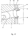
- Figures 15 to 17 show a further version of the housing seat and the annular sealing element 40; the solution of figures 15-17 is particularly suitable if the bush 30 is of small diameter or has a cylindrical wall of reduced thickness compared to previous solutions; again in figures 15-17 the same reference numbers as in the previous figures have been used to indicate similar or equivalent parts.
- the housing seat for the annular sealing element 40 is configured by a cross hole of the bush 30, having a greater diameter than the mixing chamber 11; as shown in figure 17 , the sealing element 40 extends on both outer sides of the bush 30, both towards the delivering conduit 12 and towards the contact interface 30.1 between bush 30 and body 10 of the apparatus.
- arch-shaped grooves 45 are provided in the latter, into which the resin can penetrate, forming corresponding anchoring toothings 46 shown in figure 17 ; in all cases, the toothings 46 prevent the resin from possibly running when dragged by the valve member 13.
- the angular extent, the thickness and depth of the arch-shaped grooves 45 can vary according to the needs and dimensions of the bush 30.
- the grooves 45 have a depth that gradually decreases one end to the other end; other forms of grooves 45 are of course possible.
Landscapes
- Engineering & Computer Science (AREA)
- Mechanical Engineering (AREA)
- Chemical & Material Sciences (AREA)
- Organic Chemistry (AREA)
- Chemical Kinetics & Catalysis (AREA)
- Processing And Handling Of Plastics And Other Materials For Molding In General (AREA)
- Injection Moulding Of Plastics Or The Like (AREA)
Applications Claiming Priority (1)
| Application Number | Priority Date | Filing Date | Title |
|---|---|---|---|
| IT000216A ITMI20130216A1 (it) | 2013-02-15 | 2013-02-15 | Metodo e apparecchiatura di miscelazione ad alta pressione con tenuta autorigenerante |
Publications (3)
| Publication Number | Publication Date |
|---|---|
| EP2767376A1 EP2767376A1 (en) | 2014-08-20 |
| EP2767376B1 EP2767376B1 (en) | 2015-10-14 |
| EP2767376B2 true EP2767376B2 (en) | 2019-04-03 |
Family
ID=47997667
Family Applications (1)
| Application Number | Title | Priority Date | Filing Date |
|---|---|---|---|
| EP14155160.6A Active EP2767376B2 (en) | 2013-02-15 | 2014-02-14 | Method and high-pressure mixing apparatus with self-regenerating seal |
Country Status (4)
| Country | Link |
|---|---|
| US (2) | US9308512B2 (it) |
| EP (1) | EP2767376B2 (it) |
| JP (1) | JP2014156118A (it) |
| IT (1) | ITMI20130216A1 (it) |
Families Citing this family (7)
| Publication number | Priority date | Publication date | Assignee | Title |
|---|---|---|---|---|
| ITMI20130216A1 (it) * | 2013-02-15 | 2014-08-16 | Afros Spa | Metodo e apparecchiatura di miscelazione ad alta pressione con tenuta autorigenerante |
| ITMI20132189A1 (it) * | 2013-12-23 | 2015-06-24 | Afros Spa | Metodo e apparecchiatura di miscelazione ad alta pressione per la co-iniezione di componenti polimerici |
| CN105922590B (zh) * | 2016-06-01 | 2019-04-09 | 深圳万为智能制造科技有限公司 | 3d打印用风嘴及具有风嘴的多通道伸缩喷嘴阀 |
| CN106079434B (zh) * | 2016-06-01 | 2019-04-12 | 深圳万为智能制造科技有限公司 | 3d打印用打印头、控制系统、3d打印机及打印方法 |
| IT201800010844A1 (it) * | 2018-12-05 | 2020-06-05 | Afros Spa | Elemento a guarnizione di tenuta per un’apparecchiatura di miscelazione, metodo di ottenimento ed applicazione dello stesso e relativa attrezzatura speciale di montaggio. |
| IT201900004603A1 (it) * | 2019-03-27 | 2020-09-27 | Afros Spa | Dispositivo di miscelazione ad alta pressione con condotto di erogazione in singolo pezzo |
| IT201900004609A1 (it) | 2019-03-27 | 2020-09-27 | Afros Spa | Dispositivo di miscelazione ad alta pressione con condotto di erogazione autopulente sensorizzato. |
Citations (1)
| Publication number | Priority date | Publication date | Assignee | Title |
|---|---|---|---|---|
| DE2616010A1 (de) † | 1976-04-12 | 1977-10-20 | Elastogran Gmbh | Vorrichtung zum mischen von mindestens zwei kunststoffkomponenten, insbesondere polyurethan |
Family Cites Families (18)
| Publication number | Priority date | Publication date | Assignee | Title |
|---|---|---|---|---|
| FR1376485A (fr) * | 1963-01-17 | 1964-10-31 | Buse d'admission pour mélangeurs | |
| BE779971R (fr) | 1971-04-10 | 1972-06-16 | Krauss Maffei Ag | Appareil pour l'amorcage et la preparation d'un melange de deuxou de plusieurs constituants synthetiques dans la cavite de moulage d'un |
| IT1109997B (it) | 1978-03-09 | 1985-12-23 | Afros Srl | Testa per la miscelazione e l'eiezione di componenti liquidi interagenti per lo stampaggio di materiali plastici |
| DE3111957A1 (de) * | 1981-03-26 | 1982-10-07 | Maschinenfabrik Hennecke Gmbh, 5090 Leverkusen | Einrichtung zum herstellen eines schaumstoff oder massivstoff bildenden fliessfaehigen reaktionsgemisches aus mindestens zwei fliessfaehigen komponenten |
| DE3120482C2 (de) * | 1981-05-22 | 1985-05-30 | Krauss-Maffei AG, 8000 München | Vorrichtung zum Herstellen eines insbesondere chemisch reaktionsfähigen Kunststoffgemisches und zum Zuleiten desselben zu einer Form |
| DE3418522A1 (de) * | 1984-05-18 | 1985-11-21 | Elastogran Maschinenbau GmbH, 2844 Lemförde | Vorrichtung zum mischen von mehrkomponentenkunststoffen, insbesondere polyurethan |
| EP0196345B2 (de) * | 1985-04-01 | 1994-04-27 | Krauss-Maffei Aktiengesellschaft | Verfahren und Vorrichtung zum Herstellen von Zellschaum |
| DE3521236A1 (de) * | 1985-06-13 | 1986-12-18 | IBW Ingenieur-Büro Woitzel GmbH, 4530 Ibbenbüren | Mischkopf zum vermischen zumindest zweier kunststoff bildender komponenten |
| ATE57649T1 (de) * | 1986-08-16 | 1990-11-15 | Woitzel Ingbuero Ibw | Mischkopf zum vermischen zumindest zweier kunststoff bildender komponenten. |
| DE8915329U1 (it) * | 1989-03-10 | 1990-04-12 | Krauss-Maffei Ag, 8000 Muenchen, De | |
| US5164162A (en) * | 1990-05-21 | 1992-11-17 | The Dow Chemical Company | Mixing head with sleeved quieting chamber |
| JP2812116B2 (ja) * | 1992-12-22 | 1998-10-22 | 豊田合成株式会社 | ミキシングヘッド |
| DE19515039C2 (de) * | 1995-04-24 | 1998-10-01 | Krauss Maffei Ag | Vorrichtung zum Mischen von wenigstens zwei chemisch reaktiven Kunststoffkomponenten |
| ITMI20022336A1 (it) * | 2002-11-05 | 2004-05-06 | Afros Spa | Procedimento ed apparecchiatura di miscelazione con |
| ITMI20062315A1 (it) * | 2006-11-30 | 2008-06-01 | Afros Spa | Metodo e apparecchiatura di miscelazione ad alta pressione con dispositivo di autolubrificazione raschiatura e flussaggio |
| DE102007023239B4 (de) * | 2007-05-18 | 2010-03-11 | Frimo Group Gmbh | Verfahren und Vorrichtung zur Herstellung eines Polyurethans aus zumindest zwei flüssigen Ausgangskomponenten |
| ITMI20130216A1 (it) * | 2013-02-15 | 2014-08-16 | Afros Spa | Metodo e apparecchiatura di miscelazione ad alta pressione con tenuta autorigenerante |
| ITMI20132189A1 (it) * | 2013-12-23 | 2015-06-24 | Afros Spa | Metodo e apparecchiatura di miscelazione ad alta pressione per la co-iniezione di componenti polimerici |
-
2013
- 2013-02-15 IT IT000216A patent/ITMI20130216A1/it unknown
-
2014
- 2014-02-12 US US14/178,505 patent/US9308512B2/en active Active
- 2014-02-14 JP JP2014027053A patent/JP2014156118A/ja active Pending
- 2014-02-14 EP EP14155160.6A patent/EP2767376B2/en active Active
-
2015
- 2015-11-30 US US14/953,541 patent/US9731267B2/en active Active
Patent Citations (1)
| Publication number | Priority date | Publication date | Assignee | Title |
|---|---|---|---|---|
| DE2616010A1 (de) † | 1976-04-12 | 1977-10-20 | Elastogran Gmbh | Vorrichtung zum mischen von mindestens zwei kunststoffkomponenten, insbesondere polyurethan |
Also Published As
| Publication number | Publication date |
|---|---|
| US20140234167A1 (en) | 2014-08-21 |
| US9308512B2 (en) | 2016-04-12 |
| EP2767376A1 (en) | 2014-08-20 |
| EP2767376B1 (en) | 2015-10-14 |
| US20160082407A1 (en) | 2016-03-24 |
| JP2014156118A (ja) | 2014-08-28 |
| ITMI20130216A1 (it) | 2014-08-16 |
| US9731267B2 (en) | 2017-08-15 |
Similar Documents
| Publication | Publication Date | Title |
|---|---|---|
| EP2767376B2 (en) | Method and high-pressure mixing apparatus with self-regenerating seal | |
| US3945569A (en) | Foam dispensing apparatus | |
| EP2233268B1 (en) | High-pressure mixing apparatus, with a scraping device | |
| EP0879685B1 (en) | Self-cleaning, mixing apparatus and method for the production of polyurethane mixtures | |
| EP0740987B1 (en) | Solvent flush reaction injection molding mixhead | |
| US10293361B2 (en) | Cartridge for viscous-material dispenser | |
| US20090071974A1 (en) | Liquid delivery method and apparatus | |
| CN211659888U (zh) | 具有单件输送管道的高压混合装置 | |
| KR20120085784A (ko) | 정전 도장기용의 도료 카트리지의 세정 방법 및 도료 백 | |
| EP3663063B1 (en) | Seal gasket element for a mixing apparatus and method for obtaining and applying the same | |
| KR20120072375A (ko) | 정전 도장기용의 도료 카트리지 및 이것을 포함하는 정전 도장기 | |
| KR100922457B1 (ko) | 화학반응에 의해 발생된 물질의 분배장치 | |
| KR100478342B1 (ko) | 공작기계의 절삭액 공급장치 | |
| KR200170956Y1 (ko) | 폴리우레탄 고압발포기의 믹싱헤드뭉치 | |
| EP2274568B1 (en) | Cleaning fluid cartridge | |
| JPH034020B2 (it) | ||
| JPS63222825A (ja) | 反応射出成形機の混合ヘツド |
Legal Events
| Date | Code | Title | Description |
|---|---|---|---|
| PUAI | Public reference made under article 153(3) epc to a published international application that has entered the european phase |
Free format text: ORIGINAL CODE: 0009012 |
|
| 17P | Request for examination filed |
Effective date: 20140214 |
|
| AK | Designated contracting states |
Kind code of ref document: A1 Designated state(s): AL AT BE BG CH CY CZ DE DK EE ES FI FR GB GR HR HU IE IS IT LI LT LU LV MC MK MT NL NO PL PT RO RS SE SI SK SM TR |
|
| AX | Request for extension of the european patent |
Extension state: BA ME |
|
| R17P | Request for examination filed (corrected) |
Effective date: 20150219 |
|
| RBV | Designated contracting states (corrected) |
Designated state(s): AL AT BE BG CH CY CZ DE DK EE ES FI FR GB GR HR HU IE IS IT LI LT LU LV MC MK MT NL NO PL PT RO RS SE SI SK SM TR |
|
| GRAP | Despatch of communication of intention to grant a patent |
Free format text: ORIGINAL CODE: EPIDOSNIGR1 |
|
| RIC1 | Information provided on ipc code assigned before grant |
Ipc: B29C 67/24 20060101ALI20150409BHEP Ipc: B29B 7/76 20060101AFI20150409BHEP Ipc: B29C 44/12 20060101ALI20150409BHEP Ipc: B29B 7/80 20060101ALI20150409BHEP |
|
| INTG | Intention to grant announced |
Effective date: 20150505 |
|
| GRAS | Grant fee paid |
Free format text: ORIGINAL CODE: EPIDOSNIGR3 |
|
| GRAA | (expected) grant |
Free format text: ORIGINAL CODE: 0009210 |
|
| AK | Designated contracting states |
Kind code of ref document: B1 Designated state(s): AL AT BE BG CH CY CZ DE DK EE ES FI FR GB GR HR HU IE IS IT LI LT LU LV MC MK MT NL NO PL PT RO RS SE SI SK SM TR |
|
| REG | Reference to a national code |
Ref country code: GB Ref legal event code: FG4D |
|
| REG | Reference to a national code |
Ref country code: AT Ref legal event code: REF Ref document number: 754767 Country of ref document: AT Kind code of ref document: T Effective date: 20151015 Ref country code: CH Ref legal event code: EP |
|
| REG | Reference to a national code |
Ref country code: NL Ref legal event code: MP Effective date: 20151014 |
|
| REG | Reference to a national code |
Ref country code: IE Ref legal event code: FG4D |
|
| REG | Reference to a national code |
Ref country code: DE Ref legal event code: R096 Ref document number: 602014000314 Country of ref document: DE |
|
| REG | Reference to a national code |
Ref country code: LT Ref legal event code: MG4D |
|
| REG | Reference to a national code |
Ref country code: AT Ref legal event code: MK05 Ref document number: 754767 Country of ref document: AT Kind code of ref document: T Effective date: 20151014 |
|
| PG25 | Lapsed in a contracting state [announced via postgrant information from national office to epo] |
Ref country code: NL Free format text: LAPSE BECAUSE OF FAILURE TO SUBMIT A TRANSLATION OF THE DESCRIPTION OR TO PAY THE FEE WITHIN THE PRESCRIBED TIME-LIMIT Effective date: 20151014 Ref country code: NO Free format text: LAPSE BECAUSE OF FAILURE TO SUBMIT A TRANSLATION OF THE DESCRIPTION OR TO PAY THE FEE WITHIN THE PRESCRIBED TIME-LIMIT Effective date: 20160114 Ref country code: LT Free format text: LAPSE BECAUSE OF FAILURE TO SUBMIT A TRANSLATION OF THE DESCRIPTION OR TO PAY THE FEE WITHIN THE PRESCRIBED TIME-LIMIT Effective date: 20151014 Ref country code: IS Free format text: LAPSE BECAUSE OF FAILURE TO SUBMIT A TRANSLATION OF THE DESCRIPTION OR TO PAY THE FEE WITHIN THE PRESCRIBED TIME-LIMIT Effective date: 20160214 Ref country code: HR Free format text: LAPSE BECAUSE OF FAILURE TO SUBMIT A TRANSLATION OF THE DESCRIPTION OR TO PAY THE FEE WITHIN THE PRESCRIBED TIME-LIMIT Effective date: 20151014 Ref country code: ES Free format text: LAPSE BECAUSE OF FAILURE TO SUBMIT A TRANSLATION OF THE DESCRIPTION OR TO PAY THE FEE WITHIN THE PRESCRIBED TIME-LIMIT Effective date: 20151014 |
|
| PG25 | Lapsed in a contracting state [announced via postgrant information from national office to epo] |
Ref country code: BE Free format text: LAPSE BECAUSE OF NON-PAYMENT OF DUE FEES Effective date: 20160229 Ref country code: PL Free format text: LAPSE BECAUSE OF FAILURE TO SUBMIT A TRANSLATION OF THE DESCRIPTION OR TO PAY THE FEE WITHIN THE PRESCRIBED TIME-LIMIT Effective date: 20151014 Ref country code: FI Free format text: LAPSE BECAUSE OF FAILURE TO SUBMIT A TRANSLATION OF THE DESCRIPTION OR TO PAY THE FEE WITHIN THE PRESCRIBED TIME-LIMIT Effective date: 20151014 Ref country code: PT Free format text: LAPSE BECAUSE OF FAILURE TO SUBMIT A TRANSLATION OF THE DESCRIPTION OR TO PAY THE FEE WITHIN THE PRESCRIBED TIME-LIMIT Effective date: 20160215 Ref country code: RS Free format text: LAPSE BECAUSE OF FAILURE TO SUBMIT A TRANSLATION OF THE DESCRIPTION OR TO PAY THE FEE WITHIN THE PRESCRIBED TIME-LIMIT Effective date: 20151014 Ref country code: LV Free format text: LAPSE BECAUSE OF FAILURE TO SUBMIT A TRANSLATION OF THE DESCRIPTION OR TO PAY THE FEE WITHIN THE PRESCRIBED TIME-LIMIT Effective date: 20151014 Ref country code: AT Free format text: LAPSE BECAUSE OF FAILURE TO SUBMIT A TRANSLATION OF THE DESCRIPTION OR TO PAY THE FEE WITHIN THE PRESCRIBED TIME-LIMIT Effective date: 20151014 Ref country code: SE Free format text: LAPSE BECAUSE OF FAILURE TO SUBMIT A TRANSLATION OF THE DESCRIPTION OR TO PAY THE FEE WITHIN THE PRESCRIBED TIME-LIMIT Effective date: 20151014 Ref country code: GR Free format text: LAPSE BECAUSE OF FAILURE TO SUBMIT A TRANSLATION OF THE DESCRIPTION OR TO PAY THE FEE WITHIN THE PRESCRIBED TIME-LIMIT Effective date: 20160115 |
|
| REG | Reference to a national code |
Ref country code: DE Ref legal event code: R026 Ref document number: 602014000314 Country of ref document: DE |
|
| PLBI | Opposition filed |
Free format text: ORIGINAL CODE: 0009260 |
|
| PG25 | Lapsed in a contracting state [announced via postgrant information from national office to epo] |
Ref country code: CZ Free format text: LAPSE BECAUSE OF FAILURE TO SUBMIT A TRANSLATION OF THE DESCRIPTION OR TO PAY THE FEE WITHIN THE PRESCRIBED TIME-LIMIT Effective date: 20151014 |
|
| PLAX | Notice of opposition and request to file observation + time limit sent |
Free format text: ORIGINAL CODE: EPIDOSNOBS2 |
|
| 26 | Opposition filed |
Opponent name: KRAUSSMAFFEI TECHNOLOGIES GMBH Effective date: 20160714 |
|
| PG25 | Lapsed in a contracting state [announced via postgrant information from national office to epo] |
Ref country code: EE Free format text: LAPSE BECAUSE OF FAILURE TO SUBMIT A TRANSLATION OF THE DESCRIPTION OR TO PAY THE FEE WITHIN THE PRESCRIBED TIME-LIMIT Effective date: 20151014 Ref country code: RO Free format text: LAPSE BECAUSE OF FAILURE TO SUBMIT A TRANSLATION OF THE DESCRIPTION OR TO PAY THE FEE WITHIN THE PRESCRIBED TIME-LIMIT Effective date: 20151014 Ref country code: DK Free format text: LAPSE BECAUSE OF FAILURE TO SUBMIT A TRANSLATION OF THE DESCRIPTION OR TO PAY THE FEE WITHIN THE PRESCRIBED TIME-LIMIT Effective date: 20151014 Ref country code: SK Free format text: LAPSE BECAUSE OF FAILURE TO SUBMIT A TRANSLATION OF THE DESCRIPTION OR TO PAY THE FEE WITHIN THE PRESCRIBED TIME-LIMIT Effective date: 20151014 Ref country code: SM Free format text: LAPSE BECAUSE OF FAILURE TO SUBMIT A TRANSLATION OF THE DESCRIPTION OR TO PAY THE FEE WITHIN THE PRESCRIBED TIME-LIMIT Effective date: 20151014 |
|
| PG25 | Lapsed in a contracting state [announced via postgrant information from national office to epo] |
Ref country code: MC Free format text: LAPSE BECAUSE OF FAILURE TO SUBMIT A TRANSLATION OF THE DESCRIPTION OR TO PAY THE FEE WITHIN THE PRESCRIBED TIME-LIMIT Effective date: 20151014 Ref country code: LU Free format text: LAPSE BECAUSE OF FAILURE TO SUBMIT A TRANSLATION OF THE DESCRIPTION OR TO PAY THE FEE WITHIN THE PRESCRIBED TIME-LIMIT Effective date: 20160214 |
|
| REG | Reference to a national code |
Ref country code: FR Ref legal event code: ST Effective date: 20161028 |
|
| PG25 | Lapsed in a contracting state [announced via postgrant information from national office to epo] |
Ref country code: SI Free format text: LAPSE BECAUSE OF FAILURE TO SUBMIT A TRANSLATION OF THE DESCRIPTION OR TO PAY THE FEE WITHIN THE PRESCRIBED TIME-LIMIT Effective date: 20151014 |
|
| REG | Reference to a national code |
Ref country code: IE Ref legal event code: MM4A |
|
| PLBB | Reply of patent proprietor to notice(s) of opposition received |
Free format text: ORIGINAL CODE: EPIDOSNOBS3 |
|
| PG25 | Lapsed in a contracting state [announced via postgrant information from national office to epo] |
Ref country code: BE Free format text: LAPSE BECAUSE OF FAILURE TO SUBMIT A TRANSLATION OF THE DESCRIPTION OR TO PAY THE FEE WITHIN THE PRESCRIBED TIME-LIMIT Effective date: 20151014 |
|
| PG25 | Lapsed in a contracting state [announced via postgrant information from national office to epo] |
Ref country code: IE Free format text: LAPSE BECAUSE OF NON-PAYMENT OF DUE FEES Effective date: 20160214 Ref country code: FR Free format text: LAPSE BECAUSE OF NON-PAYMENT OF DUE FEES Effective date: 20160229 |
|
| PLAY | Examination report in opposition despatched + time limit |
Free format text: ORIGINAL CODE: EPIDOSNORE2 |
|
| PG25 | Lapsed in a contracting state [announced via postgrant information from national office to epo] |
Ref country code: MT Free format text: LAPSE BECAUSE OF FAILURE TO SUBMIT A TRANSLATION OF THE DESCRIPTION OR TO PAY THE FEE WITHIN THE PRESCRIBED TIME-LIMIT Effective date: 20151014 |
|
| PLBC | Reply to examination report in opposition received |
Free format text: ORIGINAL CODE: EPIDOSNORE3 |
|
| REG | Reference to a national code |
Ref country code: CH Ref legal event code: PL |
|
| PG25 | Lapsed in a contracting state [announced via postgrant information from national office to epo] |
Ref country code: LI Free format text: LAPSE BECAUSE OF NON-PAYMENT OF DUE FEES Effective date: 20170228 Ref country code: CH Free format text: LAPSE BECAUSE OF NON-PAYMENT OF DUE FEES Effective date: 20170228 |
|
| PG25 | Lapsed in a contracting state [announced via postgrant information from national office to epo] |
Ref country code: CY Free format text: LAPSE BECAUSE OF FAILURE TO SUBMIT A TRANSLATION OF THE DESCRIPTION OR TO PAY THE FEE WITHIN THE PRESCRIBED TIME-LIMIT Effective date: 20151014 Ref country code: HU Free format text: LAPSE BECAUSE OF FAILURE TO SUBMIT A TRANSLATION OF THE DESCRIPTION OR TO PAY THE FEE WITHIN THE PRESCRIBED TIME-LIMIT; INVALID AB INITIO Effective date: 20140214 |
|
| PG25 | Lapsed in a contracting state [announced via postgrant information from national office to epo] |
Ref country code: MK Free format text: LAPSE BECAUSE OF FAILURE TO SUBMIT A TRANSLATION OF THE DESCRIPTION OR TO PAY THE FEE WITHIN THE PRESCRIBED TIME-LIMIT Effective date: 20151014 Ref country code: TR Free format text: LAPSE BECAUSE OF FAILURE TO SUBMIT A TRANSLATION OF THE DESCRIPTION OR TO PAY THE FEE WITHIN THE PRESCRIBED TIME-LIMIT Effective date: 20151014 Ref country code: MT Free format text: LAPSE BECAUSE OF FAILURE TO SUBMIT A TRANSLATION OF THE DESCRIPTION OR TO PAY THE FEE WITHIN THE PRESCRIBED TIME-LIMIT Effective date: 20160229 |
|
| PG25 | Lapsed in a contracting state [announced via postgrant information from national office to epo] |
Ref country code: BG Free format text: LAPSE BECAUSE OF FAILURE TO SUBMIT A TRANSLATION OF THE DESCRIPTION OR TO PAY THE FEE WITHIN THE PRESCRIBED TIME-LIMIT Effective date: 20151014 |
|
| GBPC | Gb: european patent ceased through non-payment of renewal fee |
Effective date: 20180214 |
|
| PG25 | Lapsed in a contracting state [announced via postgrant information from national office to epo] |
Ref country code: AL Free format text: LAPSE BECAUSE OF FAILURE TO SUBMIT A TRANSLATION OF THE DESCRIPTION OR TO PAY THE FEE WITHIN THE PRESCRIBED TIME-LIMIT Effective date: 20151014 |
|
| PG25 | Lapsed in a contracting state [announced via postgrant information from national office to epo] |
Ref country code: GB Free format text: LAPSE BECAUSE OF NON-PAYMENT OF DUE FEES Effective date: 20180214 |
|
| PUAH | Patent maintained in amended form |
Free format text: ORIGINAL CODE: 0009272 |
|
| STAA | Information on the status of an ep patent application or granted ep patent |
Free format text: STATUS: PATENT MAINTAINED AS AMENDED |
|
| 27A | Patent maintained in amended form |
Effective date: 20190403 |
|
| AK | Designated contracting states |
Kind code of ref document: B2 Designated state(s): AL AT BE BG CH CY CZ DE DK EE ES FI FR GB GR HR HU IE IS IT LI LT LU LV MC MK MT NL NO PL PT RO RS SE SI SK SM TR |
|
| REG | Reference to a national code |
Ref country code: DE Ref legal event code: R102 Ref document number: 602014000314 Country of ref document: DE |
|
| PGFP | Annual fee paid to national office [announced via postgrant information from national office to epo] |
Ref country code: IT Payment date: 20230221 Year of fee payment: 10 |
|
| PGFP | Annual fee paid to national office [announced via postgrant information from national office to epo] |
Ref country code: DE Payment date: 20240228 Year of fee payment: 11 |