EP2767342A2 - Verfahren zur grössenmässigen klassifizierung von polydispersen materialien und vorrichtung zur durchführung des verfahrens - Google Patents
Verfahren zur grössenmässigen klassifizierung von polydispersen materialien und vorrichtung zur durchführung des verfahrens Download PDFInfo
- Publication number
- EP2767342A2 EP2767342A2 EP20120811251 EP12811251A EP2767342A2 EP 2767342 A2 EP2767342 A2 EP 2767342A2 EP 20120811251 EP20120811251 EP 20120811251 EP 12811251 A EP12811251 A EP 12811251A EP 2767342 A2 EP2767342 A2 EP 2767342A2
- Authority
- EP
- European Patent Office
- Prior art keywords
- classification
- rotor
- channel
- liquid
- output
- Prior art date
- Legal status (The legal status is an assumption and is not a legal conclusion. Google has not performed a legal analysis and makes no representation as to the accuracy of the status listed.)
- Withdrawn
Links
- 239000000463 material Substances 0.000 title claims abstract description 138
- 238000000034 method Methods 0.000 title claims abstract description 42
- 239000002245 particle Substances 0.000 claims abstract description 113
- 239000007788 liquid Substances 0.000 claims abstract description 96
- 230000009471 action Effects 0.000 claims abstract description 35
- 239000012530 fluid Substances 0.000 claims description 53
- 239000000725 suspension Substances 0.000 claims description 30
- 238000002372 labelling Methods 0.000 claims description 28
- 239000011344 liquid material Substances 0.000 claims description 9
- 230000008021 deposition Effects 0.000 claims description 8
- 239000011236 particulate material Substances 0.000 claims description 5
- 239000000843 powder Substances 0.000 abstract description 4
- 238000007599 discharging Methods 0.000 abstract description 3
- 238000005516 engineering process Methods 0.000 abstract description 2
- 239000002002 slurry Substances 0.000 description 53
- 238000000926 separation method Methods 0.000 description 37
- 238000004364 calculation method Methods 0.000 description 8
- 230000008569 process Effects 0.000 description 4
- 230000008707 rearrangement Effects 0.000 description 3
- 239000007858 starting material Substances 0.000 description 3
- 230000007704 transition Effects 0.000 description 3
- GWEVSGVZZGPLCZ-UHFFFAOYSA-N Titan oxide Chemical compound O=[Ti]=O GWEVSGVZZGPLCZ-UHFFFAOYSA-N 0.000 description 2
- 238000010276 construction Methods 0.000 description 2
- 238000010586 diagram Methods 0.000 description 2
- 238000009792 diffusion process Methods 0.000 description 2
- 230000000694 effects Effects 0.000 description 2
- 239000010419 fine particle Substances 0.000 description 2
- 230000004907 flux Effects 0.000 description 2
- 238000002955 isolation Methods 0.000 description 2
- 229910052580 B4C Inorganic materials 0.000 description 1
- 229910052582 BN Inorganic materials 0.000 description 1
- PZNSFCLAULLKQX-UHFFFAOYSA-N Boron nitride Chemical compound N#B PZNSFCLAULLKQX-UHFFFAOYSA-N 0.000 description 1
- 239000003082 abrasive agent Substances 0.000 description 1
- 230000015572 biosynthetic process Effects 0.000 description 1
- INAHAJYZKVIDIZ-UHFFFAOYSA-N boron carbide Chemical compound B12B3B4C32B41 INAHAJYZKVIDIZ-UHFFFAOYSA-N 0.000 description 1
- 239000010431 corundum Substances 0.000 description 1
- 229910052593 corundum Inorganic materials 0.000 description 1
- 239000010432 diamond Substances 0.000 description 1
- 229910003460 diamond Inorganic materials 0.000 description 1
- 239000006185 dispersion Substances 0.000 description 1
- 230000005484 gravity Effects 0.000 description 1
- 239000000203 mixture Substances 0.000 description 1
- 230000035515 penetration Effects 0.000 description 1
- 239000002244 precipitate Substances 0.000 description 1
- 230000009467 reduction Effects 0.000 description 1
- 229910010271 silicon carbide Inorganic materials 0.000 description 1
- HBMJWWWQQXIZIP-UHFFFAOYSA-N silicon carbide Chemical compound [Si+]#[C-] HBMJWWWQQXIZIP-UHFFFAOYSA-N 0.000 description 1
- 239000004408 titanium dioxide Substances 0.000 description 1
- UONOETXJSWQNOL-UHFFFAOYSA-N tungsten carbide Chemical compound [W+]#[C-] UONOETXJSWQNOL-UHFFFAOYSA-N 0.000 description 1
- 238000011144 upstream manufacturing Methods 0.000 description 1
- XLYOFNOQVPJJNP-UHFFFAOYSA-N water Substances O XLYOFNOQVPJJNP-UHFFFAOYSA-N 0.000 description 1
Images



Classifications
-
- B—PERFORMING OPERATIONS; TRANSPORTING
- B03—SEPARATION OF SOLID MATERIALS USING LIQUIDS OR USING PNEUMATIC TABLES OR JIGS; MAGNETIC OR ELECTROSTATIC SEPARATION OF SOLID MATERIALS FROM SOLID MATERIALS OR FLUIDS; SEPARATION BY HIGH-VOLTAGE ELECTRIC FIELDS
- B03B—SEPARATING SOLID MATERIALS USING LIQUIDS OR USING PNEUMATIC TABLES OR JIGS
- B03B5/00—Washing granular, powdered or lumpy materials; Wet separating
- B03B5/28—Washing granular, powdered or lumpy materials; Wet separating by sink-float separation
- B03B5/30—Washing granular, powdered or lumpy materials; Wet separating by sink-float separation using heavy liquids or suspensions
- B03B5/32—Washing granular, powdered or lumpy materials; Wet separating by sink-float separation using heavy liquids or suspensions using centrifugal force
Definitions
- the invention relates to the field of powder technology, specifically to methods for size classification of polydispersed materials, e.g. materials such as diamond, silicon carbide, tungsten carbide, boron carbide, corundum, boron nitride, titanium dioxide, microcalcite etc.
- polydispersed materials e.g. materials such as diamond, silicon carbide, tungsten carbide, boron carbide, corundum, boron nitride, titanium dioxide, microcalcite etc.
- the method consists in that the initial mixture is water jet containing several fractions of abrasive particles is sent with a constant volume flow in a direction opposite to the forces of the gravitational field. As part of the lifting the part of flow merges. On the basis of the law of hydrodynamics speed of homogeneous particles under the influence of the field force is proportional to the square of its diameter. Particles larger than a predetermined size (in which the velocity of the stationary liquid layer over a linear flow rate of moving opposite the gravitational force field) move in the direction of the force field and makes the appropriate flow. Particles smaller than a predetermined size are moved to the opposite direction to the gravitational field, and makes the flow of the labeling zone. In the process of separation of the two streams are formed: one containing only particles smaller than a predetermined size (the size is mainly determined by the flow rate), and the second containing larger particles of a given size of the particles and smaller than the predetermined size.
- the method allows preliminary separation of abrasives having a particle size larger than 10 microns in the continuous mode.
- complete separation of the fine and coarse fraction by this method is not due to an inevitable and considerable (up to 90%) entering the flow of coarse fraction from the fine particles.
- this method is virtually impossible to classify materials micron (particle size less than 10 microns) and submicron (particle size less than 1 micron) range.
- Closest to the present invention include a method of classification of polydispersed materials and device for its implementation Patent RU 2130806 .
- the process is fed through said inlet into the slurry flow channel classification polydispersed material "slurry feed stream separation polydispersed material into two streams, the first of which, with particles of a predetermined size (separated fraction) is withdrawn in the direction opposite the action of the centrifugal force field through the first output and a second stream suspension with particles of size greater than a predetermined which is output in the direction of the centrifugal force field through the second exit.
- Device for implementing the method comprises a hollow shaft with a rotation axis, formed as a cylindrical container, means for supplying suspension to the rotor polydispersed material slurry outlet means with a predetermined fraction of the selected size, means for removal of slurry from a coarse fraction and a rotor assembly mounted in the labeling, to form a a rotor assembly over said material deposition chambers connected with the liquid flow outlet means and the cavity along the axis of the rotor.
- the node classification includes at least one channel classification perpendicular to the axis of rotation of the rotor, having in the direction of the axis of rotation of the first rotor outlet open into said cavity of the rotor, and a second outlet with a nozzle mounted thereon, which outlet diameter much smaller than the first outlet.
- the nozzle is connected with means to discharge the slurry larger fraction. Between the outputs of the channel formed in the inlet flow of slurry to polydispersed materials, wherein said inlet is connected with means for supplying suspension to the rotor inlet passage polydispersed materials formed in said node at an angle to the separation channel.
- the method is performed as follows. In separating the inclined channel input channel is fed liquid flow polydispersed material (slurry flow polydispersed material) in the direction of the centrifugal force field with the specified flow rate. Due to the size of the outlet nozzle at the second output, which is considerably smaller than the first outlet, the second outlet flow resistance created by the hydraulic suspension.
- liquid flow polydispersed material slurry flow polydispersed material
- Feed slurry with particles of a predetermined size, stemming from the first outlet (first slurry flow) is supplied to the deposition chamber where it is isolated from a given material.
- the liquid stream is separated from the material stream is combined with the slurry, which flows through the nozzle and recycled to the suspension tank with the source from which it is again supplied to the device for further classification of the classification.
- the initial slurry is circulated in the classification zone and out of the fine fraction of the powder is drawn, which is deposited in the rotor, namely, a deposition chamber in the rotor arranged on the separating assembly.
- polydispersed material may be divided into any number of fractions.
- the separation process is characterized by low productivity, since a complete separation of the starting material is carried out only for a few cycles of the passage of the slurry flow flowing from the nozzle as part of a predetermined particle size separation flows through the nozzle channel.
- Volumetric flow rate flowing through the nozzle is constant and depends on the diameter of the nozzle, the magnitude of the centrifugal force and the magnitude of the fluid before the nozzle layer (this value is determined by the structural elements of the rotor).
- the volumetric flow rate and the fraction is adjusted depending on the desired size of the particles displaced by the.
- flow rates of the two streams are similar in magnitude, i.e. approximately half the initial flow outwards out of the rotor together with small particles. Because of this need to return back to this stream classification for re-allocation of a fine fraction. For complete isolation requires 20-30 cycles, which significantly limits the performance of the known method and apparatus.
- the present invention is to eliminate any particles the size of which is equal to or less than a predetermined, in a stream with a larger fraction arising from the labeling zone in the direction of action of centrifugal forces and, thus, provide for the passage of one cycle of the classification zone selection of a polydispersed source a predetermined size of the particulate material in order to increase the effectiveness of the method and device size classification polydispersed materials.
- the method comprises feeding to the labeling zone polydispersed material in a fluid stream with a predetermined volume flow rate , establishing a classification zone effluent flowing in a direction against the action of the centrifugal field of forces at a speed close to the speed of movement of the material particles of a given size under the influence of the centrifugal field and including said particles of a predetermined material size , the output of said classification zone effluent stream in a direction against the action of the centrifugal force field , the output of the classification zone of the material particles which are larger than a predetermined , in the direction of the centrifugal force field , according to the present invention, the labeling zone at a portion located at the course of action of the centrifugal forces of the entrance of a polydispersed material is supplied with a predetermined volume flow rate , establishing a classification zone effluent flowing in a direction against the action of the centrifugal field of forces at a speed close to the speed of movement of the material particles of a given
- a liquid stream comprising a polydispersed particle material (supplied polydispersed suspension of the material), falling into the classification zone, under the influence of the additional net liquid flow is not split into two streams, as in the known solution, and is set against the direction of centrifugal force.
- Flow reversal occurs, including through the establishment of an additional liquid flow resistance at the outlet of the classification zone in the direction of the centrifugal forces.
- a predetermined particle size move along with the flow and the output from the labeling zone.
- polydispersed material supplied during one cycle i.e. one passageway classification zone is produced almost complete separation of mother predetermined fraction in a fairly narrow range, which provides high efficiency of the proposed method.
- the feed stream of clean liquid, without material in the classification zone to form a first liquid stream flowing in a direction against the action of the centrifugal force field and the incoming downstream of the output stream and a second liquid stream flowing in the direction of the centrifugal force field at said first liquid stream is formed so that its speed was close to the speed of movement of the material particles of a given size under the influence of the centrifugal field, with said second liquid stream comprises particles of material which are larger than a predetermined size.
- the first stream of clean liquid that flows in a direction against the centrifugal field affects the particles of a given size, displacing them towards the first exit. As a result, ingress of particles is eliminated, a predetermined size or smaller to the larger particle flow flowing in the direction of action of centrifugal forces.
- the combined output stream will also have a velocity close to the velocity of a given particle fraction, which provides a narrow range separation specify the material fractions, ie eliminates output particles of a given size in the direction of the centrifugal force field.
- volumetric flow rates supplied to the zone classification of fluid flows with a polydispersed material and pure liquid, without material were determined from the condition:
- volumetric flow ratio ensures that (or similar values), flow rate flowing in a direction against the action of a centrifugal force field to speed predetermined particle size by the action of a centrifugal field, namely, the combined output stream (feed fluid stream comprising particles the first material and the net flow of the liquid) and the first flow of clean liquid.
- the liquid material without (clear liquid) supplied to the classification zone at a portion upstream of the action of centrifugal force at a distance from the entrance of the feed slurry polydispersed material Thanks spacing inputs for feed streams provided by the formation of a laminar flow clean liquid that improves the efficiency of the separation.
- One way of implementing the method is to create zones in the classifying rotor in the form of a channel arranged perpendicular to the axis of rotor rotation and having arranged in series along the centrifugal force the first and second outputs and between the first inlet for supplying a flow of polydispersed liquid material and a second input for feeding unflavoured material disposed proximate to the second exit.
- the second outlet orifice creates a smaller diameter than the first.
- the channel portion to the second output of the first carry input of smaller diameter than the first section of the channel from the inlet to the first outlet.
- the length of the narrow portion of the channel to perform at least the diameter of the narrow channel and higher. It is necessary to calm the flow velocities of the moving parts on the channel and the equalization of the cross section.
- a device for classifying a polydispersed materials in a liquid medium containing a hollow shaft with an axis of rotation and in the form of a cylindrical vessel means for supplying to the rotor of polydispersed materials in the fluid stream, a first fluid outlet means with particles of a predetermined size, the second fluid outlet means with particles of larger size, and installed in the rotor assembly to form a classifying rotor in the cavity along its axis of rotation, connected to said first discharge means comprising at least one channel classification perpendicular to the axis of rotation of the rotor, having in the direction of the axis of rotation of the first rotor outlet open into said cavity of the rotor, and a second output coupled to said second discharge means, while the second exit orifice is less than the flow section of the first outlet to create the hydraulic resistance to fluid flow at the second output, a first input for supplying a polydispersed materials in the fluid stream, bred between said output and connected to said means for supplying
- the classification unit comprises a first and second input channels, respectively connecting the first second inputs to the respective supply means, said input channels are preferably made inclined classification channel towards the second exit.
- Sloping channels provide input to the zone classification feed streams under the action of the centrifugal field.
- the device comprises two or more of the classification channels. Large number of channels to improve performance of the device.
- the number of channels in the device defined by the structural features of the device depends on the dimensions of the device and the desired slurry streams, i.e. the volumes of polydispersed suspension of processed material.
- Such a variant of the device can be used for the separation of small amounts of material by volume, for example research.
- Size classification method polydispersed materials preferred embodiment shown in FIG. 1 , as follows.
- classification zone 1 Fig. 1
- Classification Area 1 is sequentially arranged along the first centrifugal force output 2 for the selected output stream pictures predetermined fraction i.e. the particles whose size lies within a predetermined range (the first stream of slurry) and a second outlet 3 for material flow to the particles whose size more specified.
- a first input-output 4 is for supplying liquid feed stream with polydispersed material and a second input 5 for supplying a liquid material without (clear liquid).
- the second outlet 3 create hydraulic flow resistance of the fluid flowing out by centrifugal force, for example by creating second outlet passage section 3 significantly smaller compared to the first flow section 2 and the width of the exit zone 1 classification.
- 5 through the second input is fed with a predetermined volume flow
- fluid flow 6 without material (clean fluid) through the first inlet 4 is supplied with a specified volumetric flow rate Q BX 7 fluid feedstream with polydispersed material (hereinafter referred to as "initial poly-dispersed slurry material).
- the liquid feed stream 7 supplied with polydispersed material into zone 1 of classification takes place by combining the first flow of clean liquid 8 forms the output stream 10, which flows in a direction opposite to the forces of the centrifugal field, and output classification of areas through the first outlet 2.
- Material particles, the velocity at which the centrifugal force is less than the velocity of the combined output stream 10 and stream 8 liquid medium move under the influence of the flow in the direction against the forces of the centrifugal field, along with the stream, and they are displaced from the labeling zone through the first outlet 2 .
- three zone classification formed slurry flow of material a first combined output stream 10 and stream 8 with a predetermined fraction of the selected material, the current field against the centrifugal forces arising, and through the first outlet 2 and the third slurry stream (stream 9 of liquid with particulate material, dimensions are larger than the specified), the current in the direction of the centrifugal force field and flowing through the second exit 3.
- Specifying, in particular, the angular velocity zone classification, i.e. a certain level of centrifugal force and the diameter of zone 1 classification, which in turn define the flow rate of the output 10 in zone 1 classification, provide dimensional classification poly particulate starting material, namely, selection of a polydispersed particle material with the size of the material in a predetermined range.
- first thread 8 of the clean fluid displaces the labeling zone 1 to exit the first material particles 2, which is less than a predetermined size and which fall within the stream larger particles, for example, by dispersion or sticking to the larger particles.
- the labeling zone feed polydispersed material during one cycle i.e. one pass classification zone is allocated to all the material particles of a given size.
- volumetric flow rates of input streams 6 and 7, supplied to the classification zone 1 via first and second inputs 4 and 5, respectively, and output volumetric flow rates of streams 10 and 9 through the first and second outputs 2 and 3 are determined from the condition: where:
- the narrow diameter portion 12 to receive 1.4 - 4.5 times smaller than the diameter of the wide portion 11, which reduces the consumption of clean liquid (stream 8), in 2 - 20 times as compared with the flow 10 in the wide portion 11 (on the basis of the conditions equal flow rates of 10 and 8 in the wide and narrow portions 11 and 12, respectively, the area classification) and 5-50% of the flow rate in the wide part 10.
- these parameters are selected by the known calculation and/or empirically based on the particular conditions of separating suspension, in particular depending on the type of material, concentration of the form of the integral curve of the particle size distribution of the initial suspension, which determines the ratio of small and large fractions on the border of separation.
- the length of the narrow part of the channel is set equal to or greater than its diameter.
- the process of the classification zone without separation not honor different diameters, as shown in Fig. 2 .
- the volume flow supplied substantially pure liquid 6 does not exceed 9 volume flow through the second flow outlet 3.
- fed into the classification zone of clean hydraulic fluid 6 creates the second output resistance is not 3, which reverses the original liquid stream 7 is fed via a first input with polydispersed material 4 in the direction against the effect of centrifugal forces.
- the classification zone is formed in the combined fluid output flow 10 flowing in a direction against the action of a centrifugal force field.
- This option can be used with understated quality requirements for separation and limited overall dimensions node separation.
- the device constructive second input can be rasplozhen almost immediately after the first entrance.
- This option can be used in more understated quality requirements for separation and limited overall dimensions node classification.
- Zone classification parameters can be calculated from the known mathematical dependences iterative method.
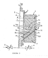
- FIG. 3 shown preferred embodiments of an apparatus for classifying polydispersed materials.
- Device shown at Fig. 1 comprises a hollow shaft 1 with the rotation axis 2, embodied in the form of a cylindrical vessel, means 3 to the rotor feeding polydispersed liquid material (slurry polydispersed material) directed means 4 to the rotor, without the fluid material (clear liquid), the liquid outlet means 5 with material particles of a given size (suspensions and the fraction of a given size), the means 6 for discharging the liquid material with the particles whose size is greater than a predetermined (slurry a coarse fraction).
- slurry polydispersed material slurry polydispersed material directed means 4 to the rotor, without the fluid material (clear liquid)
- the liquid outlet means 5 with material particles of a given size (suspensions and the fraction of a given size)
- the means 6 for discharging the liquid material with the particles whose size is greater than a predetermined (slurry a coarse fraction).
- Classifying unit 7 comprises at least one channel classification 71, two perpendicular axes of rotation of the rotor 1.
- Channel 71 has a first direction of rotation of the rotor output axis 72, open into the cavity 8 of the rotor 1, and a second outlet 73, aligned with the hole in the rotor, and for example, cross member 6 connected to drain slurry from the rotor with a larger fraction located between them a first input 74 for supplying slurry materials polydispersed and a second input 75 for the supply of clean liquid (without material) downstream of the action of the centrifugal forces is not spaced from the first entrance 74, preferably about 73 second outlet channel 71.
- a second output channel 73 is provided with means 71 to provide a reduction of its diameter, e.g., nozzle set, for example, in the hole wall of the rotor.
- structural embodiment second input device 75 may be located almost immediately after the first input 74.
- such an implementation may be advantageous for low requirements to the parameters of separation, and the limited dimensions of the node classification.
- the diameter 72 of the first exit channel 71 is a value interrelated with a volumetric flow combined output flow with a suspension of 9 selected pictures (the first stream of slurry), which in turn is defined by a capacity of the device.
- the hole diameter at the second output 73 is one of factors that determine the volumetric flow rate of the liquid medium Q (a second stream 11 of the slurry with particles of larger size than the defined range) g flowing through the second outlet 73 (the nozzle). Bore holes 73 on the second output and the second volumetric flow rate Q slurry through nozzle 11 can be calculated by the following relationship where
- the cone-shaped transition from the wide portion 711 to a narrow portion 712 prevents the deposition of coarser particles moving to the second outlet at the wall of the cone.
- the transition between the parts can be staged.
- At the same time on the interface will precipitate large particles of material that will form a streamlined surface.
- the possible separation of the large particle material which may close the nozzle.
- the diameters of the wide and narrow portions 711 and 712 define a channel 71 from the condition that the flow rates in the wide and narrow portions 711 and 712 channel 71.
- the length of the narrow part of the channel 712 is not less than 71 and preferably greater than its diameter to provide a laminar flow of fluid therein.
- the total length of the channel 71 classification should be minimal, as it allows the design to reduce the ratio of the centrifugal forces on the ground and second outputs.
- the first and second inlets 74 and 75 may have a circular shape as well as another example, in the form of slits. Wherein the first inlet 74 to be at the boundary of the narrow and wide portions 711 and 712 channels.
- the labeling assembly 7 comprises a first inlet duct 76, formed in said unit 7 at an angle to the channel 71 (in a direction toward the second outlet) and connected to the first input channel 71 and 74 with the means 3 for supplying the feed slurry to the rotor polydispersed material, a second input channel 77 formed in said unit 7 at an angle to the channel 71 (in a direction toward the second outlet), and connected to a second input channel 71 and 75 with means 4 for supplying clean liquid to the rotor.
- tilt angle of the input channels wherein said angle is selected from structural considerations.
- Did not sloping execution unit input channels for example, by performing the labeling of the cavities in the node connected to the channel classification. Especially, this is possible to enter the pure liquid, however, for slurry flow will require special measures to avoid stagnant zones along the flow path, in which material can accumulate and interfere with the flow.
- the means 3, 4 (shown in phantom) for supplying a suspension to the rotor 1 polydispersed materials and pure liquid may be used well-known structures, such as nozzles.
- Means 5, 6 (shown in phantom) O suspensions are channels through which the slurry flows by gravity by centrifugal force.
- the slurry accumulates in compendiums and pumped further known methods into the device for further processing.
- the second exit orifice 73 (outlet nozzle diameter) is less than the diameter of the narrowest part of the channel 712, the second outlet 73 creates a resistance to the incoming flow of hydraulic fluid, clean fluid flow is split into two streams, one of which, the first fluid stream 10 flowing in a direction opposite to the centrifugal force, and the second - in the direction of action of these forces.
- the first outlet slurry stream 9 which carries a first output 72 of a given size of particles of matter.
- Volumetric flow rates Q BX and are respectively supplied to the liquid channel 71 from the source material and polydispersed clean fluid and the rate of rotation of the rotor, depending on the structural characteristics of the device (the channel in the wide and narrow portions, the inner and outer post rotor fluid) is selected so that the current velocity in the direction against the forces of the centrifugal field of fluid flow in narrow and wide parts of the channel 711 and 712 are close to the velocity of the material particles of a given size under the influence of the centrifugal field.
- liquid stream 10 which flows into the narrow portion 712 the channel 71 displaces the narrow part of said predetermined size of all the particles and smaller, which fall back from the widest part of the channel, for example by diffusion or sticking to the larger particles.
- the flow of suspension with a selected fraction outlet 5 by means of the output device in the deposition of a special device where the separation is made from a liquid material, for example, in the known self discharged centrifuges, the choice of which depends on the type and size of the partial material precipitable fraction.
- polydispersed material fed into the channel 71 as the slurry is completely divided into predetermined fractions in a single pass through the classifying node.
- the speed of rotor rotation is calculated from the condition that the velocity of air flow in the wide portion of the duct inwardly of the rotor speed is 10 micron particles outwardly of the rotor due to centrifugal forces in a wide part of the channel
- the speed of rotor rotation is calculated from the condition that the velocity of air flow in the wide portion of the duct inwardly of the rotor speed is
- the flow rate flowing in the opposite narrow channel the centrifugal forces is equal to the combined flow rate in a wide channel
- the speed of rotor rotation is calculated from the condition that the velocity of air flow in the wide portion of the duct inwardly of the rotor speed is 10 micron particle movement outwardly of the rotor due to centrifugal forces in the widest part of the channel
- n 6680 rev / min
- Q BX 0.8 ⁇ mm
- Q ⁇ B ⁇ X 14.08 c ⁇ m ⁇ 3 / s
Landscapes
- Separation Of Solids By Using Liquids Or Pneumatic Power (AREA)
Applications Claiming Priority (2)
| Application Number | Priority Date | Filing Date | Title |
|---|---|---|---|
| RU2011129348/03A RU2470712C1 (ru) | 2011-07-14 | 2011-07-14 | Способ размерной классификации полидисперсных материалов и устройство для его осуществления |
| PCT/RU2012/000565 WO2013009220A2 (ru) | 2011-07-14 | 2012-07-12 | Способ размерной классификации полидисперсных материалов и устройство для его осуществления |
Publications (2)
| Publication Number | Publication Date |
|---|---|
| EP2767342A2 true EP2767342A2 (de) | 2014-08-20 |
| EP2767342A4 EP2767342A4 (de) | 2015-05-20 |
Family
ID=47506764
Family Applications (1)
| Application Number | Title | Priority Date | Filing Date |
|---|---|---|---|
| EP12811251.3A Withdrawn EP2767342A4 (de) | 2011-07-14 | 2012-07-12 | Verfahren zur grössenmässigen klassifizierung von polydispersen materialien und vorrichtung zur durchführung des verfahrens |
Country Status (3)
| Country | Link |
|---|---|
| EP (1) | EP2767342A4 (de) |
| RU (1) | RU2470712C1 (de) |
| WO (1) | WO2013009220A2 (de) |
Families Citing this family (1)
| Publication number | Priority date | Publication date | Assignee | Title |
|---|---|---|---|---|
| CN119985290B (zh) * | 2025-04-14 | 2025-08-08 | 唐山市曹妃甸供水有限责任公司 | 一种管网腐蚀试验装置及试验方法 |
Family Cites Families (10)
| Publication number | Priority date | Publication date | Assignee | Title |
|---|---|---|---|---|
| SU142221A1 (ru) * | 1947-01-20 | 1960-11-30 | Г.А. Финкельштейн | Центробежный сепаратор |
| SU619208A1 (ru) | 1976-02-12 | 1978-08-15 | Предприятие П/Я Г-4086 | Устройство дл классификации |
| DE3127599C2 (de) * | 1981-07-13 | 1986-01-30 | Franz Dipl.-Ing. 8262 Altötting Köppl | Umlenk-Klassierer, insbesondere Naßklassierer |
| GB2133722B (en) * | 1982-12-03 | 1986-03-26 | Clasicon Pty Ltd | A classifying means |
| SU1193863A1 (ru) * | 1983-12-23 | 1994-09-15 | Иркутский государственный научно-исследовательский институт редких и цветных металлов | Центробежный концентратор |
| US4846781A (en) * | 1988-06-13 | 1989-07-11 | Knelson Benjamin V | Centrifugal separator |
| SU1826207A1 (ru) * | 1991-04-02 | 1996-04-27 | Государственный научно-исследовательский институт цветных металлов "Гинцветмет" | Устройство для гравитационного обогащения |
| RU2130806C1 (ru) * | 1997-11-10 | 1999-05-27 | Уваров Сергей Вячеславович | Способ классификации полидисперсных материалов в жидкой среде |
| DE10106638A1 (de) * | 2001-02-12 | 2002-09-05 | Tuhh Tech Gmbh | Zentrifuge zur kontinuierlichen Naßklassierung |
| MX357126B (es) * | 2010-03-29 | 2018-06-27 | Newcastle Innovation Ltd | Dispositivo perfeccionado de separación por gravedad que utiliza canales poco espaciados. |
-
2011
- 2011-07-14 RU RU2011129348/03A patent/RU2470712C1/ru not_active IP Right Cessation
-
2012
- 2012-07-12 EP EP12811251.3A patent/EP2767342A4/de not_active Withdrawn
- 2012-07-12 WO PCT/RU2012/000565 patent/WO2013009220A2/ru not_active Ceased
Also Published As
| Publication number | Publication date |
|---|---|
| RU2470712C1 (ru) | 2012-12-27 |
| EP2767342A4 (de) | 2015-05-20 |
| WO2013009220A3 (ru) | 2013-03-14 |
| WO2013009220A2 (ru) | 2013-01-17 |
Similar Documents
| Publication | Publication Date | Title |
|---|---|---|
| EP2106297B2 (de) | Vorrichtung und verfahren zur trennung einer fliessenden medienmischung von einem stationären zyklon | |
| JPS60500487A (ja) | 媒体を順次異種成分に分離する方法及び該方法を実施する為の装置 | |
| US6596170B2 (en) | Long free vortex cylindrical telescopic separation chamber cyclone apparatus | |
| JPS6354924A (ja) | 動水力学的混合方法及び装置 | |
| EA038084B1 (ru) | Способ отделения частиц с низкой плотностью из загружаемых суспензий (варианты) | |
| MX2014002993A (es) | Sistema de separacion de tres fases para fluidos de perforacion y cortes de perforacion. | |
| CN103842092A (zh) | 用以功率减小的离心机及离心机的排放口部件 | |
| CN206965902U (zh) | 重介质分离设备 | |
| US12194500B2 (en) | Classifying rotor and classifying apparatus | |
| EP0486492A4 (de) | Trennschleuder. | |
| US20150231573A1 (en) | Mass Transfer Device and System Generating Vortices for Particle Suspension, Concentration, and Transport | |
| JPH10512498A (ja) | 精選装置 | |
| RU2768899C2 (ru) | Гидроциклонный сепаратор | |
| CN103501911B (zh) | 用于粒子分离的方法和装置 | |
| US7520997B2 (en) | Separation devices, systems and methods for separation of particulates from liquid | |
| CN103097032A (zh) | 利用加压空气促进固体传送的离心液体分离机 | |
| RU2470712C1 (ru) | Способ размерной классификации полидисперсных материалов и устройство для его осуществления | |
| CN110624684B (zh) | 一种水套式旋流离心分选设备 | |
| US9687760B2 (en) | Separation devices, systems and methods for separation of particulates from liquid | |
| US8070965B2 (en) | Dual walled dynamic phase separator | |
| JP2008105010A (ja) | 微粒子分級方法及び装置 | |
| CN108311295B (zh) | 一种复合力场梯级强化离心选矿机 | |
| US20230302465A1 (en) | Apparatus for separating components of a suspension | |
| EA036827B1 (ru) | Гидроциклон | |
| JP2013252467A (ja) | 微細気泡発生装置 |
Legal Events
| Date | Code | Title | Description |
|---|---|---|---|
| PUAI | Public reference made under article 153(3) epc to a published international application that has entered the european phase |
Free format text: ORIGINAL CODE: 0009012 |
|
| 17P | Request for examination filed |
Effective date: 20140214 |
|
| AK | Designated contracting states |
Kind code of ref document: A2 Designated state(s): AL AT BE BG CH CY CZ DE DK EE ES FI FR GB GR HR HU IE IS IT LI LT LU LV MC MK MT NL NO PL PT RO RS SE SI SK SM TR |
|
| DAX | Request for extension of the european patent (deleted) | ||
| A4 | Supplementary search report drawn up and despatched |
Effective date: 20150421 |
|
| RIC1 | Information provided on ipc code assigned before grant |
Ipc: B03B 5/32 20060101AFI20150415BHEP |
|
| STAA | Information on the status of an ep patent application or granted ep patent |
Free format text: STATUS: THE APPLICATION IS DEEMED TO BE WITHDRAWN |
|
| 18D | Application deemed to be withdrawn |
Effective date: 20151124 |