EP2766947B1 - Stack assembly - Google Patents
Stack assembly Download PDFInfo
- Publication number
- EP2766947B1 EP2766947B1 EP11779092.3A EP11779092A EP2766947B1 EP 2766947 B1 EP2766947 B1 EP 2766947B1 EP 11779092 A EP11779092 A EP 11779092A EP 2766947 B1 EP2766947 B1 EP 2766947B1
- Authority
- EP
- European Patent Office
- Prior art keywords
- stack
- solid oxide
- oxide fuel
- interface
- electrolysis cell
- Prior art date
- Legal status (The legal status is an assumption and is not a legal conclusion. Google has not performed a legal analysis and makes no representation as to the accuracy of the status listed.)
- Active
Links
Images


Classifications
-
- H—ELECTRICITY
- H01—ELECTRIC ELEMENTS
- H01M—PROCESSES OR MEANS, e.g. BATTERIES, FOR THE DIRECT CONVERSION OF CHEMICAL ENERGY INTO ELECTRICAL ENERGY
- H01M8/00—Fuel cells; Manufacture thereof
- H01M8/24—Grouping of fuel cells, e.g. stacking of fuel cells
- H01M8/2465—Details of groupings of fuel cells
- H01M8/247—Arrangements for tightening a stack, for accommodation of a stack in a tank or for assembling different tanks
- H01M8/2475—Enclosures, casings or containers of fuel cell stacks
-
- C—CHEMISTRY; METALLURGY
- C25—ELECTROLYTIC OR ELECTROPHORETIC PROCESSES; APPARATUS THEREFOR
- C25B—ELECTROLYTIC OR ELECTROPHORETIC PROCESSES FOR THE PRODUCTION OF COMPOUNDS OR NON-METALS; APPARATUS THEREFOR
- C25B9/00—Cells or assemblies of cells; Constructional parts of cells; Assemblies of constructional parts, e.g. electrode-diaphragm assemblies; Process-related cell features
- C25B9/70—Assemblies comprising two or more cells
-
- H—ELECTRICITY
- H01—ELECTRIC ELEMENTS
- H01M—PROCESSES OR MEANS, e.g. BATTERIES, FOR THE DIRECT CONVERSION OF CHEMICAL ENERGY INTO ELECTRICAL ENERGY
- H01M8/00—Fuel cells; Manufacture thereof
- H01M8/10—Fuel cells with solid electrolytes
- H01M8/12—Fuel cells with solid electrolytes operating at high temperature, e.g. with stabilised ZrO2 electrolyte
-
- H—ELECTRICITY
- H01—ELECTRIC ELEMENTS
- H01M—PROCESSES OR MEANS, e.g. BATTERIES, FOR THE DIRECT CONVERSION OF CHEMICAL ENERGY INTO ELECTRICAL ENERGY
- H01M8/00—Fuel cells; Manufacture thereof
- H01M8/24—Grouping of fuel cells, e.g. stacking of fuel cells
- H01M8/241—Grouping of fuel cells, e.g. stacking of fuel cells with solid or matrix-supported electrolytes
- H01M8/2425—High-temperature cells with solid electrolytes
-
- H—ELECTRICITY
- H01—ELECTRIC ELEMENTS
- H01M—PROCESSES OR MEANS, e.g. BATTERIES, FOR THE DIRECT CONVERSION OF CHEMICAL ENERGY INTO ELECTRICAL ENERGY
- H01M8/00—Fuel cells; Manufacture thereof
- H01M8/24—Grouping of fuel cells, e.g. stacking of fuel cells
- H01M8/2465—Details of groupings of fuel cells
-
- H—ELECTRICITY
- H01—ELECTRIC ELEMENTS
- H01M—PROCESSES OR MEANS, e.g. BATTERIES, FOR THE DIRECT CONVERSION OF CHEMICAL ENERGY INTO ELECTRICAL ENERGY
- H01M8/00—Fuel cells; Manufacture thereof
- H01M8/24—Grouping of fuel cells, e.g. stacking of fuel cells
- H01M8/2465—Details of groupings of fuel cells
- H01M8/247—Arrangements for tightening a stack, for accommodation of a stack in a tank or for assembling different tanks
- H01M8/248—Means for compression of the fuel cell stacks
-
- H—ELECTRICITY
- H01—ELECTRIC ELEMENTS
- H01M—PROCESSES OR MEANS, e.g. BATTERIES, FOR THE DIRECT CONVERSION OF CHEMICAL ENERGY INTO ELECTRICAL ENERGY
- H01M8/00—Fuel cells; Manufacture thereof
- H01M8/24—Grouping of fuel cells, e.g. stacking of fuel cells
- H01M8/2465—Details of groupings of fuel cells
- H01M8/2484—Details of groupings of fuel cells characterised by external manifolds
- H01M8/2485—Arrangements for sealing external manifolds; Arrangements for mounting external manifolds around a stack
-
- H—ELECTRICITY
- H01—ELECTRIC ELEMENTS
- H01M—PROCESSES OR MEANS, e.g. BATTERIES, FOR THE DIRECT CONVERSION OF CHEMICAL ENERGY INTO ELECTRICAL ENERGY
- H01M8/00—Fuel cells; Manufacture thereof
- H01M8/10—Fuel cells with solid electrolytes
- H01M8/12—Fuel cells with solid electrolytes operating at high temperature, e.g. with stabilised ZrO2 electrolyte
- H01M2008/1293—Fuel cells with solid oxide electrolytes
-
- Y—GENERAL TAGGING OF NEW TECHNOLOGICAL DEVELOPMENTS; GENERAL TAGGING OF CROSS-SECTIONAL TECHNOLOGIES SPANNING OVER SEVERAL SECTIONS OF THE IPC; TECHNICAL SUBJECTS COVERED BY FORMER USPC CROSS-REFERENCE ART COLLECTIONS [XRACs] AND DIGESTS
- Y02—TECHNOLOGIES OR APPLICATIONS FOR MITIGATION OR ADAPTATION AGAINST CLIMATE CHANGE
- Y02E—REDUCTION OF GREENHOUSE GAS [GHG] EMISSIONS, RELATED TO ENERGY GENERATION, TRANSMISSION OR DISTRIBUTION
- Y02E60/00—Enabling technologies; Technologies with a potential or indirect contribution to GHG emissions mitigation
- Y02E60/30—Hydrogen technology
- Y02E60/50—Fuel cells
Definitions
- the invention relates to an assembly for a solid oxide fuel cell (SOFC) stack or a solid oxide electrolysis cell (SOEC) stack, more specifically to an enclosing casing, which provides protection and compression for such a stack and an improved interface for connection of the assembly to an SOFC or an SOEC system.
- SOFC solid oxide fuel cell
- SOEC solid oxide electrolysis cell
- the present invention relates to features outside the stack itself, and it can be used for both SOFC and SOEC.
- the invention will however mainly be explained in relation to SOFC for the sake of simplicity.
- the SOFC stack or the SOEC stack will be referred to as merely the cell stack.
- interconnects serve as a gas barrier to separate the anode (fuel) and cathode (air/oxygen) sides of adjacent cell units, and at the same time they enable current conduction between the adjacent cells, i.e. between an anode of one cell with a surplus of electrons and a cathode of a neighbouring cell needing electrons for the reduction process.
- the current conduction between the interconnect and its neighbouring electrodes is enabled via a plurality of contact points throughout the area of the interconnect.
- the contact points can be formed as protrusions on both sides of the interconnect.
- the efficiency of the fuel cell stack is dependant of good contact in each of these points, and therefore it is crucial that a suitable compression force is applied to the fuel cell stack.
- This compression force must be large enough and evenly distributed throughout the area of the fuel cell to ensure electrical contact, but not so large that it damages the electrolyte, the electrodes, the interconnect or impedes the gas flow over the fuel cell.
- the compression of the fuel cell is also vital for the seal between the layers of the stack to keep the stack gas tight.
- the present invention relates to cell stacks with both internal manifolding and stacks with external (side) manifolding.
- internal manifolding is meant that the process gas distribution from a gas inlet or outlet to or from each of the cells in the cell stack is provided by a manifold which is located physically within / integrated in the substantially box shaped cell stack
- external manifolding means that the process gas distribution from a gas inlet or outlet to or from each of the cells in the cell stack is provided by a manifold which is located physically outside, adjacent to the substantially box shaped cell stack.
- Solid oxide fuel cell system or solid oxide electrolysis cell system
- process gas pre-treatment air-blowers, heat-exchangers, gas reformers etc.
- delivery process gas withdrawal and after-treatment
- electrical power take-out thermal insulation, vibration damping, measuring equipment etc.
- Compression arrangements are known to be cumbersome when installing cell stacks. Many compression arrangements require a shift from one compression arrangement to another when the cell stack is installed in a system. The overlapping of the forces from the two compression arrangements makes it difficult to stay in the desired compression force interval. This installation is often done manually and is time consuming, cumbersome and contains the risk of providing too much compression force, too little compression force and/or a bad distribution of the compression force. In addition to this; failure in compression arrangements is a known source of error in fuel cell systems.
- Electric short circuiting is a known failure mode.
- the cell stack sides are charged with an electrical potential relative to the rest of the system and hence they are vulnerable regarding electrical short circuiting.
- the electrically positive side of the fuel cell stack must also be protected from short circuiting
- a unit has a sealed housing in which there is a stack of fuel cells. During operation the cells are fed with gases that enter and exits through ports. Generated electrical current is taken off through terminals.
- the housing is produced from metal plates that are laser welded to provide a gas tight seal.
- US2002168560A Describes a base manifold for a modular solid oxide fuel cell assembly which comprises a plurality of receiving areas for receiving a plurality of solid oxide fuel cell stacks; a fuel inlet passageway disposed between a manifold fuel inlet port and a plurality of stack fuel inlet ports; an oxidant inlet passageway disposed between a manifold oxidant inlet port and a plurality of stack oxidant inlet ports; a fuel outlet passageway disposed between a plurality of stack fuel outlet ports and a manifold fuel outlet port; and an oxidant outlet passageway disposed between a plurality of stack oxidant outlet ports and a manifold oxidant outlet port.
- WO10102815 discloses a fuel cell or electrolysis cell stack that has force distribution members with one planar and one convex shape applied to at least its top and bottom face and in one embodiment further to two of its side faces.
- a compressed mat and further a rigid fixing collar surrounds the stack and force distribution members, whereby the stack is submitted to a compression force on at least the top and bottom face and potentially also to two side faces.
- the assembly is substantially gas tight in an axial direction of the primarily oval or circular shape and can be fitted with gas tight end plates to form robust gas inlet and outlet manifolds.
- US2003235743A A solid-oxide fuel cell stack having a plurality of fuel cells connected in series and disposed as two stacks side-by-side in head-to-tail configuration, connected in series across one end and having cathode and anode current collectors mounted side-by-side on a stack base at the other end.
- Each current collector is a flat plate extending from the stack footprint.
- Surrounding the stacks is a cover-sealing flange so formed that when the cover is in place a thermal jacket is formed around the stacks.
- the current collectors are electrically insulated from the sealing flange and cover by a gasket, and extend outwards from the flange for electrical attachment to a load. This arrangement permits the stacks to be fully assembled and the stack cover secured and sealed in place without need for passing electrical leads through openings in the cover which must be subsequently sealed.
- US2010062297A describes an invention which relates to a device comprising a thermally insulating receptacle and, arranged in the receptacle, at least one high-temperature fuel cell system component enclosed by at least one insulating layer of a first material, a clamping means acting on the insulating layer.
- the clamping means comprises, supported by a receptacle housing and acting on the insulating layer, one or more plate-shaped elements made of a second material which is elastically deformable at a contact pressure, at which the first material is not deformable.
- US2004072059 describes a container structure for a fuel cell comprises a fuel cell container, a separate plate having a plurality of orifices, an exhaust pipe discharging gas in the fuel cell container, and a compressed air pipe sending a compressed air into the fuel cell container.
- the inside of the fuel cell container is divided into an exhaust manifold unit and a cell housing unit housing the fuel cell by the separate plate, the exhaust pipe is attached to connect an exhaust port provided on the exhaust manifold unit and an exhaust outlet provided on a surface of a vehicle, an air pressure in the exhaust manifold unit is set at an atmospheric pressure, and an air pressure in the cell housing unit is set equal to or smaller than a fuel cell gas pressure and equal to or larger than the atmospheric pressure by the compressed air pipe.
- the fuel cell stack will be regarded as a black box which generates electricity and heat when supplied with oxidation gas and fuel gas.
- the function and internal components of the fuel cell stack is considered known art and is not the subject of this invention.
- SOFC or SOEC stacks can have many physical shapes, not limiting the present invention but for the reason of simplifying the disclosure of the invention, the following explanation and examples will take as a starting point a cell stack with substantially a box shape i.e. with six rectangular sides, eight corners and twelve edges placed in substantially rectangular connection three by three.
- the cell stack will thus be characterised as having a top face, a bottom face and a plurality of side faces. At least the top face and the bottom face need a compression force such that the top face is pressed towards the bottom face.
- further two opposing side faces of the stack need a compression force against each other and in some cases further two opposing side faces need a compression force against each other.
- the at least one solid oxide fuel or electrolysis cell stack further comprises a fuel gas inlet, a fuel gas outlet, oxidant gas inlet and oxidant gas outlet.
- the SOFC or SOEC stack assembly further comprises a rigid housing with one substantially closed top end, one open bottom interface end opposite the substantially closed end and at least one side. The housing is substantially enclosing the at least one stack top face and the plurality of side faces, the open bottom interface end is adapted to be connected to an interface counterpart of said solid oxide fuel or electrolysis cell system and provides interface for fuel gas and oxidant gas between the at least one stack and the SOFC or SOEC system.
- At least one flexible compression force mat positioned inside the housing between the at least one stack top face and the substantially closed top end of the housing.
- the at least one flexible compression force mat may be both electrically isolating and thermally insulating.
- at least one flexible fixation mat is positioned inside the housing between at least one of the plurality of stack side faces and the at least one side of the housing. Also the at least one flexible fixation mat may be both electrically isolating and thermally insulating.
- the assembly further comprises a flexible-interface-fixture positioned adjacent to the open bottom interface end of the housing.
- the flexible-interface-fixture partly encloses the at least one stack within the housing and at least partly covers the bottom face of the at least one stack.
- the flexibility of the flexible-interface-fixture is defined as being rigid enough to provide fixture of the at least one stack in the housing when the stack is not in operation, i.e.
- the flexible-interface-fixture is sufficiently flexible to allow for transfer of at least a part of the compression force from the compression force mat through the at least one stack, further through the flexible-interface-fixture and against the interface counterpart of the SOFC or SOEC system when the at least one stack is in operation.
- a range of materials can therefore provide the aforementioned characteristic, e.g. a metal plate is far more rigid at a temperature of circa 20°C than at a temperature of 800°C (examples).
- the thermal mass of the SOFC or SOEC stack assembly can be significantly reduced by means of the flexible-interface-fixture which is relatively thin as compared to known art interface base-plates and the number of components is reduced since the compression force mat provides compression force of the at least one stack as well as packing force of the flexible-interface-fixture towards the SOFC or SOEC system interface counterpart.
- the necessary flexibility is achieved by a flexible-interface-fixture with a flexural stiffness between 0,01 Nm (Nm being Newton meters) and 5000 Nm, preferably between 0,1 Nm and 1000 Nm, preferably between and 1 Nm and 500 Nm at 20C temperature.
- This flexibility ensures the necessary rigidity for fixing and compressing the cell stack in the housing when not connected to an SOEC or SOFC system and at the same time ensures the necessary flexibility to transmit at least a part of the compression force from the flexible compression force mat to the interface counterpart of the SOFC or SOEC system when in operation.
- the range of the flexural stiffness varies off course with the demands of the actual cell stack and system, which may vary widely with stack size, stack type and further parameters. The flexibility must therefore be chosen by the man skilled in the art by calculations of flexural stiffness in relation to the specific system demands or even by iterative experiments.
- the open bottom interface end of the housing and said flexible-interface-fixture are planar and has an external interface surface which is in substantially the same plane when connected to the interface counterpart of the solid oxide fuel or electrolysis cell system. This makes the interface and the connection of the assembly to an SOFC or an SOEC system simple and reduces the manufacturing costs. It is to be understood that since the flexible-interface-fixture is subjected to the compression force of the compression force mat, the interface surface will not be plane when the assembly is not connected to the interface counterpart of an SOFC or an SOEC system.
- connection of the assembly to an SOFC or an SOEC system is further simplified by the provision of a flange at the open bottom interface end of the housing.
- the flange can be an integrated part of the housing (i.e. cast in one piece), it can be attached to the housing in any known way such as welding, bracing, by screws or as also known as a loose flange, which acts against a mechanical stop or edge of the housing.
- the flange is suited for connection to the interface counterpart of the SOFC or SOEC system.
- the flexible-interface-fixture is a steel plate (e.g. inconel, 253 MA etc.) connected to the open bottom interface end of the housing. It can be attached to the housing by any known means such as welding, bracing, a mechanical fit etc. Further the thickness of the steel plate can be chosen to specifically match the requirements for flexibility for a given application. Applications may vary with size of the cell stack, number of cells, operating temperature, cell types etc. In the invention, the thickness of the flexible-interface-fixture is in the range of 0.1 - 5 mm, preferably in the range of 0.5 - 3 mm.
- the flexible-interface-fixture has a low thermal mass relative to known art housing base plates as it is thin and does not necessarily cover the entire open bottom interface end of the housing.
- the open bottom interface end of the housing as well as the flexible-interface-fixture can be covered by a protection cover, which covers the entire open bottom interface end of the housing and thereby protects the cell stack within the housing.
- the protection cover can be rigid and adapted to fit the flange connection of the housing so that a tight fit to the housing and compression of the cell stack is possible.
- the compression force which is transmitted from the compression force mat, to the cell stack and further to the flexible-interface-fixture is utilised to provide at least a part of a sealing force for a gasket which is provided between the bottom face of the at least one stack and the flexible-interface-fixture to provide a sealing between at least one fuel or oxidant gas inlet or outlet of the at least one stack and the flexible-interface-fixture when the assembly is connected to the interface counterpart of said system and the at least one stack is in operation.
- the gasket ensures that each of the process gas connections to and from the at least one cell stack is gas tight such that the process gasses are not unintentionally mixed which would reduce performance and potentially also be dangerous or damaging.
- this embodiment further ensures a well defined sealing pressure to the critical fuel gas, since this pressure is at least partly provided by the compression force mat and therefore is less sensitive to the force by which the assembly is connected to the interface counterpart of the SOFC or an SOEC system.
- one side face of the at least one stack has external manifold oxidant gas inlet
- one side face of the at least one stack has external manifold oxidant gas outlet
- the bottom face of the at least one stack has internal manifold fuel gas inlet and internal manifold fuel gas outlet.
- the at least one stack has external manifolding for both the oxidant gas inlet an outlet and the fuel gas inlet and outlet, and wherein the at least one flexible fixation mat provides a gas sealing between at least two of the gas inlets and outlets of the at least one stack.
- the at least one stack can have internal manifolding for both the oxidant gas inlet and outlet and the fuel gas inlet and outlet.
- the housing of the assembly can be made by any conventional production method such as casting, deep-drawing, selective laser melting or welding, and it can be provided with stiffening and strengthening external and/or internal ribs. Further at least a part of these ribs can be adapted to provide flow guidance of at least a part of the oxidant or fuel gasses. This can be advantageous to ensure an even distribution of the process gasses to and from the at least one cell stack.
- the stiffening and strengthening of the housing may be provided by profiles formed on at least one of the at least one sides of the housing. These profiles may serve more than this purpose as they can also provide space for further necessary elements of the assembly not mentioned in the above, such as current collectors.
- the materials for the at least one compression force mat and also the at least one fixation mat may be, but is not restricted to, any of the following materials: ceramic, glass, metal or a combination of these, preferably porous calcium silicate or glass fibre reinforced calcium silicate or refractory ceramic fibre or glass fibre, preferably magnesia-silica fibre, alumina fibre with or without an amount of silica, low alkali aluminosilicate compositions containing one or more of the following oxides: zirconia, chromia or titania or vermiculite.
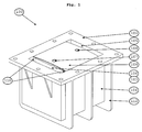
- FIG. 1 one embodiment of a fuel cell stack assembly (100) is shown.
- a housing (101) is shown with the open bottom interface end upwards. This end is provided with a flange (102) so the cell stack assembly can be connected to an interface counterpart of an SOFC system (not shown) in a simple, safe and gas tight manner.
- the fuel cell stack (103) is positioned in the housing, fixed in position by two flexible fixation mats (110) located inside the housing, one between one side of the housing and the adjacent side face of the fuel cell stack and the other located between the opposite side of the housing and its adjacent side face of the fuel cell stack. In this manner the fuel cell stack is squeezed between the two flexible fixation mats and thereby at least to some extent kept in position by the friction forces.
- the fuel cell stack is further fixed in its position in the housing by the flexible compression force mat (not shown) located inside the housing between the top end and the top face of the fuel cell stack.
- the compression force mat presses the fuel cell stack towards the opposite open bottom interface end of the housing where the flexible-interface-fixture (104) in form of a thin steel plate is reacting to the compression force with a counter-force is to some extent bend outwards because of its flexibility.
- the flexible-interface-fixture has a width corresponding to the inside width of the flange. As shown on Fig. 1 , the fuel cell stack is not in operation and therefore the flexibility of the flexible-interface-fixture plate is thus relative small as compared to the operation state where the temperature is considerably higher.
- the fuel cell stack of the embodiment shown in Fig. 1 is a combined external (air) and internal (fuel) manifolded stack.
- Oxidant gas such as ambient air is led to the side manifolded oxidant gas inlet of the fuel cell stack via the oxidant gas inlet (106) and is led away from the fuel cell stack via the oxidant gas outlet (105).
- the assembly is simple and robust in its construction since no actual external manifolds are necessary:
- the flexible fixation mats not only fix the fuel cell stack, but also ensures a gas tight seal between the housing side and the fuel cell stack, hence the external manifolds are constituted by the void between the side of the housing and the external manifold sides of the fuel cell stack.
- Fuel is led to and from the fuel cell stack via the fuel gas inlet (107) and the fuel gas outlet (108).
- all process gas connections are located on the same side of the assembly, the interface end of the housing.
- the interface as shown is a plane surface where the flange side and the external side of the flexible-interface-fixture are located in the same plane.
- the housing and the flange is stiffened by the stiffening and strengthening ribs (112) which make it possible to reduce the thickness of both the housing walls and the flange and thus the thermal mass and the material costs.
- Fig. 2 the same embodiment of the invention is now shown in a cut side view of the assembly, which enables the showing of the flexible compression force mat (211). It is visible that a fuel gas gasket (209) is located between the fuel cell stack (203) top face and the flexible-interface-fixture (204).
- the flexible-interface-fixture is here shown plane. As mentioned, it is more flexible and therefore more forces transferring when in operation, but still a slight, not shown, bend is possible also when not in operation.
- the fuel gasket is compressed by the compression force from the flexible compression force mat.
- flexible fixation mats (210) are located between two of the fuel cell stack side faces and two of the housing (201) sides to ensure fixation and gas sealing between the oxidation gas inlet side and the oxidation gas outlet side.
- the housing has an indent at the open bottom interface end for location of the flexible-interface-fixture.
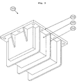
- Fig. 3 the external top end of the housing (301) is visible as well as two of the housing sides.
- the housing and the flange (302) for connection to a SOFC system interface counterpart is integrated, as is the stiffening and strengthening ribs (312).
- This embodiment can have cast steel housing.
- the current collectors which provides the electrical power output from the fuel cell.
- the terminals for the current collectors can be located on the top end of the housing. But other locations of the current terminals, such as the sides or the interface side of the assembly (to keep all connections on the same side) are also possible.
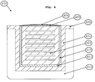
- Fig. 4 shows a cut side view of the assembly (400) as in Fig. 2 , but here the deflection of the flexible-interface-fixture (404) is shown.
- the flexible-interface-fixture is in this embodiment a steel plate. It is exposed to a force from the flexible compression force mat (411) via the cell stack (403) and the gasket (409), and as the thermal mass of the plate is kept low, the force bends the plate.
- the housing (401) has in this embodiment no indent for location of the plate. In stead the plate fits inside the housing and can be welded in a position where the surface of the flexible-interface-fixture is plane with the flange (402) as shown.
- stiffening and strengthening rib also serves to lower the thermal mass of the housing as compared to housing without ribs and thus the necessity for thicker walls and the ribs can serve as cooling ribs for the housing.
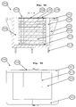
- Fig. 5A a side cut view of the cell stack assembly (500) in Fig. 5B is shown.
- the cut is made where the deflection of the flexible-interface-fixture (504) due to the force from the flexible compression force mat (511) is at its maximum and therefore the distance from the surface of the flange (502) to the surface of the flexible-interface-fixture is quite visible in the cut.
- a sealing gasket Between the flexible-interface-fixture and the cell stack (503) is a sealing gasket (509).
- the cell stack of this embodiment is a co-flow stack, which means that the oxidant gas flow direction is the same as the fuel gas flow direction, in this case from left to right in Fig 5A .
- the oxidant gas inlet (506) and the fuel gas inlet (507) is located in the left side of the assembly and the oxidant gas outlet (505) and the fuel gas outlet (508) is located in the right side of the assembly.
- the cell stack is a combined internal and external manifolded stack: the fuel gas side (anode) of the stack has internal manifolding and the oxidant gas side (cathode) of the stack has external manifolding.
- the external manifolds are simply the void between the cell stack and the housing (501).
- stiffening and strengthening ribs are round-going on two sides and the closed top end of the housing, whereas others are located only adjacent to the flange. They serve to stiffen and strengthen the housing but also to stiffen and strengthen the flange, which otherwise should have been made in larger dimensions. Hence the thermal mass is kept low.
- Fig. 6 the cell stack assembly (600) is shown in side cut view with the interface connected to an SOFC or SOEC system (650) to illustrate how the flexible-interface-fixture ((604) is plane and in the same plane as the flange (602) when the flange (602) is connected to the system flange (652) and at least a part of the force from the flexible compression force mat (611) is countered by the connection/packing force from the system flange.
- the force from the flexible compression force mat is transmitted to the flexible-interface-fixture via the cell stack (603) whereby it provides both a sealing force to the gaskets as well as a stack compression force.
- a system gasket (659) is shown, both gaskets providing sealing between the flanges and the gas connections.
- a large thermal mass is omitted since the counterpressure is provided by the connected system, which in any case needs to be rigid enough to provide a sealing force.
- the side cut on Fig. 6 also shows the two flexible fixation mats (610) between the cell stack and the housing (601) which serves to fix the stack in the correct position and provides gas seal between the oxidation gas inlet and outlet side of the cell stack.
- a stiffening and strengthening rib (612) as explained before is also shown.
- E is the elastic modulus for the chosen steel plate
- h is the thickness of the steel plate
- v is the Poisson's ratio
Landscapes
- Chemical & Material Sciences (AREA)
- Engineering & Computer Science (AREA)
- Electrochemistry (AREA)
- Chemical Kinetics & Catalysis (AREA)
- Sustainable Development (AREA)
- Sustainable Energy (AREA)
- Life Sciences & Earth Sciences (AREA)
- Manufacturing & Machinery (AREA)
- General Chemical & Material Sciences (AREA)
- Materials Engineering (AREA)
- Metallurgy (AREA)
- Organic Chemistry (AREA)
- Fuel Cell (AREA)
- Electrolytic Production Of Non-Metals, Compounds, Apparatuses Therefor (AREA)
Applications Claiming Priority (1)
| Application Number | Priority Date | Filing Date | Title |
|---|---|---|---|
| PCT/EP2011/005165 WO2013053374A1 (en) | 2011-10-14 | 2011-10-14 | Stack assembly |
Publications (2)
| Publication Number | Publication Date |
|---|---|
| EP2766947A1 EP2766947A1 (en) | 2014-08-20 |
| EP2766947B1 true EP2766947B1 (en) | 2016-06-15 |
Family
ID=44907786
Family Applications (1)
| Application Number | Title | Priority Date | Filing Date |
|---|---|---|---|
| EP11779092.3A Active EP2766947B1 (en) | 2011-10-14 | 2011-10-14 | Stack assembly |
Country Status (11)
| Country | Link |
|---|---|
| US (1) | US9865896B2 (enExample) |
| EP (1) | EP2766947B1 (enExample) |
| KR (1) | KR101899114B1 (enExample) |
| CN (1) | CN103875111B (enExample) |
| AU (1) | AU2011379051A1 (enExample) |
| CA (1) | CA2851718A1 (enExample) |
| DK (1) | DK2766947T3 (enExample) |
| EA (1) | EA201490791A1 (enExample) |
| ES (1) | ES2590341T3 (enExample) |
| IN (1) | IN2014CN02745A (enExample) |
| WO (1) | WO2013053374A1 (enExample) |
Families Citing this family (13)
| Publication number | Priority date | Publication date | Assignee | Title |
|---|---|---|---|---|
| ES2756340T3 (es) | 2016-12-14 | 2020-04-27 | Airbus Operations Gmbh | Método para adaptar e integrar una unidad de célula de combustible en un vehículo |
| GB2563848B (en) | 2017-06-26 | 2022-01-12 | Ceres Ip Co Ltd | Fuel cell stack assembly |
| JP2020534659A (ja) * | 2017-09-19 | 2020-11-26 | フイリツプス66カンパニー | 固体酸化物形燃料電池スタック設計 |
| KR102732487B1 (ko) * | 2018-12-06 | 2024-11-21 | 현대자동차주식회사 | 연료 전지 및 그의 제조 방법 |
| JP7196752B2 (ja) * | 2019-04-25 | 2022-12-27 | トヨタ自動車株式会社 | 電動車両 |
| KR102975015B1 (ko) * | 2020-07-31 | 2026-06-09 | 현대자동차주식회사 | 연료 전지 |
| ES3031400T3 (en) | 2021-07-08 | 2025-07-08 | Thyssenkrupp Nucera Ag & Co Kgaa | Electrolyzer with multi-cell elements |
| AT526002B1 (de) * | 2022-04-14 | 2023-12-15 | Avl List Gmbh | Dichtvorrichtung für zumindest einen Brennstoffzellenstapel |
| DE102022118660B4 (de) | 2022-07-26 | 2026-05-07 | Audi Aktiengesellschaft | Brennstoffzellenanordnung, Brennstoffzellenvorrichtung und Kraftfahrzeug |
| KR20250097816A (ko) * | 2022-10-27 | 2025-06-30 | 토프쉐 에이/에스 | 스택 모듈, 스택 모듈을 갖는 고체 산화물 전해조 및 고체 산화물 전해조의 스택 모듈 교환 방법 |
| AT527679B1 (de) * | 2023-12-07 | 2025-05-15 | Avl List Gmbh | Brennstoffzellenturm eines Brennstoffzellensystems, aufweisend ein Gehäuse |
| KR20250094277A (ko) * | 2023-12-18 | 2025-06-25 | 포스코홀딩스 주식회사 | 수전해 스택 조립체 및 핫박스 장치 |
| EP4621892A1 (en) | 2024-03-21 | 2025-09-24 | SolydEra SA | A stack assembly with a load applying mechanism |
Family Cites Families (24)
| Publication number | Priority date | Publication date | Assignee | Title |
|---|---|---|---|---|
| US4728585A (en) * | 1986-12-24 | 1988-03-01 | International Fuel Cells Corporation | Fuel cell stack with combination end-pressure plates |
| US5169730A (en) * | 1990-07-25 | 1992-12-08 | Westinghouse Electric Corp. | Electrochemical cell apparatus having an exterior fuel mixer nozzle |
| US7189468B2 (en) * | 2001-03-16 | 2007-03-13 | Creare Inc. | Lightweight direct methanol fuel cell |
| US6692859B2 (en) | 2001-05-09 | 2004-02-17 | Delphi Technologies, Inc. | Fuel and air supply base manifold for modular solid oxide fuel cells |
| DE10124853A1 (de) | 2001-05-22 | 2002-11-28 | Bayerische Motoren Werke Ag | Brennstoffzelle |
| JP4228597B2 (ja) * | 2001-06-08 | 2009-02-25 | トヨタ自動車株式会社 | 燃料電池 |
| US7294424B2 (en) | 2002-06-24 | 2007-11-13 | Delphi Technologies, Inc. | Solid-oxide fuel cell assembly having simplified arrangement of current collectors |
| JP2004134181A (ja) | 2002-10-09 | 2004-04-30 | Nissan Motor Co Ltd | 燃料電池容器構造 |
| DE10250345A1 (de) | 2002-10-29 | 2004-05-13 | Volkswagen Ag | Brennstoffzellenanordnung |
| JP4417204B2 (ja) * | 2004-08-27 | 2010-02-17 | 本田技研工業株式会社 | 燃料電池スタック |
| JP4795016B2 (ja) * | 2005-09-06 | 2011-10-19 | 本田技研工業株式会社 | 燃料電池スタック |
| ES2421632T3 (es) * | 2005-10-25 | 2013-09-04 | Bic Soc | Sistemas de alimentación de combustible que tienen resistencia operativa |
| DE102005051583A1 (de) * | 2005-10-27 | 2007-05-03 | Airbus Deutschland Gmbh | Brennstoffzellensystem für die Versorgung von Luftfahrzeugen |
| JP2007273303A (ja) * | 2006-03-31 | 2007-10-18 | Mitsubishi Materials Corp | 固体酸化物形燃料電池 |
| US7879507B2 (en) * | 2006-04-10 | 2011-02-01 | Protonex Technology Corporation | Insert-molded, externally manifolded, one-shot sealed membrane based electrochemical cell stacks |
| DE102006060809A1 (de) | 2006-12-21 | 2008-06-26 | Enerday Gmbh | Isolier- und Verspannvorrichtung für eine Hochtemperatur-Brennstoffzellensystemkomponente |
| US7858259B2 (en) * | 2007-01-26 | 2010-12-28 | Topsoe Fuel Cell A/S | Fuel cell stack clamping structure and solid oxide fuel cell stack |
| KR20080076236A (ko) | 2007-02-15 | 2008-08-20 | 주식회사 하이닉스반도체 | 반도체 소자의 금속 배선 형성 방법 |
| GB0703762D0 (en) * | 2007-02-27 | 2007-04-04 | Ceres Ip Co Ltd | Improved hot box |
| WO2008104760A1 (en) | 2007-02-27 | 2008-09-04 | Ceres Intellectual Property Company Limited | Fuel cell stack flow hood |
| JP5405858B2 (ja) * | 2008-04-14 | 2014-02-05 | 日産自動車株式会社 | 組電池、組電池の製造方法および組電池を搭載した車両 |
| ES2480272T3 (es) * | 2009-03-13 | 2014-07-25 | Topsoe Fuel Cell A/S | Carcasa de compresión para una pila de células de combustible y método para la fabricación de una carcasa de compresión para una pila de células de combustible |
| WO2010108530A1 (en) * | 2009-03-26 | 2010-09-30 | Topsoe Fuel Cell A/S | Compression arrangement for fuel or electrolysis cells in a fuel cell stack or an electrolysis cell stack |
| US20110244355A1 (en) * | 2010-04-01 | 2011-10-06 | Gm Global Technology Operations, Inc. | Fuel cell stack compression enclosure apparatus |
-
2011
- 2011-10-14 DK DK11779092.3T patent/DK2766947T3/en active
- 2011-10-14 EA EA201490791A patent/EA201490791A1/ru unknown
- 2011-10-14 AU AU2011379051A patent/AU2011379051A1/en not_active Abandoned
- 2011-10-14 KR KR1020147012828A patent/KR101899114B1/ko active Active
- 2011-10-14 ES ES11779092.3T patent/ES2590341T3/es active Active
- 2011-10-14 CA CA2851718A patent/CA2851718A1/en not_active Abandoned
- 2011-10-14 CN CN201180074152.0A patent/CN103875111B/zh active Active
- 2011-10-14 WO PCT/EP2011/005165 patent/WO2013053374A1/en not_active Ceased
- 2011-10-14 EP EP11779092.3A patent/EP2766947B1/en active Active
- 2011-10-14 US US14/351,435 patent/US9865896B2/en active Active
- 2011-10-14 IN IN2745CHN2014 patent/IN2014CN02745A/en unknown
Also Published As
| Publication number | Publication date |
|---|---|
| CA2851718A1 (en) | 2013-04-18 |
| WO2013053374A1 (en) | 2013-04-18 |
| US9865896B2 (en) | 2018-01-09 |
| KR20140084173A (ko) | 2014-07-04 |
| IN2014CN02745A (enExample) | 2015-07-03 |
| US20140234744A1 (en) | 2014-08-21 |
| HK1199150A1 (zh) | 2015-06-19 |
| EP2766947A1 (en) | 2014-08-20 |
| DK2766947T3 (en) | 2016-09-12 |
| CN103875111B (zh) | 2016-10-19 |
| KR101899114B1 (ko) | 2018-09-17 |
| ES2590341T3 (es) | 2016-11-21 |
| AU2011379051A1 (en) | 2014-05-01 |
| CN103875111A (zh) | 2014-06-18 |
| EA201490791A1 (ru) | 2014-09-30 |
Similar Documents
| Publication | Publication Date | Title |
|---|---|---|
| US9865896B2 (en) | Stack assembly comprising flexible compression force mat | |
| US9034534B2 (en) | Compression casing for a fuel cell stack and a method for manufacturing a compression casing for a fuel cell stack | |
| CN102770982B (zh) | 电池组 | |
| EP3788670A1 (en) | Fuel cell stack | |
| US20100092839A1 (en) | Fuel cell system | |
| US20230307744A1 (en) | Electric Battery Assembly | |
| WO2025208801A9 (zh) | 电池及用电装置 | |
| CN107408709A (zh) | 模块化燃料电池系统 | |
| US20080138670A1 (en) | Compact fuel cell stack with multiple plate arrangement | |
| WO2025077995A1 (en) | Electrochemical cell assembly | |
| US20080138667A1 (en) | Compact fuel cell stack with fastening member | |
| HK1199150B (en) | Stack assembly | |
| CN117558958B (zh) | 电池堆结构 | |
| US10693152B2 (en) | Fuel cell stack with thin endplate with integrated gas distribution tubes | |
| CN222620041U (zh) | 一种泄爆转接管、大容量电池组件以及电池包 | |
| JP5136471B2 (ja) | 燃料電池 | |
| JPH0821401B2 (ja) | 溶融炭酸塩燃料電池 | |
| WO2026040528A1 (zh) | 底板、底板组件、电池包箱体及电池包 | |
| HK1168471B (en) | Compression casing for a fuel cell stack and a method for manufacturing a compression casing for a fuel cell stack | |
| CN121058123A (zh) | 模块盖、电池组和车辆 | |
| JPH07192750A (ja) | 常圧型燃料電池 |
Legal Events
| Date | Code | Title | Description |
|---|---|---|---|
| PUAI | Public reference made under article 153(3) epc to a published international application that has entered the european phase |
Free format text: ORIGINAL CODE: 0009012 |
|
| 17P | Request for examination filed |
Effective date: 20140321 |
|
| AK | Designated contracting states |
Kind code of ref document: A1 Designated state(s): AL AT BE BG CH CY CZ DE DK EE ES FI FR GB GR HR HU IE IS IT LI LT LU LV MC MK MT NL NO PL PT RO RS SE SI SK SM TR |
|
| DAX | Request for extension of the european patent (deleted) | ||
| 17Q | First examination report despatched |
Effective date: 20150402 |
|
| RAP1 | Party data changed (applicant data changed or rights of an application transferred) |
Owner name: HALDOR TOPSOEE A/S |
|
| RIC1 | Information provided on ipc code assigned before grant |
Ipc: H01M 8/24 20060101AFI20151202BHEP Ipc: H01M 8/12 20060101ALN20151202BHEP |
|
| GRAP | Despatch of communication of intention to grant a patent |
Free format text: ORIGINAL CODE: EPIDOSNIGR1 |
|
| INTG | Intention to grant announced |
Effective date: 20160108 |
|
| RIN1 | Information on inventor provided before grant (corrected) |
Inventor name: ERIKSTRUP, NIELS Inventor name: BREINER, JACOB Inventor name: NIELSEN, MARTIN, REFSLUND |
|
| GRAS | Grant fee paid |
Free format text: ORIGINAL CODE: EPIDOSNIGR3 |
|
| GRAA | (expected) grant |
Free format text: ORIGINAL CODE: 0009210 |
|
| AK | Designated contracting states |
Kind code of ref document: B1 Designated state(s): AL AT BE BG CH CY CZ DE DK EE ES FI FR GB GR HR HU IE IS IT LI LT LU LV MC MK MT NL NO PL PT RO RS SE SI SK SM TR |
|
| REG | Reference to a national code |
Ref country code: CH Ref legal event code: EP Ref country code: GB Ref legal event code: FG4D |
|
| REG | Reference to a national code |
Ref country code: IE Ref legal event code: FG4D |
|
| REG | Reference to a national code |
Ref country code: AT Ref legal event code: REF Ref document number: 806900 Country of ref document: AT Kind code of ref document: T Effective date: 20160715 |
|
| REG | Reference to a national code |
Ref country code: DE Ref legal event code: R096 Ref document number: 602011027467 Country of ref document: DE |
|
| REG | Reference to a national code |
Ref country code: DK Ref legal event code: T3 Effective date: 20160909 |
|
| REG | Reference to a national code |
Ref country code: LT Ref legal event code: MG4D |
|
| REG | Reference to a national code |
Ref country code: NL Ref legal event code: MP Effective date: 20160615 |
|
| PG25 | Lapsed in a contracting state [announced via postgrant information from national office to epo] |
Ref country code: NO Free format text: LAPSE BECAUSE OF FAILURE TO SUBMIT A TRANSLATION OF THE DESCRIPTION OR TO PAY THE FEE WITHIN THE PRESCRIBED TIME-LIMIT Effective date: 20160915 Ref country code: LT Free format text: LAPSE BECAUSE OF FAILURE TO SUBMIT A TRANSLATION OF THE DESCRIPTION OR TO PAY THE FEE WITHIN THE PRESCRIBED TIME-LIMIT Effective date: 20160615 Ref country code: FI Free format text: LAPSE BECAUSE OF FAILURE TO SUBMIT A TRANSLATION OF THE DESCRIPTION OR TO PAY THE FEE WITHIN THE PRESCRIBED TIME-LIMIT Effective date: 20160615 |
|
| REG | Reference to a national code |
Ref country code: AT Ref legal event code: MK05 Ref document number: 806900 Country of ref document: AT Kind code of ref document: T Effective date: 20160615 |
|
| REG | Reference to a national code |
Ref country code: ES Ref legal event code: FG2A Ref document number: 2590341 Country of ref document: ES Kind code of ref document: T3 Effective date: 20161121 |
|
| PG25 | Lapsed in a contracting state [announced via postgrant information from national office to epo] |
Ref country code: RS Free format text: LAPSE BECAUSE OF FAILURE TO SUBMIT A TRANSLATION OF THE DESCRIPTION OR TO PAY THE FEE WITHIN THE PRESCRIBED TIME-LIMIT Effective date: 20160615 Ref country code: LV Free format text: LAPSE BECAUSE OF FAILURE TO SUBMIT A TRANSLATION OF THE DESCRIPTION OR TO PAY THE FEE WITHIN THE PRESCRIBED TIME-LIMIT Effective date: 20160615 Ref country code: NL Free format text: LAPSE BECAUSE OF FAILURE TO SUBMIT A TRANSLATION OF THE DESCRIPTION OR TO PAY THE FEE WITHIN THE PRESCRIBED TIME-LIMIT Effective date: 20160615 Ref country code: SE Free format text: LAPSE BECAUSE OF FAILURE TO SUBMIT A TRANSLATION OF THE DESCRIPTION OR TO PAY THE FEE WITHIN THE PRESCRIBED TIME-LIMIT Effective date: 20160615 Ref country code: GR Free format text: LAPSE BECAUSE OF FAILURE TO SUBMIT A TRANSLATION OF THE DESCRIPTION OR TO PAY THE FEE WITHIN THE PRESCRIBED TIME-LIMIT Effective date: 20160916 Ref country code: HR Free format text: LAPSE BECAUSE OF FAILURE TO SUBMIT A TRANSLATION OF THE DESCRIPTION OR TO PAY THE FEE WITHIN THE PRESCRIBED TIME-LIMIT Effective date: 20160615 |
|
| PG25 | Lapsed in a contracting state [announced via postgrant information from national office to epo] |
Ref country code: IT Free format text: LAPSE BECAUSE OF FAILURE TO SUBMIT A TRANSLATION OF THE DESCRIPTION OR TO PAY THE FEE WITHIN THE PRESCRIBED TIME-LIMIT Effective date: 20160615 Ref country code: IS Free format text: LAPSE BECAUSE OF FAILURE TO SUBMIT A TRANSLATION OF THE DESCRIPTION OR TO PAY THE FEE WITHIN THE PRESCRIBED TIME-LIMIT Effective date: 20161015 Ref country code: SK Free format text: LAPSE BECAUSE OF FAILURE TO SUBMIT A TRANSLATION OF THE DESCRIPTION OR TO PAY THE FEE WITHIN THE PRESCRIBED TIME-LIMIT Effective date: 20160615 Ref country code: RO Free format text: LAPSE BECAUSE OF FAILURE TO SUBMIT A TRANSLATION OF THE DESCRIPTION OR TO PAY THE FEE WITHIN THE PRESCRIBED TIME-LIMIT Effective date: 20160615 Ref country code: EE Free format text: LAPSE BECAUSE OF FAILURE TO SUBMIT A TRANSLATION OF THE DESCRIPTION OR TO PAY THE FEE WITHIN THE PRESCRIBED TIME-LIMIT Effective date: 20160615 Ref country code: CZ Free format text: LAPSE BECAUSE OF FAILURE TO SUBMIT A TRANSLATION OF THE DESCRIPTION OR TO PAY THE FEE WITHIN THE PRESCRIBED TIME-LIMIT Effective date: 20160615 |
|
| PG25 | Lapsed in a contracting state [announced via postgrant information from national office to epo] |
Ref country code: AT Free format text: LAPSE BECAUSE OF FAILURE TO SUBMIT A TRANSLATION OF THE DESCRIPTION OR TO PAY THE FEE WITHIN THE PRESCRIBED TIME-LIMIT Effective date: 20160615 Ref country code: PT Free format text: LAPSE BECAUSE OF FAILURE TO SUBMIT A TRANSLATION OF THE DESCRIPTION OR TO PAY THE FEE WITHIN THE PRESCRIBED TIME-LIMIT Effective date: 20161017 Ref country code: PL Free format text: LAPSE BECAUSE OF FAILURE TO SUBMIT A TRANSLATION OF THE DESCRIPTION OR TO PAY THE FEE WITHIN THE PRESCRIBED TIME-LIMIT Effective date: 20160615 Ref country code: SM Free format text: LAPSE BECAUSE OF FAILURE TO SUBMIT A TRANSLATION OF THE DESCRIPTION OR TO PAY THE FEE WITHIN THE PRESCRIBED TIME-LIMIT Effective date: 20160615 Ref country code: BE Free format text: LAPSE BECAUSE OF NON-PAYMENT OF DUE FEES Effective date: 20160615 |
|
| REG | Reference to a national code |
Ref country code: DE Ref legal event code: R097 Ref document number: 602011027467 Country of ref document: DE |
|
| PLBE | No opposition filed within time limit |
Free format text: ORIGINAL CODE: 0009261 |
|
| STAA | Information on the status of an ep patent application or granted ep patent |
Free format text: STATUS: NO OPPOSITION FILED WITHIN TIME LIMIT |
|
| 26N | No opposition filed |
Effective date: 20170316 |
|
| REG | Reference to a national code |
Ref country code: CH Ref legal event code: PL |
|
| REG | Reference to a national code |
Ref country code: IE Ref legal event code: MM4A |
|
| REG | Reference to a national code |
Ref country code: FR Ref legal event code: ST Effective date: 20170630 |
|
| PG25 | Lapsed in a contracting state [announced via postgrant information from national office to epo] |
Ref country code: LI Free format text: LAPSE BECAUSE OF NON-PAYMENT OF DUE FEES Effective date: 20161031 Ref country code: CH Free format text: LAPSE BECAUSE OF NON-PAYMENT OF DUE FEES Effective date: 20161031 Ref country code: FR Free format text: LAPSE BECAUSE OF NON-PAYMENT OF DUE FEES Effective date: 20161102 |
|
| PG25 | Lapsed in a contracting state [announced via postgrant information from national office to epo] |
Ref country code: SI Free format text: LAPSE BECAUSE OF FAILURE TO SUBMIT A TRANSLATION OF THE DESCRIPTION OR TO PAY THE FEE WITHIN THE PRESCRIBED TIME-LIMIT Effective date: 20160615 Ref country code: LU Free format text: LAPSE BECAUSE OF NON-PAYMENT OF DUE FEES Effective date: 20161014 |
|
| PG25 | Lapsed in a contracting state [announced via postgrant information from national office to epo] |
Ref country code: IE Free format text: LAPSE BECAUSE OF NON-PAYMENT OF DUE FEES Effective date: 20161014 |
|
| PG25 | Lapsed in a contracting state [announced via postgrant information from national office to epo] |
Ref country code: HU Free format text: LAPSE BECAUSE OF FAILURE TO SUBMIT A TRANSLATION OF THE DESCRIPTION OR TO PAY THE FEE WITHIN THE PRESCRIBED TIME-LIMIT; INVALID AB INITIO Effective date: 20111014 |
|
| PG25 | Lapsed in a contracting state [announced via postgrant information from national office to epo] |
Ref country code: MK Free format text: LAPSE BECAUSE OF FAILURE TO SUBMIT A TRANSLATION OF THE DESCRIPTION OR TO PAY THE FEE WITHIN THE PRESCRIBED TIME-LIMIT Effective date: 20160615 Ref country code: MC Free format text: LAPSE BECAUSE OF FAILURE TO SUBMIT A TRANSLATION OF THE DESCRIPTION OR TO PAY THE FEE WITHIN THE PRESCRIBED TIME-LIMIT Effective date: 20160615 Ref country code: MT Free format text: LAPSE BECAUSE OF NON-PAYMENT OF DUE FEES Effective date: 20161031 Ref country code: CY Free format text: LAPSE BECAUSE OF FAILURE TO SUBMIT A TRANSLATION OF THE DESCRIPTION OR TO PAY THE FEE WITHIN THE PRESCRIBED TIME-LIMIT Effective date: 20160615 |
|
| PG25 | Lapsed in a contracting state [announced via postgrant information from national office to epo] |
Ref country code: BG Free format text: LAPSE BECAUSE OF FAILURE TO SUBMIT A TRANSLATION OF THE DESCRIPTION OR TO PAY THE FEE WITHIN THE PRESCRIBED TIME-LIMIT Effective date: 20160615 |
|
| PG25 | Lapsed in a contracting state [announced via postgrant information from national office to epo] |
Ref country code: AL Free format text: LAPSE BECAUSE OF FAILURE TO SUBMIT A TRANSLATION OF THE DESCRIPTION OR TO PAY THE FEE WITHIN THE PRESCRIBED TIME-LIMIT Effective date: 20160615 Ref country code: TR Free format text: LAPSE BECAUSE OF FAILURE TO SUBMIT A TRANSLATION OF THE DESCRIPTION OR TO PAY THE FEE WITHIN THE PRESCRIBED TIME-LIMIT Effective date: 20160615 |
|
| P01 | Opt-out of the competence of the unified patent court (upc) registered |
Effective date: 20230602 |
|
| PGFP | Annual fee paid to national office [announced via postgrant information from national office to epo] |
Ref country code: DE Payment date: 20251028 Year of fee payment: 15 |
|
| PGFP | Annual fee paid to national office [announced via postgrant information from national office to epo] |
Ref country code: GB Payment date: 20251023 Year of fee payment: 15 |
|
| PGFP | Annual fee paid to national office [announced via postgrant information from national office to epo] |
Ref country code: DK Payment date: 20251024 Year of fee payment: 15 |
|
| PGFP | Annual fee paid to national office [announced via postgrant information from national office to epo] |
Ref country code: ES Payment date: 20251118 Year of fee payment: 15 |