EP2765097A1 - Assembly for collecting and disposing of household refuse - Google Patents
Assembly for collecting and disposing of household refuse Download PDFInfo
- Publication number
- EP2765097A1 EP2765097A1 EP14154273.8A EP14154273A EP2765097A1 EP 2765097 A1 EP2765097 A1 EP 2765097A1 EP 14154273 A EP14154273 A EP 14154273A EP 2765097 A1 EP2765097 A1 EP 2765097A1
- Authority
- EP
- European Patent Office
- Prior art keywords
- tank
- bucket
- vehicle
- vessel
- tilting
- Prior art date
- Legal status (The legal status is an assumption and is not a legal conclusion. Google has not performed a legal analysis and makes no representation as to the accuracy of the status listed.)
- Granted
Links
Images


Classifications
-
- B—PERFORMING OPERATIONS; TRANSPORTING
- B65—CONVEYING; PACKING; STORING; HANDLING THIN OR FILAMENTARY MATERIAL
- B65F—GATHERING OR REMOVAL OF DOMESTIC OR LIKE REFUSE
- B65F3/00—Vehicles particularly adapted for collecting refuse
-
- B—PERFORMING OPERATIONS; TRANSPORTING
- B65—CONVEYING; PACKING; STORING; HANDLING THIN OR FILAMENTARY MATERIAL
- B65F—GATHERING OR REMOVAL OF DOMESTIC OR LIKE REFUSE
- B65F3/00—Vehicles particularly adapted for collecting refuse
- B65F3/02—Vehicles particularly adapted for collecting refuse with means for discharging refuse receptacles thereinto
- B65F3/08—Platform elevators or hoists with guides or runways for raising or tipping receptacles
-
- B—PERFORMING OPERATIONS; TRANSPORTING
- B65—CONVEYING; PACKING; STORING; HANDLING THIN OR FILAMENTARY MATERIAL
- B65F—GATHERING OR REMOVAL OF DOMESTIC OR LIKE REFUSE
- B65F3/00—Vehicles particularly adapted for collecting refuse
- B65F2003/006—Constructional features relating to the tank of the refuse vehicle
- B65F2003/008—Constructional features relating to the tank of the refuse vehicle interchangeable
Definitions
- the present invention relates to the field of land transport of materials, including waste.
- the invention relates to a collection and removal of waste, including household waste, in urban or peri-urban areas.
- One of the problems at the moment, in the field of collection and disposal of waste, is to be able easily reach the hearts of city to collect the waste and to be able to evacuate them on the outskirts of the city towards sites such as landfills, reprocessing centers, or selective sorting centers.
- the invention particularly aims to solve the disadvantages of the prior art.
- an object of the invention is to provide a technique for limiting interference with urban traffic that is dense in the heart of the city (cars, trucks, two-wheeled vehicles, pedestrians, ).
- Another object of the invention is to provide a technique for limiting the carbon impact related to these collections and waste movements, and to limit energy consumption while providing a relatively "clean" solution.
- Yet another object of the invention is to provide a technique for optimizing the circulation of the waste stream to be collected and discharged.
- an object of the invention is to provide a technique that is inexpensive and simple to implement.
- the invention proposes a new and inventive approach to limit the interference between the collection assembly and the urban traffic. Indeed, the fact of implementing tanks, in which waste is collected, and then to transfer these tanks in skips that are located outside the city, reduce the clutter of the means that penetrate the city. interior of the city and thus to limit or even eliminate the gene caused.
- the bucket comprises at least one passage, provided on at least one of its walls, to pass the tank into the bucket via the transfer means.
- the support and the second tilting means of the tank are mounted respectively on the first vehicle, and in part on the first tilting means and the bucket.
- the support and the second tilting means of the vessel are mounted respectively on the first vehicle, and in part on the first vehicle and the vessel.
- the first and second tilting means of the vessel operate in a first and a second direction and intervene at the location of two separate walls.
- the means used and the activity are distributed at the level of the walls in order to optimize the forces required for each of the walls.
- the assembly comprises means for moving the vessel, to move the upright vessel, in the bucket, between the support of the vessel and a part of the first tilting means, carried by the bucket.
- the energy consumption of the assembly is limited by implementing displacement means that make it possible to avoid exerting forces on the tank to place it directly on the tipping means of the body.
- the means for moving the tank can be mounted on the first vehicle and the tank.
- the activity is distributed at the level of each of the "entities" of the group while facilitating cooperation between these entities.
- the tank support is mounted to move on the first vehicle between a first rearward position for tilting the vessel and a second advanced position for loading waste into the vessel. via a loading hopper equipping the first vehicle.
- the means implemented in the invention are optimized by the use of a single support for several phases of the collection and disposal of waste, while simplifying the transfer of the vessel to the by the realization of this transfer by means of simple mechanical movements.
- the assembly comprises a second vehicle, heavier and larger than the first vehicle and on which is removably mounted the bucket, which then contains several full tanks, to move said bucket to the unloading area .
- the transfer of the tank from the first vehicle into the bucket comprises a displacement of the tank erected in the bucket, by pushing means carried by the first vehicle, until the tank is placed in position to be reversibly locked to an upstanding wall of the bucket, in order to tilt the vessel over this wall during its emptying.
- the assembly comprises a first vehicle 3 on which is mounted a tank 1 for collecting waste, a priori household waste.
- the first vehicle 3 otherwise called collection vehicle, is a relatively light and compact vehicle to limit the inconvenience caused by the circulation of the first vehicle 3 in the heart of a vehicle. city.
- this collection vehicle 3 is equipped with a clean energy and low energy motor, such as an electric motor, hybrid or compressed air, so as to limit the environmental impact and energy cost.
- the propulsion engine 30 of the vehicle 3 be clean energy, and therefore not internal combustion.
- the first vehicle 3 will also preferably comprise a hopper 31 for loading refuse and means 32 ( figure 3 ) of compression of this waste which compresses the waste conveyed by the hopper 31 before bringing them to the tank 1.
- a lateral passage 310 connects the hopper and the inside of the tank, opening side 10.
- This embodiment illustrates a first vehicle adapted so that on it can be mounted only one tank, which is preferred.
- This waste storage tank 1 has, in this embodiment, a cylindrical profile. It is mounted removably vis-à-vis the collection vehicle 3 via a support 41. It comprises an opening 10 for receiving waste that can be arrived by the hopper 31. This opening can also serve, in this embodiment, to empty the tank 1.
- the tank has several openings, including one to fill it, one to empty it, this second opening 110 can be placed on the side of the tank (see figure 11 ) or the opposite.
- the tank 1 will be mounted horizontally on the support or cradle 41, that is to say in a direction where its longest side is substantially parallel to the ground and to the longitudinal axis 3a of the vehicle 3 and of its support 41. Its opening 10 is directed towards the front (AV) of the vehicle, its fixed bottom 100 to the rear (AR), where the tank is loaded and unloaded, here longitudinally.
- the assembly also comprises a bucket 2.
- This bucket 2 otherwise called container, comprises (here four) erected walls 21, 22, 23, 24 (the so-called front wall 21 not being represented on the figures 1 , 2 , for the sake of clarity) and a horizontal bottom 25, the walls and the bottom defining the volume of the bucket. In this example, the volume of the bucket is about 40 m 3 . It comprises several (here three) compartments each receiving a tank 1.
- the bucket 2 further comprises passages 26 formed on the front wall 21, for transferring the tanks from the first vehicle into the bucket 2 via transfer means 4. These passages 26 can be closed, in a preferred embodiment, by doors 260 (see figure 9 ), or hatches, which are selectively closed to open and close access to the passage. These doors may for example be pivotally mounted relative to the bottom 25 or with respect to one of the side walls.
- this bucket will be placed outside a major urban concentration area so as not to hinder traffic in this area.
- this bucket 2 can place such a bucket 2 on the outskirts of the city center, the collection vehicles 3 conveying the full tanks to or from this bucket 2, by round trips.
- the collection and disposal of waste also comprises first transfer means 4 of the vessel 1 on the bucket 2, locking means 5 to reversibly lock the vessel 1 to the bucket 2, and first means 6 tilting of the vessel 1, then locked to the bucket 2, to empty the vessel 1 outside the bucket 2.
- the locking means 5 are formed on a wall of the bucket and on / each tank.
- each first vehicle 3 be provided with a power source, such as the engine 30 or an auxiliary source 300, which supplies power to the first means 4 for transferring the tank, exclusively.
- a power source such as the engine 30 or an auxiliary source 300, which supplies power to the first means 4 for transferring the tank, exclusively.
- These transfer means 4 make it possible to transfer the tank 1 transported by the first vehicle 3 onto the body 2. They comprise, in this example, the support 41 which is mounted on the first vehicle 1, and the second means 42 of tilting of the tank 1 which makes it possible to tilt the tank 1 with respect to the support 41 between the first vehicle 3 and the skip 2.
- the support 41 of the tank 1 is mounted to move on the first vehicle 3 between a rearward rearward position (AR), for the tilting of the tank 1, and a second advanced position for the loading of waste in the tank 1 via the hopper 31.
- the rear position (AR) is preferably reclosed cantilever vis-à-vis the vehicle , for the transfer of the tank to the bucket.
- the second tilting means 42 are mounted, in this embodiment, partly on the tank 1, the bucket 2, the first vehicle 3, and the first tilting means 6.
- the second means tilting 42 are in the form of guide pins 421 (mounted on the first tilting means 6) flowing in guide rails 422 (mounted on the body 2), and a cable (mounted on the first vehicle 3, not shown in these two figures) connected to a fastener (mounted on the tank 1, not shown in these two figures).
- these transfer means 4 make the tank 1 pass from a horizontal position, when it is on the support 41, to a position erected in the body, by means of the second tilting means 42.
- the locking means 5 allow to lock the tank to the bucket reversibly.
- the locking means are in the form of "hooks" vertical 51 formed along an upstanding wall 23 of the bucket 2 and cooperating with a retaining bar 52 formed on the first tilting means 6.
- the second means 42 of tilting are mounted in part on the first tilting means and on the bucket 2, to tilt the tank, from the retracted position cantilevered on the support 41.
- the first switching means 6, otherwise called berces, are individual.
- each tank 1 comes to cooperate with different tilting means 6.
- the assembly comprises three "first tilting means 6", that is to say three bays.
- the first vehicle 3 Prior to the transfer of the tank 1 full of waste from the first vehicle 3 to the bucket 2, the first vehicle 3 approaches and stops near the bucket 2. It is placed vis-à-vis a passage 26, and therefore a cradle 6. In this phase, the support 41 supports the tank 1 in the collection vehicle 3.
- the full tank 1 is transferred by retreating it, in a first step, cantilevered with respect to the support 41.
- the tank 1 is translated by a mechanical action that backs lateral arms connected to the support 41, so the support, which is then in the rearward position.
- the figure 3 illustrates this first time.
- the first tilting means 6 cooperate with the tank, in this example by means of three bars 611 housed in hollow ears 11 formed on the tank 1.
- the side bars 611a, 611b slide horizontally in rails 422 fixed on the bucket.
- the vessel 1 is tilted, always preferably cantilevered with respect to the support 41, by gravity in a first direction ⁇ which is, in this example and this angle of view, counterclockwise, so as to to straighten it.
- the tilting of the tank and the recovery of the tank are also performed by the second tilting means 42 which guide the descent / fall by gravity of the tank 1 and which then allow to recover, when it came into contact or near the bottom 25 of the bucket 2.
- the guiding pins 421 circulate in the rails 422, divided into a horizontal portion and then a vertical portion, so as to guide the descent by gravity of the tank 1, then the cable 423 (operated by the power source 30 or 300 ) pulls the tank 1 at its base through the fastener 424 to straighten it.
- the tank 1 is then erect, vertically.
- This straightening through the cable 423 can be achieved by a return of the support 41 in its advanced position, the cable being fixed to a traction means connected in this example to the support 41.
- the cable pulls the base of the tank 1 in its pivoting direction and the rectifier, thus placing the vessel 1 on moving means 8 (here wheels under its fixed bottom, full 100).
- this cable otherwise called rigid rod, is mounted detachable vis-à-vis the tank.
- moving means mounted on the vessel 1 and also on the first vehicle 3, in the form for example of an arm.
- the tank 1 is raised in the bucket 2 by the displacement means 8 associated with a mechanical action from the collection vehicle 3 (in this case a recoil of the first vehicle and more particularly of the support 41 mounted on the first vehicle 3 ), until the tank 1 in position to be reversibly locked to the locking means 5 carried by the wall 23 "dorsal".
- the vessel 1 is in position to be tilted and emptied, in a second direction ⁇ , out of the bucket.
- the second direction is, here and preferably, also the counterclockwise direction, the first sense ⁇ and second sense ⁇ being then identical.
- the first vehicle can be placed at a distance from the bucket, this distance being relatively small, so as to "participate” in the forces exerted on the bucket to move it back into the first tilting means and / or the locking means.
- the first vehicle can be placed at a distance of less than two meters from the bucket, so as not to be too far for the removal of the tank in the bucket.
- the assembly comprises a storage tank 1 'which has a parallelepiped profile and is mounted on a support 41' of a first collection vehicle 3 '.
- the set includes also a bucket 2 'which has three erect walls 21', 22 ', 23', and a passage or a front opening (e) 26 'provided (e) to facilitate the transfer of the tanks 1' from the first collection vehicle 3 'to the bucket 2'.
- An erected face of the bucket 2 ' is thus open. At its summit the bucket is also open here.
- a hopper 31 of waste loading, or means 32' of compression of this waste through the side passage 310 '.
- the one concerned here also comprises transfer means 4 'in the form of the support 41' mounted mobile in translation and in rotation on the first vehicle 3 ', and second tilting means 42 '.
- the second tilting means 42 ' are partly mounted on the tank 1' (via guiding pins 421 '), on the bucket 2' (guide rails 422 'in which the pieces may circulate). guide 421 ') and on the support 41' (retaining hook 423 ').
- this assembly also comprises means 5 'reversibly locking the vessel 1' in the bucket 2 ', these locking means being formed in part on the bucket 2' and on the tank 1 '.
- the assembly comprises first means (not shown in these figures) of tilting of the tank 1 'which are placed partly on the bucket 2' and partly at a distance from this bucket.
- the bucket is designed to receive several 1 'full tanks; preferably by superposition of these tanks.
- we tilt the front portion of the support 41 ' that is to say the part closest to the front of the first vehicle 3', in a first direction ⁇ 'directed rearwardly to slide the tank full by gravity.
- This descent of the tank is controlled by the second tilting means 42 ', which can also serve as a brake to slow down the fall and avoid altering the tank or the support.
- the second tilting means 42 ' and more particularly the means provided on the tank and on the bucket 2', guide the tank to its location in the bucket.
- the upper tank ( figure 8 ) it is transferred from the first vehicle 3 'to the bucket 2' by a vertical translation upwardly of the support 41 ', or by a lifting plate 410', so as to place the tank vis-à-vis its location in the bucket 2 '. Subsequently, the upper tank is pushed by a portion of the second tilting means 42 ', in this case the hook 423' to place it at the bottom of the bucket and to lock reversibly to the bucket 2 ' through the locking means 5 '. It should be noted that this thrust phase of the tank in the bucket can be guided by guide pins 421 'of the vessel which slide in second guide rails of the dumpster.
- the means 420 ' may be cylinders.
- the assembly comprises a second vehicle 9, heavier and bulkier than the first vehicle 3.
- This second vehicle makes it possible to move the bucket, then containing one or more full tanks, to an unloading zone 50 ( figure 10 ). Because this second vehicle does not circulate or only in urban areas with a high concentration of vehicles and pedestrians, its relatively larger size than that of the first vehicle is not embarrassing.
- the latter comprises third tilting means 91 in the form, in this example, of a crane formed on the rear part of the second vehicle and which comes to pull the bucket, by via a hook 911 of the crane connected to an ear 912 of the bucket.
- the bucket can be, for example, reversibly attached to the second vehicle by second locking means 500 ( figure 10 ), this allows to move to the unloading area without risk of overturning thereof.
- these first means 6 of tilting of the tank will be favorably mounted mobile in rotation towards the top of one of said side walls (here that 23 opposite the openings) carrying the first locking means, to tilt the vessel over this wall when its emptying, the first locking means then preventing the tank from falling out of the bucket.
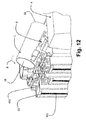
- Figures 10 to 13 The emptying of the tanks is done by tilting of these tanks 1 in the second direction ⁇ for emptying out the bucket.
- the second sense ⁇ is the same as the first direction ⁇ while on the figure 13 it is noted that the second direction of tilting is opposite, considering the point of view of the vats, in the first sense.
- the first and second senses are identical.
- the first means 6 tilting of the tanks 1 swing over the upright wall 23 of the bucket 2 which carries part of the locking means 5.
- This tilting is performed about a substantially longitudinal axis to this wall, c ' that is to say around an axis whose direction is that of the wall 23.
- retaining means of the vessel for example fixed to the base of the vessel. this tank, so as to further prevent its tilting over the wall 23.
- these tilting means are rotated by means of traction means 61 formed on the body of the second vehicle 9 and connected to the tilting means by means of connecting means such as straps 612.
- connecting means such as straps 612.
- each cradle 6 has its respective traction means, these traction means can also operate independently or not from each other, thus emptying all the tanks at the same time or empty them one by one.
- the fact of emptying one by one can have the advantage of avoiding a tilting of a mass too large at once and therefore a possible tilting of the vehicle, however, this has the disadvantage of being slower.
- the traction means 61 can be driven by an energy source of the second vehicle 9.
- the traction means of the embodiment of the figure 10 are replaced by lifting means 62 such as a crane that can lift the full tanks, these tanks are always connected to the tilting means 6 and locked to the bucket 2 by the locking means 5.
- the crane raises the full tanks one by one at their base, via connecting means 621 which connect the crane arm to the tanks.
- the tilting means further comprise selection means 63 of a tank 1 to empty from the plurality of tanks arranged in the bucket 2.
- these selection means 63 are in the form of hydraulic cylinders 631 translating vertically selecting carriages 632, these carriages 632 then selectively moving near the first tilting means of a vessel, the tilting vessel when the cylinder descends by carrying with it the carriage and thus the vessel.
- the movement of the carriages can be controlled manually, in particular by a user who chooses one of the carriages which must move by means of a control panel, or automatically.
- the selection trolleys can operate simultaneously or successively, allowing emptying several tanks simultaneously or emptying them successively.
- the figure 13 represents the emptying phase of the tank in an unloading zone according to the second embodiment of the assembly. As illustrated in this figure, it is not the tanks 1 'which are tilted directly by the tilting means 6' but the bucket 2 'which is tilted, leading indirectly tilting tanks. We could also imagine embodiments in which the bucket is tilted in part and the tanks are also tilted in part, so as to share the rocking movement between these two elements. In this example, the two superimposed tanks 1 'are emptied simultaneously outside the bucket 2' through an opening on one side of these tanks. It should be noted that, contrary to the first embodiment in which the tanks are transferred and emptied at two opposite walls of the bucket, the tanks of the second embodiment are transferred and empty at the same wall of the bucket. . Of course, one could also provide embodiments in which the tanks would be transferred and then empty at the location of two separate walls but not opposite.
Landscapes
- Engineering & Computer Science (AREA)
- Mechanical Engineering (AREA)
- Refuse-Collection Vehicles (AREA)
Abstract
Description
La présente invention concerne le domaine du transport terrestre de matières, et notamment de déchets.The present invention relates to the field of land transport of materials, including waste.
Plus particulièrement, l'invention concerne un ensemble de collecte et d'évacuation de déchets, notamment de déchets ménagers, en zone urbaine ou périurbaine.More particularly, the invention relates to a collection and removal of waste, including household waste, in urban or peri-urban areas.
Un des problèmes, à l'heure actuelle, dans le domaine de la collecte et de l'évacuation de déchets, est de pouvoir atteindre facilement les coeurs de ville pour y collecter les déchets et pouvoir les évacuer en périphérie de la ville vers des sites de déchargement tels que les décharges, les centres de retraitement, ou les centre de tri sélectif.One of the problems, at the moment, in the field of collection and disposal of waste, is to be able easily reach the hearts of city to collect the waste and to be able to evacuate them on the outskirts of the city towards sites such as landfills, reprocessing centers, or selective sorting centers.
Pour ce faire, il existe actuellement des systèmes classiques mettant en oeuvre des camions poubelle effectuant des circuits prédéterminés et collectant les déchets. De tels camions poubelle sont souvent massifs et peu rapides et comprennent une benne permettant de recueillir des déchets. Les déchets, accumulés dans des poubelles, sont versés dans la benne du camion par l'intermédiaire de moyens de basculement placés à l'arrière du camion qui basculent les poubelles. Une fois le circuit terminé, le camion repart en périphérie de la ville et se dirige, par exemple, vers un site de déchargement où il vide la benne.To do this, there are currently conventional systems implementing trash trucks performing predetermined circuits and collecting waste. Such garbage trucks are often massive and slow and include a bucket to collect waste. The waste, accumulated in garbage cans, are poured into the truck body by means of tilting means placed at the rear of the truck that tilt the bins. Once the circuit is over, the truck leaves the outskirts of the city and goes, for example, to an unloading site where he empties the bucket.
Cependant, un inconvénient de telles solutions est que les moyens mis en oeuvre, et notamment le camion poubelle, s'avèrent relativement gênants pour la circulation urbaine. En effet, de par leur encombrement relativement conséquent et leur faible vitesse, ils provoquent des blocages importants dans les rues ce qui n'est pas satisfaisant. Plus particulièrement, lorsque ces camions poubelle circulent dans les centres villes où la circulation urbaine est relativement dense, ils provoquent des ralentissements de la circulation ce qui est nuisible à la vie de la ville.However, a disadvantage of such solutions is that the means used, and in particular the garbage truck, are relatively troublesome for urban traffic. Indeed, because of their relatively large size and low speed, they cause significant blockages in the streets which is not satisfactory. More particularly, when these trash trucks circulate in the city centers where the urban traffic is relatively dense, they cause slowing of the traffic which is harmful to the life of the city.
En outre, de tels moyens se révèlent néfastes pour l'environnement de par l'impact carbone qu'ils possèdent et par leur consommation d'énergie ce qui n'est pas non plus satisfaisant. Ces moyens sont de plus relativement bruyants et développent une odeur peu agréable ce qui n'est pas acceptable pour les riverains.In addition, such means are harmful to the environment by the carbon impact they have and by their energy consumption which is also not satisfactory. These means are also relatively noisy and develop an unpleasant smell which is not acceptable to residents.
L'invention a notamment pour objectif de résoudre les inconvénients de l'art antérieur.The invention particularly aims to solve the disadvantages of the prior art.
Plus particulièrement un objectif de l'invention est de proposer une technique permettant de limiter l'interférence avec la circulation urbaine qui s'avère dense au coeur de ville (voitures, camions, véhicules à deux roues, piétons, ...) .More particularly, an object of the invention is to provide a technique for limiting interference with urban traffic that is dense in the heart of the city (cars, trucks, two-wheeled vehicles, pedestrians, ...).
Un autre objectif de l'invention est de fournir une technique permettant de limiter l'impact carbone lié à ces collectes et déplacements de déchets, et de limiter la consommation d'énergie tout en fournissant une solution relativement « propre ».Another object of the invention is to provide a technique for limiting the carbon impact related to these collections and waste movements, and to limit energy consumption while providing a relatively "clean" solution.
Encore un autre objectif de l'invention est de fournir une technique permettant d'optimiser la circulation du flux de déchets à collecter et à évacuer.Yet another object of the invention is to provide a technique for optimizing the circulation of the waste stream to be collected and discharged.
Enfin, un objectif de l'invention est de fournir une technique qui soit peu couteuse et simple à mettre en oeuvre.Finally, an object of the invention is to provide a technique that is inexpensive and simple to implement.
Ces objectifs, ainsi que d'autres qui apparaîtront par la suite, sont atteints à l'aide d'un ensemble de collecte et d'évacuation de déchets, notamment de déchets ménagers, en zone urbaine ou périurbaine, l'ensemble comprenant :
- au moins une cuve de stockage des déchets, la cuve présentant au moins une ouverture de réception de ces déchets ;
- une benne pouvant recevoir simultanément une pluralité de cuves à vider, la benne comprenant des parois dressées et un fond ;
- au moins un premier véhicule sur lequel est montée de manière amovible la cuve, pour l'amener vers la benne ;
- des moyens de transfert pour transférer la cuve depuis le véhicule dans la benne, et inversement,
- des moyens de verrouillage pour verrouiller de façon réversible la cuve à la benne, et
- des premiers moyens de basculement de la cuve, alors verrouillée à la benne.
- at least one waste storage tank, the tank having at least one opening for receiving the waste;
- a bucket that can simultaneously receive a plurality of tanks to be emptied, the bucket comprising erected walls and a bottom;
- at least one first vehicle on which is removably mounted the vessel, to bring it to the bucket;
- transfer means for transferring the tank from the vehicle into the body, and vice versa,
- locking means for reversibly locking the tank to the body, and
- first tilting means of the tank, then locked to the bucket.
Ainsi, l'invention propose une approche nouvelle et inventive permettant de limiter l'interférence entre l'ensemble de collecte et la circulation urbaine. En effet, le fait de mettre en oeuvre des cuves, dans lesquelles sont collectés des déchets, puis de transférer ces cuves dans des bennes qui sont situées à l'extérieur de la ville, permettent de diminuer l'encombrement des moyens qui pénètrent à l'intérieur de la ville et ainsi de limiter voire supprimer la gène occasionnée.Thus, the invention proposes a new and inventive approach to limit the interference between the collection assembly and the urban traffic. Indeed, the fact of implementing tanks, in which waste is collected, and then to transfer these tanks in skips that are located outside the city, reduce the clutter of the means that penetrate the city. interior of the city and thus to limit or even eliminate the gene caused.
En outre, cela permet d'optimiser la circulation du flux de déchets car une fois que les premiers véhicules ont chargé leurs cuves sur la benne, la benne peut être acheminée jusqu'à la zone de vidage tandis que les premiers véhicules repartent en ville avec des cuves vides, optimisant ainsi la vitesse de collecte et d'évacuation des déchets.In addition, this makes it possible to optimize the circulation of the waste stream because once the first vehicles have loaded their tanks on the bucket, the bucket can be transported to the dump area while the first vehicles leave the city with empty tanks, thus optimizing the speed of collection and disposal of waste.
Dans un mode de réalisation de l'invention, la benne comprend au moins un passage, ménagé sur au moins une de ses parois, pour passer la cuve dans la benne via les moyens de transfert.In one embodiment of the invention, the bucket comprises at least one passage, provided on at least one of its walls, to pass the tank into the bucket via the transfer means.
De ce fait, le transfert de la cuve depuis le premier véhicule jusqu'à la benne se trouve facilité par le passage qui est ménagé sur une de ses parois.As a result, the transfer of the tank from the first vehicle to the bucket is facilitated by the passage which is formed on one of its walls.
Dans un mode de réalisation particulier de l'invention, les moyens de transfert comprennent :
- un support de la cuve, monté mobile sur le premier véhicule, pour transporter la cuve sur le premier véhicule, et
- des deuxièmes moyens de basculement de la cuve pour faire basculer la cuve par rapport au support, entre le premier véhicule et la benne, de sorte que, amenée pleine, la cuve soit dressée dans la benne, avant d'être vidée via les premiers moyens de basculement, par-dessus une des parois dressées, sur une zone de déchargement.
- a tank support, mounted mobile on the first vehicle, for transporting the tank on the first vehicle, and
- second tilting means of the vessel for tilting the vessel relative to the carrier, between the first vehicle and the bucket, so that, brought full, the tank is erected in the bucket, before being emptied via the first means tilting, over one of the erected walls, on an unloading area.
Ainsi, cela permet de transférer la cuve depuis le premier véhicule vers la benne par des mouvements relativement simples à mettre en oeuvre mécaniquement, et de limiter le nombre de ces mouvements.Thus, it allows to transfer the tank from the first vehicle to the bucket by movements relatively simple to implement mechanically, and to limit the number of such movements.
Selon une variante de l'invention, le support et les deuxièmes moyens de basculement de la cuve sont montés respectivement sur le premier véhicule, et en partie sur les premiers moyens de basculement et la benne. Selon une autre variante de l'invention, le support et les deuxièmes moyens de basculement de la cuve sont montés respectivement sur le premier véhicule, et en partie sur le premier véhicule et la cuve.According to a variant of the invention, the support and the second tilting means of the tank are mounted respectively on the first vehicle, and in part on the first tilting means and the bucket. According to another variant of the invention, the support and the second tilting means of the vessel are mounted respectively on the first vehicle, and in part on the first vehicle and the vessel.
De ce fait, les moyens de transfert de l'ensemble sont répartis entre les différents « acteurs » de cet ensemble ce qui permet d'optimiser l'encombrement, notamment du premier véhicule, tout en facilitant la coopération de ces « acteurs ».As a result, the means of transfer of the whole are distributed among the various "actors" of this together which allows to optimize the size, including the first vehicle, while facilitating the cooperation of these "actors".
Selon un mode de réalisation de l'invention, les premiers et deuxièmes moyens de basculement de la cuve fonctionnent dans un premier et un deuxième sens et interviennent à l'endroit de deux parois distinctes.According to one embodiment of the invention, the first and second tilting means of the vessel operate in a first and a second direction and intervene at the location of two separate walls.
De cette manière, on répartit les moyens mis en oeuvre et l'activité au niveau des parois afin d'optimiser les efforts demandés à chacune des parois.In this way, the means used and the activity are distributed at the level of the walls in order to optimize the forces required for each of the walls.
Dans un mode de réalisation particulier de l'invention, l'ensemble comprend des moyens de déplacement de la cuve, pour déplacer la cuve dressée, dans la benne, entre le support de la cuve et une partie des premiers moyens de basculement, portée par la benne.In a particular embodiment of the invention, the assembly comprises means for moving the vessel, to move the upright vessel, in the bucket, between the support of the vessel and a part of the first tilting means, carried by the bucket.
De ce fait, on limite la consommation d'énergie de l'ensemble en mettant en oeuvre des moyens de déplacement qui permette d'éviter d'exercer des forces sur la cuve pour la placer directement sur les moyens de basculement de la benne.As a result, the energy consumption of the assembly is limited by implementing displacement means that make it possible to avoid exerting forces on the tank to place it directly on the tipping means of the body.
Selon une variante les moyens de déplacement de la cuve peuvent être montés sur le premier véhicule et la cuve.According to a variant, the means for moving the tank can be mounted on the first vehicle and the tank.
Ainsi, et de même que précédemment, on répartit l'activité au niveau de chacune des « entités » de l'ensemble tout en facilitant la coopération entre ces entités.Thus, and as before, the activity is distributed at the level of each of the "entities" of the group while facilitating cooperation between these entities.
Dans un autre mode de réalisation de l'invention, le support de la cuve est monté mobile sur le premier véhicule entre une première position de recul arrière, pour le basculement de la cuve, et une deuxième position avancée de chargement de déchets dans la cuve via une trémie de chargement équipant le premier véhicule.In another embodiment of the invention, the tank support is mounted to move on the first vehicle between a first rearward position for tilting the vessel and a second advanced position for loading waste into the vessel. via a loading hopper equipping the first vehicle.
De cette manière, on optimise les moyens mis en oeuvre dans l'invention, de par l'utilisation d'un unique support pour plusieurs phases de la collecte et de l'évacuation des déchets, tout en simplifiant le transfert de la cuve sur la benne par la réalisation de ce transfert au moyen de mouvements mécaniques simples.In this way, the means implemented in the invention are optimized by the use of a single support for several phases of the collection and disposal of waste, while simplifying the transfer of the vessel to the by the realization of this transfer by means of simple mechanical movements.
Dans un mode de réalisation particulier, l'ensemble comprend un second véhicule, plus lourd et volumineux que le premier véhicule et sur lequel est montée de manière amovible la benne, qui contient alors plusieurs cuves pleines, pour déplacer ladite benne vers la zone de déchargement.In a particular embodiment, the assembly comprises a second vehicle, heavier and larger than the first vehicle and on which is removably mounted the bucket, which then contains several full tanks, to move said bucket to the unloading area .
Ainsi, cela permet de déplacer la benne depuis la zone où elle est entreposée jusqu'à la zone de déchargement, et ce de manière simple et sans interférer avec les zones « sensibles » tel qu'un centre-ville.Thus, it allows to move the bucket from the area where it is stored to the unloading area, and this in a simple manner and without interfering with the "sensitive" areas such as a city center.
L'invention concerne également un procédé de collecte et d'évacuation de déchets, notamment de déchets ménagers, en zone urbaine ou périurbaine, le procédé comprenant des étapes où :
- on approche et immobilise, à proximité d'une benne adaptée à recevoir une pluralité de cuves, un premier véhicule portant une cuve pleine desdits déchets ;
- on transfère la cuve depuis le premier véhicule dans la benne, en reculant la cuve en porte-à-faux vis-à-vis d'un support qui soutient la cuve dans le premier véhicule, pendant son approche, et en laissant ensuite basculer la cuve par gravité, dans un premier sens de façon à la redresser dans la benne ;
- on verrouille de façon réversible la cuve à la benne, et,
- on bascule la cuve verrouillée, dans un deuxième sens, pour la vider sur une zone de déchargement, hors de la benne.
- approaching and immobilizing, near a bucket adapted to receive a plurality of tanks, a first vehicle carrying a full tank of said waste;
- the tank is transferred from the first vehicle into the bucket, by moving the cantilevered tank towards a support which supports the tank in the first vehicle, during its approach, and then allowing the tank to tilt. tank by gravity, in a first direction so as to straighten it in the bucket;
- reversibly locks the tank to the bucket, and,
- the locked tank is tilted, in a second direction, to empty it on an unloading area, out of the bucket.
Selon une variante du procédé, le transfert de la cuve depuis le premier véhicule dans la benne comprend un déplacement de la cuve dressée dans la benne, par des moyens de poussée portés par le premier véhicule, jusqu'à placer la cuve en position pour être verrouillée de façon réversible à une paroi dressée de la benne, afin de basculer la cuve par-dessus cette paroi lors de son vidage.According to a variant of the method, the transfer of the tank from the first vehicle into the bucket comprises a displacement of the tank erected in the bucket, by pushing means carried by the first vehicle, until the tank is placed in position to be reversibly locked to an upstanding wall of the bucket, in order to tilt the vessel over this wall during its emptying.
Dans un mode de réalisation particulier du procédé :
- on recule la cuve depuis le premier véhicule dans la benne par une action mécanique qui recule des bras latéraux liés au support et portant des pivots sur lesquels est montée la cuve,
- et/ou on aide au redressement final de la cuve en liant la cuve à un moyen de traction mu par le premier véhicule et qui tire la cuve vers sa base, dans le sens de son pivotement.
- the tank is moved back from the first vehicle in the bucket by a mechanical action which moves back lateral arms connected to the support and bearing pivots on which the tank is mounted,
- and / or assisting the final recovery of the tank by linking the tank to a traction means mu by the first vehicle and which pulls the tank towards its base, in the direction of its pivoting.
Dans un autre mode de réalisation du procédé, on finit le transfert de la cuve puis on la déplace dressée dans la benne :
- en mettant sur les moyens de déplacement la cuve dans la benne, et,
- en y faisant déplacer la cuve, par une action mécanique issue du premier véhicule et/ou recul du premier véhicule.
- putting on the means of displacement the tank in the bucket, and,
- by moving the tank, by a mechanical action from the first vehicle and / or retreat of the first vehicle.
D'autres caractéristiques et avantages de l'invention apparaitront plus clairement à la lecture de la description suivante d'un mode de réalisation, donné à titre de simple exemple illustratif et non limitatif, et des dessins annexés, parmi lesquels :
- la
figure 1 est une vue en perspective d'un premier véhicule portant une cuve, selon un premier mode de réalisation de l'invention ; - la
figure 2 est une vue en perspective de la benne selon le premier mode de réalisation de l'invention ; - les
figures 3 ,4 ,5 ,6 sont des vues latérales en coupe, illustrant quatre phases successives du transfert d'une cuve depuis un premier véhicule vers une benne, selon le premier mode de réalisation de l'invention ; - les
figures 7 et 8 illustrent deux phases successives de transfert de deux cuves depuis un premier véhicule vers une benne, selon un deuxième mode de réalisation de l'invention ; - la
figure 9 est une vue en perspective de la phase de transfert d'une benne sur un deuxième véhicule, selon le premier mode de réalisation de l'invention ; et - les
figures 10 ,11 ,12 ,13 sont des vues en perspective illustrant différents modes de réalisation de la phase de vidage de cuves dans une zone de déchargement.
- the
figure 1 is a perspective view of a first vehicle carrying a tank, according to a first embodiment of the invention; - the
figure 2 is a perspective view of the bucket according to the first embodiment of the invention; - the
figures 3 ,4 ,5 ,6 are sectional side views, illustrating four successive phases of the transfer of a tank from a first vehicle to a bucket, according to the first embodiment of the invention; - the
figures 7 and8 illustrate two successive phases of transfer of two tanks from a first vehicle to a bucket, according to a second embodiment of the invention; - the
figure 9 is a perspective view of the transfer phase of a bucket on a second vehicle, according to the first embodiment of the invention; and - the
figures 10 ,11 ,12 ,13 are perspective views illustrating different embodiments of the emptying phase of tanks in an unloading area.
On présente maintenant, en relation avec les
Comme illustré sur ces deux figures, l'ensemble comprend un premier véhicule 3 sur lequel est montée une cuve 1 de collecte de déchets, a priori des déchets ménagers. Le premier véhicule 3, autrement appelé véhicule de collecte, est un véhicule relativement léger et peu encombrant permettant de limiter la gêne occasionnée par la circulation de ce premier véhicule 3 au coeur d'une ville. Dans cet exemple, ce véhicule de collecte 3 est équipé d'un moteur à énergie propre et à faible consommation, tel qu'un moteur électrique, hybride ou à air comprimé, de manière à limiter l'impact environnemental et le coût énergétique. Ainsi, on conseille que le moteur 30 de propulsion du véhicule 3 soit à énergie propre, donc pas à combustion interne. Le premier véhicule 3 comprendra par ailleurs, de préférence, une trémie 31 de chargement de déchets ainsi que des moyens 32 (
Ce mode de réalisation illustre un premier véhicule adapté pour que sur celui-ci ne puisse être montée qu'une seule cuve, ce qui est préféré.This embodiment illustrates a first vehicle adapted so that on it can be mounted only one tank, which is preferred.
Cette cuve 1 de stockage des déchets présente, dans ce mode de réalisation, un profil cylindrique. Elle est montée de manière amovible vis-à-vis du véhicule de collecte 3 par l'intermédiaire d'un support 41. Elle comprend une ouverture 10 de réception des déchets qui peuvent être arrivés par la trémie 31. Cette ouverture peut servir également, dans ce mode de réalisation, à vider la cuve 1. On pourrait imaginer que la cuve possède plusieurs ouvertures, notamment une pour la remplir, une pour la vider, cette deuxième ouverture 110 pouvant être placée sur le côté de la cuve (voir
L'ensemble comprend également une benne 2. Cette benne 2, autrement appelée conteneur, comprend des (ici quatre) parois dressées 21, 22, 23, 24 (la paroi 21 dite frontale n'étant pas représentée sur les
Préférentiellement, cette benne sera placée à l'extérieur d'une zone de concentration urbaine importante de manière à ne pas gêner la circulation dans cette zone. Par exemple, on peut placer une telle benne 2 en périphérie du centre ville, les véhicules de collecte 3 acheminant les cuves pleines vers ou depuis cette benne 2, par trajets aller-retour.Preferably, this bucket will be placed outside a major urban concentration area so as not to hinder traffic in this area. For example, one can place such a
L'ensemble de collecte et d'évacuation de déchets comprend aussi des premiers moyens de transfert 4 de la cuve 1 sur la benne 2, des moyens de verrouillage 5 pour verrouiller de façon réversible la cuve 1 à la benne 2, et des premiers moyens 6 de basculement de la cuve 1, alors verrouillée à la benne 2, pour vider la cuve 1 à l'extérieur de la benne 2. Les moyens de verrouillage 5 sont ménagés sur une paroi de la benne et sur la/chaque cuve.The collection and disposal of waste also comprises first transfer means 4 of the
On recommande que le/chaque premier véhicule 3 soit pourvu d'une source de puissance, tel le moteur 30 ou une source annexe 300, qui alimente en énergie les premiers moyens 4 de transfert de la cuve, exclusivement.It is recommended that the / each
Ces moyens de transfert 4 permettent de transférer la cuve 1 transportée par le premier véhicule 3 sur la benne 2. Ils comprennent, dans cet exemple, le support 41 qui est monté sur le premier véhicule 1, et les deuxièmes moyens 42 de basculement de la cuve 1 qui permettent de faire basculer la cuve 1 par rapport au support 41 entre le premier véhicule 3 et la benne 2. Le support 41 de la cuve 1 est monté mobile sur le premier véhicule 3 entre une position de recul arrière (AR), pour le basculement de la cuve 1, et une deuxième position avancée pour le chargement de déchets dans la cuve 1 via la trémie 31. La position arrière (AR) est de préférence reculée en porte-à-faux vis-à-vis du véhicule, pour le transfert de la cuve vers la benne. Quant aux deuxièmes moyens de basculement 42, ils sont montés, dans ce mode de réalisation, en partie sur la cuve 1, la benne 2, le premier véhicule 3, et les premiers moyens de basculement 6. Dans cet exemple particulier, les deuxièmes moyens de basculement 42 sont sous la forme de pions de guidage 421 (montés sur les premiers moyens de basculement 6) circulant dans des rails de guidage 422 (montés sur la benne 2), et d'un câble (monté sur le premier véhicule 3, non représenté sur ces deux figures) relié à une attache (monté sur la cuve 1, non représenté sur ces deux figures).These transfer means 4 make it possible to transfer the
Ainsi, ces moyens de transfert 4 font passer la cuve 1 d'une position horizontale, lorsqu'elle est sur le support 41, à une position dressée dans la benne, par le biais des deuxièmes moyens de basculement 42.Thus, these transfer means 4 make the
Quant aux moyens de verrouillage 5, ils permettent de verrouiller la cuve à la benne de façon réversible. Dans cet exemple, les moyens de verrouillage sont sous la forme de « crochets » verticaux 51 ménagés le long d'une paroi dressée 23 de la benne 2 et coopérant avec une barre de maintien 52 ménagée sur les premiers moyens de basculement 6.As for the locking means 5, they allow to lock the tank to the bucket reversibly. In this example, the locking means are in the form of "hooks" vertical 51 formed along an
Ainsi, on préférera :
- que les premiers moyens 4 de transfert soient établis entre la cuve 1 et le
premier véhicule 3 exclusivement, et/ou, - que les moyens de verrouillage 5 et les premiers moyens de basculement 6 soient établis entre la/
chaque cuve 1 et la benne, exclusivement.
- that the first transfer means 4 are established between the
tank 1 and thefirst vehicle 3 exclusively, and / or, - that the locking means 5 and the first tilting means 6 are established between the / each
tank 1 and the bucket, exclusively.
Les deuxièmes moyens 42 de basculement sont montés en partie sur les premiers moyens de basculement et sur la benne 2, pour y faire basculer la cuve, à partir de la position reculée en porte-à-faux sur le support 41.The second means 42 of tilting are mounted in part on the first tilting means and on the
Dans cet exemple, les premiers moyens de basculement 6, autrement appelés berces, sont individuels. En d'autres termes, chaque cuve 1 vient coopérer avec des moyens de basculement 6 distincts. Ainsi, dans cet exemple, l'ensemble comprend trois « premiers moyens de basculement 6 » c'est-à-dire trois berces.In this example, the first switching means 6, otherwise called berces, are individual. In other words, each
On présente maintenant, en relation avec les
Préalablement au transfert de la cuve 1 pleine de déchets depuis le premier véhicule 3 vers la benne 2, le premier véhicule 3 s'approche et s'immobilise à proximité de la benne 2. Il se place en vis-à-vis d'un passage 26, et donc d'une berce 6. Dans cette phase, le support 41 soutient la cuve 1 dans le véhicule de collecte 3.Prior to the transfer of the
Une fois le véhicule de collecte 3 ainsi positionné, on transfère la cuve 1 pleine en la reculant, dans un premier temps, en porte-à-faux vis-à-vis du support 41. Pour ce faire, on translate la cuve 1 par une action mécanique qui recule des bras latéraux liés au support 41, donc ce support, lequel est alors en position de recul arrière. La
Dans un deuxième temps, et comme illustré en
Dans une troisième étape, et comme illustré en
Lors d'un processus inverse, c'est-à-dire lorsque l'on souhaite transférer une cuve depuis la benne vers le véhicule de collecte, on procède de manière inverse au transfert d'une cuve depuis le véhicule de collecte jusqu'à la benne. En d'autres termes, on effectue les étapes dans le sens inverse lorsqu'on souhaite transférer une cuve depuis la benne vers le véhicule de collecte. Ainsi :
- les moyens de transfert de la cuve ont posé la cuve, préférentiellement sur son
fond fixe 100, dans labenne 2, - et des moyens 8 de déplacement, au moins pour partie portés par la cuve et/ou le premier véhicule (moyen de poussée tels le câble ou tige 423 ou le support 41) ont déplacé la cuve posée dans la benne, entre le
premier véhicule 3 et une partie (611a,611b), portée par la benne, des premiers moyens de basculement 6.
- the tank transfer means have placed the tank, preferably on its fixed
bottom 100, in thebucket 2, - and displacement means 8, at least partly borne by the tank and / or the first vehicle (thrust means such as cable or
rod 423 or support 41) have moved the tank placed in the bucket, between thefirst vehicle 3 and a portion (611a, 611b) carried by the bucket, first tilting means 6.
On présente maintenant, en relation avec les
Dans ce mode de réalisation, l'ensemble comprend une cuve de stockage 1' qui présente un profil parallélépipédique et est montée sur un support 41' d'un premier véhicule de collecte 3'. L'ensemble comprend également une benne 2' qui possède trois parois dressées 21', 22', 23', et un passage ou une ouverture frontal (e) 26' prévu(e) pour faciliter le transfert des cuves 1' depuis le premier véhicule de collecte 3' vers la benne 2'. Une face dressée de la benne 2' est ainsi ouverte. A son sommet la benne est également ici ouverte.In this embodiment, the assembly comprises a storage tank 1 'which has a parallelepiped profile and is mounted on a support 41' of a first collection vehicle 3 '. The set includes also a bucket 2 'which has three erect walls 21', 22 ', 23', and a passage or a front opening (e) 26 'provided (e) to facilitate the transfer of the tanks 1' from the first collection vehicle 3 'to the bucket 2'. An erected face of the bucket 2 'is thus open. At its summit the bucket is also open here.
On retrouve, sur le premier véhicule 3', une trémie 31 de chargement de déchets, voire des moyens 32' de compression de ces déchets à travers le passage latéral 310'.There is, on the first vehicle 3 ', a
De même que l'ensemble du premier mode de réalisation, celui ici concerné comprend également des moyens de transfert 4' sous la forme du support 41' monté mobile en translation et en rotation sur le premier véhicule 3', et des deuxièmes moyens de basculement 42'. Dans cet exemple, les deuxièmes moyens de basculement 42' sont montés en partie sur la cuve 1' (par l'intermédiaire de pions de guidage 421'), sur la benne 2' (rails de guidage 422' dans lesquels peuvent circuler les pions de guidage 421') et sur le support 41' (crochet de retenue 423').As well as the whole of the first embodiment, the one concerned here also comprises transfer means 4 'in the form of the support 41' mounted mobile in translation and in rotation on the first vehicle 3 ', and second tilting means 42 '. In this example, the second tilting means 42 'are partly mounted on the tank 1' (via guiding pins 421 '), on the bucket 2' (guide rails 422 'in which the pieces may circulate). guide 421 ') and on the support 41' (retaining hook 423 ').
En outre, cet ensemble comprend également des moyens 5' de verrouillage de façon réversible de la cuve 1' dans la benne 2', ces moyens de verrouillage étant ménagés en partie sur la benne 2' et sur la cuve 1'.In addition, this assembly also comprises means 5 'reversibly locking the vessel 1' in the bucket 2 ', these locking means being formed in part on the bucket 2' and on the tank 1 '.
Enfin, l'ensemble comprend des premiers moyens (non représentés sur ces figures) de basculement de la cuve 1' qui sont placés en partie sur la benne 2' et en partie à distance de cette benne.Finally, the assembly comprises first means (not shown in these figures) of tilting of the tank 1 'which are placed partly on the bucket 2' and partly at a distance from this bucket.
Comme illustré sur ces
En ce qui concerne la cuve supérieure (
Ainsi :
- les deuxièmes moyens de basculement 42' :
- * montés en partie (repère 420') sur le premier véhicule (3') permettent de faire basculer la cuve,
- * et/ou, pour partie (repères 421',422') entre la cuve 1' et la benne 2' permettent de guider ensuite la cuve le long de la benne,
- le plateau élévateur 41' monté basculant sur le premier véhicule fait basculer la cuve via ces deuxièmes moyens (420') de basculement, et
- la benne et la cuve sont adaptées pour que la benne reçoive plusieurs cuves pleines qui sont superposées dans la benne via le plateau élévateur.
- the second tilting means 42 ':
- * partly mounted (mark 420 ') on the first vehicle (3') make it possible to tilt the tank,
- * and / or, partly (pins 421 ', 422') between the tank 1 'and the bucket 2' can then guide the tank along the bucket,
- the lifting platform 41 'pivotally mounted on the first vehicle tilts the vessel via these second means (420') of tilting, and
- the bucket and the tank are adapted so that the bucket receives several full tanks which are superimposed in the bucket via the elevator platform.
Les moyens 420' peuvent être des vérins.The means 420 'may be cylinders.
On recommande par ailleurs que les premiers moyens de basculement 6' soient disposés entre la benne 2' et le second véhicule 9' et soient mus par une source d'énergie autonome 300' du second véhicule.It is furthermore recommended that the first tilting means 6 'be arranged between the tipper 2' and the second vehicle 9 'and be driven by an autonomous energy source 300' of the second vehicle.
On présente maintenant, en relation avec la
Comme illustré sur cette
On présente par la suite, en relation avec les
Une fois la benne acheminée jusqu'à la zone de déchargement 50, on procède au vidage des cuves pleines.Once the bucket is routed to the
Pour cela, il a donc été procédé comme suit :
- a) on a collecté des déchets dans une cuve montée de façon amovible sur un premier type de véhicule 3 ou 3' ;
- b) ce premier type de véhicule a déplacé la cuve pleine vers une benne 2,2' « multicuves » ;
- c) on a alors pu transférer la cuve depuis le premier type de véhicule dans la benne ;
- d) on a pu réitérer au moins une fois les étapes a) à c),
- e) benne pleine, on l'a chargé sur un deuxième type de véhicule 9,9" plus lourd et volumineux que le premier;
- f) on a approché et immobilisé, à proximité d'une zone de déchargement 50 ce deuxième type de véhicule 9,9' porteur de la benne; et
- g) on a basculé les cuves pour les vider sur la zone de déchargement, hors de la benne.
- a) waste was collected in a tank removably mounted on a first type of
vehicle 3 or 3 '; - b) this first type of vehicle has moved the full tank to a 2.2 'multi-bucket bucket;
- c) it was then possible to transfer the tank from the first type of vehicle in the bucket;
- (d) at least once, steps a) to c) could be repeated,
- (e) a full bucket, loaded onto a second type of 9.9 "vehicle heavier and larger than the first;
- f) approaching and immobilized, near an unloading
zone 50, this second type of vehicle 9.9 'carrying the bucket; and - g) the tanks were tipped to empty them on the unloading area, outside the bucket.
Concernant le transfert de la/chaque cuve depuis le premier type de véhicule 3,3' vers la benne, il inclura donc favorablement une élévation et/ou un basculement d'au moins une des cuves.Regarding the transfer of the / each tank from the first type of
A ce sujet, les premiers moyens 6,6' de basculement de la/chaque cuve 1,1', alors verrouillée à la benne 2,2', permettront de la vider, à l'extérieur de cette benne, sur la zone 50 située donc en périphérie urbaine, par basculement :
- * de la cuve vis-à-vis de la benne (
Figures 10-12 ), - * et/ou de la benne (
Figure 13 ), la/chaque cuve concernée pouvant être fixe sur la benne.
- * of the tank vis-à-vis the bucket (
Figures 10-12 ) - * and / or bucket (
Figure 13 ), the / each relevant tank can be fixed on the bucket.
Et, dans le mode des
Comme déjà noté, ce vidage s'opèrera soit par l'ouverture 10 de réception, soit par une autre ouverture de la cuve dédiée à cela.As already noted, this emptying will take place either by the
Comme illustré sur les
Dans le mode de réalisation de la
Dans le mode de réalisation de la
Dans le mode de réalisation de la
La
On pourrait également prévoir un mode de réalisation dans lequel les troisièmes moyens de basculement et les premiers moyens de basculement sont confondus. On pourrait en outre prévoir des modes de réalisation dans lesquels la benne est placée à l'origine sur le second véhicule, de sorte à supprimer l'étape de transfert de la benne sur ce second véhicule.An embodiment could also be provided in which the third tilting means and the first tilting means are merged. In addition, it is possible to provide embodiments in which the bucket is placed at the origin on the second vehicle, so as to eliminate the step of transferring the bucket to this second vehicle.
Claims (13)
Applications Claiming Priority (1)
| Application Number | Priority Date | Filing Date | Title |
|---|---|---|---|
| FR1351183A FR3001960A1 (en) | 2013-02-12 | 2013-02-12 | HOUSEHOLD WASTE COLLECTION AND EXHAUST ASSEMBLY |
Publications (2)
| Publication Number | Publication Date |
|---|---|
| EP2765097A1 true EP2765097A1 (en) | 2014-08-13 |
| EP2765097B1 EP2765097B1 (en) | 2016-05-25 |
Family
ID=48468512
Family Applications (1)
| Application Number | Title | Priority Date | Filing Date |
|---|---|---|---|
| EP14154273.8A Not-in-force EP2765097B1 (en) | 2013-02-12 | 2014-02-07 | Assembly for collecting and disposing of household refuse |
Country Status (3)
| Country | Link |
|---|---|
| EP (1) | EP2765097B1 (en) |
| FR (1) | FR3001960A1 (en) |
| SG (1) | SG2014010268A (en) |
Citations (8)
| Publication number | Priority date | Publication date | Assignee | Title |
|---|---|---|---|---|
| DE1239619B (en) * | 1962-09-17 | 1967-04-27 | Feka Fabrik Fuer Spezialfahrze | Refuse container transport vehicle |
| FR2330612A1 (en) * | 1975-11-04 | 1977-06-03 | Karlsruhe Augsburg Iweka | Refuse collection truck with separable containers - has loading arms and container connected via self driven hydraulic lifting gear |
| EP0163870A2 (en) * | 1984-05-29 | 1985-12-11 | Edelhoff M.S.T.S. Gmbh | Apparatus for raising and removing refuse containers from a refuse vehicle |
| EP0243316A1 (en) * | 1986-04-25 | 1987-10-28 | Hydro Mécanique Research S.A. | Transferring device comprising refuse containers |
| DE4303349C1 (en) * | 1993-02-05 | 1994-05-19 | Gert Richter | Transporter for waste materials - has platform chassis with elongated containers mounted transversely and tipped by crane on vehicle |
| US20050019147A1 (en) * | 2003-07-22 | 2005-01-27 | Gary Flerchinger | Refuse collection vehicle and method with stackable refuse storage container |
| WO2010133265A1 (en) * | 2009-05-22 | 2010-11-25 | Anconambiente S.P.A. | Method and equipment for collecting household refuse |
| US20110194920A1 (en) * | 2010-02-05 | 2011-08-11 | Thomas Gesuale | Jezco container inside a jezco waste collection truck |
-
2013
- 2013-02-12 FR FR1351183A patent/FR3001960A1/en active Pending
-
2014
- 2014-02-07 EP EP14154273.8A patent/EP2765097B1/en not_active Not-in-force
- 2014-02-10 SG SG2014010268A patent/SG2014010268A/en unknown
Patent Citations (8)
| Publication number | Priority date | Publication date | Assignee | Title |
|---|---|---|---|---|
| DE1239619B (en) * | 1962-09-17 | 1967-04-27 | Feka Fabrik Fuer Spezialfahrze | Refuse container transport vehicle |
| FR2330612A1 (en) * | 1975-11-04 | 1977-06-03 | Karlsruhe Augsburg Iweka | Refuse collection truck with separable containers - has loading arms and container connected via self driven hydraulic lifting gear |
| EP0163870A2 (en) * | 1984-05-29 | 1985-12-11 | Edelhoff M.S.T.S. Gmbh | Apparatus for raising and removing refuse containers from a refuse vehicle |
| EP0243316A1 (en) * | 1986-04-25 | 1987-10-28 | Hydro Mécanique Research S.A. | Transferring device comprising refuse containers |
| DE4303349C1 (en) * | 1993-02-05 | 1994-05-19 | Gert Richter | Transporter for waste materials - has platform chassis with elongated containers mounted transversely and tipped by crane on vehicle |
| US20050019147A1 (en) * | 2003-07-22 | 2005-01-27 | Gary Flerchinger | Refuse collection vehicle and method with stackable refuse storage container |
| WO2010133265A1 (en) * | 2009-05-22 | 2010-11-25 | Anconambiente S.P.A. | Method and equipment for collecting household refuse |
| US20110194920A1 (en) * | 2010-02-05 | 2011-08-11 | Thomas Gesuale | Jezco container inside a jezco waste collection truck |
Also Published As
| Publication number | Publication date |
|---|---|
| SG2014010268A (en) | 2014-09-26 |
| EP2765097B1 (en) | 2016-05-25 |
| FR3001960A1 (en) | 2014-08-15 |
Similar Documents
| Publication | Publication Date | Title |
|---|---|---|
| EP2922773A1 (en) | Bin for a rubbish collection vehicle with improved compaction | |
| EP0099280B1 (en) | Device for the stocking and fast handling of unit loads, in particular for loading a road transport vehicle | |
| FR2587291A1 (en) | Motorised trolley which can be used in supermarkets and hypermarkets | |
| EP2765097B1 (en) | Assembly for collecting and disposing of household refuse | |
| EP2765096B1 (en) | Assembly for collecting and disposing of household refuse | |
| EP2922772B1 (en) | Rubbish collection vehicle with an improved container lifter | |
| WO2006111620A1 (en) | Special wheeled containers, their transporting trucks, and uses thereof | |
| EP3590870A1 (en) | Biowaste collection system | |
| FR2685681A1 (en) | TRANSPORT VEHICLE FOR THE COLLECTION OF HOUSEHOLD GARBAGE. | |
| LU86189A1 (en) | AUTOMATED INSTALLATION FOR BRIQUETTING THE INTERIOR WALL OF AN ENCLOSURE | |
| FR2919239A1 (en) | Luggage container transferring vehicle for use with aircraft, has traction engine removably hooked on trailer for simultaneously towing trailer and ensuring transfer of containers through transfer platform | |
| WO2008113897A1 (en) | Containers particularly intended for collecting domestic waste in rural and urban areas, collecting vehicles and trailers thereof, vehicle for transporting them to a processing centre and maintenance thereof | |
| FR2727658A1 (en) | MATERIAL FOR LIFTING AND HANDLING MISCELLANEOUS LOADS, ASSOCIATED WITH A VEHICLE | |
| FR2552581A1 (en) | SYSTEM FOR TRANSFERRING NUCLEAR COMBUSTIBLE ASSEMBLIES | |
| FR2611682A1 (en) | Movable support or service platform for bringing a vehicle into a raised position | |
| EP4056500A1 (en) | Arm for collecting containers for a biowaste pick-up vehicle. | |
| CN219949814U (en) | Dumping garbage bin auxiliary device | |
| FR2946967A1 (en) | Household wastes e.g. glasses, evacuating method for urban zone, involves collecting contents of containers by dump or crane lorry, and transporting contents towards treatment installation at speed higher than maximum speed of vehicle | |
| FR2674810A1 (en) | Trolley for handling a load equipped with wheels | |
| FR2868743A1 (en) | Special container for transporting e.g. building waste, has castor wheel to laterally load using portals of cargo truck and trailers, which are provided with extendable platforms to carry out lateral loading/unloading of container | |
| FR3037050A1 (en) | DEVICE FOR LOADING, ELEVATING AND DISCHARGING WASTE INTO A DUMP | |
| FR2870208A1 (en) | Luggage transferring installation for air terminal, has loading/unloading device to connect cargo compartment and trolley and to transfer luggage by rolling luggage rows perpendicular to their longitudinal axis, between device and trolley | |
| EP1686077A1 (en) | Vehicle for collecting of products, especially refuse, stored in recptacles, especially refuse receptacles | |
| EP0002637B1 (en) | Device for storing and laying juxtaposed floor sections, especially for merry-go-rounds | |
| EP0429355A1 (en) | Device assuring a charge remains horizontal while being transferred from a higher to a lower level |
Legal Events
| Date | Code | Title | Description |
|---|---|---|---|
| PUAI | Public reference made under article 153(3) epc to a published international application that has entered the european phase |
Free format text: ORIGINAL CODE: 0009012 |
|
| 17P | Request for examination filed |
Effective date: 20140207 |
|
| AK | Designated contracting states |
Kind code of ref document: A1 Designated state(s): AL AT BE BG CH CY CZ DE DK EE ES FI FR GB GR HR HU IE IS IT LI LT LU LV MC MK MT NL NO PL PT RO RS SE SI SK SM TR |
|
| AX | Request for extension of the european patent |
Extension state: BA ME |
|
| R17P | Request for examination filed (corrected) |
Effective date: 20141023 |
|
| RBV | Designated contracting states (corrected) |
Designated state(s): AL AT BE BG CH CY CZ DE DK EE ES FI FR GB GR HR HU IE IS IT LI LT LU LV MC MK MT NL NO PL PT RO RS SE SI SK SM TR |
|
| GRAP | Despatch of communication of intention to grant a patent |
Free format text: ORIGINAL CODE: EPIDOSNIGR1 |
|
| RIC1 | Information provided on ipc code assigned before grant |
Ipc: B65F 3/00 20060101AFI20151028BHEP Ipc: B65F 3/08 20060101ALI20151028BHEP |
|
| INTG | Intention to grant announced |
Effective date: 20151125 |
|
| GRAS | Grant fee paid |
Free format text: ORIGINAL CODE: EPIDOSNIGR3 |
|
| GRAP | Despatch of communication of intention to grant a patent |
Free format text: ORIGINAL CODE: EPIDOSNIGR1 |
|
| INTG | Intention to grant announced |
Effective date: 20160317 |
|
| GRAA | (expected) grant |
Free format text: ORIGINAL CODE: 0009210 |
|
| AK | Designated contracting states |
Kind code of ref document: B1 Designated state(s): AL AT BE BG CH CY CZ DE DK EE ES FI FR GB GR HR HU IE IS IT LI LT LU LV MC MK MT NL NO PL PT RO RS SE SI SK SM TR |
|
| REG | Reference to a national code |
Ref country code: GB Ref legal event code: FG4D Free format text: NOT ENGLISH |
|
| REG | Reference to a national code |
Ref country code: CH Ref legal event code: EP |
|
| REG | Reference to a national code |
Ref country code: IE Ref legal event code: FG4D Free format text: LANGUAGE OF EP DOCUMENT: FRENCH Ref country code: AT Ref legal event code: REF Ref document number: 802102 Country of ref document: AT Kind code of ref document: T Effective date: 20160615 |
|
| REG | Reference to a national code |
Ref country code: DE Ref legal event code: R096 Ref document number: 602014002011 Country of ref document: DE |
|
| REG | Reference to a national code |
Ref country code: LT Ref legal event code: MG4D |
|
| REG | Reference to a national code |
Ref country code: NL Ref legal event code: MP Effective date: 20160525 |
|
| PG25 | Lapsed in a contracting state [announced via postgrant information from national office to epo] |
Ref country code: FI Free format text: LAPSE BECAUSE OF FAILURE TO SUBMIT A TRANSLATION OF THE DESCRIPTION OR TO PAY THE FEE WITHIN THE PRESCRIBED TIME-LIMIT Effective date: 20160525 Ref country code: NL Free format text: LAPSE BECAUSE OF FAILURE TO SUBMIT A TRANSLATION OF THE DESCRIPTION OR TO PAY THE FEE WITHIN THE PRESCRIBED TIME-LIMIT Effective date: 20160525 Ref country code: NO Free format text: LAPSE BECAUSE OF FAILURE TO SUBMIT A TRANSLATION OF THE DESCRIPTION OR TO PAY THE FEE WITHIN THE PRESCRIBED TIME-LIMIT Effective date: 20160825 Ref country code: LT Free format text: LAPSE BECAUSE OF FAILURE TO SUBMIT A TRANSLATION OF THE DESCRIPTION OR TO PAY THE FEE WITHIN THE PRESCRIBED TIME-LIMIT Effective date: 20160525 |
|
| REG | Reference to a national code |
Ref country code: AT Ref legal event code: MK05 Ref document number: 802102 Country of ref document: AT Kind code of ref document: T Effective date: 20160525 |
|
| PG25 | Lapsed in a contracting state [announced via postgrant information from national office to epo] |
Ref country code: RS Free format text: LAPSE BECAUSE OF FAILURE TO SUBMIT A TRANSLATION OF THE DESCRIPTION OR TO PAY THE FEE WITHIN THE PRESCRIBED TIME-LIMIT Effective date: 20160525 Ref country code: GR Free format text: LAPSE BECAUSE OF FAILURE TO SUBMIT A TRANSLATION OF THE DESCRIPTION OR TO PAY THE FEE WITHIN THE PRESCRIBED TIME-LIMIT Effective date: 20160826 Ref country code: ES Free format text: LAPSE BECAUSE OF FAILURE TO SUBMIT A TRANSLATION OF THE DESCRIPTION OR TO PAY THE FEE WITHIN THE PRESCRIBED TIME-LIMIT Effective date: 20160525 Ref country code: SE Free format text: LAPSE BECAUSE OF FAILURE TO SUBMIT A TRANSLATION OF THE DESCRIPTION OR TO PAY THE FEE WITHIN THE PRESCRIBED TIME-LIMIT Effective date: 20160525 Ref country code: LV Free format text: LAPSE BECAUSE OF FAILURE TO SUBMIT A TRANSLATION OF THE DESCRIPTION OR TO PAY THE FEE WITHIN THE PRESCRIBED TIME-LIMIT Effective date: 20160525 Ref country code: PT Free format text: LAPSE BECAUSE OF FAILURE TO SUBMIT A TRANSLATION OF THE DESCRIPTION OR TO PAY THE FEE WITHIN THE PRESCRIBED TIME-LIMIT Effective date: 20160926 |
|
| REG | Reference to a national code |
Ref country code: FR Ref legal event code: PLFP Year of fee payment: 4 |
|
| PG25 | Lapsed in a contracting state [announced via postgrant information from national office to epo] |
Ref country code: IT Free format text: LAPSE BECAUSE OF FAILURE TO SUBMIT A TRANSLATION OF THE DESCRIPTION OR TO PAY THE FEE WITHIN THE PRESCRIBED TIME-LIMIT Effective date: 20160525 |
|
| PG25 | Lapsed in a contracting state [announced via postgrant information from national office to epo] |
Ref country code: RO Free format text: LAPSE BECAUSE OF FAILURE TO SUBMIT A TRANSLATION OF THE DESCRIPTION OR TO PAY THE FEE WITHIN THE PRESCRIBED TIME-LIMIT Effective date: 20160525 Ref country code: EE Free format text: LAPSE BECAUSE OF FAILURE TO SUBMIT A TRANSLATION OF THE DESCRIPTION OR TO PAY THE FEE WITHIN THE PRESCRIBED TIME-LIMIT Effective date: 20160525 Ref country code: DK Free format text: LAPSE BECAUSE OF FAILURE TO SUBMIT A TRANSLATION OF THE DESCRIPTION OR TO PAY THE FEE WITHIN THE PRESCRIBED TIME-LIMIT Effective date: 20160525 Ref country code: SK Free format text: LAPSE BECAUSE OF FAILURE TO SUBMIT A TRANSLATION OF THE DESCRIPTION OR TO PAY THE FEE WITHIN THE PRESCRIBED TIME-LIMIT Effective date: 20160525 Ref country code: CZ Free format text: LAPSE BECAUSE OF FAILURE TO SUBMIT A TRANSLATION OF THE DESCRIPTION OR TO PAY THE FEE WITHIN THE PRESCRIBED TIME-LIMIT Effective date: 20160525 |
|
| PG25 | Lapsed in a contracting state [announced via postgrant information from national office to epo] |
Ref country code: SM Free format text: LAPSE BECAUSE OF FAILURE TO SUBMIT A TRANSLATION OF THE DESCRIPTION OR TO PAY THE FEE WITHIN THE PRESCRIBED TIME-LIMIT Effective date: 20160525 Ref country code: AT Free format text: LAPSE BECAUSE OF FAILURE TO SUBMIT A TRANSLATION OF THE DESCRIPTION OR TO PAY THE FEE WITHIN THE PRESCRIBED TIME-LIMIT Effective date: 20160525 Ref country code: PL Free format text: LAPSE BECAUSE OF FAILURE TO SUBMIT A TRANSLATION OF THE DESCRIPTION OR TO PAY THE FEE WITHIN THE PRESCRIBED TIME-LIMIT Effective date: 20160525 |
|
| REG | Reference to a national code |
Ref country code: DE Ref legal event code: R097 Ref document number: 602014002011 Country of ref document: DE |
|
| PLBE | No opposition filed within time limit |
Free format text: ORIGINAL CODE: 0009261 |
|
| STAA | Information on the status of an ep patent application or granted ep patent |
Free format text: STATUS: NO OPPOSITION FILED WITHIN TIME LIMIT |
|
| 26N | No opposition filed |
Effective date: 20170228 |
|
| PG25 | Lapsed in a contracting state [announced via postgrant information from national office to epo] |
Ref country code: BE Free format text: LAPSE BECAUSE OF NON-PAYMENT OF DUE FEES Effective date: 20170228 Ref country code: SI Free format text: LAPSE BECAUSE OF FAILURE TO SUBMIT A TRANSLATION OF THE DESCRIPTION OR TO PAY THE FEE WITHIN THE PRESCRIBED TIME-LIMIT Effective date: 20160525 |
|
| PG25 | Lapsed in a contracting state [announced via postgrant information from national office to epo] |
Ref country code: MC Free format text: LAPSE BECAUSE OF FAILURE TO SUBMIT A TRANSLATION OF THE DESCRIPTION OR TO PAY THE FEE WITHIN THE PRESCRIBED TIME-LIMIT Effective date: 20160525 |
|
| REG | Reference to a national code |
Ref country code: CH Ref legal event code: PL |
|
| PG25 | Lapsed in a contracting state [announced via postgrant information from national office to epo] |
Ref country code: CH Free format text: LAPSE BECAUSE OF NON-PAYMENT OF DUE FEES Effective date: 20170228 Ref country code: LI Free format text: LAPSE BECAUSE OF NON-PAYMENT OF DUE FEES Effective date: 20170228 |
|
| REG | Reference to a national code |
Ref country code: IE Ref legal event code: MM4A |
|
| REG | Reference to a national code |
Ref country code: FR Ref legal event code: PLFP Year of fee payment: 5 |
|
| PG25 | Lapsed in a contracting state [announced via postgrant information from national office to epo] |
Ref country code: LU Free format text: LAPSE BECAUSE OF NON-PAYMENT OF DUE FEES Effective date: 20170207 |
|
| REG | Reference to a national code |
Ref country code: BE Ref legal event code: MM Effective date: 20170228 |
|
| PG25 | Lapsed in a contracting state [announced via postgrant information from national office to epo] |
Ref country code: IE Free format text: LAPSE BECAUSE OF NON-PAYMENT OF DUE FEES Effective date: 20170207 |
|
| PG25 | Lapsed in a contracting state [announced via postgrant information from national office to epo] |
Ref country code: MT Free format text: LAPSE BECAUSE OF FAILURE TO SUBMIT A TRANSLATION OF THE DESCRIPTION OR TO PAY THE FEE WITHIN THE PRESCRIBED TIME-LIMIT Effective date: 20160525 |
|
| PG25 | Lapsed in a contracting state [announced via postgrant information from national office to epo] |
Ref country code: AL Free format text: LAPSE BECAUSE OF FAILURE TO SUBMIT A TRANSLATION OF THE DESCRIPTION OR TO PAY THE FEE WITHIN THE PRESCRIBED TIME-LIMIT Effective date: 20160525 |
|
| PG25 | Lapsed in a contracting state [announced via postgrant information from national office to epo] |
Ref country code: HU Free format text: LAPSE BECAUSE OF FAILURE TO SUBMIT A TRANSLATION OF THE DESCRIPTION OR TO PAY THE FEE WITHIN THE PRESCRIBED TIME-LIMIT; INVALID AB INITIO Effective date: 20140207 |
|
| PG25 | Lapsed in a contracting state [announced via postgrant information from national office to epo] |
Ref country code: BG Free format text: LAPSE BECAUSE OF FAILURE TO SUBMIT A TRANSLATION OF THE DESCRIPTION OR TO PAY THE FEE WITHIN THE PRESCRIBED TIME-LIMIT Effective date: 20160525 |
|
| PG25 | Lapsed in a contracting state [announced via postgrant information from national office to epo] |
Ref country code: CY Free format text: LAPSE BECAUSE OF NON-PAYMENT OF DUE FEES Effective date: 20160525 |
|
| PG25 | Lapsed in a contracting state [announced via postgrant information from national office to epo] |
Ref country code: MK Free format text: LAPSE BECAUSE OF FAILURE TO SUBMIT A TRANSLATION OF THE DESCRIPTION OR TO PAY THE FEE WITHIN THE PRESCRIBED TIME-LIMIT Effective date: 20160525 |
|
| PG25 | Lapsed in a contracting state [announced via postgrant information from national office to epo] |
Ref country code: TR Free format text: LAPSE BECAUSE OF FAILURE TO SUBMIT A TRANSLATION OF THE DESCRIPTION OR TO PAY THE FEE WITHIN THE PRESCRIBED TIME-LIMIT Effective date: 20160525 |
|
| PGFP | Annual fee paid to national office [announced via postgrant information from national office to epo] |
Ref country code: GB Payment date: 20200227 Year of fee payment: 7 Ref country code: DE Payment date: 20200227 Year of fee payment: 7 |
|
| PG25 | Lapsed in a contracting state [announced via postgrant information from national office to epo] |
Ref country code: HR Free format text: LAPSE BECAUSE OF FAILURE TO SUBMIT A TRANSLATION OF THE DESCRIPTION OR TO PAY THE FEE WITHIN THE PRESCRIBED TIME-LIMIT Effective date: 20160525 |
|
| PGFP | Annual fee paid to national office [announced via postgrant information from national office to epo] |
Ref country code: FR Payment date: 20200226 Year of fee payment: 7 |
|
| PG25 | Lapsed in a contracting state [announced via postgrant information from national office to epo] |
Ref country code: IS Free format text: LAPSE BECAUSE OF FAILURE TO SUBMIT A TRANSLATION OF THE DESCRIPTION OR TO PAY THE FEE WITHIN THE PRESCRIBED TIME-LIMIT Effective date: 20160925 |
|
| REG | Reference to a national code |
Ref country code: DE Ref legal event code: R119 Ref document number: 602014002011 Country of ref document: DE |
|
| GBPC | Gb: european patent ceased through non-payment of renewal fee |
Effective date: 20210207 |
|
| PG25 | Lapsed in a contracting state [announced via postgrant information from national office to epo] |
Ref country code: DE Free format text: LAPSE BECAUSE OF NON-PAYMENT OF DUE FEES Effective date: 20210901 Ref country code: GB Free format text: LAPSE BECAUSE OF NON-PAYMENT OF DUE FEES Effective date: 20210207 Ref country code: FR Free format text: LAPSE BECAUSE OF NON-PAYMENT OF DUE FEES Effective date: 20210228 |