EP2763600B1 - Dispositif de réparation de hernie - Google Patents
Dispositif de réparation de hernie Download PDFInfo
- Publication number
- EP2763600B1 EP2763600B1 EP12834873.7A EP12834873A EP2763600B1 EP 2763600 B1 EP2763600 B1 EP 2763600B1 EP 12834873 A EP12834873 A EP 12834873A EP 2763600 B1 EP2763600 B1 EP 2763600B1
- Authority
- EP
- European Patent Office
- Prior art keywords
- mesh
- filaments
- hernia repair
- tissue
- repair device
- Prior art date
- Legal status (The legal status is an assumption and is not a legal conclusion. Google has not performed a legal analysis and makes no representation as to the accuracy of the status listed.)
- Active
Links
- 230000008439 repair process Effects 0.000 title claims description 61
- 206010019909 Hernia Diseases 0.000 title claims description 59
- 230000007547 defect Effects 0.000 claims description 48
- 230000001681 protective effect Effects 0.000 claims description 15
- 238000003780 insertion Methods 0.000 claims description 7
- 230000037431 insertion Effects 0.000 claims description 7
- 210000003484 anatomy Anatomy 0.000 claims description 4
- 230000006378 damage Effects 0.000 description 12
- 208000014674 injury Diseases 0.000 description 9
- 208000027418 Wounds and injury Diseases 0.000 description 8
- 239000000463 material Substances 0.000 description 8
- 238000000034 method Methods 0.000 description 7
- 210000003815 abdominal wall Anatomy 0.000 description 6
- 239000012867 bioactive agent Substances 0.000 description 4
- 239000000560 biocompatible material Substances 0.000 description 3
- 150000001875 compounds Chemical class 0.000 description 3
- 241000287107 Passer Species 0.000 description 2
- 230000000181 anti-adherent effect Effects 0.000 description 2
- 239000012620 biological material Substances 0.000 description 2
- 230000031018 biological processes and functions Effects 0.000 description 2
- 230000004048 modification Effects 0.000 description 2
- 238000012986 modification Methods 0.000 description 2
- 230000000717 retained effect Effects 0.000 description 2
- 239000000126 substance Substances 0.000 description 2
- 230000008733 trauma Effects 0.000 description 2
- 238000003466 welding Methods 0.000 description 2
- 208000012260 Accidental injury Diseases 0.000 description 1
- 210000000683 abdominal cavity Anatomy 0.000 description 1
- 238000004873 anchoring Methods 0.000 description 1
- 230000008901 benefit Effects 0.000 description 1
- 230000001680 brushing effect Effects 0.000 description 1
- 230000024245 cell differentiation Effects 0.000 description 1
- 230000010261 cell growth Effects 0.000 description 1
- 239000003795 chemical substances by application Substances 0.000 description 1
- 239000010408 film Substances 0.000 description 1
- 239000000499 gel Substances 0.000 description 1
- 230000035876 healing Effects 0.000 description 1
- 230000028993 immune response Effects 0.000 description 1
- 238000002513 implantation Methods 0.000 description 1
- 239000007788 liquid Substances 0.000 description 1
- 239000003589 local anesthetic agent Substances 0.000 description 1
- 230000007246 mechanism Effects 0.000 description 1
- 239000007769 metal material Substances 0.000 description 1
- 239000000203 mixture Substances 0.000 description 1
- 229920000642 polymer Polymers 0.000 description 1
- 239000000843 powder Substances 0.000 description 1
- 230000008569 process Effects 0.000 description 1
- 230000000069 prophylactic effect Effects 0.000 description 1
- 230000002787 reinforcement Effects 0.000 description 1
- 238000001356 surgical procedure Methods 0.000 description 1
- 230000001225 therapeutic effect Effects 0.000 description 1
- 230000008467 tissue growth Effects 0.000 description 1
- 210000001835 viscera Anatomy 0.000 description 1
Images


Classifications
-
- A—HUMAN NECESSITIES
- A61—MEDICAL OR VETERINARY SCIENCE; HYGIENE
- A61F—FILTERS IMPLANTABLE INTO BLOOD VESSELS; PROSTHESES; DEVICES PROVIDING PATENCY TO, OR PREVENTING COLLAPSING OF, TUBULAR STRUCTURES OF THE BODY, e.g. STENTS; ORTHOPAEDIC, NURSING OR CONTRACEPTIVE DEVICES; FOMENTATION; TREATMENT OR PROTECTION OF EYES OR EARS; BANDAGES, DRESSINGS OR ABSORBENT PADS; FIRST-AID KITS
- A61F2/00—Filters implantable into blood vessels; Prostheses, i.e. artificial substitutes or replacements for parts of the body; Appliances for connecting them with the body; Devices providing patency to, or preventing collapsing of, tubular structures of the body, e.g. stents
- A61F2/0063—Implantable repair or support meshes, e.g. hernia meshes
-
- A—HUMAN NECESSITIES
- A61—MEDICAL OR VETERINARY SCIENCE; HYGIENE
- A61B—DIAGNOSIS; SURGERY; IDENTIFICATION
- A61B17/00—Surgical instruments, devices or methods, e.g. tourniquets
- A61B17/04—Surgical instruments, devices or methods, e.g. tourniquets for suturing wounds; Holders or packages for needles or suture materials
- A61B17/06—Needles ; Sutures; Needle-suture combinations; Holders or packages for needles or suture materials
-
- A—HUMAN NECESSITIES
- A61—MEDICAL OR VETERINARY SCIENCE; HYGIENE
- A61B—DIAGNOSIS; SURGERY; IDENTIFICATION
- A61B17/00—Surgical instruments, devices or methods, e.g. tourniquets
- A61B17/04—Surgical instruments, devices or methods, e.g. tourniquets for suturing wounds; Holders or packages for needles or suture materials
- A61B17/0493—Protective devices for suturing, i.e. for protecting the patient's organs or the operator
-
- A—HUMAN NECESSITIES
- A61—MEDICAL OR VETERINARY SCIENCE; HYGIENE
- A61B—DIAGNOSIS; SURGERY; IDENTIFICATION
- A61B17/00—Surgical instruments, devices or methods, e.g. tourniquets
- A61B17/04—Surgical instruments, devices or methods, e.g. tourniquets for suturing wounds; Holders or packages for needles or suture materials
- A61B17/06—Needles ; Sutures; Needle-suture combinations; Holders or packages for needles or suture materials
- A61B17/06166—Sutures
- A61B2017/06176—Sutures with protrusions, e.g. barbs
-
- A—HUMAN NECESSITIES
- A61—MEDICAL OR VETERINARY SCIENCE; HYGIENE
- A61F—FILTERS IMPLANTABLE INTO BLOOD VESSELS; PROSTHESES; DEVICES PROVIDING PATENCY TO, OR PREVENTING COLLAPSING OF, TUBULAR STRUCTURES OF THE BODY, e.g. STENTS; ORTHOPAEDIC, NURSING OR CONTRACEPTIVE DEVICES; FOMENTATION; TREATMENT OR PROTECTION OF EYES OR EARS; BANDAGES, DRESSINGS OR ABSORBENT PADS; FIRST-AID KITS
- A61F2220/00—Fixations or connections for prostheses classified in groups A61F2/00 - A61F2/26 or A61F2/82 or A61F9/00 or A61F11/00 or subgroups thereof
- A61F2220/0008—Fixation appliances for connecting prostheses to the body
- A61F2220/0016—Fixation appliances for connecting prostheses to the body with sharp anchoring protrusions, e.g. barbs, pins, spikes
-
- A—HUMAN NECESSITIES
- A61—MEDICAL OR VETERINARY SCIENCE; HYGIENE
- A61F—FILTERS IMPLANTABLE INTO BLOOD VESSELS; PROSTHESES; DEVICES PROVIDING PATENCY TO, OR PREVENTING COLLAPSING OF, TUBULAR STRUCTURES OF THE BODY, e.g. STENTS; ORTHOPAEDIC, NURSING OR CONTRACEPTIVE DEVICES; FOMENTATION; TREATMENT OR PROTECTION OF EYES OR EARS; BANDAGES, DRESSINGS OR ABSORBENT PADS; FIRST-AID KITS
- A61F2220/00—Fixations or connections for prostheses classified in groups A61F2/00 - A61F2/26 or A61F2/82 or A61F9/00 or A61F11/00 or subgroups thereof
- A61F2220/0025—Connections or couplings between prosthetic parts, e.g. between modular parts; Connecting elements
- A61F2220/0075—Connections or couplings between prosthetic parts, e.g. between modular parts; Connecting elements sutured, ligatured or stitched, retained or tied with a rope, string, thread, wire or cable
Definitions
- the present disclosure relates to hernia repair devices and, more particularly, to surgical mesh prosthetics for use in hernia repair.
- Wound closure devices such as sutures, filaments, and staples, as well as other repair devices, such as mesh or patch reinforcements, are frequently used to repair tissue defects, e.g., herniated tissue, and other damaged and/or diseased tissue.
- tissue defects e.g., herniated tissue, and other damaged and/or diseased tissue.
- a surgical mesh or patch is commonly used to reinforce the abdominal wall.
- the surgical mesh is generally sized to extend across the defect and is adapted to flex or bend in order to conform to the abdominal wall.
- the surgical mesh is typically held in place by adhering, suturing or stapling the mesh to the surrounding tissue.
- U.S. Patent No. 7,021,316 discloses a device and method for tacking a prosthetic screen to the abdominal wall.
- the tacking device includes a barbed filament having a foot at one end and a loop at the other end.
- one or more tacking devices are secured to the screen.
- the screen is positioned within the abdominal cavity about the defect.
- a filament passer is used to penetrate the abdominal wall adjacent the loop portion of the tacking device. The filament passer is engaged to the loop of the tacking device and is pulled back through the abdominal wall to pull the barbed filament through the abdominal wall. This process is then repeated to secure each of the tacking devices within tissue.
- U.S. patent No. 6,270,517 discloses a suture assembly comprising a mesh and a central body member with a plurality of barbed elongated lateral members extending therefrom.
- a hernia repair device in accordance with one embodiment of the present disclosure, includes a mesh configured to extend across a tissue defect and a plurality of filaments coupled to the mesh.
- the filaments are coupled to the mesh in proximity of an outer periphery thereof and extend from a central portion of the mesh.
- Each filament includes a plurality of barbs disposed along a portion or the entire length thereof.
- Each filament further includes a needle disposed at a free end thereof.
- the mesh includes a first annular support member coupled thereto in proximity of the outer periphery thereof.
- the mesh may also include a second a second annular support member coupled thereto toward the central portion thereof.
- the filaments may be coupled to the first annular support member and may be configured to extend radially inwardly along the mesh toward the second annular support member such that each filament extends through an aperture defined by the second annular support member.
- the filaments provide radial structural support to the mesh. Further, the filaments may be substantially equally-spaced about the mesh, or may be disposed in any other suitable configuration.
- each filament includes two or more support strands coupled thereto such that each filament is coupled to the mesh in two or more attachment positions.
- a removable protective sheath is disposed about the needle of each of the filaments to protect against injury and/or damage during handling of the hernia repair device.
- the removable protective sheath of each filament may be configured to extend about the barbed portion of the filament to further protect against injury and/or damage.
- the mesh is configured to be resiliently deformable to facilitate insertion of the mesh through the tissue defect.
- the mesh may further be configured to conform to the anatomy of the tissue defect and surrounding tissue.
- the barbs disposed along the filaments are angled relative to the filaments such that each filament is configured to pass through tissue in a first direction but is inhibited from passing through tissue in a second, opposite direction.
- a method for repairing a tissue defect includes providing a hernia repair device according to any of the embodiments mentioned above.
- the method further includes inserting the mesh through a tissue defect such that the mesh extends across the tissue defect and such that the filaments extend proximally through the tissue defect and independently and incrementally advancing each of the filaments through tissue surrounding the tissue defect to secure the mesh in a desired position relative to the tissue defect.
- the removable protective sheaths are removed from the filaments prior to advancing the filaments through tissue.
- each filament is advanced through tissue proximally and in a direction towards an attachment position of the filament to the mesh.
- the mesh is resiliently deformed during insertion through the tissue defect to facilitate passage of the mesh through the tissue defect.
- distal refers to the portion that is being described which is further from a user
- proximal refers to the portion that is being described which is closer to a user
- Hernia repair device 100 includes a surgical mesh, or patch 110 and a plurality of filaments 120 coupled thereto.
- Mesh 110 defines a generally flat, circular configuration (although other configurations are contemplated) and is dimensioned to extend across a tissue defect "D" ( Figs. 6-8 ). It is envisioned that mesh 110 be flexible to conform to the anatomy of the defect "D" ( Figs. 6-8 ) and tissue surrounding the defect "D" ( Figs. 6-8 ).
- Mesh 110 may be formed from any suitable biomaterial, e.g., synthetic biomaterials or natural materials, including bioabsorbable and biodegradable materials.
- Mesh 110 may also include at least one bioactive agent.
- bioactive agent as used herein, is used in its broadest sense and includes any substance or mixture of substances that have clinical use.
- a bioactive agent could be any agent that provides a therapeutic or prophylactic effect, a compound that affects or participates in tissue growth, cell growth, cell differentiation, an anti-adhesive compound, a compound that may be able to invoke a biological action such as an immune response, or could play any other role in one or more biological processes.
- surgical mesh 110 may be coated with an anti-adhesive, e.g., on a distal surface thereof, to inhibit adhesion of mesh 110 to tissue and/or with a local anesthetic for temporary pain relief during implantation. It is envisioned that the bioactive agent may be applied to surgical mesh 110 in any suitable form of matter, e.g., films, powders, liquids, gels, combinations thereof, and the like.
- mesh 110 may include one or more support members 112, 114 coupled thereto and configured to provide structural support and rigidity to mesh 110, while still allowing hernia repair device 100 to be manipulated during insertion and positioning of mesh 110 within a tissue defect "D" ( Figs. 6-8 ).
- Support member 112 for example, defines an annular configuration and is disposed at or near an outer periphery of mesh 110.
- Support member 112 may be formed from any suitable material, e.g., an absorbable or non-absorbable polymer. More specifically, support member 112 may be formed from a resiliently deformable material to facilitate insertion and positioning of mesh 110 within a tissue defect "D" ( Figs.
- Support member 112 may be adhered or otherwise engaged to mesh 110, e.g., on a proximal surface of mesh 110, or may be disposed at least partially within mesh 110. Further, support member 112 may be monolithically formed, or may be formed from woven strands of material.
- Second annular support member 114 is radially centered relative to mesh 110 and is disposed about a central portion 116 thereof. Second support member 114 may be configured similarly to first support member 112. Alternatively, greater or fewer than two support members 112, 114 and/or support members of varying configuration may be provided to add structural support to mesh 110, although it is also envisioned that mesh 110 be configured to provide suitable support on its own, without the need for support member(s) 112, 114 coupled thereto. Further, filaments 120 may be configured to extend at least partially through portions of mesh 110, e.g., filaments 120 may be woven through mesh 110, to provide the necessary support (or further support) to mesh 110, or may simply extend along the proximal surface of mesh 110, as shown in Figs. 4 and 5 .
- Each filament 120 defines an elongated configuration and is coupled to mesh 110 at a first end 122 thereof and to a needle 124 at a second end 126 thereof. Filaments 120 may be engaged to mesh 110 at radially symmetrical positions about mesh 110 or may be positioned relative to mesh 110 in any other suitable fashion and/or at any other position(s). Each filament 120 includes a plurality of barbs 128 disposed thereon and extending outwardly therefrom.
- Each barb 128 is configured to angle toward first end 122 of filament 120 such that, as can be appreciated, filaments 120 may be advanced through tissue in a first direction, e.g., lead by needle 124 disposed at second end 126 thereof, but are inhibited from being advanced through tissue in a second, opposite direction, e.g., toward mesh 110, due to the anchoring of barbs 128 within tissue.
- Filaments 120 may be formed from any suitable bio-compatible material, including metallic materials. Filaments 120 may be secured to or engaged within mesh 110 and/or support members 112, 114 in any suitable fashion, e.g., knotting, tying, welding, adhesion, etc.
- needles 124 are coupled to second ends 126 of filaments 120. More specifically, needles 124 may be adhered, welded, knotted, or otherwise secured to filaments 120. Needles 124 each include a pointed tip 125 configured to facilitate passage of needles 124 through tissue with minimal trauma to surrounding tissue. Needles 124 may define curved configurations, substantially straight configurations (see Figs. 4 and 6-8 ), or any other suitable configuration. The particular length and number of filaments 120 and/or the configuration of needles 124 may depend, for example, on the particular surgical procedure to be performed, anatomical considerations specific to the patient, or other factors.
- Hernia repair device 200 includes a mesh 210 having a first annular support member 212 disposed toward an outer periphery thereof and a second annular support member 214 positioned toward a central portion 216 of mesh 210.
- a plurality of filaments 220a-d are coupled to first annular support member 212 at first ends 222 thereof and extend through second annular support members 214.
- filaments 220 are engaged to first support member 212 at first ends 222 thereof, e.g., via looping, knotting, tying, welding, adhesion or other suitable securing mechanism, and extend substantially co-planarly along (or through, e.g., woven through) a proximal surface of mesh 210 radially inwardly toward central portion 216 of mesh 210.
- Filaments 220 extend into central portion 216 of mesh 210 and proximally through aperture 215 of second annular support member 214.
- filaments 220 provide radial structural support to mesh 210 in addition to the annular structural support provided by support members 212, 214.
- filaments 220a-d are radially symmetrically spaced about mesh 210, e.g., at 12 o'clock, 3 o'clock, 6 o'clock and 9 o'clock positions, respectively, although other configurations are contemplated. As can be appreciated, such a configuration permits mesh 210 to be maneuvered into position by manipulating one or more of filaments 220. For example, to draw hernia repair device 200 into approximation with tissue at the 12 o'clock position, the clinician would pull proximally on filament 200a (which is engaged to first support member 212 at the 12 o'clock position). In order to inhibit lateral movement during approximation, if desired, the clinician would simply retain filament 220c (which is disposed at the 6 o'clock position, opposite filament 220a).
- mesh 210 is more accurately manipulatable due to the equally-spaced distribution of filament attachment positions about the outer periphery of mesh 210, e.g., at the 12 o'clock, 3 o'clock, 6 o'clock and 9 o'clock positions. Further, in this configuration, mesh 210 is also more easily secured in position due to the fact that filaments 220 extend from central portion 216 of mesh 210 directly adjacent the tissue defect "D" (see Figs.
- the diameter of second support member 214, through which filaments 220 extend may depend on the size of the tissue defect "D" ( Figs. 6-8 ) or on other factors specific to the procedure to be performed.
- Hernia repair device 200 may otherwise be configured similarly to hernia repair device 100 (see Figs. 1-3 ).
- each filament 220 of hernia repair device 200 includes a needle 224 disposed at a second end 226 thereof.
- Needles 224 are shown defining a substantially straight configuration although, as mentioned above, needles 224 may define any other suitable configuration, e.g., a curved configuration.
- a removable, protective sheath 230 is disposed about each of needles 224 to help avoid injury due to contact with pointed tips 225 of needles 224 as well as catching, or tearing of tissue, surgical materials and/or clothing during handling, preparation and insertion of hernia repair device 200.
- Protective sheaths 230 define generally tubular-shaped configurations and may be formed from any suitable bio-compatible material, e.g., polymeric materials. Sheaths 230 are configured to be retained on needles 224 despite rubbing, brushing, or other incidental contact, while also being capable of relatively easy removal from needles 224.
- each filament 220 includes a plurality of barbs 228 extending outwardly therefrom in a similar direction such that filaments 220 may be advanced through tissue in a first direction but are inhibited from retreating back through tissue in the opposite direction. Barbs 228 also allow incremental or ratcheting manipulation of hernia repair device 200 relative to surrounding tissue, as will be described in greater detail below.
- sheaths 230 may define elongated configurations (see Figs. 6-7 ) such that sheaths 230 cover needles 224 as well as the barbed portion of filaments 220, as will be described similarly hereinbelow with respect to sheaths 330 ( Fig. 5 ). As can be appreciated, such a configuration protects against injury and damage during handling of hernia repair device 200. The use and operation of hernia repair device 200 will be described in greater detail hereinbelow with reference to Figs. 6-8 .
- Hernia repair device 300 is similar to hernia repair devices 100, 200 ( Fig. 4 ) and generally includes a mesh 310 supported by first and second annular support members 312, 314, and a pair of filaments 320 coupled thereto.
- Each of the filaments 320 is coupled to a plurality, e.g., two (2), support strands 321, 322 at a first end 323 thereof such that each filament 320 is ultimately coupled to first support member 312 at two spaced-apart positions.
- four (4) attachment positions for the filaments 320 about first support member 312 of mesh 310 are provided.
- the four attachment positions may be equally-spaced or otherwise configured. Greater or fewer than two (2) support strands 321, 322 for each filament 320 may alternatively be provided.
- Each of the support strands 321, 322 of each filament 320 extends radially inwardly along, or through mesh 310.
- Support strands 321, 322 may be braided, wound, or otherwise attached to one another to form filaments 320, or filaments 320 may be tied, knotted, looped about, or otherwise secured to support strands 321, 322 adjacent central portion 316 of mesh 310.
- Support strands 321, 322 also provide structural support to mesh 310.
- filaments 320 of hernia repair device 300 extend proximally through second support member 314 positioned adjacent central portion 316 of mesh 310.
- each filament 320 includes a plurality of barbs 328 extending outwardly therefrom in a similar direction such that filaments 320 may be advanced through tissue in only one direction.
- Each filament 320 further includes a needle 324 disposed at a second end 326 thereof. Needles 324 may define any suitable configuration, e.g., a straightened configuration or a curved configuration.
- a removable, elongated protective sheath 330 is disposed about each of needles 324 and the barbed portions of filaments 320 to facilitate handling of hernia repair device, e.g., to help avoid injury or other damage due to contact with pointed tips 325 of needles 324 and/or barbs 328.
- Elongated protective sheaths 330 define tubular-shaped configurations and may be formed from any suitable bio-compatible material, e.g., polymeric materials. Further, it is envisioned that protective sheaths 330 define flexible configurations to facilitate manipulation of filaments 320 prior to removal of sheaths 330 therefrom. Sheaths 330 may be otherwise similarly configured to sheaths 230 of hernia repair device 200.
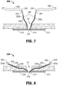
- hernia repair device 200 is positioned adjacent the tissue defect "D" to be repaired. At this point, sheaths 230 remain disposed about the barbed portions of filaments 220 and needles 224 to inhibit accidental injury or damage during handling of hernia repair device 200.
- mesh 210 is manipulated such that mesh 210 is insertable through the tissue defect "D" with minimal trauma to the surrounding tissue. More specifically, due to the resiliently flexible configuration of support members 212, 214, mesh 210 is able to be bent, curved, or otherwise manipulated to facilitate passage of mesh 210 through the tissue defect "D.” Once mesh 210 is positioned within the surgical site on a distal side of the tissue defect "D,” mesh 210 may be released to allow mesh 210 to return to its initial state. In this position, sheaths 230 remain disposed over needles 224 and barbs 238 to protect against inadvertent injury and/or damage from pointed tips 225 of needles 224 and/or barbs 238.
- mesh 210 extends completely across the tissue defect "D” such that first support member 212 surrounds the tissue defect "D” and such that filaments 220 extend proximally through the defect "D.” More specifically, filaments 220 extend proximally through second support member 214, which is positioned distal of and adjacent to the tissue defect "D.” Due to the fact that filaments 220 extend through second support member 214, which is centrally disposed about mesh 210, mesh 210 is automatically centered relative to the tissue defect "D” by grasping filaments 220 collectively and pulling proximally.
- mesh 210 is ready to be manipulated into position and secured to tissue to repair the tissue defect "D." Accordingly, sheaths 230 may be removed from filaments 220 to expose needle 224 and barbs 238 in preparation for securing mesh 210 to tissue.
- filaments 220 in order to properly position and securely engage mesh 210 to tissue, filaments 220, lead by needles 224, are advanced proximally through tissue (see Fig. 8 ). As mentioned above, pointed tips 225 of needles 224 facilitate the passage of filaments 220 through tissue. Filaments 220 are selectively pulled through tissue to orient mesh 210 in the desired position. More specifically, due to the barbed configuration of filaments 220, as filaments 220 are pulled through tissue, retreat of filaments 220 back through tissue is inhibited by the engagement of barbs 238 within tissue. Thus, filaments 220 may be used to incrementally position mesh 210 in a ratchet-like fashion, as will be described below.
- filament 220d which is secured to mesh 210 at the 9 o'clock position is pulled through tissue proximally and toward the 9 o'clock position to move the section of mesh 210 adjacent the 9 o'clock position into approximation with a distal surface of tissue, while the other sections of mesh 210 remain relatively stationary.
- mesh 210 is retained in position due to the engagement of barbs 238 within the tissue. In other words, barbs 238 inhibit mesh 210 from moving away from an approximated position relative to tissue.
- the clinician may pull filament 220d further proximally to engage more of barbs 238 of filament 220d within tissue, thereby retaining mesh 210 in a further approximated position.
- advancing filament 220d a relatively small distance engages additional barbs 238 within tissue, retaining filament 220d in position.
- the clinician may incrementally advance filament 220d (and the other filaments 220) to achieve the desired position of mesh 210 relative to tissue.
- the filaments 220 are advanced proximally through tissue in a general direction toward the attachment position of that filament 220 to mesh 210.
- filament 220d is advanced proximally and in the 9 o'clock direction through tissue.
- filament 220d which is secured to mesh 210 at the 3 o'clock position
- filament 220b which is secured to mesh 210 at the 3 o'clock position
- filaments 220d, 220b be advanced different distances through tissue, for example, in instances where tissue adjacent the defect "D" defines a varying thickness, or where the defect "D" defines an asymmetrical configuration.
- This incremental and independent adjustment may then be repeated for each of the remaining filaments 220, e.g., filaments 220a and 220c, similarly as described above.
- the clinician may independently and incrementally pull each filament 220 through tissue to secure mesh 210 in a desired position despite various anatomical considerations, e.g., varied tissue thicknesses, varied defect configurations and/or various different tissue surface contours.
- the proximal portions of filaments 220a-d including needles 224 may be cut, further stitched, or tied-off, leaving the remainder of filaments 220a-d fixedly secured within tissue. It is envisioned that the engagement of barbs 238 of filaments 220 within tissue in such a configuration as described above provides sufficient holding force to maintain mesh 210 in the desired position during the healing process of the tissue defect "D," obviating the need for additional fixation. However, additional fixation may be provided, if desired.
- Hernia repair devices of the present disclosure may include a mesh configured to extend across a tissue defect and a plurality of filaments coupled to the mesh in proximity of an outer periphery thereof and extending from a central portion of the mesh. Each filament includes a plurality of barbs disposed along at least a portion of the length thereof and has a needle disposed at a free end thereof.
- the mesh of the hernia repair device includes a first annular support member coupled thereto in proximity of the outer periphery thereof. In addition to the first annular support member, a second annular support member may be coupled to the mesh toward the central portion thereof.
- each filament may be coupled to the first annular support member and may extend radially inwardly along the mesh toward the second annular support member; each filament ultimately extending through an aperture defined by the second annular support member.
- the filaments may also be configured to provide radial structural support to the mesh, in addition to the support provided by the first and second annular support members.
- the filaments may also be equally-spaced about the mesh and relative to the first and second annular support members.
- Each filament may further include at least two support strands coupled thereto such that each filament is coupled to the mesh in at least two attachment positions.
- a removable protective sheath may be disposed about the needle of each of the filaments.
- the removable protective sheath of each filament is configured to extend along at least a portion of a length of the filament such that the removable protective sheath is disposed about barbs of the filament.
- the mesh may be resiliently deformable to facilitate insertion of the mesh through the tissue defect.
- the mesh may also be configured to conform to the anatomy of the tissue defect and surrounding tissue.
- the barbs of the filaments may be angled relative to the filaments such that each filament is configured to pass through tissue in a first direction but is inhibited from passing through tissue in a second, opposite direction.
Claims (12)
- Dispositif de réparation de hernie (100), comprenant :un treillis (110) configuré pour s'étendre sur un défaut de tissu (D) ; etune pluralité de filaments (120) s'étendant d'une partie centrale du treillis (110), chaque filament (120) comprenant une pluralité de barbillons (128) disposés le long d'au moins une partie de la longueur de celui-ci et ayant une aiguille (124) disposée à une extrémité libre (126) de celui-ci,caractérisé en ce que la pluralité de filaments (120) sont couplés au treillis (110) à proximité d'une périphérie extérieure de celui-ci.
- Dispositif de réparation de hernie selon la revendication 1, dans lequel le treillis inclut un premier élément de support annulaire (112) couplé à celui-ci à proximité de la périphérie extérieure de celui-ci.
- Dispositif de réparation de hernie selon la revendication 2, dans lequel le treillis inclut un deuxième élément de support annulaire (114) couplé à celui-ci vers la partie centrale de celui-ci.
- Dispositif de réparation de hernie selon la revendication 3, dans lequel chaque filament est couplé au premier élément de support annulaire et s'étend radialement vers l'intérieur le long du treillis vers le deuxième élément de support annulaire, chaque filament s'étendant à travers une ouverture (215) définie par le deuxième élément de support annulaire.
- Dispositif de réparation de hernie selon la revendication 4, dans lequel les filaments fournissent un support structurel radial au treillis.
- Dispositif de réparation de hernie selon la revendication 1, dans lequel les filaments sont sensiblement équidistants autour du treillis.
- Dispositif de réparation de hernie selon l'une quelconque des revendications précédentes, dans lequel chaque filament inclut au moins deux brins de support (321, 322) couplés à celui-ci de sorte que chaque filament est couplé au treillis dans au moins deux positions de fixation.
- Dispositif de réparation de hernie selon l'une quelconque des revendications 1 à 6, comprenant en outre une gaine de protection amovible (230, 330) disposée autour de l'aiguille de chacun des filaments.
- Dispositif de réparation de hernie selon la revendication 8, dans lequel la gaine de protection amovible de chaque filament est configurée pour s'étendre le long d'au moins une partie d'une longueur du filament de sorte que la gaine de protection amovible est disposée autour de barbillons du filament.
- Dispositif de réparation de hernie selon l'une quelconque des revendications 1 à 6, dans lequel le treillis est élastiquement déformable pour faciliter l'insertion du treillis à travers le défaut de tissu.
- Dispositif de réparation de hernie selon l'une quelconque des revendications 1 à 6, dans lequel le treillis est configuré pour s'adapter à l'anatomie du défaut de tissu et du tissu avoisinant.
- Dispositif de réparation de hernie selon l'une quelconque des revendications 1 à 6, dans lequel les barbillons forment un angle par rapport aux filaments de sorte que chaque filament est configuré pour passer à travers du tissu dans une première direction mais est empêché de passer à travers du tissu dans une deuxième direction opposée.
Applications Claiming Priority (2)
| Application Number | Priority Date | Filing Date | Title |
|---|---|---|---|
| US201161541645P | 2011-09-30 | 2011-09-30 | |
| PCT/US2012/058237 WO2013049787A1 (fr) | 2011-09-30 | 2012-10-01 | Dispositif et méthode de réparation de hernie |
Publications (3)
| Publication Number | Publication Date |
|---|---|
| EP2763600A1 EP2763600A1 (fr) | 2014-08-13 |
| EP2763600A4 EP2763600A4 (fr) | 2015-07-29 |
| EP2763600B1 true EP2763600B1 (fr) | 2019-01-23 |
Family
ID=47996493
Family Applications (1)
| Application Number | Title | Priority Date | Filing Date |
|---|---|---|---|
| EP12834873.7A Active EP2763600B1 (fr) | 2011-09-30 | 2012-10-01 | Dispositif de réparation de hernie |
Country Status (7)
| Country | Link |
|---|---|
| US (2) | US9492261B2 (fr) |
| EP (1) | EP2763600B1 (fr) |
| JP (1) | JP6088525B2 (fr) |
| CN (1) | CN103841904B (fr) |
| AU (1) | AU2012315583B2 (fr) |
| CA (1) | CA2849105C (fr) |
| WO (1) | WO2013049787A1 (fr) |
Families Citing this family (20)
| Publication number | Priority date | Publication date | Assignee | Title |
|---|---|---|---|---|
| US9492261B2 (en) * | 2011-09-30 | 2016-11-15 | Covidien Lp | Hernia repair device and method |
| JP6537520B2 (ja) * | 2014-03-06 | 2019-07-03 | シー・アール・バード・インコーポレーテッドC R Bard Incorporated | ヘルニア修復パッチ |
| US9981121B2 (en) | 2014-04-28 | 2018-05-29 | Medtronic, Inc. | Implantable medical devices, systems and components thereof |
| CA2959788C (fr) * | 2014-09-04 | 2022-04-19 | Duke University | Maille implantable et procede d'utilisation |
| US10172700B2 (en) | 2014-12-01 | 2019-01-08 | C.R. Bard, Inc. | Prosthesis for repairing a hernia defect |
| CN104799892A (zh) * | 2015-04-09 | 2015-07-29 | 平荧 | 网格化组织加固器 |
| US9713520B2 (en) * | 2015-06-29 | 2017-07-25 | Ethicon, Inc. | Skirted tissue repair implant having position indication feature |
| USD841809S1 (en) * | 2015-07-02 | 2019-02-26 | C.R. Bard, Inc. | Implant |
| US9888997B2 (en) * | 2015-07-20 | 2018-02-13 | Arthrex, Inc. | Soft anchor assembly with barbed flexible strand and techniques for use |
| ES2847758T3 (es) | 2015-12-28 | 2021-08-03 | Bard Inc C R | Prótesis para reparar un defecto de hernia |
| CA3014775C (fr) * | 2016-03-10 | 2023-07-25 | Exeger Operations Ab | Cellule solaire comprenant des grains d'un materiau semi-conducteur dope et procede de fabrication de la cellule solaire |
| KR101825736B1 (ko) * | 2017-06-15 | 2018-02-05 | 심재완 | 조직 수복용 메쉬 어셈블리 |
| US10624729B2 (en) | 2017-10-12 | 2020-04-21 | C.R. Bard, Inc. | Repair prosthetic curl mitigation |
| US10842603B1 (en) * | 2017-10-16 | 2020-11-24 | David Lee Street | Sutureless ventral hernia meshing system and method of fixation |
| CN108113716A (zh) * | 2017-12-29 | 2018-06-05 | 谢永伟 | 疝封堵装置 |
| US20190231481A1 (en) * | 2018-01-31 | 2019-08-01 | Won Moon | Elastic orthodontic appliance |
| US10413386B2 (en) | 2018-01-31 | 2019-09-17 | Won Moon | Hybrid orthodontic appliance |
| US10485635B2 (en) | 2018-01-31 | 2019-11-26 | Won Moon | Orthodontic appliance |
| WO2019168926A1 (fr) * | 2018-02-28 | 2019-09-06 | BandGrip, Inc. | Ensemble de fermeture de plaie sous-cutanée et procédé d'utilisation |
| US10786647B2 (en) * | 2018-04-26 | 2020-09-29 | Thomas Umbach | Hiatal hernia treatment |
Family Cites Families (43)
| Publication number | Priority date | Publication date | Assignee | Title |
|---|---|---|---|---|
| US2671444A (en) * | 1951-12-08 | 1954-03-09 | Jr Benjamin F Pease | Nonmetallic mesh surgical insert for hernia repair |
| US4865026A (en) * | 1987-04-23 | 1989-09-12 | Barrett David M | Sealing wound closure device |
| US5116357A (en) * | 1990-10-11 | 1992-05-26 | Eberbach Mark A | Hernia plug and introducer apparatus |
| JPH08196538A (ja) * | 1994-09-26 | 1996-08-06 | Ethicon Inc | エラストマー部材を有する外科用の組織付着器具および該組織へ外科用のメッシュを張り付ける方法 |
| US5634931A (en) * | 1994-09-29 | 1997-06-03 | Surgical Sense, Inc. | Hernia mesh patches and methods of their use |
| US5879366A (en) * | 1996-12-20 | 1999-03-09 | W.L. Gore & Associates, Inc. | Self-expanding defect closure device and method of making and using |
| US6669735B1 (en) * | 1998-07-31 | 2003-12-30 | Davol, Inc. | Prosthesis for surgical treatment of hernia |
| US6436030B2 (en) * | 2000-01-31 | 2002-08-20 | Om P. Rehil | Hiatal hernia repair patch and method for using the same |
| US6270517B1 (en) | 2000-02-04 | 2001-08-07 | Gregory R. Brotz | Suture assembly and method |
| IT1318499B1 (it) * | 2000-05-05 | 2003-08-25 | Angiologica B M S R L | Rete anatomica a doppio strato per chirurgia. |
| US20020103494A1 (en) * | 2001-01-31 | 2002-08-01 | Pacey John Allen | Percutaneous cannula delvery system for hernia patch |
| GB0108088D0 (en) * | 2001-03-30 | 2001-05-23 | Browning Healthcare Ltd | Surgical implant |
| US6790213B2 (en) * | 2002-01-07 | 2004-09-14 | C.R. Bard, Inc. | Implantable prosthesis |
| US6736823B2 (en) * | 2002-05-10 | 2004-05-18 | C.R. Bard, Inc. | Prosthetic repair fabric |
| DK174649B1 (da) * | 2002-07-25 | 2003-08-04 | Nortec Holding S A | Implantat |
| US7101381B2 (en) | 2002-08-02 | 2006-09-05 | C.R. Bard, Inc. | Implantable prosthesis |
| US20040073257A1 (en) * | 2002-10-09 | 2004-04-15 | Spitz Gregory A. | Methods and apparatus for the repair of hernias |
| US7021316B2 (en) | 2003-08-07 | 2006-04-04 | Tools For Surgery, Llc | Device and method for tacking a prosthetic screen |
| DE102004020469A1 (de) * | 2004-04-26 | 2005-11-10 | Gfe Medizintechnik Gmbh | Flächiges Netzimplantat zur Hernienversorgung |
| US20100189764A1 (en) * | 2005-03-22 | 2010-07-29 | Jonathan Thomas | Bioactive mesh |
| CA2665209C (fr) * | 2006-10-03 | 2016-01-05 | Alure Medical, Inc. | Support tissulaire tres peu invasif |
| US7828854B2 (en) * | 2006-10-31 | 2010-11-09 | Ethicon, Inc. | Implantable repair device |
| AU2008204786A1 (en) * | 2007-01-10 | 2008-07-17 | Cook Biotech Incorporated | Implantable devices useful for reinforcing a surgically created stoma |
| FR2914178B1 (fr) | 2007-03-27 | 2010-05-14 | Cie De Rech En Composants Impl | Prothese implantable de renfort avec des moyens de fixation |
| US8500759B2 (en) * | 2007-09-26 | 2013-08-06 | Ethicon, Inc. | Hernia mesh support device |
| EP2231064A4 (fr) | 2007-12-13 | 2014-04-16 | Insightra Medical | Méthodes et appareil pour le traitement de la hernie de paroi ventrale |
| US20090228021A1 (en) * | 2008-03-06 | 2009-09-10 | Leung Jeffrey C | Matrix material |
| US9358002B2 (en) * | 2008-04-01 | 2016-06-07 | Covidien Lp | Anchoring device |
| US9242026B2 (en) * | 2008-06-27 | 2016-01-26 | Sofradim Production | Biosynthetic implant for soft tissue repair |
| AU2009319965B2 (en) * | 2008-11-03 | 2014-11-06 | Ethicon Llc | Length of self-retaining suture and method and device for using the same |
| US20100241145A1 (en) * | 2009-03-20 | 2010-09-23 | Douglas Wesley Cook | Hernia mesh system with removable memory wire |
| US9011487B2 (en) * | 2009-08-27 | 2015-04-21 | Ethicon, Inc. | Barbed sutures having pledget stoppers and methods therefor |
| US8579922B2 (en) * | 2009-10-05 | 2013-11-12 | Covidien Lp | Method of suture identification and mesh marking for orienting and locating a mesh during hernia repair |
| US9398943B2 (en) * | 2009-11-30 | 2016-07-26 | Covidien Lp | Ventral hernia repair with barbed suture |
| ES2875830T3 (es) | 2010-05-11 | 2021-11-11 | Aesculap Ag | Uso de un hilo de filamento continuo con una pluralidad de púas para la producción de suturas |
| WO2012021600A1 (fr) * | 2010-08-10 | 2012-02-16 | Tyco Healthcare Group Lp | Dispositifs implantables à barbules |
| CA2853562C (fr) * | 2011-09-30 | 2019-04-09 | Covidien Lp | Dispositif de reparation des hernies et procede correspondant |
| US9572649B2 (en) * | 2011-09-30 | 2017-02-21 | Covidien Lp | Implantable prosthesis for repairing or reinforcing an anatomical defect |
| US9492261B2 (en) * | 2011-09-30 | 2016-11-15 | Covidien Lp | Hernia repair device and method |
| FR2988289B1 (fr) * | 2012-03-22 | 2014-04-04 | Sofradim Production | Guide pour fixation d’une prothese |
| US8945235B2 (en) * | 2012-03-27 | 2015-02-03 | Atrium Medical Corporation | Removable deployment device, system, and method for implantable prostheses |
| EP2887886B1 (fr) * | 2012-08-23 | 2020-04-22 | Covidien LP | Dispositif de fixation de tissu |
| US9872751B2 (en) * | 2013-03-11 | 2018-01-23 | Boston Scientific Scimed, Inc. | Implantable medical device and methods of delivering the implantable medical device |
-
2012
- 2012-10-01 US US14/345,792 patent/US9492261B2/en active Active
- 2012-10-01 JP JP2014533465A patent/JP6088525B2/ja not_active Expired - Fee Related
- 2012-10-01 AU AU2012315583A patent/AU2012315583B2/en not_active Ceased
- 2012-10-01 EP EP12834873.7A patent/EP2763600B1/fr active Active
- 2012-10-01 CN CN201280047937.3A patent/CN103841904B/zh active Active
- 2012-10-01 WO PCT/US2012/058237 patent/WO2013049787A1/fr active Application Filing
- 2012-10-01 CA CA2849105A patent/CA2849105C/fr active Active
-
2016
- 2016-09-26 US US15/275,627 patent/US10258449B2/en active Active
Non-Patent Citations (1)
| Title |
|---|
| None * |
Also Published As
| Publication number | Publication date |
|---|---|
| CN103841904A (zh) | 2014-06-04 |
| CN103841904B (zh) | 2018-01-09 |
| CA2849105C (fr) | 2019-11-05 |
| CA2849105A1 (fr) | 2013-04-04 |
| US9492261B2 (en) | 2016-11-15 |
| US20150157437A1 (en) | 2015-06-11 |
| US10258449B2 (en) | 2019-04-16 |
| WO2013049787A1 (fr) | 2013-04-04 |
| US20170007387A1 (en) | 2017-01-12 |
| JP6088525B2 (ja) | 2017-03-01 |
| JP2014531938A (ja) | 2014-12-04 |
| EP2763600A4 (fr) | 2015-07-29 |
| EP2763600A1 (fr) | 2014-08-13 |
| AU2012315583A1 (en) | 2014-02-13 |
| AU2012315583B2 (en) | 2017-05-11 |
Similar Documents
| Publication | Publication Date | Title |
|---|---|---|
| US10258449B2 (en) | Hernia repair device and method | |
| JP6396402B2 (ja) | 自己保持可変ループ縫合材 | |
| CA2746211C (fr) | Dispositif d'agrafage retractable | |
| JP5694328B2 (ja) | 綿撒糸ストッパを有する有棘縫合糸とそのための方法 | |
| US20170086806A1 (en) | Vascular closure methods and apparatuses | |
| EP2760342B1 (fr) | Dispositif de réparation des hernies | |
| US9642690B2 (en) | Suture loaded umbilical mesh | |
| US20150351768A1 (en) | Connector |
Legal Events
| Date | Code | Title | Description |
|---|---|---|---|
| PUAI | Public reference made under article 153(3) epc to a published international application that has entered the european phase |
Free format text: ORIGINAL CODE: 0009012 |
|
| 17P | Request for examination filed |
Effective date: 20140429 |
|
| AK | Designated contracting states |
Kind code of ref document: A1 Designated state(s): AL AT BE BG CH CY CZ DE DK EE ES FI FR GB GR HR HU IE IS IT LI LT LU LV MC MK MT NL NO PL PT RO RS SE SI SK SM TR |
|
| DAX | Request for extension of the european patent (deleted) | ||
| RA4 | Supplementary search report drawn up and despatched (corrected) |
Effective date: 20150625 |
|
| RIC1 | Information provided on ipc code assigned before grant |
Ipc: A61B 17/08 20060101AFI20150619BHEP |
|
| REG | Reference to a national code |
Ref country code: DE Ref legal event code: R079 Ref document number: 602012056318 Country of ref document: DE Free format text: PREVIOUS MAIN CLASS: A61B0017080000 Ipc: A61F0002000000 |
|
| GRAP | Despatch of communication of intention to grant a patent |
Free format text: ORIGINAL CODE: EPIDOSNIGR1 |
|
| STAA | Information on the status of an ep patent application or granted ep patent |
Free format text: STATUS: GRANT OF PATENT IS INTENDED |
|
| RIC1 | Information provided on ipc code assigned before grant |
Ipc: A61B 17/04 20060101ALI20180725BHEP Ipc: A61F 2/00 20060101AFI20180725BHEP Ipc: A61B 17/06 20060101ALI20180725BHEP |
|
| INTG | Intention to grant announced |
Effective date: 20180817 |
|
| GRAS | Grant fee paid |
Free format text: ORIGINAL CODE: EPIDOSNIGR3 |
|
| GRAA | (expected) grant |
Free format text: ORIGINAL CODE: 0009210 |
|
| STAA | Information on the status of an ep patent application or granted ep patent |
Free format text: STATUS: THE PATENT HAS BEEN GRANTED |
|
| AK | Designated contracting states |
Kind code of ref document: B1 Designated state(s): AL AT BE BG CH CY CZ DE DK EE ES FI FR GB GR HR HU IE IS IT LI LT LU LV MC MK MT NL NO PL PT RO RS SE SI SK SM TR |
|
| REG | Reference to a national code |
Ref country code: GB Ref legal event code: FG4D |
|
| REG | Reference to a national code |
Ref country code: CH Ref legal event code: EP |
|
| REG | Reference to a national code |
Ref country code: AT Ref legal event code: REF Ref document number: 1090865 Country of ref document: AT Kind code of ref document: T Effective date: 20190215 |
|
| REG | Reference to a national code |
Ref country code: IE Ref legal event code: FG4D |
|
| REG | Reference to a national code |
Ref country code: DE Ref legal event code: R096 Ref document number: 602012056318 Country of ref document: DE |
|
| REG | Reference to a national code |
Ref country code: NL Ref legal event code: MP Effective date: 20190123 |
|
| PG25 | Lapsed in a contracting state [announced via postgrant information from national office to epo] |
Ref country code: NL Free format text: LAPSE BECAUSE OF FAILURE TO SUBMIT A TRANSLATION OF THE DESCRIPTION OR TO PAY THE FEE WITHIN THE PRESCRIBED TIME-LIMIT Effective date: 20190123 |
|
| PG25 | Lapsed in a contracting state [announced via postgrant information from national office to epo] |
Ref country code: NO Free format text: LAPSE BECAUSE OF FAILURE TO SUBMIT A TRANSLATION OF THE DESCRIPTION OR TO PAY THE FEE WITHIN THE PRESCRIBED TIME-LIMIT Effective date: 20190423 Ref country code: FI Free format text: LAPSE BECAUSE OF FAILURE TO SUBMIT A TRANSLATION OF THE DESCRIPTION OR TO PAY THE FEE WITHIN THE PRESCRIBED TIME-LIMIT Effective date: 20190123 Ref country code: PL Free format text: LAPSE BECAUSE OF FAILURE TO SUBMIT A TRANSLATION OF THE DESCRIPTION OR TO PAY THE FEE WITHIN THE PRESCRIBED TIME-LIMIT Effective date: 20190123 Ref country code: SE Free format text: LAPSE BECAUSE OF FAILURE TO SUBMIT A TRANSLATION OF THE DESCRIPTION OR TO PAY THE FEE WITHIN THE PRESCRIBED TIME-LIMIT Effective date: 20190123 Ref country code: PT Free format text: LAPSE BECAUSE OF FAILURE TO SUBMIT A TRANSLATION OF THE DESCRIPTION OR TO PAY THE FEE WITHIN THE PRESCRIBED TIME-LIMIT Effective date: 20190523 Ref country code: ES Free format text: LAPSE BECAUSE OF FAILURE TO SUBMIT A TRANSLATION OF THE DESCRIPTION OR TO PAY THE FEE WITHIN THE PRESCRIBED TIME-LIMIT Effective date: 20190123 Ref country code: LT Free format text: LAPSE BECAUSE OF FAILURE TO SUBMIT A TRANSLATION OF THE DESCRIPTION OR TO PAY THE FEE WITHIN THE PRESCRIBED TIME-LIMIT Effective date: 20190123 |
|
| REG | Reference to a national code |
Ref country code: AT Ref legal event code: MK05 Ref document number: 1090865 Country of ref document: AT Kind code of ref document: T Effective date: 20190123 |
|
| PG25 | Lapsed in a contracting state [announced via postgrant information from national office to epo] |
Ref country code: BG Free format text: LAPSE BECAUSE OF FAILURE TO SUBMIT A TRANSLATION OF THE DESCRIPTION OR TO PAY THE FEE WITHIN THE PRESCRIBED TIME-LIMIT Effective date: 20190423 Ref country code: GR Free format text: LAPSE BECAUSE OF FAILURE TO SUBMIT A TRANSLATION OF THE DESCRIPTION OR TO PAY THE FEE WITHIN THE PRESCRIBED TIME-LIMIT Effective date: 20190424 Ref country code: HR Free format text: LAPSE BECAUSE OF FAILURE TO SUBMIT A TRANSLATION OF THE DESCRIPTION OR TO PAY THE FEE WITHIN THE PRESCRIBED TIME-LIMIT Effective date: 20190123 Ref country code: RS Free format text: LAPSE BECAUSE OF FAILURE TO SUBMIT A TRANSLATION OF THE DESCRIPTION OR TO PAY THE FEE WITHIN THE PRESCRIBED TIME-LIMIT Effective date: 20190123 Ref country code: LV Free format text: LAPSE BECAUSE OF FAILURE TO SUBMIT A TRANSLATION OF THE DESCRIPTION OR TO PAY THE FEE WITHIN THE PRESCRIBED TIME-LIMIT Effective date: 20190123 Ref country code: IS Free format text: LAPSE BECAUSE OF FAILURE TO SUBMIT A TRANSLATION OF THE DESCRIPTION OR TO PAY THE FEE WITHIN THE PRESCRIBED TIME-LIMIT Effective date: 20190523 |
|
| REG | Reference to a national code |
Ref country code: DE Ref legal event code: R097 Ref document number: 602012056318 Country of ref document: DE |
|
| PG25 | Lapsed in a contracting state [announced via postgrant information from national office to epo] |
Ref country code: AL Free format text: LAPSE BECAUSE OF FAILURE TO SUBMIT A TRANSLATION OF THE DESCRIPTION OR TO PAY THE FEE WITHIN THE PRESCRIBED TIME-LIMIT Effective date: 20190123 Ref country code: EE Free format text: LAPSE BECAUSE OF FAILURE TO SUBMIT A TRANSLATION OF THE DESCRIPTION OR TO PAY THE FEE WITHIN THE PRESCRIBED TIME-LIMIT Effective date: 20190123 Ref country code: DK Free format text: LAPSE BECAUSE OF FAILURE TO SUBMIT A TRANSLATION OF THE DESCRIPTION OR TO PAY THE FEE WITHIN THE PRESCRIBED TIME-LIMIT Effective date: 20190123 Ref country code: IT Free format text: LAPSE BECAUSE OF FAILURE TO SUBMIT A TRANSLATION OF THE DESCRIPTION OR TO PAY THE FEE WITHIN THE PRESCRIBED TIME-LIMIT Effective date: 20190123 Ref country code: CZ Free format text: LAPSE BECAUSE OF FAILURE TO SUBMIT A TRANSLATION OF THE DESCRIPTION OR TO PAY THE FEE WITHIN THE PRESCRIBED TIME-LIMIT Effective date: 20190123 Ref country code: SK Free format text: LAPSE BECAUSE OF FAILURE TO SUBMIT A TRANSLATION OF THE DESCRIPTION OR TO PAY THE FEE WITHIN THE PRESCRIBED TIME-LIMIT Effective date: 20190123 Ref country code: RO Free format text: LAPSE BECAUSE OF FAILURE TO SUBMIT A TRANSLATION OF THE DESCRIPTION OR TO PAY THE FEE WITHIN THE PRESCRIBED TIME-LIMIT Effective date: 20190123 |
|
| PG25 | Lapsed in a contracting state [announced via postgrant information from national office to epo] |
Ref country code: SM Free format text: LAPSE BECAUSE OF FAILURE TO SUBMIT A TRANSLATION OF THE DESCRIPTION OR TO PAY THE FEE WITHIN THE PRESCRIBED TIME-LIMIT Effective date: 20190123 |
|
| PLBE | No opposition filed within time limit |
Free format text: ORIGINAL CODE: 0009261 |
|
| STAA | Information on the status of an ep patent application or granted ep patent |
Free format text: STATUS: NO OPPOSITION FILED WITHIN TIME LIMIT |
|
| PG25 | Lapsed in a contracting state [announced via postgrant information from national office to epo] |
Ref country code: AT Free format text: LAPSE BECAUSE OF FAILURE TO SUBMIT A TRANSLATION OF THE DESCRIPTION OR TO PAY THE FEE WITHIN THE PRESCRIBED TIME-LIMIT Effective date: 20190123 |
|
| 26N | No opposition filed |
Effective date: 20191024 |
|
| PG25 | Lapsed in a contracting state [announced via postgrant information from national office to epo] |
Ref country code: SI Free format text: LAPSE BECAUSE OF FAILURE TO SUBMIT A TRANSLATION OF THE DESCRIPTION OR TO PAY THE FEE WITHIN THE PRESCRIBED TIME-LIMIT Effective date: 20190123 |
|
| PG25 | Lapsed in a contracting state [announced via postgrant information from national office to epo] |
Ref country code: TR Free format text: LAPSE BECAUSE OF FAILURE TO SUBMIT A TRANSLATION OF THE DESCRIPTION OR TO PAY THE FEE WITHIN THE PRESCRIBED TIME-LIMIT Effective date: 20190123 |
|
| PG25 | Lapsed in a contracting state [announced via postgrant information from national office to epo] |
Ref country code: MC Free format text: LAPSE BECAUSE OF FAILURE TO SUBMIT A TRANSLATION OF THE DESCRIPTION OR TO PAY THE FEE WITHIN THE PRESCRIBED TIME-LIMIT Effective date: 20190123 |
|
| REG | Reference to a national code |
Ref country code: CH Ref legal event code: PL |
|
| PG25 | Lapsed in a contracting state [announced via postgrant information from national office to epo] |
Ref country code: LI Free format text: LAPSE BECAUSE OF NON-PAYMENT OF DUE FEES Effective date: 20191031 Ref country code: CH Free format text: LAPSE BECAUSE OF NON-PAYMENT OF DUE FEES Effective date: 20191031 Ref country code: LU Free format text: LAPSE BECAUSE OF NON-PAYMENT OF DUE FEES Effective date: 20191001 |
|
| REG | Reference to a national code |
Ref country code: BE Ref legal event code: MM Effective date: 20191031 |
|
| PG25 | Lapsed in a contracting state [announced via postgrant information from national office to epo] |
Ref country code: BE Free format text: LAPSE BECAUSE OF NON-PAYMENT OF DUE FEES Effective date: 20191031 |
|
| PGFP | Annual fee paid to national office [announced via postgrant information from national office to epo] |
Ref country code: GB Payment date: 20200921 Year of fee payment: 9 |
|
| PG25 | Lapsed in a contracting state [announced via postgrant information from national office to epo] |
Ref country code: CY Free format text: LAPSE BECAUSE OF FAILURE TO SUBMIT A TRANSLATION OF THE DESCRIPTION OR TO PAY THE FEE WITHIN THE PRESCRIBED TIME-LIMIT Effective date: 20190123 |
|
| PG25 | Lapsed in a contracting state [announced via postgrant information from national office to epo] |
Ref country code: HU Free format text: LAPSE BECAUSE OF FAILURE TO SUBMIT A TRANSLATION OF THE DESCRIPTION OR TO PAY THE FEE WITHIN THE PRESCRIBED TIME-LIMIT; INVALID AB INITIO Effective date: 20121001 Ref country code: MT Free format text: LAPSE BECAUSE OF FAILURE TO SUBMIT A TRANSLATION OF THE DESCRIPTION OR TO PAY THE FEE WITHIN THE PRESCRIBED TIME-LIMIT Effective date: 20190123 |
|
| GBPC | Gb: european patent ceased through non-payment of renewal fee |
Effective date: 20211001 |
|
| PG25 | Lapsed in a contracting state [announced via postgrant information from national office to epo] |
Ref country code: MK Free format text: LAPSE BECAUSE OF FAILURE TO SUBMIT A TRANSLATION OF THE DESCRIPTION OR TO PAY THE FEE WITHIN THE PRESCRIBED TIME-LIMIT Effective date: 20190123 |
|
| PG25 | Lapsed in a contracting state [announced via postgrant information from national office to epo] |
Ref country code: GB Free format text: LAPSE BECAUSE OF NON-PAYMENT OF DUE FEES Effective date: 20211001 |
|
| PGFP | Annual fee paid to national office [announced via postgrant information from national office to epo] |
Ref country code: IE Payment date: 20220921 Year of fee payment: 11 |
|
| PGFP | Annual fee paid to national office [announced via postgrant information from national office to epo] |
Ref country code: FR Payment date: 20230920 Year of fee payment: 12 |
|
| PGFP | Annual fee paid to national office [announced via postgrant information from national office to epo] |
Ref country code: DE Payment date: 20230920 Year of fee payment: 12 |