EP2763243B1 - Verbindungselement und Verfahren zur Herstellung eines Verbindungselements - Google Patents
Verbindungselement und Verfahren zur Herstellung eines Verbindungselements Download PDFInfo
- Publication number
- EP2763243B1 EP2763243B1 EP13153250.9A EP13153250A EP2763243B1 EP 2763243 B1 EP2763243 B1 EP 2763243B1 EP 13153250 A EP13153250 A EP 13153250A EP 2763243 B1 EP2763243 B1 EP 2763243B1
- Authority
- EP
- European Patent Office
- Prior art keywords
- connecting element
- layers
- grounding
- layer
- electrically conductive
- Prior art date
- Legal status (The legal status is an assumption and is not a legal conclusion. Google has not performed a legal analysis and makes no representation as to the accuracy of the status listed.)
- Active
Links
Images
Classifications
-
- H—ELECTRICITY
- H01—ELECTRIC ELEMENTS
- H01R—ELECTRICALLY-CONDUCTIVE CONNECTIONS; STRUCTURAL ASSOCIATIONS OF A PLURALITY OF MUTUALLY-INSULATED ELECTRICAL CONNECTING ELEMENTS; COUPLING DEVICES; CURRENT COLLECTORS
- H01R4/00—Electrically-conductive connections between two or more conductive members in direct contact, i.e. touching one another; Means for effecting or maintaining such contact; Electrically-conductive connections having two or more spaced connecting locations for conductors and using contact members penetrating insulation
- H01R4/58—Electrically-conductive connections between two or more conductive members in direct contact, i.e. touching one another; Means for effecting or maintaining such contact; Electrically-conductive connections having two or more spaced connecting locations for conductors and using contact members penetrating insulation characterised by the form or material of the contacting members
- H01R4/62—Connections between conductors of different materials; Connections between or with aluminium or steel-core aluminium conductors
-
- H—ELECTRICITY
- H01—ELECTRIC ELEMENTS
- H01R—ELECTRICALLY-CONDUCTIVE CONNECTIONS; STRUCTURAL ASSOCIATIONS OF A PLURALITY OF MUTUALLY-INSULATED ELECTRICAL CONNECTING ELEMENTS; COUPLING DEVICES; CURRENT COLLECTORS
- H01R13/00—Details of coupling devices of the kinds covered by groups H01R12/70 or H01R24/00 - H01R33/00
- H01R13/02—Contact members
- H01R13/03—Contact members characterised by the material, e.g. plating, or coating materials
-
- H—ELECTRICITY
- H01—ELECTRIC ELEMENTS
- H01R—ELECTRICALLY-CONDUCTIVE CONNECTIONS; STRUCTURAL ASSOCIATIONS OF A PLURALITY OF MUTUALLY-INSULATED ELECTRICAL CONNECTING ELEMENTS; COUPLING DEVICES; CURRENT COLLECTORS
- H01R35/00—Flexible or turnable line connectors, i.e. the rotation angle being limited
- H01R35/02—Flexible line connectors without frictional contact members
-
- H—ELECTRICITY
- H01—ELECTRIC ELEMENTS
- H01R—ELECTRICALLY-CONDUCTIVE CONNECTIONS; STRUCTURAL ASSOCIATIONS OF A PLURALITY OF MUTUALLY-INSULATED ELECTRICAL CONNECTING ELEMENTS; COUPLING DEVICES; CURRENT COLLECTORS
- H01R4/00—Electrically-conductive connections between two or more conductive members in direct contact, i.e. touching one another; Means for effecting or maintaining such contact; Electrically-conductive connections having two or more spaced connecting locations for conductors and using contact members penetrating insulation
- H01R4/58—Electrically-conductive connections between two or more conductive members in direct contact, i.e. touching one another; Means for effecting or maintaining such contact; Electrically-conductive connections having two or more spaced connecting locations for conductors and using contact members penetrating insulation characterised by the form or material of the contacting members
- H01R4/64—Connections between or with conductive parts having primarily a non-electric function, e.g. frame, casing, rail
-
- H—ELECTRICITY
- H01—ELECTRIC ELEMENTS
- H01R—ELECTRICALLY-CONDUCTIVE CONNECTIONS; STRUCTURAL ASSOCIATIONS OF A PLURALITY OF MUTUALLY-INSULATED ELECTRICAL CONNECTING ELEMENTS; COUPLING DEVICES; CURRENT COLLECTORS
- H01R4/00—Electrically-conductive connections between two or more conductive members in direct contact, i.e. touching one another; Means for effecting or maintaining such contact; Electrically-conductive connections having two or more spaced connecting locations for conductors and using contact members penetrating insulation
- H01R4/28—Clamped connections, spring connections
- H01R4/30—Clamped connections, spring connections utilising a screw or nut clamping member
-
- H—ELECTRICITY
- H01—ELECTRIC ELEMENTS
- H01R—ELECTRICALLY-CONDUCTIVE CONNECTIONS; STRUCTURAL ASSOCIATIONS OF A PLURALITY OF MUTUALLY-INSULATED ELECTRICAL CONNECTING ELEMENTS; COUPLING DEVICES; CURRENT COLLECTORS
- H01R4/00—Electrically-conductive connections between two or more conductive members in direct contact, i.e. touching one another; Means for effecting or maintaining such contact; Electrically-conductive connections having two or more spaced connecting locations for conductors and using contact members penetrating insulation
- H01R4/28—Clamped connections, spring connections
- H01R4/38—Clamped connections, spring connections utilising a clamping member acted on by screw or nut
-
- H—ELECTRICITY
- H01—ELECTRIC ELEMENTS
- H01R—ELECTRICALLY-CONDUCTIVE CONNECTIONS; STRUCTURAL ASSOCIATIONS OF A PLURALITY OF MUTUALLY-INSULATED ELECTRICAL CONNECTING ELEMENTS; COUPLING DEVICES; CURRENT COLLECTORS
- H01R4/00—Electrically-conductive connections between two or more conductive members in direct contact, i.e. touching one another; Means for effecting or maintaining such contact; Electrically-conductive connections having two or more spaced connecting locations for conductors and using contact members penetrating insulation
- H01R4/58—Electrically-conductive connections between two or more conductive members in direct contact, i.e. touching one another; Means for effecting or maintaining such contact; Electrically-conductive connections having two or more spaced connecting locations for conductors and using contact members penetrating insulation characterised by the form or material of the contacting members
- H01R4/66—Connections with the terrestrial mass, e.g. earth plate, earth pin
-
- H—ELECTRICITY
- H01—ELECTRIC ELEMENTS
- H01R—ELECTRICALLY-CONDUCTIVE CONNECTIONS; STRUCTURAL ASSOCIATIONS OF A PLURALITY OF MUTUALLY-INSULATED ELECTRICAL CONNECTING ELEMENTS; COUPLING DEVICES; CURRENT COLLECTORS
- H01R9/00—Structural associations of a plurality of mutually-insulated electrical connecting elements, e.g. terminal strips or terminal blocks; Terminals or binding posts mounted upon a base or in a case; Bases therefor
- H01R9/03—Connectors arranged to contact a plurality of the conductors of a multiconductor cable, e.g. tapping connections
- H01R9/05—Connectors arranged to contact a plurality of the conductors of a multiconductor cable, e.g. tapping connections for coaxial cables
- H01R9/0512—Connections to an additional grounding conductor
Definitions
- the present invention relates to a connecting element for establishing an electrically conductive connection between two further elements.
- the invention further relates to a method of manufacturing such connecting element.
- Connecting elements of the aforementioned type are used as part of grounding kits for connecting a coaxial cable or a cable of another type in outdoor applications to a ground potential.
- grounding kits may be used for grounding cables of cellular base stations and broadcast systems and the like. Such grounding is necessary to protect people and equipment from damages in case of lightning strikes and to prevent electrical potential differences to build up between the cable and other devices.
- grounding kits and their connection elements comprise crimp joints between different electrical conductors which are to be connected with each other.
- These crimp joints are comparatively complex to manufacture and do not provide for a reliable mechanical and electrical connection of elements under certain operational conditions.
- US 2011/0076861 A1 discloses a laminar electrical connector, wherein a stack of superimposed metal strips are joined into a unified body both structurally and electrically.
- US 6,422,900 B1 discloses a connector assembly for coupling a continuous length of coaxial cable to a bulkhead.
- WO 2007/049834 A1 discloses a grounding wire which is surrounded by a stainless steel covering pipe.
- this object is achieved by the feature combination according to claim 1.
- the three or more layers of the connecting element are arranged in a stacked configuration such that a sandwich-type assembly is obtained.
- At least one layer of the connecting element may comprise a plurality of materials.
- at least one layer of the connecting element is made of a specific material, i.e. does not comprise substantial portions of further materials.
- At least one layer is comprised of a portion of sheet metal made of the respective material.
- at least one layer may be made of material other than sheet metal, as long as sufficient electrical conductivity is ensured.
- At least one layer or the sheet metal which represents said layer, respectively comprises a substantially rectangular shape wherein a width and a length of said layer are large compared to a layer thickness of the respective layer.
- L defines a length
- W defines a width of the basically rectangular portion of sheet metal defining a specific layer
- the thickness d of said layer is defined by d ⁇ L/10 and/or d ⁇ W/5.
- length L and width W may comprise a ratio of L / W > 10.
- the stacked configuration of at least three layers of the connecting element according to an embodiment is mechanically flexible as opposed to monolithic connecting elements found in prior art, which facilitates mounting in the field and avoids additional machining for adapting the connecting element to different target systems.
- a particular advantage of the connecting element according to the embodiments is the fact that at least three layers comprise different material which enables to combine materials with different properties, preferably regarding mechanical stability, in particular tensile strength, and regarding electrical conductivity.
- connecting elements may be provided which comprise a very good (i.e., high) electrical conductivity and which are thus ideally suited for grounding purposes or for establishing other electrical connections (i.e., other than to ground potential).
- the connecting elements according to the embodiments comprise a comparatively high tensile strength contributing to a mechanically robust configuration.
- maximum tensile strengths for the connecting element may be attained which are much higher than the tensile strength of conventional connecting elements comprising crimp joints.
- At least one layer comprises copper and/or aluminium, whereby a low electric, i.e. Ohmic, resistance is attained.
- a whole, i.e. complete, layer of the connecting element may be made of a specific material such as e.g. copper or aluminium.
- a layer in the sense of the embodiments may also comprise different components such as sub-layers or the like, i.e. a layer in the sense of the embodiments is not restricted to a monolithic assembly as such.
- At least one layer comprises a material other than copper or aluminium, preferably a material with a higher tensile strength than that of copper or aluminium.
- at least one layer of the connecting element comprises stainless steel.
- stainless steel comprises a lower electrical conductivity in comparison to copper or aluminium, however it comprises an increased tensile strength.
- a combination of aluminium and stainless steel (or copper and stainless steel) is particularly preferred, because it offers both a good electrical conductivity and a good maximum tensile strength thus withstanding high tensile forces.
- a plurality of layers of the connecting element may be made of the same material or may comprise the same material. For example, it is possible to provide a connecting element which comprises a first number of layers made of aluminium, and at least one further layer which is made of a different material, for example stainless steel or the like.
- the connecting element in order to avoid contact corrosion between adjacent conductors such as the connecting element and e.g. a grounding element (for example a foundation earth electrode) the connecting element is to be connected to, it may be advantageous to place e.g. stainless steel material in the outer layers of the stack configuration of the connecting element, and to place less noble materials in the inner layers of the connecting element.
- the outer layers of the connecting element could be made of stainless steel, whereas the inner layers could be made of copper or aluminium.
- the outer layers may even comprise a noble metal or at least a thin (i.e. galvanized) layer of noble metal such as silver to prevent contact corrosion.
- At least two layers have a same layer thickness, which advantageously enables to provide a large number of identical components for assembling a connecting element according to the embodiments.
- at least two layers have different layer thickness which provides further degrees of freedom regarding the construction of the connecting element.
- each group comprises layers of identical thickness, and wherein different groups are associated with different layer thicknesses.
- At least one layer of the connecting element is at least partly surrounded by a jacket, which may e.g. be made of electrically isolating material.
- a jacket made of electrically isolating material which protects the layers of the connecting element from environmental influences.
- a jacket may also be configured to provide mechanical stability for the stacked configuration of the various layers of the connecting element.
- a common surrounding isolating jacket is the only means for keeping the various layers of the connecting element together in their stacked configuration.
- a non-isolating jacket or metallic clamps or the like are also possible.
- Such means may e.g. comprise soldering joints and/or welding joints and/or riveted bolts between one or more adjacent layers, clamps, screw connections comprising one or more adjacent layers and the like.
- said connecting element comprises a mounting section for connection to said further element.
- Said mounting section may e.g. be configured for mechanical and electrically conductive connection to a body unit of a grounding kit or a grounding element of a building such as an antenna tower and the like.
- said mounting section comprises at least one hole whereby a screw connection and/or fastening by means of a bolt and the like is enabled.
- a threaded bolt may also be provided at the mounting section.
- at least one component of said mounting section i.e. a threaded bolt, may form an integral part of one or more layers of the connecting element, whereby superior mechanical stability and a low Ohmic resistance is ensured.
- two groups of said layers of the connecting element are formed, wherein in an end portion of said connecting element both groups are arranged with a non-vanishing distance between each other to define a receiving section for receiving a component of said further element.
- a connecting element of a body unit of the grounding kit or the grounding element or the like may be arranged for connection with the connecting element.
- a cross-section of the connecting element is equal to or greater than about 10 mm 2 (square millimeter), which ensures a sufficient electric conductivity for handling electric currents, particularly surge currents during a lightning strike, without damage to the connecting element.
- the connecting element comprises a tensile strength (also referred to as “ultimate tensile strength", UTS) of about 2500 Newton or more.
- the tensile strength is also denoted as physical parameter "Rm” and defines the maximum stress that a material can withstand while being stretched before breaking.
- Rm physical parameter
- the connecting element is designed such that it can withstand tensile forces of about 2500 Newton or more without breaking.
- the connecting element comprises an electrical resistance R of about 2 mOhm/m (milliohm per meter) or less, which ensures a particularly low voltage drop in case of surge currents.
- grounding kit for connecting a cable to a grounding element.
- a grounding kit may e.g. be used for grounding a conductor of a cable or the like.
- the grounding kit may also be used to establish an electrically conductive connection between different conductors, wherein said conductors are not required to comprise ground potential or any kind of reference potential.
- the grounding kit comprises at least one connecting element according to the embodiments, and the grounding kit further comprises a body unit which is configured for establishing an electrically conductive connection with a component of said cable.
- said connecting element is detachably fixed to said body unit, particularly by means of one or more screws and/or a clamping mechanism, which facilitates easy installation of the grounding kit or the connecting element in the field.
- connecting elements of different lengths may be chosen to be connected with the body unit.
- said connecting element is non-detachably fixed to said body unit, particularly by means of welding, preferably ultrasonic welding.
- welding preferably ultrasonic welding.
- said body unit of the grounding kit enables to establish a watertight electrically conductive connection with the component of said cable.
- sealing means such us EPDM (ethylene propylene diene monomer) and/or other types of rubber and/or mastic.
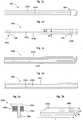
- Figure 1a depicts a schematic side view of a connecting element 100 according to a first embodiment.
- the connecting element 100 serves for establishing an electrically conductive connection between two further elements, which are not depicted in figure 1a .
- the connecting element 100 comprises a first layer 102a of a first material, and a second layer 102b of a second material, which is different from the first material.
- the various layers 102a, 102b of the connecting element 100 are arranged in a stacked configuration as depicted by figure 1a , i.e. the first layer is arranged on top of the second layer in the depiction of figure 1a .
- Both layers 102a, 102b are preferably made of sheet metal, wherein the first layer 102a is for example made of stainless steel, and wherein the second layer 102b is made of aluminium.
- the material combination of stainless steel and aluminium offers a comparatively high mechanical robustness, particularly a high tensile strength, due to the stainless steel layer 102a. Moreover, a good electrical conductivity is ensured by using aluminium for the second layer 102b. Further, the layer configuration of a plurality of layers 102a, 102b, each of which may e.g. be comparatively thin such as e.g. 0.1 mm to e.g. 2.0 mm, advantageously results in a high mechanical flexibility so that the connecting element 100 can easily be bent for installation purposes. At least one mounting section 106 is provided, which enables to establish a mechanical and/or electrical contact between the connecting element 100 and further elements to be connected thereto.
- Figure 1b depicts a connecting element 100a.
- the first layer 102a comprises a layer thickness d2, whereas the second layer 102b comprises a layer thickness d1.
- the layer thickness d2 is larger than the layer thickness d1.
- Each layer 102a, 102b may comprise a substantially rectangular cross-section. However, different layers may also exhibit different cross-sections or cross-sectional shapes.
- the mounting section 106 may also comprise one or more holes arranged within said layers 102a, 102b.
- each of both opposing end sections 104a, 104b comprises one hole, which enables mounting of said connecting element 100a by means of a bolt or a threaded bolt/screw connection or the like.
- Figure 1c depicts a schematic side view of a further embodiment 100b, wherein the connecting element 100b comprises seven layers 102c, ..., 102d, which ensures a good electrical conductivity and a high mechanical flexibility.
- the embodiment 100b does not require any crimp joints, but may rather also be attached to other elements by means of screws or bolts, which ensures both a low contact resistance and a mechanical robust connection to these other elements.
- Figure 1d depicts a connecting element 100c according to a further embodiment.
- the outer layers 102a, 102c (i.e. in Fig. 1d the top and bottom layers) of the connecting element 100c according to figure 1d are preferably made of stainless steel, wherein an intermediate layer 102b that is arranged within said stacked configuration between the outer layers 102a, 102c is e.g. made of copper or aluminium.
- an intermediate layer 102b that is arranged within said stacked configuration between the outer layers 102a, 102c is e.g. made of copper or aluminium.
- stainless steel layers 102a, 102c reduce this undesired effect.
- the stainless steel layers 102a, 102c advantageously contribute to the tensile strength of the connecting element 100c, while the intermediate aluminium or copper layer 102b effects a good electrical conductivity.
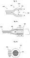
- Figure 2a shows an end section 104b of a connecting element according to a further embodiment.
- a bolt or threaded bolt 106a may be provided integrally with said third layer 102c. This may e.g. be attained by providing a sheet metal for defining the layer 102c, by providing a threaded bolt 106a of the same or a different, but weldable, material, and by welding both components 102c, 106a to form one single monolithic component.
- layer 102a also is made of stainless steel to avoid contact corrosion
- layer 102b is again made of aluminium or copper.
- the end section 104b as depicted by figure 2a can e.g. be used for easy mounting of the connecting element to a further element which e.g. comprises a hole or nut portion that can cooperate with said threaded bolt 106a.
- Figure 2b depicts a schematic view of one single layer of a connecting element according to a further embodiment.
- the layer 102a has in its end section at least one hole 106b which enables mounting by means of a screw connection or the like.
- at least one further hole may also be provided in the end section.
- At least one layer presently e.g. layer 102a of figure 2b , or the sheet metal which represents said layer 102a, respectively, comprises a substantially rectangular shape wherein a width W and a length L of said layer 102a are large compared to a layer thickness d2 ( fig. 1b ) of the respective layer.
- L defines a length and W defines a width of the basically rectangular portion of sheet metal defining a specific layer 102a
- the thickness of said layer is defined by d ⁇ L/10 and/or d ⁇ W/5.
- the length L and width W may comprise a ratio of L / W > 10, which results in a rectangular strip-type shape.
- Figure 2c schematically depicts a side view of a connecting element 100d according to a further embodiment.
- the groups g1, g2 together comprise all six layers of the connecting element 100d.
- further layers may be provided which contribute to an aggregated cross-section area and thus to electrical conductivity, but which do not contribute to mounting the connecting element 100d.
- Such further layers may also comprise a reduced length L ( fig. 2b ) as compared to the layers forming part of the groups g1, g2 to prevent them from extending into the end section 104b.
- the end sections of the different groups g1, g2 are spaced apart by a non-vanishing distance d3 from each other, whereby a receiving section 106c is defined.
- the end sections 104b of the groups g1, g2 may also comprise through holes 106b for applying a screw connection to a further mounting element that can be introduced into the receiving section 106c.
- any of the end sections depicted by figure 2a, figure 2b , figure 2c may be applied to either one end portion 104a, 104b or to both end portions 104a, 104b of any connecting element described above.
- a connecting element may have similar or identical end portions or mounting sections 106 or different end portions or mounting sections.
- Figure 3a depicts connecting element 100d in a mounting position at a body unit 200, which is part of a grounding kit for a cable 400.
- the body unit 200 is of the clamp type and comprises a basically C-shaped cross section, also cf. figure 3b .
- the body unit 200 is mounted on the cable 400 such that a radially inner section of the body unit 200 (not shown) establishes electrically conductive contact with an outer conductor (not shown) of the cable 400. For this purpose, portions of an isolating jacket (not shown) of cable 400 must be removed to enable said contact.
- the connecting element 100d is connected to the body unit 200 by means of two screws 106d, which are received in respective holes 106b ( figure 2c ) of the connecting element 100d. Due to its plurality of single layers, the connecting element 100d is mechanically flexible and can thus easily be mounted at the body unit 200 and the cable 400. Nevertheless, due to the aggregated cross section of the multiple layers, a good electrical connectivity is achieved. Moreover, a good tensile strength is also attained, because one or more layers may be formed of material having a greater tensile strength than the good electrical conductors aluminium or copper.
- the screw connection 106d can easily be made in the field, whereby costs for installing the connecting element 100d and the body unit 200 are reduced.
- figure 3b depicts a partial cross-section of the arrangement of figure 3a . It can be seen that by means of the screws 106d ( figure 3a ) both the clamping mechanism of the body unit 200 is locked around the cable 400 and the electrical and mechanical connection between the body unit 200 and the connecting element 100d ( figure 3a ) is established by means of the screws 106d, which is advantageous since no further components are required for locking the connecting element 100d to the body unit 200 and for locking the body unit 200 to the cable 400.
- 3a has the further advantage of a very large contact surface between electrically conducting portions of the body unit 200 and the connecting element 100d, since surface portions of both groups g1, g2 of layers are used for establishing the contact, whereby a contact resistance is further reduced. Moreover, since both end sections of the C-shaped clamp element of the body unit 200 are contacted by a respective layer group g1, g2, the overall Ohmic resistance between the cable 400 and the connecting element 100d is even further reduced.
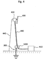
- Figure 4 depicts a schematic view of an operational scenario of a grounding kit 1000 according to an embodiment.
- the grounding kit 1000 comprises a body unit 200 as explained above with reference to figure 3a, 3b and a connecting element according to any of the above explained embodiments.
- FIG. 4 depicts an antenna tower 440 which carries a remote radio head 420 that is connected to a base station antenna system 430.
- a base station unit 410 is arranged on a ground floor, i.e. in a separate building arranged close to the antenna tower 440.
- the cable 400 establishes an electric and/or optic connection between the base station unit 410 and the remote radio head 420.
- the grounding kit 1000 for protecting the units 410, 420, 430 against lightning strikes, the grounding kit 1000 according to the embodiments is provided which establishes an electrically conductive connection between a radially outer conductor of the cable 400, which may for example comprise a hybrid cable or a coaxial cable, and a grounding element 300 of the antenna tower 440, which may e.g.
- the body unit 200 for example as a foundation earth electrode or which may be directly connected to a steel frame construction of the antenna tower 440 or the like.
- the body unit 200 For contacting the cable 400 or its outer conductor respectively, the body unit 200 as depicted by figure 3a, 3b is provided around the cable 400.
- An electrically conductive connection between the body unit 200 and the grounding element 300 of the antenna tower 440 is established by at least one connecting element according to the embodiments, which is not shown in figure 4 .
- connecting element 100d according to figure 3a may be used for establishing an electrically conductive connection between the body unit 200, the cable 400, and the grounding element 300 of the antenna tower 440.
- More than one grounding kit 1000 may be provided for a cable (i.e.
- a first grounding kit may e.g. be placed close to the antenna
- a second grounding kit may e.g. be placed as depicted by Fig. 4
- a third grounding kit may e.g. be placed close to the shelter 410, i.e. at a shelter entry, to provide further improved lightning protection for all components.
- both a good electrical conductivity, i.e. a low Ohmic resistance, and a large tensile strength is achieved for the connecting element 100, 100a, 100b, 100c, 100d, which is important since tensile forces resulting from electromagnetic field forces that may occur during a lightning strike may amount up to 2400 Newton and even more.
- the connecting element according to the embodiments can be attached to and locked at further elements 200, 300 by using screw connections or bolts or the like, which are more robust than the crimp connections.
- a particular advantage of the connecting element according to the embodiments is its high mechanical flexibility which facilitates installation on site, i.e. in the field.
- the highly conductive layers 102b ( figure 1d ) and the mechanical strong material layers (102a, 102c) are calculated such that on one hand the effective conductivity of the overall connecting element is equivalent to or higher than what is required by the relevant standards, which e.g. require a copper cross-section of 16 mm 2 or above for sufficient electrical conductivity.
- the connecting element may be connected to a ground bar 300 of a building such as an antenna tower 440 or the like, the ground bar 300 usually being made of copper or stainless steel. In many cases, the ground bar may also be implemented in the form of a galvanized steel bar with a zinc surface.
- the preferred embodiment proposes to use outer layers 102a, 102c ( figure 1d ) of stainless steel (or even noble metal or noble metal coating, i.e. silver coating), and one or more intermediate layers 102b of aluminium or copper, whereby contact corrosion is minimized and at the same time a low resistance is obtained.
- the connecting element according to the embodiments provides higher product reliability as compared to conventional systems. At the same time, the electrical contact resistance is reduced which leads to an improved lightning protection.
- a comparatively large outer surface is given for the connecting element, which improves heat dissipation thus further enabling larger maximum currents for the connecting element according to the embodiments.
- the layer construction according to the embodiments may even be configured in the field, i.e. by cutting respective preformed pieces of sheet metal.
- holes may e.g. be applied to the sheet metal by punching or drilling for enabling a screw connecting and the like.
- the layers of the connecting element according to an embodiment can be adapted with simple means or tools to different sizes of through holes and regarding the number of holes for the screw connections.
- one or more layers of the connecting element may e.g. be non-detachably attached to the body unit 200 of the grounding kit, i.e. by welding, wherein a cost-effective ultrasonic welding process may be employed.
- a cross-section of the connecting element 100 is equal to or greater than about 10 mm 2 (square millimeter), which ensures a sufficient electric conductivity for handling electric currents, particularly surge currents during a lightning strike, without damage to the connecting element 100.
- the connecting element 100 comprises a tensile strength (also referred to as “ultimate tensile strength", UTS) of about 2500 Newton or more.
- the tensile strength is also denoted as physical parameter "Rm” and defines the maximum stress that a material can withstand while being stretched before failing / breaking.
- Rm physical parameter
- the connecting element 100 is designed such that it can withstand tensile forces of about 2500 Newton or more without breaking.
- the connecting element 100 comprises an electrical resistance R of about 2 mOhm/m (milliohm per meter) or less.
- the layer construction of the connecting element advantageously enables different layers to contribute to an overall, i.e. aggregated, cross-section and/or electric conductivity and/or tensile strength, wherein contributions to one or more of these parameters of individual layers may differ from those contributions of another layer.
- at least one layer 102a may primarily contribute to an overall low electric resistance, while another layer 102b may primarily contribute to an overall high tensile strength.
Landscapes
- Cable Accessories (AREA)
Claims (15)
- Verbindungselement (100) für das Herstellen einer elektrisch leitfähigen Verbindung zwischen zwei weiteren Elementen (200, 300), konkret für das Verbinden einer Gehäuseeinheit (200) eines Erdungskits (1000) mit einem Erdungselement (300), wobei besagtes Verbindungselement (100) mindestens drei Schichten (102a, 102b, 102c) elektrisch leitfähigen Materials umfasst, wobei mindestens zwei Schichten (102a, 102b) verschiedene Materialien umfassen und wobei mindestens zwei Schichten dasselbe Material umfassen, dadurch gekennzeichnet, dass besagtes Verbindungselement mechanisch flexibel ist.
- Verbindungselement (100) nach Anspruch 1, wobei mindestens eine Schicht (102a) Kupfer und/oder Aluminium umfasst.
- Verbindungselement (100) nach einem der vorgenannten Ansprüche, wobei mindestens eine Schicht (102c) ein anderes Material als Kupfer oder Aluminium umfasst, vorzugsweise ein Material mit einer höheren Zugtragfähigkeit als Kupfer oder Aluminium, namentlich Edelstahl.
- Verbindungselement (100) nach einem der vorgenannten Ansprüche, wobei äußere Schichten (102a, 102c) besagten Verbindungselements (100) aus Edelstahl gefertigt sind und wobei mindestens eine innere, zwischen besagten äußeren Schichten (102a, 102c) angeordnete Schicht (102b) des besagten Verbindungselements (100) aus Aluminium oder Kupfer hergestellt ist.
- Verbindungselement (100) nach einem der vorgenannten Ansprüche, wobei mindestens zwei Schichten dieselbe oder verschiedene Schichtdicken (d1, d2) haben.
- Verbindungselement (100) nach einem der vorgenannten Ansprüche, wobei mindestens eine Schicht - vorzugsweise jedoch alle Schichten zumindest teilweise von einer Umhüllung umgeben sind.
- Verbindungselement (100) nach einem der vorgenannten Ansprüche, wobei besagtes Verbindungselement (100) einen Halterungsbereich (106) zum Verbinden mit besagtem weiteren Element (200, 300) umfasst.
- Verbindungselement (100) nach Anspruch 7, wobei besagter Halterungsbereich (106) mindestens ein Loch (106b) und/oder einen vorzugsweise mit einem Gewinde versehenen Bolzen (106a) umfasst.
- Verbindungselement (100) nach Anspruch 7 oder 8, wobei zum Definieren besagten Halterungsbereichs (106) zwei Gruppen (g1, g2) besagter Schichten gebildet werden und wobei in einem Endabschnitt (104b) besagten Verbindungselements (100) beide Gruppen (g1, g2) in einem festen Abstand (d3) zwischen einander angeordnet sind, um einen Aufnahmeabschnitt (106c) für die Aufnahme einer Komponente der besagten, weiteren Elemente (200, 300) zu definieren.
- Verbindungselement (100) nach einem der vorgenannten Ansprüche, wobei mindestens eines der folgenden Kriterien erfüllt wird:a. ein Querschnitt des Verbindungselements (100), konkret ein Gesamtquerschnitt aller elektrisch leitfähigen Komponenten bzw. aller Schichten (102a, 102b) ist gleich oder größer als rund 10 Quadratmillimeter,b. das Verbindungselement (100) umfasst eine Zugtragfähigkeit, vorzugsweise Reißfestigkeit, von rund 2500 Newton oder höher,c. das Verbindungselement (100) umfasst einen elektrischen Widerstand von 2 mOhm/m oder weniger.
- Erdungskit (1000) für das Verbinden eines Kabels (400) mit einem Erdungselement (300), wobei besagtes Erdungskit (1000) mindestens ein Verbindungselement (100, 100a, 100b, 100c, 100d) nach einem der vorgenannten Ansprüche umfasst und wobei besagtes Erdungskit (1000) weiterhin eine Gehäuseeinheit (200) umfasst, die konfiguriert ist für das Herstellen einer elektrisch leitfähigen Verbindung mit einer Komponente besagten Kabels (400).
- Erdungskit (1000) nach Anspruch 11, wobei besagtes Verbindungselement (100, 100a, 100b, 100c, 100d) lösbar an besagter Gehäuseeinheit (200) befestigt ist, und zwar konkret anhand einer oder mehrerer Schrauben (106d) und/oder Klemmenmechanismen.
- Erdungskit (1000) nach Anspruch 11, wobei besagtes Verbindungselement (100, 100a, 100b, 100c, 100d) unlösbar an besagter Gehäuseeinheit (200) befestigt ist, und zwar konkret anhand einer Verschweißung, vorzugsweise einer Ultaschallverschweißung.
- Erdungskit (1000) nach einem der Ansprüche 11 bis 13, wobei es besagte Gehäuseeinheit (200) ermöglicht, eine wasserdichte elektrisch leitfähige Verbindung mit einer Komponente besagten Kabels (400) herzustellen.
- Verfahren für die Herstellung eines Verbindungselements (100) für das Herstellen einer elektrisch leitfähigen Verbindung zwischen zwei weiteren Elementen (200, 300), konkret für das Verbinden einer Gehäuseeinheit (200) eines Erdungskits (1000) mit einem Erdungselement (300), wobei mindestens drei Schichten (102a, 102b, 102c) elektrisch leitfähigen Materials zur Verfügung gestellt werden, wobei mindestens zwei der besagten Schichten (102a, 102b) verschiedene Materialien umfassen, wobei die besagten, mindestens zwei Schichten (102a, 102b) elektrisch leitfähigen Materials dergestalt zur Verfügung gestellt werden, dass besagtes Verbindungselement (100) mechanisch flexibel ist, und wobei mindestens zwei Schichten dasselbe Material umfassen.
Priority Applications (1)
| Application Number | Priority Date | Filing Date | Title |
|---|---|---|---|
| EP13153250.9A EP2763243B1 (de) | 2013-01-30 | 2013-01-30 | Verbindungselement und Verfahren zur Herstellung eines Verbindungselements |
Applications Claiming Priority (1)
| Application Number | Priority Date | Filing Date | Title |
|---|---|---|---|
| EP13153250.9A EP2763243B1 (de) | 2013-01-30 | 2013-01-30 | Verbindungselement und Verfahren zur Herstellung eines Verbindungselements |
Publications (2)
| Publication Number | Publication Date |
|---|---|
| EP2763243A1 EP2763243A1 (de) | 2014-08-06 |
| EP2763243B1 true EP2763243B1 (de) | 2017-06-07 |
Family
ID=47630194
Family Applications (1)
| Application Number | Title | Priority Date | Filing Date |
|---|---|---|---|
| EP13153250.9A Active EP2763243B1 (de) | 2013-01-30 | 2013-01-30 | Verbindungselement und Verfahren zur Herstellung eines Verbindungselements |
Country Status (1)
| Country | Link |
|---|---|
| EP (1) | EP2763243B1 (de) |
Cited By (1)
| Publication number | Priority date | Publication date | Assignee | Title |
|---|---|---|---|---|
| US12573826B2 (en) | 2022-08-22 | 2026-03-10 | Erico International Corporation | Cable entry system for electrical enclosures |
Families Citing this family (1)
| Publication number | Priority date | Publication date | Assignee | Title |
|---|---|---|---|---|
| EP3490071A1 (de) * | 2017-11-22 | 2019-05-29 | Tyco Electronics Services GmbH | Elektrische anschlussvorrichtung |
Citations (2)
| Publication number | Priority date | Publication date | Assignee | Title |
|---|---|---|---|---|
| WO2007049834A1 (en) * | 2005-10-25 | 2007-05-03 | Kui-Yeun Kim | The constitution and method making of the stainless covered wire |
| EP2398112A1 (de) * | 2010-06-16 | 2011-12-21 | Alcatel Lucent | Koaxialstecker zum Abschließen eines Koaxialkabels, Koaxialkabel und Basisstation |
Family Cites Families (5)
| Publication number | Priority date | Publication date | Assignee | Title |
|---|---|---|---|---|
| US6422900B1 (en) * | 1999-09-15 | 2002-07-23 | Hh Tower Group | Coaxial cable coupling device |
| JP2005314749A (ja) * | 2004-04-28 | 2005-11-10 | Shinei Hitec:Kk | 電子部品及びその表面処理方法 |
| DE102006025870A1 (de) * | 2006-06-02 | 2007-12-06 | Robert Bosch Gmbh | Mehrschichtiges Bond-Bändchen |
| WO2008076813A2 (en) * | 2006-12-13 | 2008-06-26 | Panduit Corp. | Communication jack having layered plug interface contacts |
| US7976333B2 (en) * | 2009-09-29 | 2011-07-12 | Flex-Cable | Laminar electrical connector |
-
2013
- 2013-01-30 EP EP13153250.9A patent/EP2763243B1/de active Active
Patent Citations (2)
| Publication number | Priority date | Publication date | Assignee | Title |
|---|---|---|---|---|
| WO2007049834A1 (en) * | 2005-10-25 | 2007-05-03 | Kui-Yeun Kim | The constitution and method making of the stainless covered wire |
| EP2398112A1 (de) * | 2010-06-16 | 2011-12-21 | Alcatel Lucent | Koaxialstecker zum Abschließen eines Koaxialkabels, Koaxialkabel und Basisstation |
Cited By (1)
| Publication number | Priority date | Publication date | Assignee | Title |
|---|---|---|---|---|
| US12573826B2 (en) | 2022-08-22 | 2026-03-10 | Erico International Corporation | Cable entry system for electrical enclosures |
Also Published As
| Publication number | Publication date |
|---|---|
| EP2763243A1 (de) | 2014-08-06 |
Similar Documents
| Publication | Publication Date | Title |
|---|---|---|
| US9985362B2 (en) | Arc resistant power terminal | |
| EP3130043B1 (de) | Einstellbare sammelschiene für leistungsverteilungssystem | |
| JP2018531502A6 (ja) | 耐アーク性電力端子 | |
| US8410378B1 (en) | Grounding fitting | |
| US10290986B2 (en) | Systems and methods for connecting power distribution devices | |
| CA2965161C (en) | Pad extending member | |
| CN109285633B (zh) | 利用金属芯线制造汇流排的方法以及汇流排 | |
| JP6118823B2 (ja) | 非導電性構造体内の電流リターン回路網の接続方法、等電位シャント接続、および等電位ボンディング | |
| EP2763243B1 (de) | Verbindungselement und Verfahren zur Herstellung eines Verbindungselements | |
| US7170459B1 (en) | Split lead antenna system | |
| US12080449B2 (en) | Power conductor and system | |
| US8581115B2 (en) | Grounding bar/hatchplate for use with lightning arrestors | |
| US9509068B2 (en) | Creepage design terminal strip | |
| KR20110054540A (ko) | 반금속 가스켓을 이용한 부스 덕트 접속부 | |
| US20140292609A1 (en) | Device and Process for Reduction of Passive Intermodulation | |
| US20180090855A1 (en) | Connecting Element for Contacting a Shielding of a Power Cable | |
| US6888507B2 (en) | Split lead antenna system | |
| CN213636630U (zh) | 一种配电柜母线连接器 | |
| DE102005058029B4 (de) | Stromzuleitung für kryogene elektrische Systeme | |
| KR101169034B1 (ko) | 고주파 전선 커넥터 | |
| US20030037944A1 (en) | Flexible electrical coupling with conductive bonding jumper | |
| JP7536427B2 (ja) | アルミ導体ケーブルの端子台への接続構造、端子台及び端子 | |
| KR200458499Y1 (ko) | 케이블 압착 단자 | |
| EP2166621A1 (de) | Erdungsvorrichtung | |
| EP2882039A1 (de) | Koaxialkabel mit nicht lötbarem Materialübergang |
Legal Events
| Date | Code | Title | Description |
|---|---|---|---|
| PUAI | Public reference made under article 153(3) epc to a published international application that has entered the european phase |
Free format text: ORIGINAL CODE: 0009012 |
|
| 17P | Request for examination filed |
Effective date: 20140326 |
|
| AK | Designated contracting states |
Kind code of ref document: A1 Designated state(s): AL AT BE BG CH CY CZ DE DK EE ES FI FR GB GR HR HU IE IS IT LI LT LU LV MC MK MT NL NO PL PT RO RS SE SI SK SM TR |
|
| AX | Request for extension of the european patent |
Extension state: BA ME |
|
| RBV | Designated contracting states (corrected) |
Designated state(s): AL AT BE BG CH CY CZ DE DK EE ES FI FR GB GR HR HU IE IS IT LI LT LU LV MC MK MT NL NO PL PT RO RS SE SI SK SM TR |
|
| 17Q | First examination report despatched |
Effective date: 20150610 |
|
| GRAP | Despatch of communication of intention to grant a patent |
Free format text: ORIGINAL CODE: EPIDOSNIGR1 |
|
| RIC1 | Information provided on ipc code assigned before grant |
Ipc: H01R 4/66 20060101ALN20160907BHEP Ipc: H01R 9/05 20060101ALN20160907BHEP Ipc: H01R 13/03 20060101ALI20160907BHEP Ipc: H01R 4/30 20060101ALN20160907BHEP Ipc: H01R 4/62 20060101AFI20160907BHEP Ipc: H01R 4/38 20060101ALN20160907BHEP Ipc: H01R 4/64 20060101ALI20160907BHEP |
|
| INTG | Intention to grant announced |
Effective date: 20160927 |
|
| GRAJ | Information related to disapproval of communication of intention to grant by the applicant or resumption of examination proceedings by the epo deleted |
Free format text: ORIGINAL CODE: EPIDOSDIGR1 |
|
| GRAJ | Information related to disapproval of communication of intention to grant by the applicant or resumption of examination proceedings by the epo deleted |
Free format text: ORIGINAL CODE: EPIDOSDIGR1 |
|
| GRAS | Grant fee paid |
Free format text: ORIGINAL CODE: EPIDOSNIGR3 |
|
| GRAP | Despatch of communication of intention to grant a patent |
Free format text: ORIGINAL CODE: EPIDOSNIGR1 |
|
| INTC | Intention to grant announced (deleted) | ||
| INTG | Intention to grant announced |
Effective date: 20170109 |
|
| RIC1 | Information provided on ipc code assigned before grant |
Ipc: H01R 4/62 20060101AFI20161216BHEP Ipc: H01R 4/66 20060101ALN20161216BHEP Ipc: H01R 4/30 20060101ALN20161216BHEP Ipc: H01R 4/64 20060101ALI20161216BHEP Ipc: H01R 4/38 20060101ALN20161216BHEP Ipc: H01R 13/03 20060101ALI20161216BHEP Ipc: H01R 9/05 20060101ALN20161216BHEP |
|
| AK | Designated contracting states |
Kind code of ref document: B1 Designated state(s): AL AT BE BG CH CY CZ DE DK EE ES FI FR GB GR HR HU IE IS IT LI LT LU LV MC MK MT NL NO PL PT RO RS SE SI SK SM TR |
|
| REG | Reference to a national code |
Ref country code: GB Ref legal event code: FG4D |
|
| GRAA | (expected) grant |
Free format text: ORIGINAL CODE: 0009210 |
|
| REG | Reference to a national code |
Ref country code: CH Ref legal event code: EP Ref country code: AT Ref legal event code: REF Ref document number: 899856 Country of ref document: AT Kind code of ref document: T Effective date: 20170615 |
|
| REG | Reference to a national code |
Ref country code: IE Ref legal event code: FG4D |
|
| REG | Reference to a national code |
Ref country code: DE Ref legal event code: R096 Ref document number: 602013021874 Country of ref document: DE |
|
| REG | Reference to a national code |
Ref country code: NL Ref legal event code: MP Effective date: 20170607 |
|
| REG | Reference to a national code |
Ref country code: LT Ref legal event code: MG4D |
|
| PG25 | Lapsed in a contracting state [announced via postgrant information from national office to epo] |
Ref country code: NO Free format text: LAPSE BECAUSE OF FAILURE TO SUBMIT A TRANSLATION OF THE DESCRIPTION OR TO PAY THE FEE WITHIN THE PRESCRIBED TIME-LIMIT Effective date: 20170907 Ref country code: FI Free format text: LAPSE BECAUSE OF FAILURE TO SUBMIT A TRANSLATION OF THE DESCRIPTION OR TO PAY THE FEE WITHIN THE PRESCRIBED TIME-LIMIT Effective date: 20170607 Ref country code: LT Free format text: LAPSE BECAUSE OF FAILURE TO SUBMIT A TRANSLATION OF THE DESCRIPTION OR TO PAY THE FEE WITHIN THE PRESCRIBED TIME-LIMIT Effective date: 20170607 Ref country code: GR Free format text: LAPSE BECAUSE OF FAILURE TO SUBMIT A TRANSLATION OF THE DESCRIPTION OR TO PAY THE FEE WITHIN THE PRESCRIBED TIME-LIMIT Effective date: 20170908 Ref country code: HR Free format text: LAPSE BECAUSE OF FAILURE TO SUBMIT A TRANSLATION OF THE DESCRIPTION OR TO PAY THE FEE WITHIN THE PRESCRIBED TIME-LIMIT Effective date: 20170607 Ref country code: ES Free format text: LAPSE BECAUSE OF FAILURE TO SUBMIT A TRANSLATION OF THE DESCRIPTION OR TO PAY THE FEE WITHIN THE PRESCRIBED TIME-LIMIT Effective date: 20170607 |
|
| REG | Reference to a national code |
Ref country code: AT Ref legal event code: MK05 Ref document number: 899856 Country of ref document: AT Kind code of ref document: T Effective date: 20170607 |
|
| PG25 | Lapsed in a contracting state [announced via postgrant information from national office to epo] |
Ref country code: LV Free format text: LAPSE BECAUSE OF FAILURE TO SUBMIT A TRANSLATION OF THE DESCRIPTION OR TO PAY THE FEE WITHIN THE PRESCRIBED TIME-LIMIT Effective date: 20170607 Ref country code: NL Free format text: LAPSE BECAUSE OF FAILURE TO SUBMIT A TRANSLATION OF THE DESCRIPTION OR TO PAY THE FEE WITHIN THE PRESCRIBED TIME-LIMIT Effective date: 20170607 Ref country code: BG Free format text: LAPSE BECAUSE OF FAILURE TO SUBMIT A TRANSLATION OF THE DESCRIPTION OR TO PAY THE FEE WITHIN THE PRESCRIBED TIME-LIMIT Effective date: 20170907 Ref country code: RS Free format text: LAPSE BECAUSE OF FAILURE TO SUBMIT A TRANSLATION OF THE DESCRIPTION OR TO PAY THE FEE WITHIN THE PRESCRIBED TIME-LIMIT Effective date: 20170607 Ref country code: SE Free format text: LAPSE BECAUSE OF FAILURE TO SUBMIT A TRANSLATION OF THE DESCRIPTION OR TO PAY THE FEE WITHIN THE PRESCRIBED TIME-LIMIT Effective date: 20170607 |
|
| REG | Reference to a national code |
Ref country code: FR Ref legal event code: PLFP Year of fee payment: 6 |
|
| PG25 | Lapsed in a contracting state [announced via postgrant information from national office to epo] |
Ref country code: EE Free format text: LAPSE BECAUSE OF FAILURE TO SUBMIT A TRANSLATION OF THE DESCRIPTION OR TO PAY THE FEE WITHIN THE PRESCRIBED TIME-LIMIT Effective date: 20170607 Ref country code: CZ Free format text: LAPSE BECAUSE OF FAILURE TO SUBMIT A TRANSLATION OF THE DESCRIPTION OR TO PAY THE FEE WITHIN THE PRESCRIBED TIME-LIMIT Effective date: 20170607 Ref country code: SK Free format text: LAPSE BECAUSE OF FAILURE TO SUBMIT A TRANSLATION OF THE DESCRIPTION OR TO PAY THE FEE WITHIN THE PRESCRIBED TIME-LIMIT Effective date: 20170607 Ref country code: RO Free format text: LAPSE BECAUSE OF FAILURE TO SUBMIT A TRANSLATION OF THE DESCRIPTION OR TO PAY THE FEE WITHIN THE PRESCRIBED TIME-LIMIT Effective date: 20170607 Ref country code: AT Free format text: LAPSE BECAUSE OF FAILURE TO SUBMIT A TRANSLATION OF THE DESCRIPTION OR TO PAY THE FEE WITHIN THE PRESCRIBED TIME-LIMIT Effective date: 20170607 |
|
| PG25 | Lapsed in a contracting state [announced via postgrant information from national office to epo] |
Ref country code: PL Free format text: LAPSE BECAUSE OF FAILURE TO SUBMIT A TRANSLATION OF THE DESCRIPTION OR TO PAY THE FEE WITHIN THE PRESCRIBED TIME-LIMIT Effective date: 20170607 Ref country code: IT Free format text: LAPSE BECAUSE OF FAILURE TO SUBMIT A TRANSLATION OF THE DESCRIPTION OR TO PAY THE FEE WITHIN THE PRESCRIBED TIME-LIMIT Effective date: 20170607 Ref country code: SM Free format text: LAPSE BECAUSE OF FAILURE TO SUBMIT A TRANSLATION OF THE DESCRIPTION OR TO PAY THE FEE WITHIN THE PRESCRIBED TIME-LIMIT Effective date: 20170607 Ref country code: IS Free format text: LAPSE BECAUSE OF FAILURE TO SUBMIT A TRANSLATION OF THE DESCRIPTION OR TO PAY THE FEE WITHIN THE PRESCRIBED TIME-LIMIT Effective date: 20171007 |
|
| REG | Reference to a national code |
Ref country code: DE Ref legal event code: R097 Ref document number: 602013021874 Country of ref document: DE |
|
| PLBE | No opposition filed within time limit |
Free format text: ORIGINAL CODE: 0009261 |
|
| STAA | Information on the status of an ep patent application or granted ep patent |
Free format text: STATUS: NO OPPOSITION FILED WITHIN TIME LIMIT |
|
| PG25 | Lapsed in a contracting state [announced via postgrant information from national office to epo] |
Ref country code: DK Free format text: LAPSE BECAUSE OF FAILURE TO SUBMIT A TRANSLATION OF THE DESCRIPTION OR TO PAY THE FEE WITHIN THE PRESCRIBED TIME-LIMIT Effective date: 20170607 |
|
| 26N | No opposition filed |
Effective date: 20180308 |
|
| PG25 | Lapsed in a contracting state [announced via postgrant information from national office to epo] |
Ref country code: SI Free format text: LAPSE BECAUSE OF FAILURE TO SUBMIT A TRANSLATION OF THE DESCRIPTION OR TO PAY THE FEE WITHIN THE PRESCRIBED TIME-LIMIT Effective date: 20170607 |
|
| REG | Reference to a national code |
Ref country code: CH Ref legal event code: PL |
|
| PG25 | Lapsed in a contracting state [announced via postgrant information from national office to epo] |
Ref country code: LU Free format text: LAPSE BECAUSE OF NON-PAYMENT OF DUE FEES Effective date: 20180130 |
|
| REG | Reference to a national code |
Ref country code: IE Ref legal event code: MM4A |
|
| REG | Reference to a national code |
Ref country code: BE Ref legal event code: MM Effective date: 20180131 |
|
| PG25 | Lapsed in a contracting state [announced via postgrant information from national office to epo] |
Ref country code: BE Free format text: LAPSE BECAUSE OF NON-PAYMENT OF DUE FEES Effective date: 20180131 Ref country code: LI Free format text: LAPSE BECAUSE OF NON-PAYMENT OF DUE FEES Effective date: 20180131 Ref country code: CH Free format text: LAPSE BECAUSE OF NON-PAYMENT OF DUE FEES Effective date: 20180131 |
|
| PG25 | Lapsed in a contracting state [announced via postgrant information from national office to epo] |
Ref country code: IE Free format text: LAPSE BECAUSE OF NON-PAYMENT OF DUE FEES Effective date: 20180130 |
|
| PG25 | Lapsed in a contracting state [announced via postgrant information from national office to epo] |
Ref country code: MC Free format text: LAPSE BECAUSE OF FAILURE TO SUBMIT A TRANSLATION OF THE DESCRIPTION OR TO PAY THE FEE WITHIN THE PRESCRIBED TIME-LIMIT Effective date: 20170607 |
|
| PG25 | Lapsed in a contracting state [announced via postgrant information from national office to epo] |
Ref country code: MT Free format text: LAPSE BECAUSE OF NON-PAYMENT OF DUE FEES Effective date: 20180130 |
|
| PG25 | Lapsed in a contracting state [announced via postgrant information from national office to epo] |
Ref country code: TR Free format text: LAPSE BECAUSE OF FAILURE TO SUBMIT A TRANSLATION OF THE DESCRIPTION OR TO PAY THE FEE WITHIN THE PRESCRIBED TIME-LIMIT Effective date: 20170607 |
|
| PG25 | Lapsed in a contracting state [announced via postgrant information from national office to epo] |
Ref country code: PT Free format text: LAPSE BECAUSE OF FAILURE TO SUBMIT A TRANSLATION OF THE DESCRIPTION OR TO PAY THE FEE WITHIN THE PRESCRIBED TIME-LIMIT Effective date: 20170607 Ref country code: HU Free format text: LAPSE BECAUSE OF FAILURE TO SUBMIT A TRANSLATION OF THE DESCRIPTION OR TO PAY THE FEE WITHIN THE PRESCRIBED TIME-LIMIT; INVALID AB INITIO Effective date: 20130130 |
|
| PG25 | Lapsed in a contracting state [announced via postgrant information from national office to epo] |
Ref country code: CY Free format text: LAPSE BECAUSE OF FAILURE TO SUBMIT A TRANSLATION OF THE DESCRIPTION OR TO PAY THE FEE WITHIN THE PRESCRIBED TIME-LIMIT Effective date: 20170607 Ref country code: MK Free format text: LAPSE BECAUSE OF NON-PAYMENT OF DUE FEES Effective date: 20170607 |
|
| PG25 | Lapsed in a contracting state [announced via postgrant information from national office to epo] |
Ref country code: AL Free format text: LAPSE BECAUSE OF FAILURE TO SUBMIT A TRANSLATION OF THE DESCRIPTION OR TO PAY THE FEE WITHIN THE PRESCRIBED TIME-LIMIT Effective date: 20170607 |
|
| REG | Reference to a national code |
Ref country code: DE Ref legal event code: R082 Ref document number: 602013021874 Country of ref document: DE Representative=s name: DREISS PATENTANWAELTE PARTG MBB, DE |
|
| REG | Reference to a national code |
Ref country code: DE Ref legal event code: R081 Ref document number: 602013021874 Country of ref document: DE Owner name: RADIO FREQUENCY SYSTEMS GESELLSCHAFT MIT BESCH, DE Free format text: FORMER OWNER: ALCATEL-LUCENT SHANGHAI BELL CO., LTD., SHANGHAI, CN |
|
| REG | Reference to a national code |
Ref country code: GB Ref legal event code: 732E Free format text: REGISTERED BETWEEN 20250417 AND 20250423 |
|
| PGFP | Annual fee paid to national office [announced via postgrant information from national office to epo] |
Ref country code: GB Payment date: 20260113 Year of fee payment: 14 |
|
| PGFP | Annual fee paid to national office [announced via postgrant information from national office to epo] |
Ref country code: DE Payment date: 20260323 Year of fee payment: 14 |
|
| PGFP | Annual fee paid to national office [announced via postgrant information from national office to epo] |
Ref country code: FR Payment date: 20260128 Year of fee payment: 14 |