EP2762933B1 - "Betriebszustandswarnvorrichtung" - Google Patents
"Betriebszustandswarnvorrichtung" Download PDFInfo
- Publication number
- EP2762933B1 EP2762933B1 EP13005811.8A EP13005811A EP2762933B1 EP 2762933 B1 EP2762933 B1 EP 2762933B1 EP 13005811 A EP13005811 A EP 13005811A EP 2762933 B1 EP2762933 B1 EP 2762933B1
- Authority
- EP
- European Patent Office
- Prior art keywords
- warning light
- emission
- aforementioned
- radiating
- designed
- Prior art date
- Legal status (The legal status is an assumption and is not a legal conclusion. Google has not performed a legal analysis and makes no representation as to the accuracy of the status listed.)
- Active
Links
Images

Classifications
-
- F—MECHANICAL ENGINEERING; LIGHTING; HEATING; WEAPONS; BLASTING
- F21—LIGHTING
- F21V—FUNCTIONAL FEATURES OR DETAILS OF LIGHTING DEVICES OR SYSTEMS THEREOF; STRUCTURAL COMBINATIONS OF LIGHTING DEVICES WITH OTHER ARTICLES, NOT OTHERWISE PROVIDED FOR
- F21V3/00—Globes; Bowls; Cover glasses
- F21V3/02—Globes; Bowls; Cover glasses characterised by the shape
-
- G—PHYSICS
- G08—SIGNALLING
- G08B—SIGNALLING SYSTEMS, e.g. PERSONAL CALLING SYSTEMS; ORDER TELEGRAPHS; ALARM SYSTEMS
- G08B5/00—Visible signalling systems, e.g. visible personal calling systems or remote indication of seats occupied
- G08B5/22—Visible signalling systems, e.g. visible personal calling systems or remote indication of seats occupied using electric transmission; using electromagnetic transmission
- G08B5/36—Visible signalling systems, e.g. visible personal calling systems or remote indication of seats occupied using electric transmission; using electromagnetic transmission using visible light sources
-
- G—PHYSICS
- G02—OPTICS
- G02B—OPTICAL ELEMENTS, SYSTEMS OR APPARATUS
- G02B6/00—Light guides; Structural details of arrangements comprising light guides and other optical elements, e.g. couplings
- G02B6/0001—Light guides; Structural details of arrangements comprising light guides and other optical elements, e.g. couplings specially adapted for lighting devices or systems
- G02B6/0005—Light guides; Structural details of arrangements comprising light guides and other optical elements, e.g. couplings specially adapted for lighting devices or systems the light guides being of the fibre type
- G02B6/001—Light guides; Structural details of arrangements comprising light guides and other optical elements, e.g. couplings specially adapted for lighting devices or systems the light guides being of the fibre type the light being emitted along at least a portion of the lateral surface of the fibre
-
- G—PHYSICS
- G02—OPTICS
- G02B—OPTICAL ELEMENTS, SYSTEMS OR APPARATUS
- G02B6/00—Light guides; Structural details of arrangements comprising light guides and other optical elements, e.g. couplings
- G02B6/0001—Light guides; Structural details of arrangements comprising light guides and other optical elements, e.g. couplings specially adapted for lighting devices or systems
- G02B6/0011—Light guides; Structural details of arrangements comprising light guides and other optical elements, e.g. couplings specially adapted for lighting devices or systems the light guides being planar or of plate-like form
- G02B6/0033—Means for improving the coupling-out of light from the light guide
- G02B6/005—Means for improving the coupling-out of light from the light guide provided by one optical element, or plurality thereof, placed on the light output side of the light guide
- G02B6/0051—Diffusing sheet or layer
-
- G—PHYSICS
- G09—EDUCATION; CRYPTOGRAPHY; DISPLAY; ADVERTISING; SEALS
- G09F—DISPLAYING; ADVERTISING; SIGNS; LABELS OR NAME-PLATES; SEALS
- G09F9/00—Indicating arrangements for variable information in which the information is built-up on a support by selection or combination of individual elements
- G09F9/30—Indicating arrangements for variable information in which the information is built-up on a support by selection or combination of individual elements in which the desired character or characters are formed by combining individual elements
- G09F9/33—Indicating arrangements for variable information in which the information is built-up on a support by selection or combination of individual elements in which the desired character or characters are formed by combining individual elements being semiconductor devices, e.g. diodes
Definitions
- the invention relates to a Operating state warning light device for visual display of at least one operating state or of a plurality of different operating states of a technical device such as a machine, a system, a vehicle or the like according to the preamble of claim 1.
- Such operating state warning lights or signaling devices such as signal towers or the like have been in use for many years in a variety of variants.
- the classic signal tower with three interchangeable exchangeable modules is in use, which usually has the color combination red, yellow and green. Since signal towers are usually constructed in a modular manner, additional changeover modules in the colors blue or white, etc., can also be added or individual changeover modules can be removed under changing operating conditions.
- acoustic signal transmitters such as piezo discs or multi-tone generators or horns, etc. are integrated in the device, so that not only a visual, but also an acoustic signaling can take place.
- RGB-LED's also signal towers in use, which have a uniform dome and in trouble-free operation only a portion of the dome lights up with the color green, but can light up completely red in case of failure.
- RGB LEDs are also almost all conceivable luminous colors with a corresponding electronic control feasible.
- a warning light column with RGB LED's known which is freely configurable. This means that the user can configure one or more illumination parameters of the warning lights depending on the application.
- JP 2012-212525 discloses an operating state warning light device for optically indicating an operating state of a technical device.
- the calottes are hollow bodies, e.g. as a hollow cylinder, formed within which, usually centric, the bulbs such as LED, light bulb, etc. are arranged.
- These LEDs or warning light elements are the respective warning light source, wherein the visible light generated by the warning light element strikes the transparent dome through the hollow interior of the dome or the signal tower and is radiated outwardly therefrom or from its outer surface, so that corresponding persons light up of the respective module or the respective luminous color can recognize.
- the disadvantage here is that especially when using LEDs, which have a very narrow radiation direction, e.g. an all-round illumination of the hollow cylindrical dome by comparatively complicated and economically unfavorable arrangements of numerous LED's on mostly several tower-like to each other and along the central center line / longitudinal axis arranged printed circuit boards is necessary.
- the calottes to optimize the Light emission mostly on the inside elaborate geometric structures. Since the calottes are usually produced by casting methods, in particular by means of plastic casting methods, correspondingly complex and complex casting tools are necessary for the production of internally arranged, complex geometrical structures of the calottes. Accordingly economically unfavorable is the production of correspondingly complex calottes.
- the object of the invention is in contrast to propose a Radioswarnleuchtvorraum of the aforementioned type, which can be realized without great design effort, economically and with new design options.
- a device is characterized in that the warning light element is arranged on the front side surface for coupling the warning light in the radiating element and that the radiating element has scattering means for scattering the warning light, so that the warning light enters the radiating element via the front side surface and can be deflected to the radiating surface ,
- the light coupled in at the front side is deflected in an advantageous manner (by approximately 90 °) and decoupled from the emission element by the at least one warning light emitting surface or decoupled from the device according to the invention.
- the arrangement of LEDs for example, as warning light elements with less design effort is possible.
- an arrangement of the warning light elements with emission in and / or against the longitudinal or longitudinal axis of the device or signal device / signal tower are provided and by the advantageous deflection means of the scattering means, a lateral or transverse to Longitudinal direction or longitudinal axis directed coupling of the warning light can be realized.
- the end face is smaller than the warning light emitting surface.
- the space required for the warning light elements compared to the prior art can be reduced and / or a large-scale or structurally complex arrangement or placement of the warning light elements such as LED's according to the prior art can be omitted. moreover can be realized with the help of a comparatively small end face, in which the warning light is coupled, a particularly large or even an almost arbitrarily large Warnleuchtabstrahl
- a reflector or a reflector layer is arranged on a side face of the cover element, preferably on the side of the emission element which is opposite the warning light emission surface.
- the warning light from one side of the radiating element is passed through advantageous reflection through the entire thickness of the radiating element and coupled on the opposite side or on the Leuchtleuchtabstrahlization according to the invention to indicate the corresponding operating state of the technical device according to the invention ,
- the coupling of the warning light through the end face which is oriented substantially almost perpendicular to the coupling-in direction and / or to the emitting surface (s) of the emitting element, leads to the emitting surface (s) for a total reflection of the warning light. Due to the advantageous scattering means, however, the optical warning light is deflected in an advantageous manner such that optical warning light is not reflected by a total reflection back into the radiating element at these transverse / perpendicular to the end face radiating surfaces, but at the radiating surface or at this optical transition in can be coupled out more advantageous.
- the Scattering means as formed on the warning light emitting and / or surface of the radiating element arranged diffuser surface and / or diffuser layer.
- a light refractive layer arranged on the emission element and / or the diffuser layer is optically thinner or optically more dense than the emission element. This advantageously changes the optical transition or the refraction at the interface between the covering element and the layer or diffuser layer so that the warning light according to the invention decouples.
- the diffuser surface or the diffuser layer may at the same time comprise the warning light emitting surface. This means that in this case the warning light occurring on the diffuser surface or diffuser layer is not reflected back into the radiating element, but is deflected outwardly therefrom so that the diffuser surface or diffuser layer and / or the light refraction layer at the same time comprises the warning light emitting surface.
- An advantageous diffuser surface and / or diffuser layer can be arranged not only on the surface of the emission element, but also within the emission element. It has been found that this also advantageously the warning light can be coupled out by the warning light emitting surface. In addition, there are other novel design options, especially with respect to a two-sided decoupling of the warning light.
- an advantageous diffuser surface and / or diffuser layer can be realized in that the emission element has a turbidity.
- haze is realized by sand blasting, acid etching or the like.
- Sandblasting or acid etching of glass or plastic such as Plexiglas is preferably realized on the surface of the radiating element.
- turbidity or production of a diffuser surface or diffuser layer can be realized not only on the surface, that is to say on the outside, but also within the emission element by advantageous laser methods or the like.
- turbidity or production of a diffuser surface or diffuser layer can be realized not only on the surface, that is to say on the outside, but also within the emission element by advantageous laser methods or the like.
- a laser irradiation of the radiating element e.g. be realized by a laser irradiation of the radiating element, a diffuser surface on the surface and / or even also within the radiating element, wherein e.g. a material conversion is realized selectively or small area by thermal heating, so that at corresponding scattering centers the warning light according to the invention is deflected and is coupled out in an advantageous manner by the Warnleuchtabstrahl Structure.
- material removing processes i. Recesses or recesses and / or roughening / turbidity on the radiating element can be realized not only by means of sandblasting or the like, but also by machining processes.
- the roughened surface generated in this case can redirect the warning light according to the invention and advantageously decouple it from the warning light emitting surface.
- the scattering means are formed as arranged on and / or within the radiating element scattering body and / or scattering particles.
- Such scattering particles or scattering particles can already be stored or distributed during the production of the emission element.
- very fine-grained plastic particles and / or Particles of other material with light-refracting or scattering properties are stored.
- the body or particle diameter are smaller than the wavelength of the visible light, so that they lead to an advantageous design or are barely and / or not perceptible by a human eye within the radiating element. In this way, a completely transparent design of the radiating element can be realized in the off state, resulting in completely new design and design possibilities.
- the warning light is deflected to the advantageous scattering bodies or scattering particles and coupled out in an advantageous manner to the warning light emitting surface.
- the original transparent or transparent radiating element is accordingly correspondingly colored by the warning light and thereby perceived by corresponding persons in a special or surprising manner.
- the scattering bodies or scattering particles and / or the diffuser surfaces or diffuser layers are distributed uniformly or homogeneously on or in the emission element. This results in a homogeneous light extraction in the switched-on operating state.
- the arrangement or distribution of the scattering particles or scattering particles and / or the formation of the diffuser surface or diffuser layer is partial or only over a part or a partial surface of the emission element or the lateral surface of the device according to the invention. Accordingly, there is no homogeneous distribution, but rather a distribution which is different within predetermined, in particular homogeneous partial areas, and / or a partial, but inherently homogeneous, areal distribution of the scattering means according to this embodiment.
- patterns and / or symbols and / or Letters or text are generated in an advantageous manner.
- such patterns or letters or the like are only visible in the switched-on state or shine through the warning light in an advantageous manner and are almost invisible or transparent in the off state. This can in particular increase the attention of the appropriate people.
- the radiating element is formed essentially of solid material.
- the radiating element is designed as a plate or cylinder.
- a particularly flat device according to the invention can be realized.
- a device according to the invention can be realized with one or two centimeters thickness.
- the use according to plate-like devices according to the invention opens up completely new applications or design options.
- an end face with a width of about 0.5cm to 2cm can be provided and z.
- one of the two opposite radiating surfaces of about 10cm x 10cm or 20cm x 15cm or 10cm x 40cm etc. have. This can not only on one side of the plate a corresponding large-scale coupling of the warning light, but on the two opposite plate surfaces, the coupling can be realized.
- the radiating element is designed substantially as a cylinder or as a hollow cylinder, wherein preferably the height is greater than the outer diameter.
- the arrangement of the warning light elements takes place or the LEDs or the like according to the invention in the direction of the longitudinal axis or central axis, ie at the base surface / front side.
- the end face according to the invention is formed as a circle or circular ring on which the / the warning light elements are arranged.
- the warning light emitting surface according to the invention here is the lateral surface of the cylinder or the hollow cylinder.
- the cost of implementing a radiating element according to the invention in comparison with the prior art namely because corresponding complex geometric structures of the radiating element are dispensable.
- the manufacturing cost and thus the manufacturing costs compared to the prior art decreases.
- a device according to the invention can be used both as a single-stage and as a multi-stage operating state warning light device.
- a single radiating element or an assembly is used as a radiating element according to the invention, this may be useful for example in a single-stage but also in a multi-stage device or signal tower or the like.
- the operating state warning light device is a signal tower with at least three warning light units and / or three separately illuminated warning light output coupling surfaces and / or radiating elements formed.
- a multi-stage device or signal tower can be advantageously designed as a fixed preconfigured device according to the invention.
- the device / signal column preferably has releasably connectable and / or warning light-transmitting, optically connectable warning light units.
- plate-shaped radiating elements or even prismatic or cylindrical or even hollow cylindrical radiating elements can advantageously be connected to one another and formed releasably, so that a modular construction of a multi-stage device according to the invention can be realized without much effort.
- a variant in which at least one light-emitting element / LED or LED group per module is provided per module. Accordingly, a power supply or information data line to each module or to the warning light element or the LED / LED group is provided in these embodiments.
- the present invention in contrast to the prior art, in which in addition to the power supply of the individual modules or circuit boards and a separate information data line from module to module forwarded or provided detachably connectable, with the present invention, however, also realized an advantageous variant of the modularity be transmitted, whereby not electrical energy, but the optical, visible light from module to module on. That is, a module is designed as a light guide. In this case, the respective warning light is coupled out in a defined / predetermined manner per warning light unit. Accordingly, an optical-mechanical coupling or optical-mechanical connection between advantageous warning light units or radiating elements is provided in an advantageous manner, with which a multi-level warning light column according to the invention can be realized. ie that electrical connection lines or the like between the individual warning light units or radiating elements are dispensable, which significantly reduces the constructional and economic costs.
- a (common) base module (formed for example as a base and / or lid) for two or more warning light units or radiating elements
- the at least one or the warning light elements or LED or LED groups for the various warning light units and / or a has common electronic control unit.
- an advantageous basic module can have red, yellow and green LEDs which are each separately driven or operated in a specific operating mode.
- RGB LEDs even with the use of RGB LEDs, a multistage or multi-colored signal tower can be realized, whereby the RGB LEDs generate different colors and output them out on predetermined areas according to the invention.
- a common emission surface is provided for a plurality of different colors or units or else for different, separate emission surfaces.
- At least three radiating elements in the direction of the warning light decoupling are arranged one behind the other or side by side as a layer structure.
- separate warning colors or warning lights are provided per layer, so that each layer different colored warning lights are coupled according to the invention.
- several or all layers of the layer structure couple in almost the same direction or directions.
- the layer structure for example, in a multi-layered plate structure, the viewer looks on the front surface, recognizes this at least on the First glance the layer structure not, but this recognizes only when switching on or operation of a radiating element that the device according to the invention can decouple different warning light colors.
- it is transparent or, in normal operation of the technical device to be monitored, a first layer is green and in the case of a malfunction operation of the technical device to be monitored, a second layer or the second emitting element appears red in the device of the invention.
- At least two, preferably three radiating elements are arranged concentrically with each other.
- a cylindrical radiating element is arranged around which concentrically at least one hollow cylindrical radiating element or a plurality of hollow cylindrical, concentric radiating elements are arranged.
- the radiating elements according to the invention each have a circular or annular cross-section / end face on which the warning light elements are arranged.
- it is also square, rectangular or polygonal such. hexagonal / octagonal cross-sectional areas or rings / polygons conceivable.
- the warning light elements according to the invention are arranged on the front side and couple the warning light in an advantageous manner in or substantially parallel to the direction of the central axis or longitudinal axis in the respective radiating element. Due to the advantageous scattering means or scattering bodies and / or diffuser surfaces on the outer surface of the radiating elements and / or within the radiating elements, the warning light is deflected in an advantageous manner in such a way that it is substantially transverse to the (hollow) cylinder lateral surfaces or to the lateral surfaces decouple to the central axis or longitudinal axis and be perceived by the viewer.
- the radiating element has at least one diffuser or a diffuser element or a diffuser layer, so that the warning light decoupling can be realized particularly homogeneously distributed.
- This dispersion or homogenization of the warning light can be provided both on the outer surface or on the emission surface and in the interior of the emission element.
- FIG. 1 are two variants of devices according to the invention with a plate-shaped radiating element 1 darg Episode.
- the radiating element 1 is in this case designed as a flat plate with two opposite end faces 2 according to the invention, on each of which at least one warning light element or an LED 3 is arranged.
- the radiating elements 1 made of plastic, in particular of transparent plastic.
- FIG. 1a are arranged on two opposing radiating surfaces 4 as a scattering agent according to the invention depending on a diffuser layer 5, so that incident from the LED's 3 optical light 6 impinges on this at an acute angle and is deflected by the diffuser layer or the diffuser surface 5, so that the visible light 6 on the two opposite radiating surfaces 4 decoupled. Due to the deflection at the diffuser or at the diffuser layer 5, the light 6 is coupled out and is not reflected back by corresponding total reflection.
- FIG. 1b a second variant is shown, wherein on one side of the radiating element 1, a reflector 7 and a reflector surface / layer 7 is provided and on the opposite side of the radiating surface 4, in turn, a diffuser 5 is arranged.
- the reflector 7 reflects the light 6 back on its side of the radiating element 1 and thus this is completely passed through the radiating element 1, so that this is coupled exclusively on the opposite side or on the radiating surface 4, the warning light 6 and the like is diffused by the diffuser 5 in an advantageous manner, so that a nearly homogeneous appearance is created.
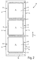
- FIG. 2 schematically a three-stage device according to the invention or a three-stage signal tower 8 is shown, again LED's 3 are provided.
- the numerous, arranged on a straight line LEDs 3 radiate in the longitudinal direction L or counter to this direction warning light, wherein the warning light according to the invention in the end face 2 of the respective radiating element 1 couples and exits at the radiating surfaces 4 in an advantageous manner / decoupled.
- the signal tower 8 advantageously has a frame 9 or a frame element 9, which is designed to accommodate all three stages or all three radiating elements 1 or radiating surfaces 4.
- the signal tower 8 has a multilayer structure, wherein, for example, an aluminum core printed circuit board is provided for forming a lower side of the frame 9.
- This aluminum core circuit board is preferably realized substantially of aluminum, on which e.g. an electrical insulation layer is arranged and on this in turn a Kupferleitbahn is arranged.
- the LED's 3 including further advantageous electronic components are arranged so that the Alukernleiterplatte on the one hand electrical printed circuit board and on the other hand by the advantageous metal / aluminum layer for heat dissipation of the waste heat of the LED's 3 is formed.
- the aluminum core circuit board is provided as a supporting frame element of the frame 9.
- the aluminum core printed circuit board carries or holds advantageous radiating elements 1 in an overlying layer, that is to say they are supported by means of a further frame layer or a cover element of the frame 9 or a cover frame element.
- the cover made of metal such as aluminum, so that both the bottom and the top of the frame 9 for the viewer appears uniform and an advantageous heat dissipation is realized by the frame 9.
- the frame or the aluminum core printed circuit board advantageously carries a control unit 10, which is used for driving the LED's 3 and the three different stages is formed.
- the signal tower 8 has the three different warning colors red, yellow and green.
- the frame 9 also recesses or slots 11 on the right and / or left side in FIG. 2 have, so not only the front and / or rear, but also right and left a radiating surface 4 according to the invention can be realized.
- the LED's 3 light in the radiating element 1 frontally couple and that not only on the large radiating surface 4 warning light is deflected by means of advantageous scattering means, but also warning light to the two end faces, where no LEDs 3 are arranged, light is coupled out and thus this as well Radiating surfaces 4 are realized.
- a modular signal tower 8 is realized with corresponding plate-shaped radiating elements 1, wherein the individual stages or warning light units can be connected together in an advantageous manner releasably connectable and released again.
- an electronic unit or control unit 10 or the like in a separate control module, which is designed to control or operate the respective individual warning light modules or radiating elements 1.
- the radiating elements 1 may be both plate-shaped and cylindrical, cuboidal or other multi-dimensional shapes.
- FIG. 3a should be a variant illustrate, wherein the scattering means is provided as a diffuser surface 4 or radiating surface 4, which are both roughened, coated and thus on the outer surface or outside of the corresponding diffuser surface 4 and radiating surface 4 are arranged.
- a section 12 is provided which, for example, has a polished surface, so that here the light coupled in by the LED 3 remains within the emission element 1 due to the total reflection realized here, or is passed on through this section 12 to the surface 4 and decoupled there.
- the area with the radiating surface 4 for example, consist of a plastic material which has scattering particles or scattering bodies in the interior, so that the corresponding light of the LED 3 is deflected and coupled out.
- the emission element Plexiglas can be used, which in section 12 does not comprise scattering particles and has advantageous scattering particles in the region of the surface 4, which for example are distributed homogeneously within the plexiglass or the like. This also results in a homogeneous appearance of the radiating surface 4 or device according to the invention.
- FIG. 3b shows a variant, wherein a portion or a region 19 is formed as a roughened or coated inside / - area.
- the region 19 is formed as an inner layer or structure 19 which encloses the (in FIG. 3b only indicated) warning light 6 deflects accordingly and deflects to the outside to the radiating surface 4.
- the Anrauung or coating can for example be realized in that the radiating element 1 is made in two parts, wherein an inner part 13 and an outer part 14, which is formed in a hollow cylinder, sandblasted in a defined surface, acid etched or covered with a diffuser layer. Also, the radiating element 1 can be formed as an injection molded part. It has been shown in first experiments that generated by a (slightly) rough surface of an injection molding tool, a diffuser surface, which advantageously the warning light 6 can be scattered or deflected. This is a particularly economically favorable variant according to the invention.
- a reflection or scattering of the warning light is realized according to the invention.
- an inner oblique surface 16 is generated, at which the warning light is scattered or deflected accordingly, so that in this area laterally the radiating surface 4 is generated according to the invention.
- point-like inner scattering surfaces or scattering sections 17 can be generated, which laterally deflect the corresponding warning light and decouple it according to the invention.
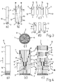
- FIG. 4 shows various embodiments with a cylindrical shaped luminous body or a cylindrical signal tower 8 according to the invention.
- FIG. 4a shows a single-stage signal tower 8, wherein the radiating element 1, however, has a radiating surface 4 and between the radiating surface 4 and the LEDs 3 in turn a section 12 is arranged.
- the section 12 in turn has a polished surface and passes the light on.
- a Vorschaltoptik 17 and a lens system 17 or the like is provided, which the generated by the LED's 3 (in the FIGS. 4b and 4c merely indicated) warning light 6 can be guided or guided in an advantageous manner and can be coupled into the end face according to the invention, so that the coupling is improved in the radiating element 1.
- each layer or each ring has a common warning light color.
- the front side annular LED's 3 are the same color, so that these according to the schematic plan view in FIG. 4d each annulus a common warning light (in the FIGS. 4b and 4c only as indicated warning light 6) einkoppeln in the radiating element 1 and decoupled by advantageous deflection or scattering within the ring or the layer / structure 19, the corresponding warning light 6 at different sections or areas 4.
- each warning light color is assigned a defined emission area 4 in each case. That is, in the longitudinal direction L different radiating surfaces 4 are provided, which are each provided for coupling out differently colored light 6.
- the warning light units is designed as a single unit / element.
- FIG 4c a correspondingly modular, multi-level signal tower 8 shown schematically.
- the individual modules 18 can be mechanically connected without a closer representation and can also be optically coupled together in the connected state, so that the light line is optically coupled or connected by a module 18 to an adjacent module 18.
- a layer can be provided, which shines red, for example, in operation and not only extends over a single section or a single module 18 in the longitudinal direction, but in the variants of Figures 4b or 4c extends over a plurality of modules 18 or even substantially over the entire length of the signal tower 8, ie over the entire length of the respective filament or the common unit or all modules 18.
- a running light operation of the ring-shaped LED's for the signaling of Be an advantage.
- an operating state warning lighting device can be realized, which not only has a plate-like or tile-like structure (cf. FIGS. 1 and 2 ) can be realized, but it can also be novel cylindrical signal columns 8 according to the variants of FIG. 4 be realized as a warning light stick or the like.
- This warning light rod can be in the off state (slightly) milky or cloudy or completely or almost completely transparent, so that it is very inconspicuous or less noticeable.
- a device according to the invention also with other or numerous other devices in an advantageous electronic signaling device network with each other (wireless) connected or operated.
- one or more LEDs or the like, but also at least one laser for generating visible warning light 6 or laser light can be provided for a warning light unit 1, 4 or a module 18 as light source / light sources.
Landscapes
- Physics & Mathematics (AREA)
- General Physics & Mathematics (AREA)
- Optics & Photonics (AREA)
- Engineering & Computer Science (AREA)
- General Engineering & Computer Science (AREA)
- Theoretical Computer Science (AREA)
- Electromagnetism (AREA)
- Illuminated Signs And Luminous Advertising (AREA)
- Non-Portable Lighting Devices Or Systems Thereof (AREA)
- Led Device Packages (AREA)
- Audible And Visible Signals (AREA)
Applications Claiming Priority (1)
| Application Number | Priority Date | Filing Date | Title |
|---|---|---|---|
| DE102013000336.9A DE102013000336A1 (de) | 2013-01-11 | 2013-01-11 | "Betriebszustandswarnleuchtvorrichtung" |
Publications (3)
| Publication Number | Publication Date |
|---|---|
| EP2762933A2 EP2762933A2 (de) | 2014-08-06 |
| EP2762933A3 EP2762933A3 (de) | 2014-10-15 |
| EP2762933B1 true EP2762933B1 (de) | 2016-11-09 |
Family
ID=49886564
Family Applications (1)
| Application Number | Title | Priority Date | Filing Date |
|---|---|---|---|
| EP13005811.8A Active EP2762933B1 (de) | 2013-01-11 | 2013-12-13 | "Betriebszustandswarnvorrichtung" |
Country Status (5)
| Country | Link |
|---|---|
| US (1) | US9619978B2 (enExample) |
| EP (1) | EP2762933B1 (enExample) |
| JP (1) | JP2015181086A (enExample) |
| CN (1) | CN103927832B (enExample) |
| DE (1) | DE102013000336A1 (enExample) |
Families Citing this family (3)
| Publication number | Priority date | Publication date | Assignee | Title |
|---|---|---|---|---|
| MX2018012627A (es) * | 2016-04-15 | 2019-08-05 | Emerson Climate Technologies | Sistema y metodo para desplegar mensajes en un formato columna a columna por medio de un arreglo de leds conectados a un circuito de un compresor. |
| US10312798B2 (en) | 2016-04-15 | 2019-06-04 | Emerson Electric Co. | Power factor correction circuits and methods including partial power factor correction operation for boost and buck power converters |
| DE102018001099B4 (de) * | 2018-02-10 | 2019-09-05 | Diehl Aerospace Gmbh | Flächenleuchte, Herstellungsverfahren und Innenraumabschnitt |
Citations (1)
| Publication number | Priority date | Publication date | Assignee | Title |
|---|---|---|---|---|
| US20120069595A1 (en) * | 2010-09-22 | 2012-03-22 | Anthony Catalano | Linear illumination devices |
Family Cites Families (18)
| Publication number | Priority date | Publication date | Assignee | Title |
|---|---|---|---|---|
| US6712481B2 (en) * | 1995-06-27 | 2004-03-30 | Solid State Opto Limited | Light emitting panel assemblies |
| TW514709B (en) * | 2000-05-04 | 2002-12-21 | Koninkl Philips Electronics Nv | Illumination system and display device |
| EP2244005A1 (en) * | 2001-12-05 | 2010-10-27 | Rambus International Ltd | Transreflector system |
| US7384988B2 (en) * | 2003-08-26 | 2008-06-10 | Union College | Method and device for fabricating aerogels and aerogel monoliths obtained thereby |
| ES2552252T3 (es) * | 2004-03-23 | 2015-11-26 | Boston Scientific Limited | Sistema de visualización in vivo |
| FR2869975B1 (fr) * | 2004-05-04 | 2006-06-16 | Schneider Electric Ind Sas | Colonne de signalisation verrouillable |
| JP4089692B2 (ja) * | 2004-09-02 | 2008-05-28 | 株式会社パトライト | レンズ部品、信号表示灯用表示ユニットおよび信号表示灯 |
| DE102004063574A1 (de) * | 2004-12-30 | 2006-07-13 | Osram Opto Semiconductors Gmbh | Leuchtvorrichtung mit mehreren Halbleiterlichtquellen |
| WO2007083805A1 (ja) * | 2006-01-23 | 2007-07-26 | Fujifilm Corporation | 面状照明装置 |
| DE202007005495U1 (de) | 2007-04-13 | 2007-08-30 | Werma Signaltechnik Gmbh + Co. Kg | Warnleuchtsäule |
| US7780330B2 (en) * | 2007-05-16 | 2010-08-24 | Rohm And Haas Electronics Materials Llc | Elongated illuminators configuration for LCD displays |
| DE102007054206A1 (de) * | 2007-10-15 | 2009-04-16 | Harald Hofmann | LED-Lampe mit Diffusor |
| US9052416B2 (en) * | 2008-11-18 | 2015-06-09 | Cree, Inc. | Ultra-high efficacy semiconductor light emitting devices |
| TW201024626A (en) * | 2008-12-19 | 2010-07-01 | Aegis Sports Inc | Light emitting strip structure having light guide effect |
| US7911692B2 (en) * | 2009-07-03 | 2011-03-22 | Seiko Epson Corporation | Screen and projection system |
| CH703004A1 (de) * | 2010-04-30 | 2011-10-31 | Tipper Tie Alpina Gmbh | Warnleuchte an einer Lebensmittel verarbeitenden Maschine. |
| JP5719638B2 (ja) * | 2011-03-02 | 2015-05-20 | 日東光学株式会社 | 光源装飾体および照明装置 |
| JP5645078B2 (ja) * | 2011-03-30 | 2014-12-24 | 株式会社パトライト | 発光装置 |
-
2013
- 2013-01-11 DE DE102013000336.9A patent/DE102013000336A1/de not_active Withdrawn
- 2013-12-13 EP EP13005811.8A patent/EP2762933B1/de active Active
-
2014
- 2014-01-09 US US14/151,799 patent/US9619978B2/en active Active
- 2014-01-10 JP JP2014003414A patent/JP2015181086A/ja active Pending
- 2014-01-13 CN CN201410076294.6A patent/CN103927832B/zh active Active
Patent Citations (1)
| Publication number | Priority date | Publication date | Assignee | Title |
|---|---|---|---|---|
| US20120069595A1 (en) * | 2010-09-22 | 2012-03-22 | Anthony Catalano | Linear illumination devices |
Also Published As
| Publication number | Publication date |
|---|---|
| JP2015181086A (ja) | 2015-10-15 |
| US20140197961A1 (en) | 2014-07-17 |
| EP2762933A3 (de) | 2014-10-15 |
| CN103927832A (zh) | 2014-07-16 |
| US9619978B2 (en) | 2017-04-11 |
| EP2762933A2 (de) | 2014-08-06 |
| DE102013000336A1 (de) | 2014-07-17 |
| CN103927832B (zh) | 2018-04-27 |
Similar Documents
| Publication | Publication Date | Title |
|---|---|---|
| EP2204604B1 (de) | Leuchte | |
| EP1301917B1 (de) | Passives strahloptik-modul, insbesondere zur verwendung mit leuchtdioden | |
| DE102016110054B4 (de) | Beleuchtungseinrichtung und Interieurteil für ein Fahrzeug | |
| DE102013108811A1 (de) | Leuchte, insbesondere Scheinwerfer | |
| EP2762933B1 (de) | "Betriebszustandswarnvorrichtung" | |
| DE112011101860T5 (de) | Außenspiegel-Anordnung mit einem Gehäuse umfassend eine Schaltkreisplatine mit einer Mehrzahl an lichtemittierenden Dioden | |
| DE102020107734A1 (de) | Leuchteinheit für eine Leuchtvorrichtung eines Kraftfahrzeugs und eine Leuchtvorrichtung mit der Leuchteinheit | |
| DE10242441A1 (de) | Leuchte | |
| EP3540294A1 (de) | Kraftfahrzeuglichtmodul | |
| DE102005019018A1 (de) | Leuchte mit wenigstens einem Lichtleiter und mehreren Lichtquellen | |
| DE102013007856A1 (de) | Lichtleitkörper und Leuchtvorrichtung mit dem Lichtleitkörper | |
| DE19835922A1 (de) | Optische Anzeigevorrichtung | |
| EP2982903B1 (de) | Leuchtenanordnung und damit ausgestattete leuchtvorrichtung | |
| EP3274627B1 (de) | Signalisierungsvorrichtung für befehls- und/oder meldegeräte | |
| DE102019134630A1 (de) | Beleuchtbares Bauteil einer Innenraumverkleidung und Kraftfahrzeug | |
| AT509563B1 (de) | Leuchte mit lichtausrichtungselementen | |
| EP2201414B1 (de) | Leuchtobjekt | |
| DE102018218441A1 (de) | Flächenleuchtelement und Innenausstattungselement für ein Kraftfahrzeug mit einem Flächenleuchtelement | |
| DE102009007854B4 (de) | Befehlsgerät mit hinterleuchteter Handhabe | |
| EP2796793B1 (de) | Dunstabzugshaube | |
| AT511756B1 (de) | Schild | |
| WO2007033864A1 (de) | Optische anzeige zur erzeugung eines optischen signals | |
| DE202008008308U1 (de) | Leuchtvorrichtung | |
| DE102017110767A1 (de) | Optisches system für dekoratives beleuchtungselement für innen- und aussenleuchten | |
| DE202006006874U1 (de) | Leuchte mit einem leuchtenden Element |
Legal Events
| Date | Code | Title | Description |
|---|---|---|---|
| PUAI | Public reference made under article 153(3) epc to a published international application that has entered the european phase |
Free format text: ORIGINAL CODE: 0009012 |
|
| 17P | Request for examination filed |
Effective date: 20131213 |
|
| AK | Designated contracting states |
Kind code of ref document: A2 Designated state(s): AL AT BE BG CH CY CZ DE DK EE ES FI FR GB GR HR HU IE IS IT LI LT LU LV MC MK MT NL NO PL PT RO RS SE SI SK SM TR |
|
| AX | Request for extension of the european patent |
Extension state: BA ME |
|
| PUAL | Search report despatched |
Free format text: ORIGINAL CODE: 0009013 |
|
| AK | Designated contracting states |
Kind code of ref document: A3 Designated state(s): AL AT BE BG CH CY CZ DE DK EE ES FI FR GB GR HR HU IE IS IT LI LT LU LV MC MK MT NL NO PL PT RO RS SE SI SK SM TR |
|
| AX | Request for extension of the european patent |
Extension state: BA ME |
|
| RIC1 | Information provided on ipc code assigned before grant |
Ipc: G02B 6/00 20060101AFI20140905BHEP |
|
| R17P | Request for examination filed (corrected) |
Effective date: 20150220 |
|
| RBV | Designated contracting states (corrected) |
Designated state(s): AL AT BE BG CH CY CZ DE DK EE ES FI FR GB GR HR HU IE IS IT LI LT LU LV MC MK MT NL NO PL PT RO RS SE SI SK SM TR |
|
| 17Q | First examination report despatched |
Effective date: 20151013 |
|
| GRAP | Despatch of communication of intention to grant a patent |
Free format text: ORIGINAL CODE: EPIDOSNIGR1 |
|
| INTG | Intention to grant announced |
Effective date: 20160607 |
|
| GRAJ | Information related to disapproval of communication of intention to grant by the applicant or resumption of examination proceedings by the epo deleted |
Free format text: ORIGINAL CODE: EPIDOSDIGR1 |
|
| GRAP | Despatch of communication of intention to grant a patent |
Free format text: ORIGINAL CODE: EPIDOSNIGR1 |
|
| INTG | Intention to grant announced |
Effective date: 20160721 |
|
| GRAS | Grant fee paid |
Free format text: ORIGINAL CODE: EPIDOSNIGR3 |
|
| GRAA | (expected) grant |
Free format text: ORIGINAL CODE: 0009210 |
|
| AK | Designated contracting states |
Kind code of ref document: B1 Designated state(s): AL AT BE BG CH CY CZ DE DK EE ES FI FR GB GR HR HU IE IS IT LI LT LU LV MC MK MT NL NO PL PT RO RS SE SI SK SM TR |
|
| REG | Reference to a national code |
Ref country code: GB Ref legal event code: FG4D Free format text: NOT ENGLISH |
|
| REG | Reference to a national code |
Ref country code: AT Ref legal event code: REF Ref document number: 844443 Country of ref document: AT Kind code of ref document: T Effective date: 20161115 Ref country code: CH Ref legal event code: EP |
|
| REG | Reference to a national code |
Ref country code: IE Ref legal event code: FG4D Free format text: LANGUAGE OF EP DOCUMENT: GERMAN |
|
| REG | Reference to a national code |
Ref country code: DE Ref legal event code: R096 Ref document number: 502013005262 Country of ref document: DE |
|
| REG | Reference to a national code |
Ref country code: FR Ref legal event code: PLFP Year of fee payment: 4 |
|
| PG25 | Lapsed in a contracting state [announced via postgrant information from national office to epo] |
Ref country code: LV Free format text: LAPSE BECAUSE OF FAILURE TO SUBMIT A TRANSLATION OF THE DESCRIPTION OR TO PAY THE FEE WITHIN THE PRESCRIBED TIME-LIMIT Effective date: 20161109 |
|
| REG | Reference to a national code |
Ref country code: LT Ref legal event code: MG4D |
|
| REG | Reference to a national code |
Ref country code: NL Ref legal event code: MP Effective date: 20161109 |
|
| PG25 | Lapsed in a contracting state [announced via postgrant information from national office to epo] |
Ref country code: NO Free format text: LAPSE BECAUSE OF FAILURE TO SUBMIT A TRANSLATION OF THE DESCRIPTION OR TO PAY THE FEE WITHIN THE PRESCRIBED TIME-LIMIT Effective date: 20170209 Ref country code: SE Free format text: LAPSE BECAUSE OF FAILURE TO SUBMIT A TRANSLATION OF THE DESCRIPTION OR TO PAY THE FEE WITHIN THE PRESCRIBED TIME-LIMIT Effective date: 20161109 Ref country code: GR Free format text: LAPSE BECAUSE OF FAILURE TO SUBMIT A TRANSLATION OF THE DESCRIPTION OR TO PAY THE FEE WITHIN THE PRESCRIBED TIME-LIMIT Effective date: 20170210 Ref country code: LT Free format text: LAPSE BECAUSE OF FAILURE TO SUBMIT A TRANSLATION OF THE DESCRIPTION OR TO PAY THE FEE WITHIN THE PRESCRIBED TIME-LIMIT Effective date: 20161109 Ref country code: NL Free format text: LAPSE BECAUSE OF FAILURE TO SUBMIT A TRANSLATION OF THE DESCRIPTION OR TO PAY THE FEE WITHIN THE PRESCRIBED TIME-LIMIT Effective date: 20161109 |
|
| PG25 | Lapsed in a contracting state [announced via postgrant information from national office to epo] |
Ref country code: IS Free format text: LAPSE BECAUSE OF FAILURE TO SUBMIT A TRANSLATION OF THE DESCRIPTION OR TO PAY THE FEE WITHIN THE PRESCRIBED TIME-LIMIT Effective date: 20170309 Ref country code: RS Free format text: LAPSE BECAUSE OF FAILURE TO SUBMIT A TRANSLATION OF THE DESCRIPTION OR TO PAY THE FEE WITHIN THE PRESCRIBED TIME-LIMIT Effective date: 20161109 Ref country code: PT Free format text: LAPSE BECAUSE OF FAILURE TO SUBMIT A TRANSLATION OF THE DESCRIPTION OR TO PAY THE FEE WITHIN THE PRESCRIBED TIME-LIMIT Effective date: 20170309 Ref country code: ES Free format text: LAPSE BECAUSE OF FAILURE TO SUBMIT A TRANSLATION OF THE DESCRIPTION OR TO PAY THE FEE WITHIN THE PRESCRIBED TIME-LIMIT Effective date: 20161109 Ref country code: BE Free format text: LAPSE BECAUSE OF NON-PAYMENT OF DUE FEES Effective date: 20161231 Ref country code: PL Free format text: LAPSE BECAUSE OF FAILURE TO SUBMIT A TRANSLATION OF THE DESCRIPTION OR TO PAY THE FEE WITHIN THE PRESCRIBED TIME-LIMIT Effective date: 20161109 Ref country code: HR Free format text: LAPSE BECAUSE OF FAILURE TO SUBMIT A TRANSLATION OF THE DESCRIPTION OR TO PAY THE FEE WITHIN THE PRESCRIBED TIME-LIMIT Effective date: 20161109 Ref country code: FI Free format text: LAPSE BECAUSE OF FAILURE TO SUBMIT A TRANSLATION OF THE DESCRIPTION OR TO PAY THE FEE WITHIN THE PRESCRIBED TIME-LIMIT Effective date: 20161109 |
|
| PG25 | Lapsed in a contracting state [announced via postgrant information from national office to epo] |
Ref country code: CZ Free format text: LAPSE BECAUSE OF FAILURE TO SUBMIT A TRANSLATION OF THE DESCRIPTION OR TO PAY THE FEE WITHIN THE PRESCRIBED TIME-LIMIT Effective date: 20161109 Ref country code: SK Free format text: LAPSE BECAUSE OF FAILURE TO SUBMIT A TRANSLATION OF THE DESCRIPTION OR TO PAY THE FEE WITHIN THE PRESCRIBED TIME-LIMIT Effective date: 20161109 Ref country code: EE Free format text: LAPSE BECAUSE OF FAILURE TO SUBMIT A TRANSLATION OF THE DESCRIPTION OR TO PAY THE FEE WITHIN THE PRESCRIBED TIME-LIMIT Effective date: 20161109 Ref country code: DK Free format text: LAPSE BECAUSE OF FAILURE TO SUBMIT A TRANSLATION OF THE DESCRIPTION OR TO PAY THE FEE WITHIN THE PRESCRIBED TIME-LIMIT Effective date: 20161109 Ref country code: RO Free format text: LAPSE BECAUSE OF FAILURE TO SUBMIT A TRANSLATION OF THE DESCRIPTION OR TO PAY THE FEE WITHIN THE PRESCRIBED TIME-LIMIT Effective date: 20161109 |
|
| REG | Reference to a national code |
Ref country code: CH Ref legal event code: PL |
|
| REG | Reference to a national code |
Ref country code: DE Ref legal event code: R097 Ref document number: 502013005262 Country of ref document: DE |
|
| PG25 | Lapsed in a contracting state [announced via postgrant information from national office to epo] |
Ref country code: BG Free format text: LAPSE BECAUSE OF FAILURE TO SUBMIT A TRANSLATION OF THE DESCRIPTION OR TO PAY THE FEE WITHIN THE PRESCRIBED TIME-LIMIT Effective date: 20170209 Ref country code: SM Free format text: LAPSE BECAUSE OF FAILURE TO SUBMIT A TRANSLATION OF THE DESCRIPTION OR TO PAY THE FEE WITHIN THE PRESCRIBED TIME-LIMIT Effective date: 20161109 |
|
| PLBE | No opposition filed within time limit |
Free format text: ORIGINAL CODE: 0009261 |
|
| STAA | Information on the status of an ep patent application or granted ep patent |
Free format text: STATUS: NO OPPOSITION FILED WITHIN TIME LIMIT |
|
| PG25 | Lapsed in a contracting state [announced via postgrant information from national office to epo] |
Ref country code: MC Free format text: LAPSE BECAUSE OF FAILURE TO SUBMIT A TRANSLATION OF THE DESCRIPTION OR TO PAY THE FEE WITHIN THE PRESCRIBED TIME-LIMIT Effective date: 20161109 |
|
| REG | Reference to a national code |
Ref country code: IE Ref legal event code: MM4A |
|
| 26N | No opposition filed |
Effective date: 20170810 |
|
| PG25 | Lapsed in a contracting state [announced via postgrant information from national office to epo] |
Ref country code: LU Free format text: LAPSE BECAUSE OF NON-PAYMENT OF DUE FEES Effective date: 20161213 Ref country code: LI Free format text: LAPSE BECAUSE OF NON-PAYMENT OF DUE FEES Effective date: 20161231 Ref country code: CH Free format text: LAPSE BECAUSE OF NON-PAYMENT OF DUE FEES Effective date: 20161231 |
|
| PG25 | Lapsed in a contracting state [announced via postgrant information from national office to epo] |
Ref country code: SI Free format text: LAPSE BECAUSE OF FAILURE TO SUBMIT A TRANSLATION OF THE DESCRIPTION OR TO PAY THE FEE WITHIN THE PRESCRIBED TIME-LIMIT Effective date: 20161109 Ref country code: IE Free format text: LAPSE BECAUSE OF NON-PAYMENT OF DUE FEES Effective date: 20161213 |
|
| REG | Reference to a national code |
Ref country code: FR Ref legal event code: PLFP Year of fee payment: 5 |
|
| REG | Reference to a national code |
Ref country code: BE Ref legal event code: MM Effective date: 20161231 |
|
| PG25 | Lapsed in a contracting state [announced via postgrant information from national office to epo] |
Ref country code: HU Free format text: LAPSE BECAUSE OF FAILURE TO SUBMIT A TRANSLATION OF THE DESCRIPTION OR TO PAY THE FEE WITHIN THE PRESCRIBED TIME-LIMIT; INVALID AB INITIO Effective date: 20131213 |
|
| PG25 | Lapsed in a contracting state [announced via postgrant information from national office to epo] |
Ref country code: CY Free format text: LAPSE BECAUSE OF FAILURE TO SUBMIT A TRANSLATION OF THE DESCRIPTION OR TO PAY THE FEE WITHIN THE PRESCRIBED TIME-LIMIT Effective date: 20161109 Ref country code: MK Free format text: LAPSE BECAUSE OF FAILURE TO SUBMIT A TRANSLATION OF THE DESCRIPTION OR TO PAY THE FEE WITHIN THE PRESCRIBED TIME-LIMIT Effective date: 20161109 |
|
| PG25 | Lapsed in a contracting state [announced via postgrant information from national office to epo] |
Ref country code: MT Free format text: LAPSE BECAUSE OF FAILURE TO SUBMIT A TRANSLATION OF THE DESCRIPTION OR TO PAY THE FEE WITHIN THE PRESCRIBED TIME-LIMIT Effective date: 20161109 |
|
| PG25 | Lapsed in a contracting state [announced via postgrant information from national office to epo] |
Ref country code: TR Free format text: LAPSE BECAUSE OF FAILURE TO SUBMIT A TRANSLATION OF THE DESCRIPTION OR TO PAY THE FEE WITHIN THE PRESCRIBED TIME-LIMIT Effective date: 20161109 |
|
| REG | Reference to a national code |
Ref country code: AT Ref legal event code: MM01 Ref document number: 844443 Country of ref document: AT Kind code of ref document: T Effective date: 20181213 |
|
| PG25 | Lapsed in a contracting state [announced via postgrant information from national office to epo] |
Ref country code: AT Free format text: LAPSE BECAUSE OF NON-PAYMENT OF DUE FEES Effective date: 20181213 |
|
| PG25 | Lapsed in a contracting state [announced via postgrant information from national office to epo] |
Ref country code: AL Free format text: LAPSE BECAUSE OF FAILURE TO SUBMIT A TRANSLATION OF THE DESCRIPTION OR TO PAY THE FEE WITHIN THE PRESCRIBED TIME-LIMIT Effective date: 20161109 |
|
| REG | Reference to a national code |
Ref country code: DE Ref legal event code: R082 Ref document number: 502013005262 Country of ref document: DE Representative=s name: RAVENSPAT PATENTANWAELTE PARTNERSCHAFT MBB, DE |
|
| PGFP | Annual fee paid to national office [announced via postgrant information from national office to epo] |
Ref country code: GB Payment date: 20251218 Year of fee payment: 13 |
|
| PGFP | Annual fee paid to national office [announced via postgrant information from national office to epo] |
Ref country code: FR Payment date: 20251218 Year of fee payment: 13 |
|
| PGFP | Annual fee paid to national office [announced via postgrant information from national office to epo] |
Ref country code: DE Payment date: 20251222 Year of fee payment: 13 |
|
| PGFP | Annual fee paid to national office [announced via postgrant information from national office to epo] |
Ref country code: IT Payment date: 20251231 Year of fee payment: 13 |