EP2762222A1 - Lufttrennvorrichtung mit Axialabstützung eines zweischaligen Gehäuses - Google Patents
Lufttrennvorrichtung mit Axialabstützung eines zweischaligen Gehäuses Download PDFInfo
- Publication number
- EP2762222A1 EP2762222A1 EP14152362.1A EP14152362A EP2762222A1 EP 2762222 A1 EP2762222 A1 EP 2762222A1 EP 14152362 A EP14152362 A EP 14152362A EP 2762222 A1 EP2762222 A1 EP 2762222A1
- Authority
- EP
- European Patent Office
- Prior art keywords
- axial support
- tubesheet
- support assembly
- fiber bundle
- bundle
- Prior art date
- Legal status (The legal status is an assumption and is not a legal conclusion. Google has not performed a legal analysis and makes no representation as to the accuracy of the status listed.)
- Granted
Links
- 238000000926 separation method Methods 0.000 title abstract description 8
- 239000000835 fiber Substances 0.000 claims abstract description 71
- 230000003319 supportive effect Effects 0.000 claims abstract description 17
- 230000008878 coupling Effects 0.000 claims description 19
- 238000010168 coupling process Methods 0.000 claims description 19
- 238000005859 coupling reaction Methods 0.000 claims description 19
- 239000004593 Epoxy Substances 0.000 claims description 7
- 229910052751 metal Inorganic materials 0.000 claims description 6
- 239000002184 metal Substances 0.000 claims description 6
- 238000003780 insertion Methods 0.000 claims description 3
- 230000037431 insertion Effects 0.000 claims description 3
- 239000012510 hollow fiber Substances 0.000 abstract description 17
- 239000012528 membrane Substances 0.000 abstract description 17
- QVGXLLKOCUKJST-UHFFFAOYSA-N atomic oxygen Chemical compound [O] QVGXLLKOCUKJST-UHFFFAOYSA-N 0.000 abstract description 9
- 239000001301 oxygen Substances 0.000 abstract description 9
- 229910052760 oxygen Inorganic materials 0.000 abstract description 9
- 239000012530 fluid Substances 0.000 abstract description 4
- 241000769223 Thenea Species 0.000 description 10
- IJGRMHOSHXDMSA-UHFFFAOYSA-N Atomic nitrogen Chemical compound N#N IJGRMHOSHXDMSA-UHFFFAOYSA-N 0.000 description 8
- 239000002828 fuel tank Substances 0.000 description 8
- 238000000034 method Methods 0.000 description 8
- 238000004382 potting Methods 0.000 description 8
- 239000007789 gas Substances 0.000 description 7
- 238000004891 communication Methods 0.000 description 4
- 229910052757 nitrogen Inorganic materials 0.000 description 4
- 230000006835 compression Effects 0.000 description 3
- 238000007906 compression Methods 0.000 description 3
- 238000005336 cracking Methods 0.000 description 3
- 229910052782 aluminium Inorganic materials 0.000 description 2
- XAGFODPZIPBFFR-UHFFFAOYSA-N aluminium Chemical compound [Al] XAGFODPZIPBFFR-UHFFFAOYSA-N 0.000 description 2
- 239000011248 coating agent Substances 0.000 description 2
- 238000000576 coating method Methods 0.000 description 2
- 238000013461 design Methods 0.000 description 2
- 238000004880 explosion Methods 0.000 description 2
- 239000000446 fuel Substances 0.000 description 2
- 238000012423 maintenance Methods 0.000 description 2
- 238000004519 manufacturing process Methods 0.000 description 2
- 229920000642 polymer Polymers 0.000 description 2
- 230000008569 process Effects 0.000 description 2
- 239000007787 solid Substances 0.000 description 2
- 201000008217 Aggressive systemic mastocytosis Diseases 0.000 description 1
- 239000004642 Polyimide Substances 0.000 description 1
- 230000009286 beneficial effect Effects 0.000 description 1
- 238000005266 casting Methods 0.000 description 1
- 238000010276 construction Methods 0.000 description 1
- 230000001934 delay Effects 0.000 description 1
- 238000009792 diffusion process Methods 0.000 description 1
- 238000005516 engineering process Methods 0.000 description 1
- 239000002360 explosive Substances 0.000 description 1
- 238000001914 filtration Methods 0.000 description 1
- 239000011261 inert gas Substances 0.000 description 1
- 238000001471 micro-filtration Methods 0.000 description 1
- 239000000203 mixture Substances 0.000 description 1
- 238000012986 modification Methods 0.000 description 1
- 230000004048 modification Effects 0.000 description 1
- 238000004806 packaging method and process Methods 0.000 description 1
- 229920001721 polyimide Polymers 0.000 description 1
- 238000004080 punching Methods 0.000 description 1
- 230000009467 reduction Effects 0.000 description 1
- 229910001220 stainless steel Inorganic materials 0.000 description 1
- 239000010935 stainless steel Substances 0.000 description 1
- 229920001187 thermosetting polymer Polymers 0.000 description 1
- 238000009966 trimming Methods 0.000 description 1
- 238000000108 ultra-filtration Methods 0.000 description 1
- 238000003466 welding Methods 0.000 description 1
- 238000009736 wetting Methods 0.000 description 1
Images


Classifications
-
- B—PERFORMING OPERATIONS; TRANSPORTING
- B01—PHYSICAL OR CHEMICAL PROCESSES OR APPARATUS IN GENERAL
- B01D—SEPARATION
- B01D63/00—Apparatus in general for separation processes using semi-permeable membranes
- B01D63/02—Hollow fibre modules
- B01D63/021—Manufacturing thereof
-
- B—PERFORMING OPERATIONS; TRANSPORTING
- B01—PHYSICAL OR CHEMICAL PROCESSES OR APPARATUS IN GENERAL
- B01D—SEPARATION
- B01D63/00—Apparatus in general for separation processes using semi-permeable membranes
- B01D63/02—Hollow fibre modules
- B01D63/031—Two or more types of hollow fibres within one bundle or within one potting or tube-sheet
-
- B—PERFORMING OPERATIONS; TRANSPORTING
- B01—PHYSICAL OR CHEMICAL PROCESSES OR APPARATUS IN GENERAL
- B01D—SEPARATION
- B01D63/00—Apparatus in general for separation processes using semi-permeable membranes
- B01D63/02—Hollow fibre modules
- B01D63/021—Manufacturing thereof
- B01D63/022—Encapsulating hollow fibres
-
- B—PERFORMING OPERATIONS; TRANSPORTING
- B01—PHYSICAL OR CHEMICAL PROCESSES OR APPARATUS IN GENERAL
- B01D—SEPARATION
- B01D63/00—Apparatus in general for separation processes using semi-permeable membranes
- B01D63/02—Hollow fibre modules
- B01D63/021—Manufacturing thereof
- B01D63/0233—Manufacturing thereof forming the bundle
-
- B—PERFORMING OPERATIONS; TRANSPORTING
- B64—AIRCRAFT; AVIATION; COSMONAUTICS
- B64D—EQUIPMENT FOR FITTING IN OR TO AIRCRAFT; FLIGHT SUITS; PARACHUTES; ARRANGEMENTS OR MOUNTING OF POWER PLANTS OR PROPULSION TRANSMISSIONS IN AIRCRAFT
- B64D37/00—Arrangements in connection with fuel supply for power plant
- B64D37/32—Safety measures not otherwise provided for, e.g. preventing explosive conditions
-
- B—PERFORMING OPERATIONS; TRANSPORTING
- B01—PHYSICAL OR CHEMICAL PROCESSES OR APPARATUS IN GENERAL
- B01D—SEPARATION
- B01D2256/00—Main component in the product gas stream after treatment
- B01D2256/10—Nitrogen
-
- B—PERFORMING OPERATIONS; TRANSPORTING
- B01—PHYSICAL OR CHEMICAL PROCESSES OR APPARATUS IN GENERAL
- B01D—SEPARATION
- B01D2256/00—Main component in the product gas stream after treatment
- B01D2256/12—Oxygen
-
- B—PERFORMING OPERATIONS; TRANSPORTING
- B01—PHYSICAL OR CHEMICAL PROCESSES OR APPARATUS IN GENERAL
- B01D—SEPARATION
- B01D2313/00—Details relating to membrane modules or apparatus
- B01D2313/02—Specific tightening or locking mechanisms
- B01D2313/025—Specific membrane holders
-
- B—PERFORMING OPERATIONS; TRANSPORTING
- B01—PHYSICAL OR CHEMICAL PROCESSES OR APPARATUS IN GENERAL
- B01D—SEPARATION
- B01D2313/00—Details relating to membrane modules or apparatus
- B01D2313/21—Specific headers, end caps
-
- B—PERFORMING OPERATIONS; TRANSPORTING
- B01—PHYSICAL OR CHEMICAL PROCESSES OR APPARATUS IN GENERAL
- B01D—SEPARATION
- B01D2313/00—Details relating to membrane modules or apparatus
- B01D2313/23—Specific membrane protectors, e.g. sleeves or screens
-
- B—PERFORMING OPERATIONS; TRANSPORTING
- B01—PHYSICAL OR CHEMICAL PROCESSES OR APPARATUS IN GENERAL
- B01D—SEPARATION
- B01D2313/00—Details relating to membrane modules or apparatus
- B01D2313/56—Specific mechanisms for loading the membrane in a module
-
- B—PERFORMING OPERATIONS; TRANSPORTING
- B01—PHYSICAL OR CHEMICAL PROCESSES OR APPARATUS IN GENERAL
- B01D—SEPARATION
- B01D53/00—Separation of gases or vapours; Recovering vapours of volatile solvents from gases; Chemical or biological purification of waste gases, e.g. engine exhaust gases, smoke, fumes, flue gases, aerosols
- B01D53/22—Separation of gases or vapours; Recovering vapours of volatile solvents from gases; Chemical or biological purification of waste gases, e.g. engine exhaust gases, smoke, fumes, flue gases, aerosols by diffusion
-
- B—PERFORMING OPERATIONS; TRANSPORTING
- B01—PHYSICAL OR CHEMICAL PROCESSES OR APPARATUS IN GENERAL
- B01D—SEPARATION
- B01D63/00—Apparatus in general for separation processes using semi-permeable membranes
- B01D63/02—Hollow fibre modules
- B01D63/021—Manufacturing thereof
- B01D63/022—Encapsulating hollow fibres
- B01D63/0221—Encapsulating hollow fibres using a mould
-
- Y—GENERAL TAGGING OF NEW TECHNOLOGICAL DEVELOPMENTS; GENERAL TAGGING OF CROSS-SECTIONAL TECHNOLOGIES SPANNING OVER SEVERAL SECTIONS OF THE IPC; TECHNICAL SUBJECTS COVERED BY FORMER USPC CROSS-REFERENCE ART COLLECTIONS [XRACs] AND DIGESTS
- Y02—TECHNOLOGIES OR APPLICATIONS FOR MITIGATION OR ADAPTATION AGAINST CLIMATE CHANGE
- Y02T—CLIMATE CHANGE MITIGATION TECHNOLOGIES RELATED TO TRANSPORTATION
- Y02T50/00—Aeronautics or air transport
- Y02T50/40—Weight reduction
Definitions
- the present invention generally relates to gas generating systems, such as on-board inert gas generating systems (OBIGGS) and, more particularly, to air separation modules (ASM) for gas generating systems.
- OBIGGS on-board inert gas generating systems
- ASM air separation modules
- the Federal Aviation Agency has issued safety mandates requiring that all new and existing aircraft inert the fuel tank to prevent explosions.
- One accepted method of fuel tank inerting is the OBIGGS.
- Aircraft have used the OBIGGS to protect against fuel tank explosions by replacing the potentially explosive fuel vapor/air mixture above the fuel in the ullage space of the tanks with nitrogen enriched air (NEA).
- NAA nitrogen enriched air
- the ASM may be configured to receive air, such as bleed air, and to provide a NEA flow to inert the fuel tank and an oxygen enriched air (OEA) flow.
- OEA oxygen enriched air
- the OEA flow can be recaptured or vented overboard.
- the ASM can include a housing having an inlet to receive air (e.g. bleed air), a NEA outlet and an OEA outlet.
- the ASM may include a bundle of hollow fiber membranes positioned within the housing. At least one end of the fiber bundle may be cast or potted in what is commonly referred to as a tubesheet. More commonly, both ends of the fiber bundle may be so encapsulated with the tubesheet.
- the tubesheets may serve to hold the fibers in a fluid-tight relationship such that the NEA flow may be isolated from the OEA flow.
- An inner tube such as the inner tube described in US Patent Application 2010/0024649 A1 , may be included within the fiber bundle to provide axial support.
- the ASM utilizes membrane technology to separate oxygen from air.
- air may enter the housing through the inlet and pass through the bundle of hollow fiber membranes.
- Oxygen may be separated from the air flow due to diffusion through the fiber walls because the fiber walls may be more permeable to oxygen than to nitrogen.
- the NEA flow may be generated by the loss of oxygen via permeation through the fiber wall.
- the NEA flow may exit the housing through the NEA outlet and the OEA flow may exit through the OEA outlet.
- an NEA oxygen concentration of 12% or less is sufficient to inert the fuel tank.
- the amount of NEA flow may be the key performance metric. Higher NEA flow per size and weight of ASM translate into lower the OBIGGS size and weight. Further, it is desirable that the ASM have a long maintenance interval to reduce cost and delays associated with the servicing of the ASM.
- an apparatus for insertion into a housing structure having a housing shell comprises a potted bundle positionable within the housing structure, the potted bundle including a fiber bundle and at least one tubesheet; and an axial support assembly positioned around the potted bundle radially outward from the fiber bundle and radially inward from the housing shell when the apparatus is inserted into the housing structure.
- an apparatus for insertion into a housing structure comprises a fiber bundle having a plurality of hollow fiber membranes; a tubesheet in contact with the fiber bundle, the tubesheet including a support coupling groove; and two supportive elements positioned between the fiber bundle and the housing structure, each supportive element in contact with the support coupling groove.
- a method of supporting a fiber bundle comprises the steps of potting each end of the fiber bundle to provide a potted bundle having one tubesheet adjacent each end of the fiber bundle; positioning an axial support assembly around the potted bundle to form a supported fiber bundle assembly; securing portions of the supported fiber bundle assembly together; and positioning at least one o-ring in physical contact with the tubesheet.
- the present invention provides ASMs and methods for producing the same.
- Embodiments of the present invention may find beneficial use in industries such as the aerospace, gas separation, microfiltration, and ultrafiltration.
- Embodiments of the present invention may be useful in applications including OBIGGS for inerting fuel tanks.
- Embodiments of the present invention may be useful in any filtration or gas separation application including, but not limited to, OBIGGS for aircraft.
- the ASM 40 may include a housing structure 42, a fiber bundle 44, at least one tubesheet 46a, 46b (see Figures 2-3 ), and an axial support assembly 48.
- the housing structure 42 may include a housing shell 50, a first endcap 52 and a second endcap (not shown).
- the housing shell 50 may be cylindrical in shape.
- the first endcap 52 may be positioned adjacent a first end 54 of the shell 50 and the second endcap may be positioned adjacent a second end (not shown) of the shell 50.
- the first endcap 52 may include an inlet element 56.
- the inlet element 56 may be adapted to receive a supply of gas 58, such as a supply of bleed air.
- the inlet element 56 may be in flow communication with an aircraft engine (not shown).
- the inlet element 56 may be adapted such that during operation of the ASM 40 the supply of gas 58 may enter the ASM 40 through the inlet element 56.
- the housing shell 50 may include an outlet element 60, such as an oxygen enriched air (OEA) outlet.
- the outlet element 60 may be adapted such that during operation of the ASM 40 a supply of OEA 62 may exit the ASM 40 through the outlet element 60.
- the second endcap may include an outlet (not shown), such as a nitrogen enriched air (NEA) outlet.
- the NEA outlet may be adapted such that during operation of the ASM 40 a supply of NEA (not shown) may exit the ASM 40 through the NEA outlet.
- the NEA outlet may be in flow communication with an aircraft fuel tank (not shown).
- the housing structure 42 may comprise metal.
- the housing structure 42 may include 12-gauge stainless steel.
- the housing structure 42 may include aluminum.
- the housing structure 42 may be embedded on an aircraft (not shown).
- the housing structure 42 may be configured to enclose the fiber bundle 44, the tubesheets 46a, 46b and the axial support assembly 48.
- the fiber bundle 44 may be inserted into the housing structure 42.
- the fiber bundle 44 may include a plurality of hollow fiber membranes 64a, 64b, 64c.
- Hollow fiber membranes 64a, 64b, 64c are known in the art and may include polymers such as polyimide.
- Useful hollow fiber membranes 64a, 64b, 64c may include the membranes described in U.S. Patent Application No.12/641787 filed on 12/18/2009 , which is incorporated herein by reference.
- Each hollow fiber membrane 64a, 64b, 64c may include a bore (not shown) that extends in a fluid communication relationship through the tubesheets 46a, 46b.
- the tubesheets 46a, 46b are known in the art and may include polymers, such as thermoset polymers.
- Useful tubesheets 46a, 46b may include the filled epoxy tubesheets described in U.S. Patent No. 7,867,319 , which is incorporated herein by reference.
- Filled epoxy tubesheets may comprise an epoxy filled with a metal, such as aluminum flakes.
- the fiber bundle 44 may be potted such that one tubesheet 46a, 46b is positioned at or adjacent each end of the fiber bundle 44 forming a potted bundle 66 (see Figure 3 ).
- Each tubesheet 46a, 46b may include a face seal groove 68 and at least one radial seal groove 70a, 70b, 70c, 70d. Each seal groove 68, 70a, 70b, 70c, 70d may be configured to receive an o-ring 72a, 72b, 72c. During assembly of the ASM 42, the o-rings 72a, 72b, 72c may be positioned between the tubesheet 46a, 46b and the housing structure 42 to form fluid-tight compression seals so that when the supply of gas 58 passes through the housing structure 42, the ASM 40 can isolate the supply of NEA from the supply of OEA 62. Each tubesheet 46a, 46b also may include a support coupling groove 74a, 74b adapted to engage a portion of the axial support assembly 48.
- the axial support assembly 48 may be positioned around the fiber bundle 44.
- the axial support assembly 48 may be positioned radially inward from the housing shell 50 when the axial support assembly 48 is inserted into the housing structure 42 and radially outward from the fiber bundle 44. In other words, the axial support assembly 48 may be between the housing shell 50 and the fiber bundle 44.
- the axial support assembly 48 may be cylindrical.
- the inner diameter of the axial support assembly 48 may be greater than the outer diameter of the fiber bundle 44 to reduce damage to the hollow fiber membranes 64a, 64b, 64c due to contact with the axial support assembly 48.
- the inner diameter of the axial support assembly 48 may be at least about 1/16 inch greater than the outer diameter of the fiber bundle 44.
- the outer diameter of the axial support assembly 48 may be less than the inner diameter of the housing shell 50.
- the outer diameter of the axial support assembly 48 may be about 1/16 inch less than the inner diameter of the housing shell 50 to maintain flow while minimizing packaging.
- the axial support assembly 48 may comprise two supportive elements 76a and 76b configured to fit over the hollow-fiber section of the potted bundle 66 to form a supported fiber bundle assembly 78, as shown in Figures 2 and 3 .
- the supportive element 76a, 76b may be U-shaped or half circular shaped.
- the supportive element 76a, 76b may include a flow-through component 80a, 80b.
- the supportive element 76a, 76b also may include one tubesheet coupling component 82a, 82b, 82c, 82d positioned at each end of the flow-through component 80a, 80b.
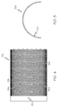
- the flow-through component 80a may include a plurality of openings 84a, 84b, 84c.
- the openings 84a, 84b, 84c may be adapted to provide fluid communication through the flow-through component 80a.
- a fluid such as the supply of OEA 62, may pass through the flow-through component 80a via the openings 84a, 84b, 84c during operation of the ASM 42.
- the openings 84a, 84b, 84c may be any shape.
- the shape of the opening 84a, 84b, 84c may include, but is not limited to, ovals, circles, squares and slots.
- the flow-through component 80a may comprise a rolled strip of a perforated plate and the openings 84a, 84b, 84c may comprise holes, such as 3/16 inch diameter holes on 1 ⁇ 4 inch staggered pitch, as shown in Figures 4 and 6 .
- the diameter of the holes may be between about 0.062 inches and about 0.750 inches.
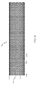
- the flow-through component 80a may comprise a rolled strip of slotted plate and the openings 84a, 84b may comprise a plurality of circumferentially spaced apart longitudinal slots, as shown in Figures 7-8 .
- the open area (combined area of the openings 84a, 84b, 84c) of the flow-through component 80a, 80b may vary with application and may be determined by the size and spacing of the openings 84a, 84b, 84c.
- the open area may be about 51 % of the flow-through component 80a, 80b.
- Pressure drop across the flow-through component 80a, 80b may be minimized and component strength may be maintained by adjusting the percentage of open area of the flow-through component 80a, 80b.
- the open area may be between about 20% and about 60% of the flow-through component 80a, 80b.
- the tubesheet coupling components 82a, 82b, 82c, 82d may provide collar-like structures on the ends of the flow-through component 80a, 80b.
- Each tubesheet coupling component 82a, 82b, 82c, 82d may comprise a strip of solid plate.
- the tubesheet coupling component 82a, 82b, 82c, 82d may be configured to engage the support coupling groove 74a, 74b of the tubesheet 46a, 46b.
- the axial support assembly 48 may be placed over the fiber bundle 44 while the bundle is being handled during the fabrication process (potting and coating stages).
- the tubesheet coupling component 82a, 82b, 82c, 82d of the axial support assembly 48 may be positioned in contact with the tubesheet 46a, 46b after the fiber bundle 44 is potted. Tubesheet cracking due to potting the axial support assembly 48 in conjunction with the fiber bundle 44 and integral with the tubesheet 46a, 46b may be eliminated. Tubesheet cracking resulting from differential thermal expansion of the tubesheet 46a, 46b and the axial support assembly 48 can be avoided. Also, the axial support assembly 48 provides rigidity for the fiber bundle 44 and prevents collapse of the fiber bundle 44 during normal operation.
- Tubesheet cracking is a potential failure mode because once cracked, air starts leaking through the cracks, bypassing the membrane and mixing with the NEA, and therefore the desired concentration of nitrogen cannot be achieved. Leakage through the tubesheet 46a, 46b results in a reduction in separation selectivity of the ASM 40 and drastically affects the ASM's overall performance.
- the tubesheet coupling components 82a, 82b, 82c, 82d may be trimmed to provide adjustability to the axial support assembly 48 should the fiber bundle 44 shrink during the manufacturing or in service.
- the tubesheet coupling components 82a, 82b, 82c, 82d may be trimmed to adjust the length of the axial support assembly 48.
- the fiber bundle 44 may be measured after potting and fiber shrinkage.
- the tubesheet coupling components 82a, 82b, 82c, 82d then may be trimmed to provide an axial support assembly 48 of the desired length.
- the tubesheet coupling component 82a, 82b, 82c, 82d may be welded to the flow-through component 80a, 80b.
- the tubesheet coupling component 82a, 82b, 82c, 82d may be integral to the flow-through component 80a, 80b.
- the supportive element 76a, 76b may be formed by starting with a solid plate and punching holes (openings 84a, 84b, 84c) in the center section. This single piece could be rolled into the U-shape (or half circular shape) and thus would be considered one-piece construction.
- two supportive elements 76a, 76b may be placed over the hollow-fiber section of the potted bundle 66 and secured together.
- the supportive elements 76a, 76b may be tack-welded along the longitudinal seam.
- hose clamps (not shown) or metal rings (not shown) may be used to secure the elements 76a, 76b of the axial support assembly 48 together.
- a more compact fiber bundle design may be achieved because there may be more room available within the fiber bundle 44 to pack extra hollow fiber membranes 64a, 64b, 64c.
- a 1 inch outside diameter tube consumes about 15% of the volume of a 6 inch outside diameter ASM 40 when placed within the fiber bundle 44.
- the additional hollow fiber membranes 64a, 64b, 64c allows for a higher surface area to be achieved which leads to higher product flow for a similar sized fiber bundle 44 with an internal axial support.
- the higher product flow for the fiber bundle 44 allows for the ASM 40 to be optimized for higher product flow while minimizing the spatial and weight impact on the OBIGGS.
- the method 300 may include a step 310 of potting each end of the fiber bundle 44 to provide a potted bundle 66 having one tubesheet 46a, 46b at each end of the fiber bundle 44.
- an axial support assembly 48 is positioned around the potted bundle 66 to form a supported fiber bundle assembly 78.
- portions of the supported fiber bundle assembly 78 are secured together.
- at least one o-ring is positioned in contact with each tubesheet 46a, 46b; and in step 350 the supported fiber bundle assembly 78 is inserted into a housing structure 42.
- the step 310 of potting each end of the fiber bundle 44 to provide a potted bundle 66 may include wetting the fiber bundle 44 with a first portion of preheated filled epoxy (not shown) and potting the fiber bundle 44 with a second portion of filled epoxy (not shown).
- the step 320 of positioning an axial support assembly 48 around the potted bundle 66 to form a supported fiber bundle assembly 78 may include adjusting the length of the axial support assembly 48 by trimming the tubesheet coupling components 82a, 82b, 82c, 82d so that the tubesheet coupling components 82a, 82b, 82c, 82d of the axial support assembly 48 engages the support coupling groove 74a, 74b of the tubesheet 46a, 46b.
- the step 330 of securing portions of the supported fiber bundle assembly 78 together may include tack welding the supportive elements 76a, 76b together.
- the step 330 of securing portions of the supported fiber bundle assembly 78 together may include securing the supportive elements 76a, 76b together with hose clamps (not shown).
- the step 330 of securing portions of the supported fiber bundle assembly 78 together may include positioning at least one metal ring (not shown) around the axial support assembly 48 to secure the supportive elements 76a, 76b together.
- the step 330 of securing portions of the supported fiber bundle assembly 78 together may include positioning three metal rings around the axial support assembly 48.
- the step 340 of positioning at least one o-ring in contact with each tubesheet 46a, 46b of the supported fiber bundle assembly 78 may include positioning the o-ring 72a, 72b, 72c in a radial seal groove 70a, 70b, 70c, 70d.
- the step 340 of positioning at least one o-ring in contact with each tubesheet 46a, 46b of the supported fiber bundle assembly 78 may include positioning the o-ring 72a, 72b, 72c in a face seal groove 70a, 70b, 70c, 70d.
- the step 340 of positioning at least one o-ring in contact with each tubesheet 46a, 46b may include positioning at least one o-ring in physical contact with the tubesheet 46a, 46b.
- the step 350 of inserting the supported fiber bundle assembly 78 into a housing structure 42 may include forming at least one fluid-tight compression seal between each tubesheet 46a, 46b and the housing structure 42.
- Each end of a fiber bundle 44 was potted separately (potting refers to the process of casting the end of the fibers with epoxy into a mold and cured to form the tubesheet 46a, 46b).
- the external axial support 48 was placed outside the potted bundle 66 to provide rigidity to the bundle.
- Radial o-rings were installed on the tubesheet 46a, 46b at both ends and the bundle was slid into an ASM housing shell 50.
- An o-ring 72a was also placed at each end of the tubesheet bundle to provide a face seal between the housing flanges and tubesheet bundle. Once the flanges were tightened against the face seal, the ASM assembly was complete.
- the axial support design was optimized for axial strength, stiffness for o-ring compression seal, and flow from the hollow fibers 64a, 64b, 64c to the oxygen outlet (OEA outlet).
- embodiments of the present invention can reduce the size and weight of the ASM 40 by incorporating the axial support assembly 48 outside the fiber bundle 44.
- the NEA flow can be increased by increasing the number of hollow fiber membranes 64a, 64b, 64c.
Applications Claiming Priority (1)
| Application Number | Priority Date | Filing Date | Title |
|---|---|---|---|
| US13/754,813 US9186628B2 (en) | 2013-01-30 | 2013-01-30 | Air separation module with clam shell axial support |
Publications (2)
| Publication Number | Publication Date |
|---|---|
| EP2762222A1 true EP2762222A1 (de) | 2014-08-06 |
| EP2762222B1 EP2762222B1 (de) | 2019-07-24 |
Family
ID=50028796
Family Applications (1)
| Application Number | Title | Priority Date | Filing Date |
|---|---|---|---|
| EP14152362.1A Active EP2762222B1 (de) | 2013-01-30 | 2014-01-23 | Lufttrennvorrichtung mit Axialabstützung durch Hülse zum Klemmen |
Country Status (2)
| Country | Link |
|---|---|
| US (1) | US9186628B2 (de) |
| EP (1) | EP2762222B1 (de) |
Cited By (1)
| Publication number | Priority date | Publication date | Assignee | Title |
|---|---|---|---|---|
| EP3118121A1 (de) * | 2015-07-13 | 2017-01-18 | Hamilton Sundstrand Corporation | Zustandsüberwachung für ein lufttrennungsmodul |
Families Citing this family (8)
| Publication number | Priority date | Publication date | Assignee | Title |
|---|---|---|---|---|
| US9566553B2 (en) * | 2011-06-08 | 2017-02-14 | The Boeing Company | Fluid separation assembly and method |
| US9199191B2 (en) * | 2012-08-17 | 2015-12-01 | Ube Industries, Ltd. | Gas separation membrane module and method of replacing a hollow fiber element |
| US9340297B2 (en) * | 2013-02-19 | 2016-05-17 | The Boeing Company | Counter-flow gas separation modules and methods |
| JP5873823B2 (ja) * | 2013-02-22 | 2016-03-01 | 富士フイルム株式会社 | 酸性ガス分離用複合体、酸性ガス分離用モジュールおよび酸性ガス分離用モジュールの製造方法 |
| US9764275B2 (en) * | 2014-08-12 | 2017-09-19 | Generon Igs, Inc. | Membrane module capable of operation in extreme temperature environments |
| EP3727658A1 (de) | 2017-12-18 | 2020-10-28 | L'air Liquide, Société Anonyme Pour L'Étude Et L'exploitation Des Procédés Georges Claude | Verfahren zur herstellung von hohlfasermembranvorrichtungen und deren verwendung |
| US11344841B2 (en) | 2020-03-09 | 2022-05-31 | Hamilton Sundstrand Corporation | Air separation modules and methods of making air separation modules |
| DE102020115848A1 (de) | 2020-06-16 | 2021-12-16 | Mann+Hummel Gmbh | Fluidfiltervorrichtung und Dichtvorrichtung mit einem Blech-Dichtungsträger |
Citations (9)
| Publication number | Priority date | Publication date | Assignee | Title |
|---|---|---|---|---|
| DE3032417A1 (de) * | 1980-08-28 | 1982-04-08 | Akzo Gmbh, 5600 Wuppertal | Vorrichtung zur waerme- und stoffuebertragung mittels hohlfasern |
| EP0371189A2 (de) * | 1988-11-26 | 1990-06-06 | Akzo Nobel N.V. | Hohlfadenmodul, Verfahren zu dessen Herstellung und Vorrichtung zur Durchführung des Herstellungsverfahrens |
| DE9300929U1 (de) * | 1993-01-23 | 1993-04-08 | Gkss-Forschungszentrum Geesthacht Gmbh, 2054 Geesthacht, De | |
| DE4438327C1 (de) * | 1994-10-27 | 1996-03-28 | Seitz Filter Werke | Filtersystem |
| WO2001032299A1 (en) * | 1999-11-02 | 2001-05-10 | X-Flow B.V. | Membrane filtration element having sleeve element and socket members |
| WO2006087214A2 (de) * | 2005-02-18 | 2006-08-24 | Whitefox Technologies Ltd. | Membranmodul für die stoffrennung (i) |
| US20090246429A1 (en) * | 2008-04-01 | 2009-10-01 | Rehan Zaki | Filled epoxy tubesheet |
| US20100024649A1 (en) | 2005-10-18 | 2010-02-04 | Parker-Hannifin Corporation | Air separation module with load carrying center tube |
| WO2012170956A1 (en) * | 2011-06-08 | 2012-12-13 | Benjamin Bikson | Hollow fiber apparatus and use thereof for fluids separations and heat and mass transfers |
Family Cites Families (25)
| Publication number | Priority date | Publication date | Assignee | Title |
|---|---|---|---|---|
| US3339341A (en) | 1965-12-22 | 1967-09-05 | Du Pont | Fluid separation process and apparatus |
| US4367139A (en) | 1978-11-16 | 1983-01-04 | Monsanto Company | Hollow fiber permeator |
| US4265763A (en) | 1979-10-18 | 1981-05-05 | Monsanto Company | Permeator apparatus |
| US4517720A (en) | 1981-12-21 | 1985-05-21 | Monsanto Company | Method of mounting a fluid separation module in a tubular shell |
| US4808378A (en) * | 1985-11-11 | 1989-02-28 | Senko Medical Instrument Mfg. Co., Ltd. | Blood oxygenator |
| US5464535A (en) | 1988-07-18 | 1995-11-07 | University Of Utah | Filter for on-line plasma sampling |
| US5209848A (en) * | 1991-08-22 | 1993-05-11 | The Dow Chemical Company | Xylylene based polyether membranes for gas separation |
| US5211728A (en) * | 1991-09-30 | 1993-05-18 | The Dow Chemical Company | Clamshell retainer used in hollow fiber membrane devices |
| US5282964A (en) | 1993-02-19 | 1994-02-01 | The Dow Chemical Company | Boreside feed hollow fiber membrane device |
| US6461408B2 (en) * | 1995-11-06 | 2002-10-08 | Robert E. Buxbaum | Hydrogen generator |
| US6951611B2 (en) | 1999-01-29 | 2005-10-04 | Gambro Dialysatoren Gmbh & Co. Kg | Filters and method for producing filters |
| JP3876561B2 (ja) * | 1999-03-15 | 2007-01-31 | 宇部興産株式会社 | ガス分離膜モジュールおよびガス分離方法 |
| JP4599656B2 (ja) | 2000-04-26 | 2010-12-15 | 宇部興産株式会社 | 中空糸分離膜エレメント、中空糸分離膜モジュール、および、その製造方法 |
| DE60141353D1 (de) * | 2000-12-18 | 2010-04-01 | Mitsubishi Rayon Co | Hohlfasermembranmodul und verfahren zu dessen herstellung |
| US6755894B2 (en) | 2001-05-02 | 2004-06-29 | Praxair Technology, Inc. | Hollow fiber membrane gas separation cartridge and gas purification assembly |
| CA2351272C (en) | 2001-06-22 | 2009-09-15 | Petro Sep International Ltd. | Membrane-assisted fluid separation apparatus and method |
| US20050126978A1 (en) | 2003-12-11 | 2005-06-16 | Cote Pierre L. | Potting method for membrane module |
| US20050126982A1 (en) | 2003-12-11 | 2005-06-16 | Stachera David M. | Membrane module having fiber breakage protection |
| US7662268B2 (en) * | 2006-09-12 | 2010-02-16 | Chung Yuan Christian University | Method and system for measuring the zeta potential of the cylinder's outer surface |
| WO2008081877A1 (ja) | 2006-12-29 | 2008-07-10 | Ube Industries, Ltd. | シェルフィード型ガス分離膜モジュール |
| DE102007010112A1 (de) * | 2007-02-28 | 2008-09-04 | Rheinisch-Westfälische Technische Hochschule Aachen | Vorrichtung für den Stoff- und/oder Energieaustausch |
| CN102307603B (zh) | 2009-02-04 | 2015-04-22 | 东洋纺织株式会社 | 中空丝膜及其制造方法和血液净化组件 |
| US8101010B2 (en) | 2009-05-28 | 2012-01-24 | Corning Incorporated | Gas separation module |
| US20110146492A1 (en) | 2009-12-18 | 2011-06-23 | Honeywell International Inc. | Air separation module fiber material formulation |
| US9211516B2 (en) * | 2013-06-28 | 2015-12-15 | Uop Llc | Fluid distribution device for multibed reactors |
-
2013
- 2013-01-30 US US13/754,813 patent/US9186628B2/en not_active Expired - Fee Related
-
2014
- 2014-01-23 EP EP14152362.1A patent/EP2762222B1/de active Active
Patent Citations (10)
| Publication number | Priority date | Publication date | Assignee | Title |
|---|---|---|---|---|
| DE3032417A1 (de) * | 1980-08-28 | 1982-04-08 | Akzo Gmbh, 5600 Wuppertal | Vorrichtung zur waerme- und stoffuebertragung mittels hohlfasern |
| EP0371189A2 (de) * | 1988-11-26 | 1990-06-06 | Akzo Nobel N.V. | Hohlfadenmodul, Verfahren zu dessen Herstellung und Vorrichtung zur Durchführung des Herstellungsverfahrens |
| DE9300929U1 (de) * | 1993-01-23 | 1993-04-08 | Gkss-Forschungszentrum Geesthacht Gmbh, 2054 Geesthacht, De | |
| DE4438327C1 (de) * | 1994-10-27 | 1996-03-28 | Seitz Filter Werke | Filtersystem |
| WO2001032299A1 (en) * | 1999-11-02 | 2001-05-10 | X-Flow B.V. | Membrane filtration element having sleeve element and socket members |
| WO2006087214A2 (de) * | 2005-02-18 | 2006-08-24 | Whitefox Technologies Ltd. | Membranmodul für die stoffrennung (i) |
| US20100024649A1 (en) | 2005-10-18 | 2010-02-04 | Parker-Hannifin Corporation | Air separation module with load carrying center tube |
| US20090246429A1 (en) * | 2008-04-01 | 2009-10-01 | Rehan Zaki | Filled epoxy tubesheet |
| US7867319B2 (en) | 2008-04-01 | 2011-01-11 | Honeywell International Inc. | Filled epoxy tubesheet |
| WO2012170956A1 (en) * | 2011-06-08 | 2012-12-13 | Benjamin Bikson | Hollow fiber apparatus and use thereof for fluids separations and heat and mass transfers |
Cited By (2)
| Publication number | Priority date | Publication date | Assignee | Title |
|---|---|---|---|---|
| EP3118121A1 (de) * | 2015-07-13 | 2017-01-18 | Hamilton Sundstrand Corporation | Zustandsüberwachung für ein lufttrennungsmodul |
| US9925497B2 (en) | 2015-07-13 | 2018-03-27 | Hamilton Sunstrand Corporation | Condition monitoring for an air separation module |
Also Published As
| Publication number | Publication date |
|---|---|
| EP2762222B1 (de) | 2019-07-24 |
| US9186628B2 (en) | 2015-11-17 |
| US20140208947A1 (en) | 2014-07-31 |
Similar Documents
| Publication | Publication Date | Title |
|---|---|---|
| EP2762222B1 (de) | Lufttrennvorrichtung mit Axialabstützung durch Hülse zum Klemmen | |
| US6224763B1 (en) | Hollow-fiber membrane device including a split disk tube sheet support | |
| US7404843B2 (en) | Gas separation membrane module assembly | |
| US7510594B2 (en) | Gas separation membrane module assembly | |
| EP2958657B1 (de) | Gegenstrom-gastrennmodule und verfahren | |
| US7758670B2 (en) | Four-port gas separation membrane module assembly | |
| KR102502797B1 (ko) | 유체들의 분리를 위한 유연하게 조정가능한 막 카트리지들 | |
| US7918921B2 (en) | Gas separation membrane module assembly with residue manifold | |
| US9737857B2 (en) | Gas separation membrane module with improved gas seal | |
| EP0405597A1 (de) | Separator mit wählbaren Durchflussraten | |
| JPH09511447A (ja) | 中空繊維カートリッジ | |
| BRPI0719042B1 (pt) | sistema de separação | |
| US20180169584A1 (en) | Hollow fibre membrane cartridge and module for the separation of fluids | |
| US11291955B2 (en) | Separation membrane module | |
| KR102512692B1 (ko) | 반응성 가스 서비스를 위한 가스 분리 멤브레인 모듈 | |
| US8945387B2 (en) | Hollow fiber membrane module for use in a tubular pressure vessel | |
| JP6221970B2 (ja) | 多管式分離膜モジュール | |
| JP2023063385A (ja) | 分離膜モジュール | |
| US20210268429A1 (en) | Device for Separating Components of a Gas Mixture | |
| JP6069891B2 (ja) | ガス分離膜モジュール | |
| JP6682905B2 (ja) | 分離膜モジュール | |
| KR20220014890A (ko) | 튜브형 멤브레인 열교환기 | |
| KR20180099621A (ko) | 반응성 가스 서비스를 위한 가스 분리 멤브레인 모듈 | |
| RU2064820C1 (ru) | Мембранный аппарат | |
| JP2020049410A (ja) | 分離膜モジュール |
Legal Events
| Date | Code | Title | Description |
|---|---|---|---|
| PUAI | Public reference made under article 153(3) epc to a published international application that has entered the european phase |
Free format text: ORIGINAL CODE: 0009012 |
|
| 17P | Request for examination filed |
Effective date: 20140123 |
|
| AK | Designated contracting states |
Kind code of ref document: A1 Designated state(s): AL AT BE BG CH CY CZ DE DK EE ES FI FR GB GR HR HU IE IS IT LI LT LU LV MC MK MT NL NO PL PT RO RS SE SI SK SM TR |
|
| AX | Request for extension of the european patent |
Extension state: BA ME |
|
| RAP1 | Party data changed (applicant data changed or rights of an application transferred) |
Owner name: HONEYWELL INTERNATIONAL INC. |
|
| STAA | Information on the status of an ep patent application or granted ep patent |
Free format text: STATUS: EXAMINATION IS IN PROGRESS |
|
| GRAP | Despatch of communication of intention to grant a patent |
Free format text: ORIGINAL CODE: EPIDOSNIGR1 |
|
| STAA | Information on the status of an ep patent application or granted ep patent |
Free format text: STATUS: GRANT OF PATENT IS INTENDED |
|
| INTG | Intention to grant announced |
Effective date: 20190305 |
|
| GRAS | Grant fee paid |
Free format text: ORIGINAL CODE: EPIDOSNIGR3 |
|
| GRAA | (expected) grant |
Free format text: ORIGINAL CODE: 0009210 |
|
| STAA | Information on the status of an ep patent application or granted ep patent |
Free format text: STATUS: THE PATENT HAS BEEN GRANTED |
|
| AK | Designated contracting states |
Kind code of ref document: B1 Designated state(s): AL AT BE BG CH CY CZ DE DK EE ES FI FR GB GR HR HU IE IS IT LI LT LU LV MC MK MT NL NO PL PT RO RS SE SI SK SM TR |
|
| REG | Reference to a national code |
Ref country code: GB Ref legal event code: FG4D |
|
| REG | Reference to a national code |
Ref country code: CH Ref legal event code: EP |
|
| REG | Reference to a national code |
Ref country code: DE Ref legal event code: R096 Ref document number: 602014050334 Country of ref document: DE |
|
| REG | Reference to a national code |
Ref country code: AT Ref legal event code: REF Ref document number: 1157537 Country of ref document: AT Kind code of ref document: T Effective date: 20190815 |
|
| REG | Reference to a national code |
Ref country code: IE Ref legal event code: FG4D |
|
| REG | Reference to a national code |
Ref country code: NL Ref legal event code: MP Effective date: 20190724 |
|
| REG | Reference to a national code |
Ref country code: LT Ref legal event code: MG4D |
|
| REG | Reference to a national code |
Ref country code: AT Ref legal event code: MK05 Ref document number: 1157537 Country of ref document: AT Kind code of ref document: T Effective date: 20190724 |
|
| PG25 | Lapsed in a contracting state [announced via postgrant information from national office to epo] |
Ref country code: SE Free format text: LAPSE BECAUSE OF FAILURE TO SUBMIT A TRANSLATION OF THE DESCRIPTION OR TO PAY THE FEE WITHIN THE PRESCRIBED TIME-LIMIT Effective date: 20190724 Ref country code: HR Free format text: LAPSE BECAUSE OF FAILURE TO SUBMIT A TRANSLATION OF THE DESCRIPTION OR TO PAY THE FEE WITHIN THE PRESCRIBED TIME-LIMIT Effective date: 20190724 Ref country code: LT Free format text: LAPSE BECAUSE OF FAILURE TO SUBMIT A TRANSLATION OF THE DESCRIPTION OR TO PAY THE FEE WITHIN THE PRESCRIBED TIME-LIMIT Effective date: 20190724 Ref country code: NL Free format text: LAPSE BECAUSE OF FAILURE TO SUBMIT A TRANSLATION OF THE DESCRIPTION OR TO PAY THE FEE WITHIN THE PRESCRIBED TIME-LIMIT Effective date: 20190724 Ref country code: PT Free format text: LAPSE BECAUSE OF FAILURE TO SUBMIT A TRANSLATION OF THE DESCRIPTION OR TO PAY THE FEE WITHIN THE PRESCRIBED TIME-LIMIT Effective date: 20191125 Ref country code: FI Free format text: LAPSE BECAUSE OF FAILURE TO SUBMIT A TRANSLATION OF THE DESCRIPTION OR TO PAY THE FEE WITHIN THE PRESCRIBED TIME-LIMIT Effective date: 20190724 Ref country code: NO Free format text: LAPSE BECAUSE OF FAILURE TO SUBMIT A TRANSLATION OF THE DESCRIPTION OR TO PAY THE FEE WITHIN THE PRESCRIBED TIME-LIMIT Effective date: 20191024 Ref country code: BG Free format text: LAPSE BECAUSE OF FAILURE TO SUBMIT A TRANSLATION OF THE DESCRIPTION OR TO PAY THE FEE WITHIN THE PRESCRIBED TIME-LIMIT Effective date: 20191024 Ref country code: AT Free format text: LAPSE BECAUSE OF FAILURE TO SUBMIT A TRANSLATION OF THE DESCRIPTION OR TO PAY THE FEE WITHIN THE PRESCRIBED TIME-LIMIT Effective date: 20190724 |
|
| PG25 | Lapsed in a contracting state [announced via postgrant information from national office to epo] |
Ref country code: AL Free format text: LAPSE BECAUSE OF FAILURE TO SUBMIT A TRANSLATION OF THE DESCRIPTION OR TO PAY THE FEE WITHIN THE PRESCRIBED TIME-LIMIT Effective date: 20190724 Ref country code: ES Free format text: LAPSE BECAUSE OF FAILURE TO SUBMIT A TRANSLATION OF THE DESCRIPTION OR TO PAY THE FEE WITHIN THE PRESCRIBED TIME-LIMIT Effective date: 20190724 Ref country code: IS Free format text: LAPSE BECAUSE OF FAILURE TO SUBMIT A TRANSLATION OF THE DESCRIPTION OR TO PAY THE FEE WITHIN THE PRESCRIBED TIME-LIMIT Effective date: 20191124 Ref country code: LV Free format text: LAPSE BECAUSE OF FAILURE TO SUBMIT A TRANSLATION OF THE DESCRIPTION OR TO PAY THE FEE WITHIN THE PRESCRIBED TIME-LIMIT Effective date: 20190724 Ref country code: RS Free format text: LAPSE BECAUSE OF FAILURE TO SUBMIT A TRANSLATION OF THE DESCRIPTION OR TO PAY THE FEE WITHIN THE PRESCRIBED TIME-LIMIT Effective date: 20190724 Ref country code: GR Free format text: LAPSE BECAUSE OF FAILURE TO SUBMIT A TRANSLATION OF THE DESCRIPTION OR TO PAY THE FEE WITHIN THE PRESCRIBED TIME-LIMIT Effective date: 20191025 |
|
| PG25 | Lapsed in a contracting state [announced via postgrant information from national office to epo] |
Ref country code: TR Free format text: LAPSE BECAUSE OF FAILURE TO SUBMIT A TRANSLATION OF THE DESCRIPTION OR TO PAY THE FEE WITHIN THE PRESCRIBED TIME-LIMIT Effective date: 20190724 |
|
| PG25 | Lapsed in a contracting state [announced via postgrant information from national office to epo] |
Ref country code: IT Free format text: LAPSE BECAUSE OF FAILURE TO SUBMIT A TRANSLATION OF THE DESCRIPTION OR TO PAY THE FEE WITHIN THE PRESCRIBED TIME-LIMIT Effective date: 20190724 Ref country code: RO Free format text: LAPSE BECAUSE OF FAILURE TO SUBMIT A TRANSLATION OF THE DESCRIPTION OR TO PAY THE FEE WITHIN THE PRESCRIBED TIME-LIMIT Effective date: 20190724 Ref country code: DK Free format text: LAPSE BECAUSE OF FAILURE TO SUBMIT A TRANSLATION OF THE DESCRIPTION OR TO PAY THE FEE WITHIN THE PRESCRIBED TIME-LIMIT Effective date: 20190724 Ref country code: EE Free format text: LAPSE BECAUSE OF FAILURE TO SUBMIT A TRANSLATION OF THE DESCRIPTION OR TO PAY THE FEE WITHIN THE PRESCRIBED TIME-LIMIT Effective date: 20190724 Ref country code: PL Free format text: LAPSE BECAUSE OF FAILURE TO SUBMIT A TRANSLATION OF THE DESCRIPTION OR TO PAY THE FEE WITHIN THE PRESCRIBED TIME-LIMIT Effective date: 20190724 |
|
| PG25 | Lapsed in a contracting state [announced via postgrant information from national office to epo] |
Ref country code: SK Free format text: LAPSE BECAUSE OF FAILURE TO SUBMIT A TRANSLATION OF THE DESCRIPTION OR TO PAY THE FEE WITHIN THE PRESCRIBED TIME-LIMIT Effective date: 20190724 Ref country code: IS Free format text: LAPSE BECAUSE OF FAILURE TO SUBMIT A TRANSLATION OF THE DESCRIPTION OR TO PAY THE FEE WITHIN THE PRESCRIBED TIME-LIMIT Effective date: 20200224 Ref country code: SM Free format text: LAPSE BECAUSE OF FAILURE TO SUBMIT A TRANSLATION OF THE DESCRIPTION OR TO PAY THE FEE WITHIN THE PRESCRIBED TIME-LIMIT Effective date: 20190724 Ref country code: CZ Free format text: LAPSE BECAUSE OF FAILURE TO SUBMIT A TRANSLATION OF THE DESCRIPTION OR TO PAY THE FEE WITHIN THE PRESCRIBED TIME-LIMIT Effective date: 20190724 |
|
| REG | Reference to a national code |
Ref country code: DE Ref legal event code: R097 Ref document number: 602014050334 Country of ref document: DE |
|
| PLBE | No opposition filed within time limit |
Free format text: ORIGINAL CODE: 0009261 |
|
| STAA | Information on the status of an ep patent application or granted ep patent |
Free format text: STATUS: NO OPPOSITION FILED WITHIN TIME LIMIT |
|
| PG2D | Information on lapse in contracting state deleted |
Ref country code: IS |
|
| 26N | No opposition filed |
Effective date: 20200603 |
|
| PG25 | Lapsed in a contracting state [announced via postgrant information from national office to epo] |
Ref country code: MC Free format text: LAPSE BECAUSE OF FAILURE TO SUBMIT A TRANSLATION OF THE DESCRIPTION OR TO PAY THE FEE WITHIN THE PRESCRIBED TIME-LIMIT Effective date: 20190724 Ref country code: SI Free format text: LAPSE BECAUSE OF FAILURE TO SUBMIT A TRANSLATION OF THE DESCRIPTION OR TO PAY THE FEE WITHIN THE PRESCRIBED TIME-LIMIT Effective date: 20190724 |
|
| REG | Reference to a national code |
Ref country code: CH Ref legal event code: PL |
|
| REG | Reference to a national code |
Ref country code: BE Ref legal event code: MM Effective date: 20200131 |
|
| PG25 | Lapsed in a contracting state [announced via postgrant information from national office to epo] |
Ref country code: FR Free format text: LAPSE BECAUSE OF NON-PAYMENT OF DUE FEES Effective date: 20200131 Ref country code: LU Free format text: LAPSE BECAUSE OF NON-PAYMENT OF DUE FEES Effective date: 20200123 |
|
| PG25 | Lapsed in a contracting state [announced via postgrant information from national office to epo] |
Ref country code: CH Free format text: LAPSE BECAUSE OF NON-PAYMENT OF DUE FEES Effective date: 20200131 Ref country code: LI Free format text: LAPSE BECAUSE OF NON-PAYMENT OF DUE FEES Effective date: 20200131 Ref country code: BE Free format text: LAPSE BECAUSE OF NON-PAYMENT OF DUE FEES Effective date: 20200131 |
|
| PG25 | Lapsed in a contracting state [announced via postgrant information from national office to epo] |
Ref country code: IE Free format text: LAPSE BECAUSE OF NON-PAYMENT OF DUE FEES Effective date: 20200123 |
|
| PGFP | Annual fee paid to national office [announced via postgrant information from national office to epo] |
Ref country code: DE Payment date: 20210129 Year of fee payment: 8 Ref country code: GB Payment date: 20210128 Year of fee payment: 8 |
|
| PG25 | Lapsed in a contracting state [announced via postgrant information from national office to epo] |
Ref country code: MT Free format text: LAPSE BECAUSE OF FAILURE TO SUBMIT A TRANSLATION OF THE DESCRIPTION OR TO PAY THE FEE WITHIN THE PRESCRIBED TIME-LIMIT Effective date: 20190724 Ref country code: CY Free format text: LAPSE BECAUSE OF FAILURE TO SUBMIT A TRANSLATION OF THE DESCRIPTION OR TO PAY THE FEE WITHIN THE PRESCRIBED TIME-LIMIT Effective date: 20190724 |
|
| PG25 | Lapsed in a contracting state [announced via postgrant information from national office to epo] |
Ref country code: MK Free format text: LAPSE BECAUSE OF FAILURE TO SUBMIT A TRANSLATION OF THE DESCRIPTION OR TO PAY THE FEE WITHIN THE PRESCRIBED TIME-LIMIT Effective date: 20190724 |
|
| REG | Reference to a national code |
Ref country code: DE Ref legal event code: R119 Ref document number: 602014050334 Country of ref document: DE |
|
| GBPC | Gb: european patent ceased through non-payment of renewal fee |
Effective date: 20220123 |
|
| PG25 | Lapsed in a contracting state [announced via postgrant information from national office to epo] |
Ref country code: GB Free format text: LAPSE BECAUSE OF NON-PAYMENT OF DUE FEES Effective date: 20220123 Ref country code: DE Free format text: LAPSE BECAUSE OF NON-PAYMENT OF DUE FEES Effective date: 20220802 |
|
| P01 | Opt-out of the competence of the unified patent court (upc) registered |
Effective date: 20230525 |