EP2762122A2 - Bed with a powered width expansion wing - Google Patents
Bed with a powered width expansion wing Download PDFInfo
- Publication number
- EP2762122A2 EP2762122A2 EP14153781.1A EP14153781A EP2762122A2 EP 2762122 A2 EP2762122 A2 EP 2762122A2 EP 14153781 A EP14153781 A EP 14153781A EP 2762122 A2 EP2762122 A2 EP 2762122A2
- Authority
- EP
- European Patent Office
- Prior art keywords
- bed
- wing
- clasp
- carrier
- release unit
- Prior art date
- Legal status (The legal status is an assumption and is not a legal conclusion. Google has not performed a legal analysis and makes no representation as to the accuracy of the status listed.)
- Granted
Links
- 230000004044 response Effects 0.000 claims description 13
- 230000007246 mechanism Effects 0.000 claims description 12
- 230000007704 transition Effects 0.000 claims description 2
- 210000003414 extremity Anatomy 0.000 description 24
- 210000000689 upper leg Anatomy 0.000 description 10
- 244000309466 calf Species 0.000 description 9
- 230000005355 Hall effect Effects 0.000 description 6
- 230000008878 coupling Effects 0.000 description 6
- 238000010168 coupling process Methods 0.000 description 6
- 238000005859 coupling reaction Methods 0.000 description 6
- 230000003416 augmentation Effects 0.000 description 5
- 230000036541 health Effects 0.000 description 4
- 230000000007 visual effect Effects 0.000 description 3
- 210000001217 buttock Anatomy 0.000 description 2
- 230000001419 dependent effect Effects 0.000 description 2
- 239000006260 foam Substances 0.000 description 2
- 230000000712 assembly Effects 0.000 description 1
- 238000000429 assembly Methods 0.000 description 1
- 239000000969 carrier Substances 0.000 description 1
- 230000000694 effects Effects 0.000 description 1
- NJPPVKZQTLUDBO-UHFFFAOYSA-N novaluron Chemical compound C1=C(Cl)C(OC(F)(F)C(OC(F)(F)F)F)=CC=C1NC(=O)NC(=O)C1=C(F)C=CC=C1F NJPPVKZQTLUDBO-UHFFFAOYSA-N 0.000 description 1
- 230000000717 retained effect Effects 0.000 description 1
- 230000001360 synchronised effect Effects 0.000 description 1
Images


Classifications
-
- A—HUMAN NECESSITIES
- A61—MEDICAL OR VETERINARY SCIENCE; HYGIENE
- A61G—TRANSPORT, PERSONAL CONVEYANCES, OR ACCOMMODATION SPECIALLY ADAPTED FOR PATIENTS OR DISABLED PERSONS; OPERATING TABLES OR CHAIRS; CHAIRS FOR DENTISTRY; FUNERAL DEVICES
- A61G7/00—Beds specially adapted for nursing; Devices for lifting patients or disabled persons
- A61G7/002—Beds specially adapted for nursing; Devices for lifting patients or disabled persons having adjustable mattress frame
- A61G7/018—Control or drive mechanisms
-
- A—HUMAN NECESSITIES
- A61—MEDICAL OR VETERINARY SCIENCE; HYGIENE
- A61G—TRANSPORT, PERSONAL CONVEYANCES, OR ACCOMMODATION SPECIALLY ADAPTED FOR PATIENTS OR DISABLED PERSONS; OPERATING TABLES OR CHAIRS; CHAIRS FOR DENTISTRY; FUNERAL DEVICES
- A61G7/00—Beds specially adapted for nursing; Devices for lifting patients or disabled persons
- A61G7/002—Beds specially adapted for nursing; Devices for lifting patients or disabled persons having adjustable mattress frame
- A61G7/015—Beds specially adapted for nursing; Devices for lifting patients or disabled persons having adjustable mattress frame divided into different adjustable sections, e.g. for Gatch position
-
- A—HUMAN NECESSITIES
- A61—MEDICAL OR VETERINARY SCIENCE; HYGIENE
- A61G—TRANSPORT, PERSONAL CONVEYANCES, OR ACCOMMODATION SPECIALLY ADAPTED FOR PATIENTS OR DISABLED PERSONS; OPERATING TABLES OR CHAIRS; CHAIRS FOR DENTISTRY; FUNERAL DEVICES
- A61G7/00—Beds specially adapted for nursing; Devices for lifting patients or disabled persons
- A61G7/05—Parts, details or accessories of beds
- A61G7/0507—Side-rails
- A61G7/0512—Side-rails characterised by customised length
- A61G7/0513—Side-rails characterised by customised length covering particular sections of the bed, e.g. one or more partial side-rail sections along the bed
-
- A—HUMAN NECESSITIES
- A61—MEDICAL OR VETERINARY SCIENCE; HYGIENE
- A61G—TRANSPORT, PERSONAL CONVEYANCES, OR ACCOMMODATION SPECIALLY ADAPTED FOR PATIENTS OR DISABLED PERSONS; OPERATING TABLES OR CHAIRS; CHAIRS FOR DENTISTRY; FUNERAL DEVICES
- A61G7/00—Beds specially adapted for nursing; Devices for lifting patients or disabled persons
- A61G7/05—Parts, details or accessories of beds
- A61G7/0507—Side-rails
- A61G7/0524—Side-rails characterised by integrated accessories, e.g. bed control means, nurse call or reading lights
-
- A—HUMAN NECESSITIES
- A61—MEDICAL OR VETERINARY SCIENCE; HYGIENE
- A61G—TRANSPORT, PERSONAL CONVEYANCES, OR ACCOMMODATION SPECIALLY ADAPTED FOR PATIENTS OR DISABLED PERSONS; OPERATING TABLES OR CHAIRS; CHAIRS FOR DENTISTRY; FUNERAL DEVICES
- A61G2200/00—Information related to the kind of patient or his position
- A61G2200/10—Type of patient
- A61G2200/16—Type of patient bariatric, e.g. heavy or obese
-
- A—HUMAN NECESSITIES
- A61—MEDICAL OR VETERINARY SCIENCE; HYGIENE
- A61G—TRANSPORT, PERSONAL CONVEYANCES, OR ACCOMMODATION SPECIALLY ADAPTED FOR PATIENTS OR DISABLED PERSONS; OPERATING TABLES OR CHAIRS; CHAIRS FOR DENTISTRY; FUNERAL DEVICES
- A61G2203/00—General characteristics of devices
- A61G2203/10—General characteristics of devices characterised by specific control means, e.g. for adjustment or steering
- A61G2203/12—Remote controls
-
- A—HUMAN NECESSITIES
- A61—MEDICAL OR VETERINARY SCIENCE; HYGIENE
- A61G—TRANSPORT, PERSONAL CONVEYANCES, OR ACCOMMODATION SPECIALLY ADAPTED FOR PATIENTS OR DISABLED PERSONS; OPERATING TABLES OR CHAIRS; CHAIRS FOR DENTISTRY; FUNERAL DEVICES
- A61G2203/00—General characteristics of devices
- A61G2203/10—General characteristics of devices characterised by specific control means, e.g. for adjustment or steering
- A61G2203/20—Displays or monitors
-
- A—HUMAN NECESSITIES
- A61—MEDICAL OR VETERINARY SCIENCE; HYGIENE
- A61G—TRANSPORT, PERSONAL CONVEYANCES, OR ACCOMMODATION SPECIALLY ADAPTED FOR PATIENTS OR DISABLED PERSONS; OPERATING TABLES OR CHAIRS; CHAIRS FOR DENTISTRY; FUNERAL DEVICES
- A61G7/00—Beds specially adapted for nursing; Devices for lifting patients or disabled persons
- A61G7/002—Beds specially adapted for nursing; Devices for lifting patients or disabled persons having adjustable mattress frame
- A61G7/012—Beds specially adapted for nursing; Devices for lifting patients or disabled persons having adjustable mattress frame raising or lowering of the whole mattress frame
-
- A—HUMAN NECESSITIES
- A61—MEDICAL OR VETERINARY SCIENCE; HYGIENE
- A61G—TRANSPORT, PERSONAL CONVEYANCES, OR ACCOMMODATION SPECIALLY ADAPTED FOR PATIENTS OR DISABLED PERSONS; OPERATING TABLES OR CHAIRS; CHAIRS FOR DENTISTRY; FUNERAL DEVICES
- A61G7/00—Beds specially adapted for nursing; Devices for lifting patients or disabled persons
- A61G7/05—Parts, details or accessories of beds
- A61G7/065—Rests specially adapted therefor
- A61G7/075—Rests specially adapted therefor for the limbs
- A61G7/0755—Rests specially adapted therefor for the limbs for the legs or feet
-
- Y—GENERAL TAGGING OF NEW TECHNOLOGICAL DEVELOPMENTS; GENERAL TAGGING OF CROSS-SECTIONAL TECHNOLOGIES SPANNING OVER SEVERAL SECTIONS OF THE IPC; TECHNICAL SUBJECTS COVERED BY FORMER USPC CROSS-REFERENCE ART COLLECTIONS [XRACs] AND DIGESTS
- Y10—TECHNICAL SUBJECTS COVERED BY FORMER USPC
- Y10T—TECHNICAL SUBJECTS COVERED BY FORMER US CLASSIFICATION
- Y10T403/00—Joints and connections
- Y10T403/45—Flexibly connected rigid members
- Y10T403/453—Flexible sleeve-type coupling
-
- Y—GENERAL TAGGING OF NEW TECHNOLOGICAL DEVELOPMENTS; GENERAL TAGGING OF CROSS-SECTIONAL TECHNOLOGIES SPANNING OVER SEVERAL SECTIONS OF THE IPC; TECHNICAL SUBJECTS COVERED BY FORMER USPC CROSS-REFERENCE ART COLLECTIONS [XRACs] AND DIGESTS
- Y10—TECHNICAL SUBJECTS COVERED BY FORMER USPC
- Y10T—TECHNICAL SUBJECTS COVERED BY FORMER US CLASSIFICATION
- Y10T403/00—Joints and connections
- Y10T403/54—Flexible member is joint component
Definitions
- the subject matter described herein relates to beds of the type used in hospitals, other health care facilities and home health care settings, in particular a bed having at least one powered width expansion wing.
- Beds used in hospitals, other health care facilities and home health care settings include a deck and a mattress supported by the deck. Some beds have a fixed width deck. Other beds include a fixed width center deck section, a left width adjustment wing and a right width adjustment wing.
- the wings can be stored under the fixed width center section, in which case the deck width equals the width of the fixed width section.
- the wings can also be stored partially under the fixed width center section so that they each project laterally beyond the lateral edges of the center section by a distance D1, in which case the deck width equals the width of the fixed width section plus two times the distance D1.
- the wings can also be deployed so that they each project laterally beyond the lateral edges of the fixed width section by a distance D2, which is greater than D1, in which case the deck width equals the width of the fixed width section plus two times the distance D2.
- the bed may be outfitted with a bariatric mattress, which is wider than a nonbariatric mattress, to accommodate a bariatric occupant.
- a typical bariatric mattress has a center section, a left width augmentation section and a right width augmentation section. Examples of augmentation sections include air filled bladders and foam inserts.
- the width adjustment wings are useful because with the wings deployed in order to accommodate a bariatric occupant the bed is too wide to fit through a typical doorway.
- the wings When it becomes necessary to transport the occupant to a different location without removing him or her from the bed, the wings can be temporarily moved to their stored position and the mattress can be temporarily reduced in width, for example by deflating the augmentation bladders or laterally compressing the augmentation foam, so that the bed is able to fit through the doorways. Upon reaching the intended destination the bed can then be restored to its bariatric configuration, i.e. with the wings deployed and the mattress re-expanded to its bariatric width.
- a bed disclosed herein comprises a fixed width section having a width and an outboard edge, a wing movably coupled to the fixed width section, a motor assembly mechanically grounded to one of the fixed width section and the wing, and a lead screw coupled to the motor assembly and to a lead screw receiver nonmovably associated with the other of the fixed width section and the wing.
- operation of the motor is capable of moving the wing between a deployed position in which a lateral extremity thereof is outboard of the outboard edge and a stored position in which the lateral extremity is inboard of its deployed position.
- a retrofit kit as disclosed herein for upgrading a host bed having manually operable width extension wings comprises a motor assembly, a bracket for mounting the motor assembly to a bed frame, a lead screw set comprising oppositely handed lead screws each attachable to the motor assembly, and a lead screw support bracket set.
- Each member of the support bracket set is securable to a width extension wing of the host bed.
- the members of the support bracket set have oppositely handed lead screw receivers.
- a hospital bed 20 includes a base frame 22 and an elevatable frame 24.
- a lift system represented by links 26 renders the elevatable frame vertically moveable relative to the base frame.
- the bed extends longitudinally from a head end H to a foot end F and laterally from a right side R (seen in the plane of the illustration) to a left side L.
- Casters 28 extend from the base frame to floor 40.
- the elevatable frame 24 includes a deck 30 comprising longitudinally distributed deck segments.
- the deck segments include an upper body or torso deck segment 32 corresponding approximately to an occupant's torso, a seat deck segment 34 corresponding approximately to an occupant's buttocks, a thigh deck segment 36 corresponding approximately to an occupant's thighs, and a calf deck segment 38 corresponding approximately to an occupant's calves.
- the upper body, calf, and thigh deck segments are orientation adjustable through angles ⁇ , ⁇ and ⁇ .
- the bed also includes a controller 42 for controlling various functions of the bed and a user interface 44 in communication with the controller.
- Deck segments 32, 34, 36, 38 are width adjustable segments that include wings 50 movably coupled to a fixed width center section 52.
- the fixed width center section has a width WF measured between left and right outboard edges 54, 56.
- all four segments are width adjustable segments with both left and right wings.
- one or more wings could be coupled to only one side (left or right) of the bed.
- the illustrated bed has ten wings, two of which (one left and one right) are coupled to each of the seat, thigh and calf segments and four of which (two left and two right) are coupled to the upper body segment.
- a mattress 60 rests on the deck.
- a typical deck segment includes a pair of longitudinally spaced apart crossbars 64, connected together by longitudinally extending rails 68.
- the illustrated crossbars are in the form of C-channels having open sides 66 (seen best in FIG. 4 ) that face toward each other.
- the bed also includes left and right head end siderails 70, and left and right foot end siderails 72.
- each siderail is connected to a wing 50 by a center link 74 and a longitudinally split link 76 such that the siderail 70 or 72, wing 50 and links 74, 76 comprise a four bar linkage which enables a user to vertically raise and lower the siderail.
- Each wing comprises a pair of longitudinally spaced apart spars 80, an inboard connector 82 (also referred to as a lead screw support bracket) spanning longitudinally between the spars at their inboard ends, an outboard beam 84 spanning longitudinally between the spars at their outboard ends, and a panel 88 extending between the spars and overlying the outboard beam.
- outboard edge 90 of panel 88 and outboard face 92 of beam 84 lie in approximately a common vertical plane 94 and therefore define the outboard lateral extremity of the wing.
- Connector 82 includes a lead screw receiver 96 comprising a threaded bore 98 (seen best in FIGS. 14-15 ) that penetrates through the connector.
- each receiver on the left and right wings are oppositely handed and each receiver is nonmovable relative to its respective wing.
- Each wing spar 80 nests in one of the deck segment C-channels 64 so that the spars, and therefore the wing, are laterally translatable relative to fixed width section 52.
- the illustrated embodiment includes bearings 102 rotatably attached to the spars to reduce resistance when the wings translate relative to the fixed section.
- Other types of interfaces between the spars and the C-channels, such as rollers, could also be used.
- the bed also includes a leadscrew driver such as motor assembly 110 comprising an electric motor 112 and a gear train 114, such as a worm and pinion, housed in a housing 116.
- the motor assembly is mechanically grounded to fixed width section 52. Specifically the motor assembly is bolted to a motor mounting bracket 120 which itself is bolted to rail 68.
- a coupling shaft 124 which is rotatably driven by the gear train, projects out of the left and right sides of housing 116.
- One end of a lead screw 126L having a rotational axis 128L is coupled to one end of shaft 124, and therefore to motor assembly 110, by a coupling collar 130 and a pair of R-pins 134.
- lead screw 126L is received in receiver 96 of left wing 50L.
- Another lead screw 126R is coupled to the other end of shaft 124, and therefore to motor assembly 110, by another coupling collar 130 and an additional pair of R-pins 134.
- the other end of lead screw 126R is received in receiver 96 of right wing 50R so that its rotational axis 128R is colinear with axis 128L.
- the colinear axes 128L, 128R define a common rotational axis for the lead screws.
- Lead screws 128L, 128R are oppositely handed as are the lead screw receivers in the left and right wings. Each lead screw and its receiver are same-handed.
- FIG. 8 schematically show the above described kinematic arrangement in which the motor assembly 110 is mechanically grounded to fixed width section 52 and the lead screw receivers are nonmovably associated with each wing.
- FIG. 9 shows a kinematic inversion in which a motor assembly 110 is mechanically grounded to each wing 50 and the lead screw receivers are nonmovably associated with fixed width sections 52.
- coordination of the direction of movement of the width expansion wings can be accomplished with oppositely handed lead screws or with opposite motor rotational directions.
- operation of the motor in a first rotational direction moves the left and right wings in unison in a laterally outboard direction.
- Operation of the motor in a second rotational direction opposite that of the first rotational direction, moves the wings in unison in a laterally inboard direction.
- the motor can move the wings between a deployed position in which the lateral extremity 92 of the wing is outboard of the outboard edge 56 or 58 of the fixed width section 52 (e.g. FIGS. 2-5A ) and a stored position in which the lateral extremity 92 is inboard of its deployed position ( FIGS. 5B , 10 ).
- the wing is stored its outboard extremity 94 may be outboard of, inboard of, or substantially laterally aligned with outboard edge 56 or 58 of fixed width section 52.
- FIG. 11 is a schematic representation of the above described architecture having four deck segments, all four of which are width adjustable.
- the motor (or a set of motors in the variant in which the motors are mechanically grounded to the wings) is associated with and dedicated to one and only one of the four segments 32, 34, 36, 38.
- each width adjustable segment has a dedicated motor assembly associated with it for moving the wings coupled to that same segment.
- each segment is serviced by its own dedicated motor assembly or assemblies.
- FIGS. 12-13 show an alternative in which the wings of at least two of the width adjustable segments are movable by a common motor assembly.
- a motor assembly 110 is mechanically grounded to center section 52 of thigh deck segment 36.
- Wings 50 of segment 36 are master wings driven directly by the common motor assembly.
- Wings 50, of the seat and calf segments 36, 38 are slave wings connected to the master wing by a link 138 which conveys the lateral motion of the master wings to the slave wings.
- the slave wings are considered to be indirectly driven because the master wings intervene between the motor assembly and the slave wings.
- the wings of the upper body section of FIG. 9 are serviced by a motor dedicated to the upper body section.
- a retrofit kit may be provided for upgrading beds having manually operable width expansion wings.
- a retrofit kit includes at least a motor assembly 110, a motor mount bracket 120 ( FIG. 14 ) or 140 ( FIG. 15 ) for mounting the motor assembly to a bed frame, a lead screw set comprising oppositely handed lead screws 126L, 126R each of which is attachable to the motor assembly, and a lead screw support bracket set comprising a pair of lead screw support brackets 82.
- the members of the lead screw support bracket set have oppositely handed lead screw receivers 96 and are securable to a width extension wing e.g. by welds or bolts.
- FIGS. 14-15 show several kit components as individual parts, certain kit components, such as the motor assembly and motor mount bracket, can be preassembled to each other rather than provided as individual components.
- FIGS. 14 and 15 show two different styles of motor mount brackets.
- Motor mount bracket 120 of FIG. 14 is configured to attach the motor assembly to a preexisting, longitudinally extending rail 68 of the bed frame, for example rail 68 of FIG. 3 .
- Motor mount bracket 140 of FIG. 15 is configured to span longitudinally between crossbars 64 of the bed frame. The ends of brackets 140 are secured to the crossbars by bolts (not shown). Bracket 140 is useful if the deck segment or segments of interest do not have a suitable, preexisting rail 68 to which the bracket can be attached.
- FIGS. 16-18 are views of bracket 140 shown in the context of a bed frame but with the mounting bolts not illustrated.
- FIGS. 19-21 show a manual release 300 according to one illustrative embodiment of the current disclosure, which takes the place of connector 82 of previously described embodiments.
- Manual release 300 comprises a release unit which includes a split clasp 314.
- the release unit also includes a carrier such as carrier 316A ( FIG. 20A ) in addition to the split clasp.
- the release unit plays a role similar to that of leadscrew receiver 96 of previously described embodiments.
- the manual release 300 allows a user to disengage the split clasp from the lead screw 126, or from the carrier in embodiments that include a carrier, so that the user can manually position the wing. 50.
- the manual release 300 includes a handle 302, a cable 304, a support bracket 306, a first pivot arm 308, a second pivot arm 310, springs 312, and a clasp 314.
- the user actuates the handle 302 to pull on the cable 304 and cause the first pivot arm and the second pivot arm to rotate, which moves the clasp 314 from a first position where the clasp 314 engages a carrier 316 coupled to the lead screw 126 to a second position where the clasp 314 is disengaged from the carrier 316.
- the clasp 314 is coupled to the support bracket 306 and includes a first clasp portion 326 and a second clasp portion 328.
- the support bracket 306 is coupled between the wing spars 80 and includes guide slots 330 ( FIG. 21 ) that are configured to be engaged by the first clasp portion 326 and the second clasp portion 328.
- the carrier 316A is generally cylindrically shaped and includes tapered ends 318 and a recessed center portion 320 positioned between the tapered ends 318.
- first ends 334 include a curved portion 338 that defines an opening in the form of a circular bore 340 when the first ends 334 of first clasp portion 326 and the second clasp portion 328 face one another.
- the perimeter of the circular opening is interrupted by notches 323 and spaces 325 between the clasp portions as seen best in FIG. 20 .
- the carrier 316A is compatible with the notched/circular opening. As seen in FIG. 20A the carrier 316A has four equiangularly distributed keys 322A.
- the carrier 316A includes a second tapered portion 324 extending between the tapered ends 318 and the recessed portion 320.
- the carrier 316 includes internal threads that engage the external threads on the lead screw 126 and allow the carrier 316 to move along the lead screw 126.
- a user may disengage the clasp from the carrier by way of handle 302, as described below in more detail, and push or pull the wing to the desired position. As a result the clasp will no longer be laterally aligned with the carrier.
- the clasp halves 326, 328 return to their first position, i.e. the postion in which they would engage the carrier if the carrier were between the clasp halves.
- the user can push or pull the wing, and therefore the carrier, toward the clasp.
- the carrier tapered ends 318 cause the clasp 314 to open and allow the tapered end 318 to pass through so that the clasp 314 can re-engage the recessed portion 320 and keys 322A of the carrier.
- the keys 322A are configured to engage the clasp 314 to prevent rotation of the carrier 316A with respect to the clasp 314. If the carrier 316A were allowed to rotate, the carrier 316A would not travel along the lead screw 126 and the wing 50 would not be extended.
- the first clasp portion 326 and the second clasp portion 328 are configured to cooperate to removably retain the carrier 316A.
- the first clasp portion 326 and the second clasp portion 328 include a guide follower 332 ( FIG. 33 ), a first end 334 configured to engage the carrier 316, and a second end 336 configured to be pivotably coupled to the first pivot arm 308 (or the second pivot arm 310).
- the guide followers 332 are configured to be positioned in the guide slots 330 and to move along the guide slots 330 between a second position where the first clasp portion 326 and the second clasp portion 328 are separated a distance to disengage the carrier 314 and a first position where the first clasp portion 326 and the second clasp portion 328 cooperate to removably retain the carrier 314.
- bore 340 is noncircular.
- Carrier 316 includes a first tapered portion 318, a second tapered portion 324 and a central recessed portion 320.
- the carrier 316 includes internal threads that engage the external threads on the lead screw 126 and allow the carrier 316 to move along the lead screw 126.
- Carrier 316 includes two keys 322, a first key which is visible in the illustration and a second key which is the same as the first key but extends along the recessed center portion at a location 180 degrees offset from the first key and therefore is not visible in the illustration.
- Each key has a pair of flanks 319, only one of which is visible in FIG. 22 .
- the upper portions of the flanks are angled toward each other to form a peak 321.
- the clasp portions include a key engaging portion or corner 342 and a key guide surface 344 on the underside of clasp first ends 334. If the clasps are moved toward the carrier and the keys 322 are oriented vertically, surfaces 327 of the clasp portions will engage the keys so that the carrier cannot rotate relative to the clasp. If the keys are oriented slightly off-vertical, surfaces 327 will contact the keys and rotate the carrier so that the keys are vertical. If the key is not oriented substantially vertically, guide surfaces 344 will cause the keys 322, and therefore the carrier as a whole, to rotate toward the key engaging portions or corners 342. The corners, once they engage the keys, prevent further rotation.
- the handle 302 is coupled to the beam 84 and includes a lever 346 pivotably coupled to a handle base 348 and configured to move with respect to a handle base 348 when pulled or pushed by a user.
- the lever 346 is connected to the cable 304 and is configured to pull on the first pivot arm 308 when the lever 346 is actuated.
- the cable 304 is coupled to a lock linkage 350 that includes a first link 352 coupled to the first pivot arm 308 and a second link 354 pivotably coupled to the support bracket 306.
- the second link is configured to selectively engage the clasp 314 for example by abutting contact between the clasp and the end surface 313 of the link.
- the lock linkage 350 guards against unwanted disengagement of the carrier 316 from the clasp 314, for example when an off-center push or pull force is applied to the wing 50 that would cause the clasp 314 to open slightly and release the carrier 316 if the lock linkage were not present.
- the handle 302 When the handle 302 is actuated, the cable 304 pulls on the first link 352, which causes the first pivot arm 308 to rotate and the second link 354 to rotate.
- the first link 352 includes a slot 353 that the first pivot arm 308 is coupled to
- the second link 354 includes a slot 355 that the first link 352 is coupled to.
- the slots allow links 352, 354 to undergo enough motion to disengage link surface 313 from the clasp without causing pivot arms 308, 310 to move and urge the clasp portions away from the leadscrew. Only after the lock linkage is disengaged will continued force on cable 304 cause the clasp portions to move away from the leadscrew.
- the first pivot arm 308 is generally T-shaped and is connected to the support bracket 306 at a first joint J1.
- the first pivot arm 308 includes a first member 356, a second member 358, and a third member 360.
- the first member 356 is connected to the cable 304 at a second joint J2 and to a spring 312 at a third joint J3.
- the second member 358 is pivotably connected to the second pivot arm 310 at a fourth joint J4.
- the third member 360 is pivotably connected to the second clasp portion 328 at a fifth joint J5. As the cable 304 pulls on the first member 356, the first pivot arm 308 rotates about the first joint J1 causing the spring 312 to stretch and the second pivot arm 310 and second clasp portion 328 to move with respect to the support bracket 306.
- the second pivot arm 310 is generally T-shaped and is connected to the support bracket 306 at a sixth joint J6.
- the second pivot arm 310 includes a fourth member 362, a fifth member 364, and a sixth member 366.
- the fourth member 362 is pivotably connected to the second member 358 of the first pivot arm 308 at the fourth joint J4.
- the fifth member 364 is connected to a spring 312 at a seventh joint J7.
- the sixth member 366 is pivotably connected to the first clasp portion 326 at an eighth joint J8.
- Rotation of the first pivot arm 308 about the first joint J1 causes the second pivot arm 310 to rotate about the sixth joint J6 by way of the second member 358 and the fourth member 362, which causes the spring 312 connected to the support bracket 306 and the second pivot arm 310 to stretch and the first clasp portion 326 to move with respect to the support bracket 306.
- the springs 312 are connected between the support bracket 306 and the first and second pivot arms 308 and 310.
- the springs 312 are configured to bias the first and second pivot arms 308 and 310 to a first position where the first and second clasp portions 326 and 328 engage the carrier 316.
- FIGS. 23-27 show a manual release 400 according to another illustrative embodiment of the current disclosure.
- the manual release 400 includes a clasp 402 configured to engage the threads of the lead screw 126 directly rather than by way of a carrier.
- the user In order for the wing 50 to be manually moved, the user must maintain actuation of the handle 302 to prevent the clasp 402 from re-engaging the threads on the lead screw 126.
- the handle 302 is released, the springs 312 pull on the first pivot arm 308 and the second pivot arm 310 and cause them to rotate from the second position to the first position, which then causes the clasp 402 to move from the disengaged position to the engaged position where the clasp 402 engages the threads on the lead screw 126.
- Clasp 402 includes a first portion 404 and a second portion 406, which operate similarly to the first clasp portion and the second clasp portion previously disclosed herein.
- the first portion 404 and the second portion 406 each include a first end 408 and a second end 410.
- the second pivot arm 310 is coupled to the second end 410 of the first portion 404, and the first end 408 includes a threaded portion 412 configured to engage the threads on the lead screw 126.
- the first end 408 of the first portion 404 and the first end 408 of the second portion 406 face one another, they cooperate to form a threaded bore 413 that engages the threads on the lead screw 126.
- the guide slots 414 can be located in the first portion 404 and the second portion 406 and can be engaged by guide pins 416 coupled to the support bracket 306.
- the first portion 404 and the second portion 406 are keyed to help prevent angular misalignment when the portions engage one another.
- the keying feature includes oblique surfaces 417, 419 seen best in FIG. 27A (with one surface 417 also being evident in FIG. 27 ) on first and second portions 404, 406. If the first and second portions are not square to each other when they are separated as in FIG. 27 , then as the first and second portions approach each other to re-engage the leadscrew, the oblique surfaces 417, 419 correct any angular misalignment between the first and second portions as those portions come together.
- FIGs. 28-33 show a manual release 500 according to another illustrative embodiment of the current disclosure.
- the manual release 500 includes a clasp 502 configured to engage a carrier 504.
- the carrier 504 includes tapered ends 506, a recessed portion 508 positioned between the tapered ends 506, and a key 510 extending along the top surface of the carrier 504 as shown in FIGs. 30 and 32
- the carrier 504 includes a second tapered portion 512 ( FIG. 29 ) extending between the tapered ends 506 and the recessed portion 508.
- the carrier 504 includes internal threads (not shown) that engage the threads on the lead screw 126 and allow the carrier 504 to move along the lead screw 126.
- the tapered ends 506 are configured to assist the carrier 504 in re-engaging the clasp 502 so that the user can again use the powered width extension.
- the tapered ends 506 work substantially the same way as the tapered ends 318 of the carriers of FIGS. 19-22 .
- the tapered ends 506 engage the clasp 502 and cause the clasp 502 to open and allow the tapered end 506 to pass through so that the carrier 504 can engage the recessed portion 508.
- the key 510 protrudes from the upper surface of the carrier 504 and is configured to engage a guide track 514 that extends along the length of the lead screw 126.
- the guide track 514 includes a groove 516 therein that the key 510 rides in.
- the guide track 514 prevents the key 510 from rotating with the lead screw 126, which causes the carrier 504 to move along the lead screw 126 as it rotates. Maintaining the orientation of the carrier 504 with respect to the elevatable frame 24 allows a user (or a predefined function of the control system 600) to activate the motor to drive the carrier 504 to re-engage the clasp 502 (whether it is retracted or extended).
- Limit switches 602 ( FIG. 29 ) are coupled to the guide track 514 and are configured to be activated when the carrier 504 reaches the fully extended and the fully retracted positions.
- Clasp 502 includes a first portion 518 and a second portion 520, which operate similarly to the first clasp portion and the second clasp portion previously described herein.
- the first portion 518 and the second portion 520 include a first end 522 and a second end 524.
- the second pivot arm 310 is coupled to the second end 524 of the first portion 518.
- the first end 522 includes a guide slot 526 configured to be engaged by a guide pin 528 coupled to the support bracket 306.
- the first end also includes recessed portion 530 configured to engage the recessed portion 508 of the carrier 504.
- the hospital bed 20 includes a control system 600 that is configured to receive signals from sensing elements coupled to the manual release.
- the sensing element is a limit switch 602 as shown in FIG. 29 .
- the limit switch 602 is configured to sense when the wing 50 is in its fully retracted or fully extended positions.
- the sensing element includes a potentiometer, a hall-effect sensor, or other sensing devices.
- the control system 600 when the control system 600 receives a signal from the sensing element that the wing 50 is in its fully extended or fully retracted position, the control system 600 can activate a lock 604 configured to maintain the wing 50 in its current position.
- the user presses the width expansion/retraction button on a user interface 606 to release the lock 604.
- the lock 604 can be released by pulling on the manual release handle 302.
- the lock 604 includes a locking gas spring or an electric locking mechanism.
- the user is alerted (with audio and/or visual indicators, such as, lights and/or images on a display) when the wing 50 is not fully extended or retracted.
- the user can be alerted that the wings 50 on the bed are not synchronized, i.e., one is not fully extended, but the others are.
- the control system 600 is configured to alert a user visually or audibly when the carrier is engaged by the clasp.
- a hall-effect sensor 608 is coupled to the support bracket 306 and a magnet 612 is recessed into the carrier as shown in FIG. 33 .
- one or more hall-effect sensors 608a, 608b can be used to sense when the carrier has passed over the hall-effect sensor 602. If two sensors are used, they can be positioned on the support bracket 306 or on the clasp so that when the carrier is retained by the clasp, the Hall effect sensor is positioned proximate to the magnet in the carrier.
- the hall-effect sensors 608 can be coupled to a separate bracket 610, which may be welded or otherwise secured to bracket 306, and spaced apart from each other a predetermined distance as shown in FIG. 33 .
- the control system 600 receives two signals from a first sensor 608a and no signals from the second sensor 608b, the control system 600 determines that the two magnets 612 in the carrier have passed over the first sensor and the carrier should be engaged by the clasp since the second sensor did not indicate that the carrier had passed over it.
- a pressure sensor (not shown) is coupled to the first end of the clasp portions to determine when the carrier is engaged by the clasp.
- a hospital bed 1020 includes a base frame 1022 and an elevatable frame 1024.
- a lift system represented by links 1026 renders the elevatable frame vertically moveable relative to the base frame.
- the bed extends longitudinally from a head end H to a foot end F and laterally from a right side R (seen in the plane of the illustration) to a left side L seen in the more realistic depictions of FIGS. 35-37 .
- Casters 1028 extend from the base frame to floor 1040.
- the elevatable frame 1024 includes a deck 1030 comprising longitudinally distributed deck segments.
- the deck segments include an upper body or torso deck segment 1032 corresponding approximately to an occupant's torso, a seat deck segment 1034 corresponding approximately to an occupant's buttocks, a thigh deck segment 1036 corresponding approximately to an occupant's thighs, and a calf deck segment 1038 corresponding approximately to an occupant's calves.
- the angular orientations ⁇ , ⁇ and ⁇ of the upper body, calf, and thigh deck segments are adjustable.
- Each deck segment supports a deck panel, not shown in the illustrations, to support a mattress 1048.
- the bed also includes a controller 1042 for controlling various functions of the bed and a user interface 1044 in communication with the controller.
- the bed also includes left and right head end siderails 1070, and left and right foot end siderails 1072.
- Each siderail is connected to a wing 1050 (described in more detail below) by a center link 1074 and a longitudinally split link 1076 such that the siderail 1070 or 1072, wing 1050 and links 1074, 1076 comprise a four bar linkage which enables a user to vertically raise and lower the siderail.
- Deck 1030 comprises a fixed width center section 1052 and one or more wings 1050.
- Each wing is moveably coupled to one of deck segments 1032, 1034, 1036, 1038 so that the deck segments, and therefore the deck as a whole, are width adjustable.
- the wings are laterally moveable between an extended or deployed position (e.g. FIGS. 35-38 ) and a retracted or stored position ( FIG. 39 ).
- the fixed width center section 1052 has a width WF measured between its left and right laterally outboard edges 1054, 1056.
- all four segments 1032, 1034, 1036, 1038 are width adjustable segments with both left and right wings.
- one or more wings could be coupled to only one side (left or right) of the bed.
- Wings 1050C, 1050H are moveably coupled to seat section 1034.
- Wings 1050D, 1050I are moveably coupled to thigh section 1036.
- Wings 1050E, 1050J are moveably coupled to calf section 1038.
- Wings 1050A, 1050B, 1050F, 1050G are moveably coupled to upper body section 1032.
- wings 1050B, 1050G, 1050D, 1050I include a gear rack 1090 and are referred to as master wings. The remaining six wings are slave wings.
- the bed also includes a pair of drive shafts 1092 mounted to the bed frame by way of mounting brackets 1094 such as the pedastal bearings seen in the illustrations so that the shaft is rotatable about shaft axis As.
- each shaft is made of four shaft segments designated 1092a through 1092d connected together by a flexible joints such as universal joints 1100.
- each shaft is mounted in the pedestal bearings so that the longitudinal location 1102 of each flexible joint 1100 is at or near the neighboring ends of adjacent deck segments thereby accommodating changes in the relative angular orientations ⁇ , ⁇ , ⁇ of adjacent deck segments.
- Each shaft also includes one or more pinions 1106 corotatable with the drive shaft.
- Each pinion is engaged with a corresponding rack 1090.
- the pinions may be formed integrally with the shaft segment or may be distinct from the shaft but corotatably mounted thereon.
- the bed also includes a drive system 1110 for rotating the drive shaft.
- the drive system comprises a drive element 1112 such as drive pulley or pulleys 1112P secured to the bed frame, a driven element 1114 such as driven pulley or pulleys 1114P connected to drive shaft 1092, and a connecting element such as belt 1116 engaged with the drive element and each driven element for conveying rotation of the drive element to the driven elements.
- a drive element 1112 such as drive pulley or pulleys 1112P secured to the bed frame
- a driven element 1114 such as driven pulley or pulleys 1114P connected to drive shaft 1092
- a connecting element such as belt 1116 engaged with the drive element and each driven element for conveying rotation of the drive element to the driven elements.
- the belt on one side of the bed may be twisted to reverse the rotational sense of the driven pulley 1114P relative to the drive pulley 1112P.
- Other arrangements such as gear trains and sprocket/chain arrangements may also
- the drive system also includes a manually operable crank 1120 connected to the drive element.
- the drive system includes an electric motor 1122 connected to the drive element. Operation of the drive system (e.g. by manually turning the crank or operating the motor) causes the rotary motion of the crank or motor to be conveyed to the driven elements (e.g. driven pulleys 1114P). Rotation of the driven elements rotates drive shafts 1092 and their pinions 1106 which, due to their engagement with racks 1090, moves the wing to which the racks are attached between a deployed position (e.g. FIGS.
- a lateral extremity 1058 of the wing is in a position 1060 outboard of the outboard edge 1054 or 1056 of the corresponding (left or right) fixed width deck section and a stored position ( FIG. 39 ) in which the lateral extremity of the wing is in a position inboard of its deployed position.
- the lateral extremity thereof may be outboard of outboard edge 1054 or 1056 of fixed width section 1052, substantially aligned with the outboard edge, or inboard of the outboard edge.
- FIGS. 35-41 includes master wings 1050B, 1050G, 1050D, 1050I, each of which includes a rack 1090, and slave wings 1050A, 1050C, 1050E, 1050F, 1050H, 1050J, each of which do not include a rack.
- the slave wings like the master wings, are moveably coupled to the fixed width deck section. However unlike the master wings the slave wings are not directly driven by a pinion 1106 but instead are connected to the master wing such that translation of the master wing by way of its rack and engaged pinion causes translation of the slave wing.
- a master wing and the slave wing to which it is connected are moveably coupled to different deck segments whose relative angular orientation is nonconstant (e.g. deck sections 1034, 1036 and wings 1050C, 1050D) the wings are connected to each other by a joint 1124 that accommodates changes in the relative angular orientation of the deck segments.
- Master and slave wings coupled to the same deck segment, or to segments whose relative angular orientation is constant, can be connected together by a connector other than a joint.
- all the wings include racks 1090 engaged with pinions 1106 that are rotatable by a shaft 1092 in which case shaft 1092 is a common drive shaft for rotating all the pinions.
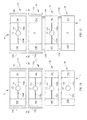
- FIGS. 42A through 42H are schematic plan views showing a noncomprehensive set of options for arranging master and slave wings on one or more deck segments.
- deck sections are designated by D, D1 or D2
- master wings by M slave wings by S
- joints by J nonarticulating (non-joint) connecters by C and gear racks by R.
- FIG. 42H is a schematic of the specific architecture of FIGS. 35-41 .
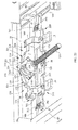
- the retrofit kit for upgrading a bed includes a rack 1090 affixable to a deck expansion wing, a drive shaft 1092, mounting hardware such as pedastal brackets 1094 for rotatably mounting the drive shaft to a bed frame, and components of a drive system which is engageable with the drive shaft and securable to the bed frame.
- the drive shaft itself may include pinions 1106 engageable with a rack when the rack is affixed to the wing and the drive shaft is mounted on the bed frame.
- the kit may include pinions 1106 which are mountable on the drive shaft such that the pinion is engageable with the rack when the rack is affixed to the wing and the drive shaft is mounted on the bed frame.
- the drive shaft 1092 may be an assembly comprising at least two sections connected together by a flexible joint 1100 such as universal joints so that when the shaft is mounted on the bed frame each flexible joint will be located to accommodate changes in angular orientation of adjacent deck segments of the bed (e.g. at locations 1102 of FIG. 36 ).
- the kit may include at least two individual shaft sections such as sections 1092a through 1092d and flexible joints 1100 (one for each pair of shaft sections to be flexibly connected to each other) for connecting one of the sections to the other of the sections.
- Each shaft section has a length such that each flexible joint will be located to accommodate changes in angular orientation of adjacent deck segments of the bed when the hardware is retrofit onto the host bed frame.
- the retrofit kit also includes a drive element 1112 rotatably secureable to the bed frame, a driven element 1114 securable to the drive shaft so that the driven element and the drive shaft are co-rotatable, means for rotating the driven element in response to rotation of the drive element, and means for rotating the drive element.
- the drive element and driven element are pulleys 1112P, 1114P and the means for rotating the driven pulley in response to rotation of the drive pulley is a belt 1116 engageable with the pulleys.
- the means for rotating the drive element of the kit may be a manually operable crank 1120. or a motor 1122 ( FIG. 41 ).
Landscapes
- Health & Medical Sciences (AREA)
- Nursing (AREA)
- Life Sciences & Earth Sciences (AREA)
- Animal Behavior & Ethology (AREA)
- General Health & Medical Sciences (AREA)
- Public Health (AREA)
- Veterinary Medicine (AREA)
- Invalid Beds And Related Equipment (AREA)
Abstract
Description
- The subject matter described herein relates to beds of the type used in hospitals, other health care facilities and home health care settings, in particular a bed having at least one powered width expansion wing.
- Beds used in hospitals, other health care facilities and home health care settings include a deck and a mattress supported by the deck. Some beds have a fixed width deck. Other beds include a fixed width center deck section, a left width adjustment wing and a right width adjustment wing. The wings can be stored under the fixed width center section, in which case the deck width equals the width of the fixed width section. The wings can also be stored partially under the fixed width center section so that they each project laterally beyond the lateral edges of the center section by a distance D1, in which case the deck width equals the width of the fixed width section plus two times the distance D1. The wings can also be deployed so that they each project laterally beyond the lateral edges of the fixed width section by a distance D2, which is greater than D1, in which case the deck width equals the width of the fixed width section plus two times the distance D2. With the wings deployed, the bed may be outfitted with a bariatric mattress, which is wider than a nonbariatric mattress, to accommodate a bariatric occupant. A typical bariatric mattress has a center section, a left width augmentation section and a right width augmentation section. Examples of augmentation sections include air filled bladders and foam inserts. The width adjustment wings are useful because with the wings deployed in order to accommodate a bariatric occupant the bed is too wide to fit through a typical doorway. When it becomes necessary to transport the occupant to a different location without removing him or her from the bed, the wings can be temporarily moved to their stored position and the mattress can be temporarily reduced in width, for example by deflating the augmentation bladders or laterally compressing the augmentation foam, so that the bed is able to fit through the doorways. Upon reaching the intended destination the bed can then be restored to its bariatric configuration, i.e. with the wings deployed and the mattress re-expanded to its bariatric width.
- In a typical width adjustable bed the stored position of the wings is underneath the fixed width deck section. A caregiver deploys the wings by manually pulling them laterally away from the longitudinal centerline of the bed, and stores them by manually pushing them laterally toward the centerline.
US Patent 7,730,562 describes a bed having powered width expansion wings. The only specific means disclosed for powering the wings are a hydraulic cylinder or a linear actuator. Such actuation devices can suffer from disadvantages such as bulk, weight and cost. Accordingly, it is desirable to devise more compact, lightweight, low cost systems for powering the expansion wings without sacrificing simplicity and reliability. It is also desirable if such systems can be retrofit onto existing beds having manually operated wings. It is also desirable if such systems or their components can be economically and easily repaired or replaced when necessary. - A bed disclosed herein comprises a fixed width section having a width and an outboard edge, a wing movably coupled to the fixed width section, a motor assembly mechanically grounded to one of the fixed width section and the wing, and a lead screw coupled to the motor assembly and to a lead screw receiver nonmovably associated with the other of the fixed width section and the wing. In practice, operation of the motor is capable of moving the wing between a deployed position in which a lateral extremity thereof is outboard of the outboard edge and a stored position in which the lateral extremity is inboard of its deployed position.
- A retrofit kit as disclosed herein for upgrading a host bed having manually operable width extension wings comprises a motor assembly, a bracket for mounting the motor assembly to a bed frame, a lead screw set comprising oppositely handed lead screws each attachable to the motor assembly, and a lead screw support bracket set. Each member of the support bracket set is securable to a width extension wing of the host bed. The members of the support bracket set have oppositely handed lead screw receivers.
- The invention will now be further described by way of example with reference to the accompanying drawings, in which:
-
FIG. 1 is a simplified schematic right side elevation view of a hospital bed. -
FIG. 2 is a perspective view of a hospital bed deck having a fixed width center deck section, a left width adjustment wing and a right width adjustment wing as seen by an observer looking from beneath the deck. -
FIG. 3 is a view of a typical deck segment, specifically a thigh deck segment, as seen by an observer looking from beneath the segment. -
FIG. 4 is a perspective view showing the right outboard portion of a typical deck segment, specifically an upper body deck segment, as seen by an observer looking from beneath the segment. -
FIGS. 5A and 5B are perspective views showing the right outboard portion of a typical deck segment, specifically a torso deck segment, with a width adjustment wing in its deployed state (FIG. 5A ) and its stored state (FIG. 5B ) as seen by an observer looking from above the segment. A deck plate which rests atop the deck framework is absent from the illustration in order to expose to view components that would otherwise be obscured. -
FIG. 6 is a view of a portion of a deck segment as seen by an observer looking from beneath the segment showing part of a width expansion wing in relation to a crossbar of a bed frame. -
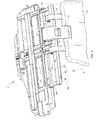
FIG. 7 is a partially exploded perspective view of a motor assembly, a motor mounting bracket, a coupling shaft, a pair of a lead screws, and a coupling collar shown in the contxt of a bed frame crossbar and an inboard connector component of a typical width expansion wing. -
FIGS. 8-9 are schematic plan views comparing kinematic inversions of beds with width expansion wings. -
FIG. 10 is a perspective view of a portion of a seat deck segment as seen from beneath the segment showing an alternative mounting bracket for the motor assembly and also showing the width expansion wings in their stored positions. -
FIG. 11 is a schematic plan view of a bed with width expansion wings coupled to each of four deck segments and with a dedicated motor associated with each segment. -
FIG. 12 is a view similar to that ofFIG. 11 showing an architecture in which a common motor services the width expansion wings of more than one deck segment. -
FIG. 13 is a side view showing a link connecting the width expansion wings of neighboring deck segments. -
FIG. 14 is a perspective view of components of a retrofit kit for upgrading a bed having manually operated width expansion wings, the kit including a motor assembly mounting bracket for attaching a motor assembly to a suitably located bed frame component. -
FIG. 15 is a perspective view of components of an alternative retrofit kit for upgrading a bed having manually operated width expansion wings, the kit including an alternative motor assembly mounting bracket for attaching a motor assembly to a bed frame that does not already include a frame component suitable for mounting the motor assembly. -
FIGS. 16-18 are perspective views of a portion of a deck segment, as seen from beneath the segment, showing the alternative bracket ofFIG. 15 used to mount a motor assembly. -
FIGS. 19 ,20 ,20A and21 are perspective views of a manual release according to one illustrative embodiment of the current disclosure including a carrier. -
FIG. 22 is a perspective view of a manual release similar to that ofFIGs. 19-21 according to another illustrative embodiment. -
FIGS. 23-24 are perspective views of a manual release according to another illustrative embodiment of the current disclosure. -
FIGS. 25-27 are perspective views of the manual release ofFIGs. 23-24 according to another illustrative embodiment. -
FIG. 27A is a plan view in thedirection 27A--27A ofFIG. 27 . -
FIGs. 28-32 are perspective views of a manual release according to another illustrative embodiment of the current disclosure. -
FIG. 33 is perspective views of a manual release according to another illustrative embodiment of the current disclosure. -
FIG. 34 is a schematic side elevation view of selected components a hospital bed. -
FIG. 35 is a more realistic right side elevation view of a hospital bed frame, a deck section including width expansion wings, and a rack and pinion mechanism for extending and retracting the wings. -
FIG. 36 . is a plan view in direction 3--3 ofFIG. 35 . -
FIG. 37 . is a perspective view of the frame, deck section, width expanion wings, and rack and pinion mechanism ofFIG. 36 as seen by an observer looking from underneath the frame. -
FIGS. 38 and 39 are perspective views of a portion of a representative deck segment showing a deck expansion wing in an extended or deployed position (FIG. 38 ) and a retracted or stored position (FIG. 39 ) and also including reference lines to indicate the location of the outboard edge of a fixed width portion of the segment and the location of the outboard edge of the wing. -
FIG. 40 is a perspective view of a representative deck segment and a pair of expansion wings as seen from underneath the segment. -
FIG. 41 is a plan view similar toFIG. 36 showing a motor used to effect extension and retraction of the expansion wings. -
FIGS. 42A - 42H are schematic plan views showing a noncomprehensive set of options for arranging master and slave wings on one or more deck segments. -
FIG. 43 is an exploded perspective view showing components of a retrofit kit arranged substantially as they would be arranged on a bed as seen from above. - Referring to
FIGS. 1 and2 ahospital bed 20 includes abase frame 22 and anelevatable frame 24. A lift system represented bylinks 26 renders the elevatable frame vertically moveable relative to the base frame. The bed extends longitudinally from a head end H to a foot end F and laterally from a right side R (seen in the plane of the illustration) to a leftside L. Casters 28 extend from the base frame tofloor 40. Theelevatable frame 24 includes adeck 30 comprising longitudinally distributed deck segments. The deck segments include an upper body ortorso deck segment 32 corresponding approximately to an occupant's torso, aseat deck segment 34 corresponding approximately to an occupant's buttocks, athigh deck segment 36 corresponding approximately to an occupant's thighs, and acalf deck segment 38 corresponding approximately to an occupant's calves. The upper body, calf, and thigh deck segments are orientation adjustable through angles α, β and θ. The bed also includes acontroller 42 for controlling various functions of the bed and auser interface 44 in communication with the controller. -
Deck segments wings 50 movably coupled to a fixedwidth center section 52. The fixed width center section has a width WF measured between left and right outboard edges 54, 56. In the illustration all four segments are width adjustable segments with both left and right wings. Alternatively, one or more wings could be coupled to only one side (left or right) of the bed. The illustrated bed has ten wings, two of which (one left and one right) are coupled to each of the seat, thigh and calf segments and four of which (two left and two right) are coupled to the upper body segment. Amattress 60 rests on the deck. - As seen in
FIG. 3 , a typical deck segment includes a pair of longitudinally spaced apartcrossbars 64, connected together by longitudinally extending rails 68. The illustrated crossbars are in the form of C-channels having open sides 66 (seen best inFIG. 4 ) that face toward each other. - The bed also includes left and right head end siderails 70, and left and right
foot end siderails 72. As seen most clearly inFIG. 4 , each siderail is connected to awing 50 by acenter link 74 and a longitudinally split link 76 such that thesiderail wing 50 andlinks - Each wing comprises a pair of longitudinally spaced apart spars 80, an inboard connector 82 (also referred to as a lead screw support bracket) spanning longitudinally between the spars at their inboard ends, an
outboard beam 84 spanning longitudinally between the spars at their outboard ends, and apanel 88 extending between the spars and overlying the outboard beam. As seen best inFIG. 4 ,outboard edge 90 ofpanel 88 andoutboard face 92 ofbeam 84 lie in approximately a commonvertical plane 94 and therefore define the outboard lateral extremity of the wing.Connector 82 includes alead screw receiver 96 comprising a threaded bore 98 (seen best inFIGS. 14-15 ) that penetrates through the connector. The receivers on the left and right wings are oppositely handed and each receiver is nonmovable relative to its respective wing. Each wing spar 80 nests in one of the deck segment C-channels 64 so that the spars, and therefore the wing, are laterally translatable relative to fixedwidth section 52. As seen best inFIG. 6 , the illustrated embodiment includesbearings 102 rotatably attached to the spars to reduce resistance when the wings translate relative to the fixed section. Other types of interfaces between the spars and the C-channels, such as rollers, could also be used. - Referring additionally to
FIG. 7 , the bed also includes a leadscrew driver such asmotor assembly 110 comprising anelectric motor 112 and agear train 114, such as a worm and pinion, housed in ahousing 116. The motor assembly is mechanically grounded to fixedwidth section 52. Specifically the motor assembly is bolted to amotor mounting bracket 120 which itself is bolted to rail 68. Acoupling shaft 124, which is rotatably driven by the gear train, projects out of the left and right sides ofhousing 116. One end of alead screw 126L having arotational axis 128L is coupled to one end ofshaft 124, and therefore tomotor assembly 110, by acoupling collar 130 and a pair of R-pins 134. The other end oflead screw 126L is received inreceiver 96 ofleft wing 50L. Anotherlead screw 126R is coupled to the other end ofshaft 124, and therefore tomotor assembly 110, by anothercoupling collar 130 and an additional pair of R-pins 134. The other end oflead screw 126R is received inreceiver 96 ofright wing 50R so that itsrotational axis 128R is colinear withaxis 128L. The colinear axes 128L, 128R define a common rotational axis for the lead screws. Lead screws 128L, 128R are oppositely handed as are the lead screw receivers in the left and right wings. Each lead screw and its receiver are same-handed. -
FIG. 8 schematically show the above described kinematic arrangement in which themotor assembly 110 is mechanically grounded to fixedwidth section 52 and the lead screw receivers are nonmovably associated with each wing.FIG. 9 shows a kinematic inversion in which amotor assembly 110 is mechanically grounded to eachwing 50 and the lead screw receivers are nonmovably associated with fixedwidth sections 52. In the architecture ofFIG. 9 coordination of the direction of movement of the width expansion wings can be accomplished with oppositely handed lead screws or with opposite motor rotational directions. - In practice, operation of the motor in a first rotational direction moves the left and right wings in unison in a laterally outboard direction. Operation of the motor in a second rotational direction, opposite that of the first rotational direction, moves the wings in unison in a laterally inboard direction. In particular the motor can move the wings between a deployed position in which the
lateral extremity 92 of the wing is outboard of theoutboard edge 56 or 58 of the fixed width section 52 (e.g.FIGS. 2-5A ) and a stored position in which thelateral extremity 92 is inboard of its deployed position (FIGS. 5B ,10 ). When the wing is stored itsoutboard extremity 94 may be outboard of, inboard of, or substantially laterally aligned withoutboard edge 56 or 58 of fixedwidth section 52. -
FIG. 11 is a schematic representation of the above described architecture having four deck segments, all four of which are width adjustable. The motor (or a set of motors in the variant in which the motors are mechanically grounded to the wings) is associated with and dedicated to one and only one of the foursegments -
FIGS. 12-13 show an alternative in which the wings of at least two of the width adjustable segments are movable by a common motor assembly. Specifically, amotor assembly 110 is mechanically grounded tocenter section 52 ofthigh deck segment 36.Wings 50 ofsegment 36 are master wings driven directly by the common motor assembly.Wings 50, of the seat andcalf segments link 138 which conveys the lateral motion of the master wings to the slave wings. The slave wings are considered to be indirectly driven because the master wings intervene between the motor assembly and the slave wings. The wings of the upper body section ofFIG. 9 are serviced by a motor dedicated to the upper body section. - The foregoing explanation and accompanying illustrations are directed to beds manufactured with the powered width adjustment feature. However a retrofit kit may be provided for upgrading beds having manually operable width expansion wings. As seen in
FIGS. 14-15 a retrofit kit includes at least amotor assembly 110, a motor mount bracket 120 (FIG. 14 ) or 140 (FIG. 15 ) for mounting the motor assembly to a bed frame, a lead screw set comprising oppositely handed lead screws 126L, 126R each of which is attachable to the motor assembly, and a lead screw support bracket set comprising a pair of leadscrew support brackets 82. The members of the lead screw support bracket set have oppositely handedlead screw receivers 96 and are securable to a width extension wing e.g. by welds or bolts. Other hardware such as acoupler shaft 124,coupling collars 130, R-clips 134 and other fasteners may also be part of the kit. AlthoughFIGS. 14-15 show several kit components as individual parts, certain kit components, such as the motor assembly and motor mount bracket, can be preassembled to each other rather than provided as individual components. -
FIGS. 14 and 15 show two different styles of motor mount brackets.Motor mount bracket 120 ofFIG. 14 is configured to attach the motor assembly to a preexisting, longitudinally extendingrail 68 of the bed frame, forexample rail 68 ofFIG. 3 .Motor mount bracket 140 ofFIG. 15 is configured to span longitudinally betweencrossbars 64 of the bed frame. The ends ofbrackets 140 are secured to the crossbars by bolts (not shown).Bracket 140 is useful if the deck segment or segments of interest do not have a suitable, preexistingrail 68 to which the bracket can be attached.FIGS. 16-18 are views ofbracket 140 shown in the context of a bed frame but with the mounting bolts not illustrated. -
FIGS. 19-21 show amanual release 300 according to one illustrative embodiment of the current disclosure, which takes the place ofconnector 82 of previously described embodiments.Manual release 300 comprises a release unit which includes asplit clasp 314. In some embodiments, including that ofFIGS. 19-21 , the release unit also includes a carrier such ascarrier 316A (FIG. 20A ) in addition to the split clasp. The release unit plays a role similar to that ofleadscrew receiver 96 of previously described embodiments. Themanual release 300 allows a user to disengage the split clasp from thelead screw 126, or from the carrier in embodiments that include a carrier, so that the user can manually position the wing. 50. - The
manual release 300 includes ahandle 302, acable 304, asupport bracket 306, afirst pivot arm 308, asecond pivot arm 310, springs 312, and aclasp 314. When the user wishes to manually position thewing 50, the user actuates thehandle 302 to pull on thecable 304 and cause the first pivot arm and the second pivot arm to rotate, which moves theclasp 314 from a first position where theclasp 314 engages acarrier 316 coupled to thelead screw 126 to a second position where theclasp 314 is disengaged from thecarrier 316. - The
clasp 314 is coupled to thesupport bracket 306 and includes afirst clasp portion 326 and asecond clasp portion 328. Thesupport bracket 306 is coupled between the wing spars 80 and includes guide slots 330 (FIG. 21 ) that are configured to be engaged by thefirst clasp portion 326 and thesecond clasp portion 328. - The
carrier 316A is generally cylindrically shaped and includes tapered ends 318 and a recessedcenter portion 320 positioned between the tapered ends 318. In one possible embodiment (e.g.FIGS. 19-21 ) first ends 334 include acurved portion 338 that defines an opening in the form of acircular bore 340 when the first ends 334 offirst clasp portion 326 and thesecond clasp portion 328 face one another. In the embodiment ofFIGS. 19-21 the perimeter of the circular opening is interrupted bynotches 323 andspaces 325 between the clasp portions as seen best inFIG. 20 . Thecarrier 316A is compatible with the notched/circular opening. As seen inFIG. 20A thecarrier 316A has four equiangularly distributedkeys 322A. Thekeys 322A and the correspondingnotches 323 andspaces 325 in the clasp halves cooperate to prevent the carrier from rotating relative to the clasp when the clasp engages the carrier. In some contemplated embodiments, thecarrier 316A includes a secondtapered portion 324 extending between the tapered ends 318 and the recessedportion 320. Thecarrier 316 includes internal threads that engage the external threads on thelead screw 126 and allow thecarrier 316 to move along thelead screw 126. Provided theclasp 314 is engaged with the carrier, the motion of the carrier along the leadscrew (e.g. when the leadscrew is rotated by an electric motor) will move the clasp laterally and will therefore move the wing between its extended (deployed) and retracted (stored) positions. If a user wishes or needs to move the wing manually he may disengage the clasp from the carrier by way ofhandle 302, as described below in more detail, and push or pull the wing to the desired position. As a result the clasp will no longer be laterally aligned with the carrier. When the user releases handle 302 the clasp halves 326, 328 return to their first position, i.e. the postion in which they would engage the carrier if the carrier were between the clasp halves. To reengage the clasp and carrier with each other the user can push or pull the wing, and therefore the carrier, toward the clasp. As the user continues to move the wing and carrier the carrier tapered ends 318 cause theclasp 314 to open and allow thetapered end 318 to pass through so that theclasp 314 can re-engage the recessedportion 320 andkeys 322A of the carrier. Thekeys 322A are configured to engage theclasp 314 to prevent rotation of thecarrier 316A with respect to theclasp 314. If thecarrier 316A were allowed to rotate, thecarrier 316A would not travel along thelead screw 126 and thewing 50 would not be extended. - The
first clasp portion 326 and thesecond clasp portion 328 are configured to cooperate to removably retain thecarrier 316A. Thefirst clasp portion 326 and thesecond clasp portion 328 include a guide follower 332 (FIG. 33 ), afirst end 334 configured to engage thecarrier 316, and asecond end 336 configured to be pivotably coupled to the first pivot arm 308 (or the second pivot arm 310). Theguide followers 332 are configured to be positioned in theguide slots 330 and to move along theguide slots 330 between a second position where thefirst clasp portion 326 and thesecond clasp portion 328 are separated a distance to disengage thecarrier 314 and a first position where thefirst clasp portion 326 and thesecond clasp portion 328 cooperate to removably retain thecarrier 314. - In another embodiment (
FIG. 22 ) bore 340 is noncircular.Carrier 316 includes a firsttapered portion 318, a secondtapered portion 324 and a central recessedportion 320. Thecarrier 316 includes internal threads that engage the external threads on thelead screw 126 and allow thecarrier 316 to move along thelead screw 126.Carrier 316 includes twokeys 322, a first key which is visible in the illustration and a second key which is the same as the first key but extends along the recessed center portion at a location 180 degrees offset from the first key and therefore is not visible in the illustration. Each key has a pair offlanks 319, only one of which is visible inFIG. 22 . The upper portions of the flanks are angled toward each other to form apeak 321. In the embodiment ofFIG. 22 the clasp portions include a key engaging portion orcorner 342 and akey guide surface 344 on the underside of clasp first ends 334. If the clasps are moved toward the carrier and thekeys 322 are oriented vertically, surfaces 327 of the clasp portions will engage the keys so that the carrier cannot rotate relative to the clasp. If the keys are oriented slightly off-vertical, surfaces 327 will contact the keys and rotate the carrier so that the keys are vertical. If the key is not oriented substantially vertically, guide surfaces 344 will cause thekeys 322, and therefore the carrier as a whole, to rotate toward the key engaging portions orcorners 342. The corners, once they engage the keys, prevent further rotation. - The
handle 302 is coupled to thebeam 84 and includes alever 346 pivotably coupled to ahandle base 348 and configured to move with respect to ahandle base 348 when pulled or pushed by a user. Thelever 346 is connected to thecable 304 and is configured to pull on thefirst pivot arm 308 when thelever 346 is actuated. In one contemplated embodiment, as shown inFIGs. 26 and27 , thecable 304 is coupled to alock linkage 350 that includes afirst link 352 coupled to thefirst pivot arm 308 and asecond link 354 pivotably coupled to thesupport bracket 306. The second link is configured to selectively engage theclasp 314 for example by abutting contact between the clasp and theend surface 313 of the link. Thelock linkage 350 guards against unwanted disengagement of thecarrier 316 from theclasp 314, for example when an off-center push or pull force is applied to thewing 50 that would cause theclasp 314 to open slightly and release thecarrier 316 if the lock linkage were not present. When thehandle 302 is actuated, thecable 304 pulls on thefirst link 352, which causes thefirst pivot arm 308 to rotate and thesecond link 354 to rotate. In some contemplated embodiments, thefirst link 352 includes aslot 353 that thefirst pivot arm 308 is coupled to, and thesecond link 354 includes aslot 355 that thefirst link 352 is coupled to. The slots allowlinks link surface 313 from the clasp without causingpivot arms cable 304 cause the clasp portions to move away from the leadscrew. - The
first pivot arm 308 is generally T-shaped and is connected to thesupport bracket 306 at a first joint J1. Thefirst pivot arm 308 includes afirst member 356, asecond member 358, and athird member 360. Thefirst member 356 is connected to thecable 304 at a second joint J2 and to aspring 312 at a third joint J3. Thesecond member 358 is pivotably connected to thesecond pivot arm 310 at a fourth joint J4. Thethird member 360 is pivotably connected to thesecond clasp portion 328 at a fifth joint J5. As thecable 304 pulls on thefirst member 356, thefirst pivot arm 308 rotates about the first joint J1 causing thespring 312 to stretch and thesecond pivot arm 310 andsecond clasp portion 328 to move with respect to thesupport bracket 306. - The
second pivot arm 310 is generally T-shaped and is connected to thesupport bracket 306 at a sixth joint J6. Thesecond pivot arm 310 includes afourth member 362, afifth member 364, and asixth member 366. Thefourth member 362 is pivotably connected to thesecond member 358 of thefirst pivot arm 308 at the fourth joint J4. Thefifth member 364 is connected to aspring 312 at a seventh joint J7. Thesixth member 366 is pivotably connected to thefirst clasp portion 326 at an eighth joint J8. Rotation of thefirst pivot arm 308 about the first joint J1 causes thesecond pivot arm 310 to rotate about the sixth joint J6 by way of thesecond member 358 and thefourth member 362, which causes thespring 312 connected to thesupport bracket 306 and thesecond pivot arm 310 to stretch and thefirst clasp portion 326 to move with respect to thesupport bracket 306. - The
springs 312 are connected between thesupport bracket 306 and the first andsecond pivot arms springs 312 are configured to bias the first andsecond pivot arms second clasp portions carrier 316. -
FIGS. 23-27 show a manual release 400 according to another illustrative embodiment of the current disclosure. In this contemplated embodiment, the manual release 400 includes aclasp 402 configured to engage the threads of thelead screw 126 directly rather than by way of a carrier. In order for thewing 50 to be manually moved, the user must maintain actuation of thehandle 302 to prevent theclasp 402 from re-engaging the threads on thelead screw 126. When thehandle 302 is released, thesprings 312 pull on thefirst pivot arm 308 and thesecond pivot arm 310 and cause them to rotate from the second position to the first position, which then causes theclasp 402 to move from the disengaged position to the engaged position where theclasp 402 engages the threads on thelead screw 126. -
Clasp 402 includes afirst portion 404 and asecond portion 406, which operate similarly to the first clasp portion and the second clasp portion previously disclosed herein. Thefirst portion 404 and thesecond portion 406 each include afirst end 408 and asecond end 410. Thesecond pivot arm 310 is coupled to thesecond end 410 of thefirst portion 404, and thefirst end 408 includes a threadedportion 412 configured to engage the threads on thelead screw 126. When thefirst end 408 of thefirst portion 404 and thefirst end 408 of thesecond portion 406 face one another, they cooperate to form a threadedbore 413 that engages the threads on thelead screw 126. In one contemplated embodiment (FIGS. 25-27 ), instead of the guide slots being in thesupport bracket 306, theguide slots 414 can be located in thefirst portion 404 and thesecond portion 406 and can be engaged byguide pins 416 coupled to thesupport bracket 306. In one contemplated embodiment (also seen inFIGS. 25-27 ), thefirst portion 404 and thesecond portion 406 are keyed to help prevent angular misalignment when the portions engage one another. The keying feature includesoblique surfaces FIG. 27A (with onesurface 417 also being evident inFIG. 27 ) on first andsecond portions FIG. 27 , then as the first and second portions approach each other to re-engage the leadscrew, the oblique surfaces 417, 419 correct any angular misalignment between the first and second portions as those portions come together. -
FIGs. 28-33 show amanual release 500 according to another illustrative embodiment of the current disclosure. In this contemplated embodiment, themanual release 500 includes aclasp 502 configured to engage acarrier 504. Thecarrier 504 includes tapered ends 506, a recessedportion 508 positioned between the tapered ends 506, and a key 510 extending along the top surface of thecarrier 504 as shown inFIGs. 30 and32 In some contemplated embodiments, thecarrier 504 includes a second tapered portion 512 (FIG. 29 ) extending between the tapered ends 506 and the recessedportion 508. Thecarrier 504 includes internal threads (not shown) that engage the threads on thelead screw 126 and allow thecarrier 504 to move along thelead screw 126. The tapered ends 506 are configured to assist thecarrier 504 in re-engaging theclasp 502 so that the user can again use the powered width extension. The tapered ends 506 work substantially the same way as the tapered ends 318 of the carriers ofFIGS. 19-22 . In one contemplated embodiment, the tapered ends 506 engage theclasp 502 and cause theclasp 502 to open and allow thetapered end 506 to pass through so that thecarrier 504 can engage the recessedportion 508. The key 510 protrudes from the upper surface of thecarrier 504 and is configured to engage aguide track 514 that extends along the length of thelead screw 126. Theguide track 514 includes agroove 516 therein that the key 510 rides in. Theguide track 514 prevents the key 510 from rotating with thelead screw 126, which causes thecarrier 504 to move along thelead screw 126 as it rotates. Maintaining the orientation of thecarrier 504 with respect to theelevatable frame 24 allows a user (or a predefined function of the control system 600) to activate the motor to drive thecarrier 504 to re-engage the clasp 502 (whether it is retracted or extended). Limit switches 602 (FIG. 29 ) are coupled to theguide track 514 and are configured to be activated when thecarrier 504 reaches the fully extended and the fully retracted positions. -
Clasp 502 includes afirst portion 518 and asecond portion 520, which operate similarly to the first clasp portion and the second clasp portion previously described herein. Thefirst portion 518 and thesecond portion 520 include afirst end 522 and asecond end 524. Thesecond pivot arm 310 is coupled to thesecond end 524 of thefirst portion 518. Thefirst end 522 includes aguide slot 526 configured to be engaged by aguide pin 528 coupled to thesupport bracket 306. The first end also includes recessedportion 530 configured to engage the recessedportion 508 of thecarrier 504. - In another contemplated embodiment, the
hospital bed 20 includes acontrol system 600 that is configured to receive signals from sensing elements coupled to the manual release. In one contemplated embodiment, the sensing element is alimit switch 602 as shown inFIG. 29 . Thelimit switch 602 is configured to sense when thewing 50 is in its fully retracted or fully extended positions. In another contemplated embodiment, the sensing element includes a potentiometer, a hall-effect sensor, or other sensing devices. In some contemplated embodiments, when thecontrol system 600 receives a signal from the sensing element that thewing 50 is in its fully extended or fully retracted position, thecontrol system 600 can activate alock 604 configured to maintain thewing 50 in its current position. In one contemplated embodiment, the user presses the width expansion/retraction button on auser interface 606 to release thelock 604. In other contemplated embodiments, thelock 604 can be released by pulling on themanual release handle 302. In some contemplated embodiments, thelock 604 includes a locking gas spring or an electric locking mechanism. In some contemplated embodiments, the user is alerted (with audio and/or visual indicators, such as, lights and/or images on a display) when thewing 50 is not fully extended or retracted. In other contemplated embodiments, the user can be alerted that thewings 50 on the bed are not synchronized, i.e., one is not fully extended, but the others are. - In one contemplated embodiment, the
control system 600 is configured to alert a user visually or audibly when the carrier is engaged by the clasp. In some contemplated embodiments, a hall-effect sensor 608 is coupled to thesupport bracket 306 and amagnet 612 is recessed into the carrier as shown inFIG. 33 . In one contemplated embodiment, one or more hall-effect sensors FIG. 33 ) can be used to sense when the carrier has passed over the hall-effect sensor 602. If two sensors are used, they can be positioned on thesupport bracket 306 or on the clasp so that when the carrier is retained by the clasp, the Hall effect sensor is positioned proximate to the magnet in the carrier. In another contemplated embodiment, the hall-effect sensors 608 can be coupled to aseparate bracket 610, which may be welded or otherwise secured tobracket 306, and spaced apart from each other a predetermined distance as shown inFIG. 33 . When thecontrol system 600 receives two signals from afirst sensor 608a and no signals from thesecond sensor 608b, thecontrol system 600 determines that the twomagnets 612 in the carrier have passed over the first sensor and the carrier should be engaged by the clasp since the second sensor did not indicate that the carrier had passed over it. In another contemplated embodiment, a pressure sensor (not shown) is coupled to the first end of the clasp portions to determine when the carrier is engaged by the clasp. - Referring to
FIG. 34 ahospital bed 1020 includes abase frame 1022 and anelevatable frame 1024. A lift system represented bylinks 1026 renders the elevatable frame vertically moveable relative to the base frame. The bed extends longitudinally from a head end H to a foot end F and laterally from a right side R (seen in the plane of the illustration) to a left side L seen in the more realistic depictions ofFIGS. 35-37 .Casters 1028 extend from the base frame tofloor 1040. Theelevatable frame 1024 includes adeck 1030 comprising longitudinally distributed deck segments. The deck segments include an upper body ortorso deck segment 1032 corresponding approximately to an occupant's torso, aseat deck segment 1034 corresponding approximately to an occupant's buttocks, athigh deck segment 1036 corresponding approximately to an occupant's thighs, and acalf deck segment 1038 corresponding approximately to an occupant's calves. The angular orientations α, β and θ of the upper body, calf, and thigh deck segments are adjustable. Each deck segment supports a deck panel, not shown in the illustrations, to support a mattress 1048. The bed also includes acontroller 1042 for controlling various functions of the bed and auser interface 1044 in communication with the controller. - Referring additionally to
FIGS. 35-39 , the bed also includes left and right head end siderails 1070, and left and rightfoot end siderails 1072. Each siderail is connected to a wing 1050 (described in more detail below) by acenter link 1074 and alongitudinally split link 1076 such that thesiderail links -
Deck 1030 comprises a fixedwidth center section 1052 and one or more wings 1050. Each wing is moveably coupled to one ofdeck segments FIGS. 35-38 ) and a retracted or stored position (FIG. 39 ). The fixedwidth center section 1052 has a width WF measured between its left and right laterallyoutboard edges segments Wings seat section 1034.Wings 1050D, 1050I are moveably coupled tothigh section 1036.Wings calf section 1038.Wings upper body section 1032. Referring additionally toFIG. 40 wings gear rack 1090 and are referred to as master wings. The remaining six wings are slave wings. - The bed also includes a pair of
drive shafts 1092 mounted to the bed frame by way of mountingbrackets 1094 such as the pedastal bearings seen in the illustrations so that the shaft is rotatable about shaft axis As. As seen most clearly inFIG. 43 each shaft is made of four shaft segments designated 1092a through 1092d connected together by a flexible joints such asuniversal joints 1100. As shown inFIG. 36 each shaft is mounted in the pedestal bearings so that thelongitudinal location 1102 of each flexible joint 1100 is at or near the neighboring ends of adjacent deck segments thereby accommodating changes in the relative angular orientations α, β, θ of adjacent deck segments. - Each shaft also includes one or
more pinions 1106 corotatable with the drive shaft. Each pinion is engaged with acorresponding rack 1090. The pinions may be formed integrally with the shaft segment or may be distinct from the shaft but corotatably mounted thereon. - The bed also includes a
drive system 1110 for rotating the drive shaft. The drive system comprises a drive element 1112 such as drive pulley orpulleys 1112P secured to the bed frame, a driven element 1114 such as driven pulley orpulleys 1114P connected to driveshaft 1092, and a connecting element such asbelt 1116 engaged with the drive element and each driven element for conveying rotation of the drive element to the driven elements. As seen best inFIG. 37 the belt on one side of the bed may be twisted to reverse the rotational sense of the drivenpulley 1114P relative to thedrive pulley 1112P. Other arrangements such as gear trains and sprocket/chain arrangements may also be used. - The drive system also includes a manually operable crank 1120 connected to the drive element. In an alternative embodiment seen in
FIG. 41 the drive system includes anelectric motor 1122 connected to the drive element. Operation of the drive system (e.g. by manually turning the crank or operating the motor) causes the rotary motion of the crank or motor to be conveyed to the driven elements (e.g. drivenpulleys 1114P). Rotation of the driven elements rotatesdrive shafts 1092 and theirpinions 1106 which, due to their engagement withracks 1090, moves the wing to which the racks are attached between a deployed position (e.g.FIGS. 35-38 ) in which alateral extremity 1058 of the wing is in aposition 1060 outboard of theoutboard edge FIG. 39 ) in which the lateral extremity of the wing is in a position inboard of its deployed position. When the wing is in its stored position the lateral extremity thereof may be outboard ofoutboard edge width section 1052, substantially aligned with the outboard edge, or inboard of the outboard edge. - The specific embodiment of
FIGS. 35-41 includesmaster wings rack 1090, andslave wings pinion 1106 but instead are connected to the master wing such that translation of the master wing by way of its rack and engaged pinion causes translation of the slave wing. In architectures in which a master wing and the slave wing to which it is connected are moveably coupled to different deck segments whose relative angular orientation is nonconstant (e.g.deck sections wings - In another architecture all the wings include
racks 1090 engaged withpinions 1106 that are rotatable by ashaft 1092 in whichcase shaft 1092 is a common drive shaft for rotating all the pinions. -
FIGS. 42A through 42H are schematic plan views showing a noncomprehensive set of options for arranging master and slave wings on one or more deck segments. In these illustrations deck sections are designated by D, D1 or D2, master wings by M, slave wings by S, joints by J, nonarticulating (non-joint) connecters by C and gear racks by R.FIG. 42H is a schematic of the specific architecture ofFIGS. 35-41 . - The foregoing explanation and accompanying illustrations are directed to beds manufactured with the width adjustment wings and associated hardware for extending and retracting the wings. However a retrofit kit may be provided for upgrading beds having width expansion wings that must be manually and individually deployed and stored. As seen in
FIG. 43 . the retrofit kit for upgrading a bed includes arack 1090 affixable to a deck expansion wing, adrive shaft 1092, mounting hardware such aspedastal brackets 1094 for rotatably mounting the drive shaft to a bed frame, and components of a drive system which is engageable with the drive shaft and securable to the bed frame. The drive shaft itself may includepinions 1106 engageable with a rack when the rack is affixed to the wing and the drive shaft is mounted on the bed frame. Alternatively the kit may includepinions 1106 which are mountable on the drive shaft such that the pinion is engageable with the rack when the rack is affixed to the wing and the drive shaft is mounted on the bed frame. - The
drive shaft 1092 may be an assembly comprising at least two sections connected together by a flexible joint 1100 such as universal joints so that when the shaft is mounted on the bed frame each flexible joint will be located to accommodate changes in angular orientation of adjacent deck segments of the bed (e.g. atlocations 1102 ofFIG. 36 ). Alternatively the kit may include at least two individual shaft sections such assections 1092a through 1092d and flexible joints 1100 (one for each pair of shaft sections to be flexibly connected to each other) for connecting one of the sections to the other of the sections. Each shaft section has a length such that each flexible joint will be located to accommodate changes in angular orientation of adjacent deck segments of the bed when the hardware is retrofit onto the host bed frame. - The retrofit kit also includes a drive element 1112 rotatably secureable to the bed frame, a driven element 1114 securable to the drive shaft so that the driven element and the drive shaft are co-rotatable, means for rotating the driven element in response to rotation of the drive element, and means for rotating the drive element. In one embodiment the drive element and driven element are
pulleys belt 1116 engageable with the pulleys. - The means for rotating the drive element of the kit may be a manually
operable crank 1120. or a motor 1122 (FIG. 41 ). - Although this disclosure refers to specific embodiments, it will be understood by those skilled in the art that various changes in form and detail may be made.
- Embodiments of the invention can be described with reference to the following numbered clauses, with preferred features laid out in the dependent clauses:
- 1. A bed comprising:
- a fixed width deck section;
- a wing movably coupled to the fixed width section;
- a leadscrew having a rotational axis;
- a leadscrew driver coupled to the leadscrew for rotating the leadscrew about its axis;
- a release unit coupled to the wing and configured to move between:
- a) an engaged position in which the release unit engages the lead screw and moves therealong as the leadscrew rotates about the rotational axis thereby causing the wing to translate relative to the fixed width section; and
- b) a disengaged position in which the release unit is disengaged from the leadscrew.
- 2. The bed of clause 1 wherein the release unit comprises a clasp having a first portion and a second portion, the first and second portions having threads that engage threads of the leadscrew in the engaged position of the release unit and that are disengaged from the leadscrew threads in the disengaged position of the release unit.
- 3. The bed of clause 1 wherein the release unit comprises a carrier which engages the leadscrew threads and a clasp configured to:
- a) engage the carrier so that the release unit moves along the leadscrew as the leadscrew rotates about the rotational axis thereby causing the wing to translate; and
- b) disengage from the carrier.
- 4. The bed of clause 1 comprising:
- a support bracket along which at least part of the release unit moves in order to traverse between the engaged and disengaged positions; and
- a pivot arm pivotably attached to the support bracket and coupled to the release unit.
- 5. The bed of clause 4 comprising a first pivot arm attached to the support bracket and coupled to a first portion of the release unit and a second pivot arm attached to the support bracket and coupled to a second portion of the release unit.
- 6. The bed of clause 5 wherein the first and second pivot arms are pivotably connected to each other so that pivoting of one of the pivot arms causes pivoting of the other of the pivot arms.
- 7. The bed of clause 4 comprising a lock having a locked state in which the lock resists movement of the release unit and an unlocked state in which the lock does not resist movement of the release unit.
- 8. The bed of clause 7 wherein the lock comprises a lock linkage comprising a first link extending from the pivot arm and a second link extending from the first link and pivotably connected to a mechanical ground such that when the lock is in the locked state the second link resists movement of the release unit and when the lock is in the unlocked state the second link does not resist movement of the release unit.
- 9. The bed of clause 3 wherein the lateral ends of the carrier are tapered so that in the event the carrier is not engaged with the clasp, the tapered ends cause the clasp to open in response to lateral movement of the carrier thereby allowing the clasp and carrier to become re-engaged.
- 10. The bed of clause 3 wherein the carrier includes a key that cooperates with a feature on the clasp to prevent rotation of the carrier relative to the clasp.
- 11. The bed of
clause 10 wherein the feature is a corner and the clasp includes a guide surface to guide the key into the corner. - 12. The bed of
clause 10 wherein the feature is a notch in the clasp and a space between first and second portions of the clasp. - 13. The bed of clause 3 wherein the clasp includes a key to correct misalignment with a cooperating clasp as the clasp and the cooperating clasp approach each other when the clasps transition from the engaged position to the disengaged position.
- 14. The bed of clause 1 comprising:
- a control system configured to determine the engagement status of the release unit and trigger a response as a function of the engagement status.
- 15. The bed of clause 14, wherein the response includes alerting a user as to the engagement status of the release unit.
- 16. The bed of clause 15, wherein the user is alerted by a visual indicator.
- 17. The bed of clause 15, wherein the user is alerted audibly.
- 18. The bed of clause 1 comprising:
- a control system configured to sense the position of the wing and alert a user when the wing is in a deployed position in which a lateral extremity thereof is outboard of the outboard edge and a stored position in which the lateral extremity is inboard of its deployed position.
- 19. The bed of clause 18, wherein the control system includes limit switches configured to sense when the wing is in one of the deployed position and the storage position.
- 20. The bed of clause 1 comprising:
- a locking mechanism; and
- a control system configured to sense the position of the wing and actuate a lock to maintain the wing in a deployed position in which a lateral extremity thereof is outboard of the outboard edge and a stored position in which the lateral extremity is inboard of its deployed position
- 21. The bed of
clause 20, wherein the locking mechanism is released when the release unit is actuated. - 22. The bed of
clause 20, wherein the locking mechanism is released when a width expansion function is activated through a user interface. - 23. A person support apparatus, comprising:
- a fixed width deck section having a width and an outboard edge;
- a wing movably coupled to the fixed width section;
- a motor assembly mechanically grounded to one of the fixed width section and the wing;
- a lead screw having a rotational axis and being coupled to the motor assembly
- a carrier configured to engage the lead screw and move there along as the lead screw rotates about the rotational axis;
- a clasp associated with the other of the fixed width section and the wing, the clasp being configured to move between an engaged position where the clasp removably engages the carrier and a disengaged position where the clasp is disengaged from the carrier; and
- a manual release assembly configured to move the clasp between the engaged position and the disengaged position to allow a user to manually move the wing between a deployed position in which a lateral extremity thereof is outboard of the outboard edge and a stored position in which the lateral extremity is inboard of its deployed position.
- 24. The person support apparatus of clause 23 comprising:
- a control system configured to determine the engagement status of the clasp and the carrier and trigger a response as a function of the engagement status.
- 25. The apparatus of
clause 24, wherein the response includes alerting a user as to the engagement status of the carrier and the clasp. - 26. The apparatus of clause 25, wherein the user is alerted by a visual indicator.
- 27. The apparatus of clause 25, wherein the user is alerted audibly.
- 28. The apparatus of
clause 24, wherein in the event the carrier is not engaging the clasp the response includes the motor rotating the lead screw to move the carrier therealong until the carrier engages the clasp. - 29. The person support apparatus of clause 23 comprising:
- a control system configured to sense the position of the wing and alert a user when the wing is in a deployed position in which a lateral extremity thereof is outboard of the outboard edge and a stored position in which the lateral extremity is inboard of its deployed position
- 30. The apparatus of clause 29, wherein the control system includes limit switches configured to sense when the wing is in one of the deployed position and the storage position.
- 31. The person support apparatus of clause 23 comprising:
- a locking mechanism; and
- a control system configured to sense the position of the wing and actuate a lock to maintain the wing in a deployed position in which a lateral extremity thereof is outboard of the outboard edge and a stored position in which the lateral extremity is inboard of its deployed position
- 32. The apparatus of clause 31, wherein the locking mechanism is released when the manual release assembly is actuated.
- 33. The apparatus of clause 31, wherein the locking mechanism is released when a width expansion function is activated through a user interface.
- Further embodiments of the invention can be described with reference to the following numbered clauses, with preferred features laid out in the dependent clauses:
- 1. A bed comprising:
- a fixed width deck section having a width and an outboard edge;
- a wing movably coupled to the fixed width section, the wing including a rack;
- a drive shaft mounted to the bed frame;
- a pinion rotatable by the drive shaft and engaged with the rack; and
- a drive system for rotating the drive shaft.
- 2. The bed of clause 1 wherein operation of the drive system moves the wing between a deployed position in which a lateral extremity thereof is outboard of the outboard edge and a stored position in which the lateral extremity is inboard of its deployed position.
- 3. The bed of clause 1 wherein the drive system comprises a drive element secured to the bed frame, a driven element connected to the drive shaft, and a connecting element engaged with the drive element and the driven element.
- 4. The bed of clause 3 wherein the drive element and the driven element are pulleys and the connecting element is a belt.
- 5. The bed of clause 3 including a crank connected to the drive element.
- 6. The bed of clause 3 including a motor connected to the drive element.
- 7. The bed of clause 1 wherein when the wing is in its stored position the lateral extremity thereof is outboard of the outboard edge.
- 8. The bed of clause 1 in which when the wing is in its stored position the lateral extremity thereof is substantially aligned with the outboard edge.
- 9. The bed of clause 1 in which when the wing is in its stored position the lateral extremity thereof is inboard of the outboard edge.
- 10. The bed of clause 1 wherein the wing is a master wing and the bed also includes a slave wing moveably coupled to the fixed width deck section and connected to the master wing such that translation of the master wing by way of its rack and engaged pinion causes translation of the slave wing.
- 11. The bed of
clause 10 wherein the master wing and the slave wing are moveably coupled to different deck segments whose relative angular orientation is nonconstant and are connected to each other by a joint that accommodates changes in the relative angular orientation of the deck segments - 12. The bed of clause 1 wherein the fixed width deck section comprises at least a first deck segment and a second deck segment longitudinally spaced from the first deck segment, the first deck segment including a first wing movably coupled thereto, the first wing including a first rack engaged with a first pinion, the second deck segment including a second wing movably coupled thereto, the second wing including a second rack engaged with a second pinion, the drive shaft being a common drive shaft for rotating the first and second pinions.
- 13. A retrofit kit for upgrading a bed having a manually operable width extension wing, comprising:
- a rack affixable to the wing
- a drive shaft;
- mounting hardware for rotatably mounting the drive shaft to a bed frame; and
- a drive system which is engageable with the drive shaft and securable to the bed frame.
- 14. The kit of clause 13 wherein the drive shaft includes a pinion engageable with the rack when the rack is affixed to the wing and the drive shaft is mounted on the bed frame.
- 15. The kit of clause 13 including a pinion mountable on the drive shaft such that the pinion is engageable with the rack when the rack is affixed to the wing and the drive shaft is mounted on the bed frame.
- 16. The kit of clause 13 wherein the drive shaft comprises at least two sections connected together by a flexible joint such that when the shaft is mounted on the bed frame that flexible joint is located so as to accommodate changes in angular orientation of adjacent deck segments of the bed.
- 17. The kit of clause 13 wherein the drive shaft comprises at least two sections and the kit includes flexible joints for connecting one of the sections to the other of the sections.
- 18. The kit of clause 13 wherein the drive system includes a drive element rotatably secureable to the bed frame, a driven element securable to the drive shaft so that the driven element and the drive shaft are co-rotatable, means for rotating the driven element in response to rotation of the drive element, and means for rotating the drive element.
- 19. The kit of clause 18 wherein the drive element and driven element are pulleys and the means for rotating the driven pulley in response to rotation of the drive pulley is a belt engageable with the pulleys.
- 20. The kit of clause 13 wherein the drive system includes a manually operable crank.
- 21. The kit of clause 13 wherein the drive system includes a motor.
Claims (15)
- A bed comprising:a fixed width deck section;a wing movably coupled to the fixed width section;a leadscrew having a rotational axis;a leadscrew driver coupled to the leadscrew for rotating the leadscrew about its axis;a release unit coupled to the wing and configured to move between:a) an engaged position in which the release unit engages the lead screw and moves therealong as the leadscrew rotates about the rotational axis thereby causing the wing to translate relative to the fixed width section; andb) a disengaged position in which the release unit is disengaged from the leadscrew.
- The bed of claim 1 wherein the release unit comprises a clasp having a first portion and a second portion, the first and second portions having threads that engage threads of the leadscrew in the engaged position of the release unit and that are disengaged from the leadscrew threads in the disengaged position of the release unit.
- The bed of claim 1 wherein the release unit comprises a carrier which engages the leadscrew threads and a clasp configured to:a) engage the carrier so that the release unit moves along the leadscrew as the leadscrew rotates about the rotational axis thereby causing the wing to translate; andb) disengage from the carrier.
- The bed of claim 3 wherein the lateral ends of the carrier are tapered so that in the event the carrier is not engaged with the clasp, the tapered ends cause the clasp to open in response to lateral movement of the carrier thereby allowing the clasp and carrier to become re-engaged.
- The bed of either claim 3 or claim 4 wherein the carrier includes a key that cooperates with a feature on the clasp to prevent rotation of the carrier relative to the clasp.
- The bed of any one of claims 3 to 5 wherein the clasp includes a key to correct misalignment with a cooperating clasp as the clasp and the cooperating clasp approach each other when the clasps transition from the engaged position to the disengaged position.
- The bed of any preceding claim comprising:a support bracket along which at least part of the release unit moves in order to traverse between the engaged and disengaged positions; anda pivot arm pivotably attached to the support bracket and coupled to the release unit.
- The bed of claim 7 comprising a lock having a locked state in which the lock resists movement of the release unit and an unlocked state in which the lock does not resist movement of the release unit.
- The bed of any preceding claim comprising:a control system configured to determine the engagement status of the release unit and trigger a response as a function of the engagement status.
- The bed of claim 9, wherein the response includes alerting a user as to the engagement status of the release unit.
- The bed of any preceding claim comprising:a control system configured to sense the position of the wing and alert a user when the wing is in a deployed position in which a lateral extremity thereof is outboard of the outboard edge and a stored position in which the lateral extremity is inboard of its deployed position.
- The bed of claim 11, wherein the control system includes limit switches configured to sense when the wing is in one of the deployed position and the storage position.
- The bed of any preceding claim comprising:a locking mechanism; anda control system configured to sense the position of the wing and actuate a lock to maintain the wing in a deployed position in which a lateral extremity thereof is outboard of the outboard edge and a stored position in which the lateral extremity is inboard of its deployed position
- The bed of claim 13, wherein the locking mechanism is released when the release unit is actuated.
- The bed of claim 13, wherein the locking mechanism is released when a width expansion function is activated through a user interface.
Priority Applications (1)
| Application Number | Priority Date | Filing Date | Title |
|---|---|---|---|
| EP16190437.0A EP3127521B1 (en) | 2013-02-05 | 2014-02-04 | Bed with a powered width expansion wing |
Applications Claiming Priority (4)
| Application Number | Priority Date | Filing Date | Title |
|---|---|---|---|
| US201361760881P | 2013-02-05 | 2013-02-05 | |
| US201361763470P | 2013-02-11 | 2013-02-11 | |
| US201361788210P | 2013-03-15 | 2013-03-15 | |
| US14/168,538 US9173796B2 (en) | 2013-02-05 | 2014-01-30 | Bed with a powered width expansion wing with manual release |
Related Child Applications (1)
| Application Number | Title | Priority Date | Filing Date |
|---|---|---|---|
| EP16190437.0A Division EP3127521B1 (en) | 2013-02-05 | 2014-02-04 | Bed with a powered width expansion wing |
Publications (3)
| Publication Number | Publication Date |
|---|---|
| EP2762122A2 true EP2762122A2 (en) | 2014-08-06 |
| EP2762122A3 EP2762122A3 (en) | 2015-01-21 |
| EP2762122B1 EP2762122B1 (en) | 2016-09-28 |
Family
ID=50030184
Family Applications (2)
| Application Number | Title | Priority Date | Filing Date |
|---|---|---|---|
| EP16190437.0A Active EP3127521B1 (en) | 2013-02-05 | 2014-02-04 | Bed with a powered width expansion wing |
| EP14153781.1A Active EP2762122B1 (en) | 2013-02-05 | 2014-02-04 | Bed with a powered width expansion wing |
Family Applications Before (1)
| Application Number | Title | Priority Date | Filing Date |
|---|---|---|---|
| EP16190437.0A Active EP3127521B1 (en) | 2013-02-05 | 2014-02-04 | Bed with a powered width expansion wing |
Country Status (2)
| Country | Link |
|---|---|
| US (5) | US9173796B2 (en) |
| EP (2) | EP3127521B1 (en) |
Cited By (6)
| Publication number | Priority date | Publication date | Assignee | Title |
|---|---|---|---|---|
| CN104606011A (en) * | 2015-01-27 | 2015-05-13 | 中国科学院苏州生物医学工程技术研究所 | Limiting mechanism |
| EP2954884A1 (en) * | 2014-06-13 | 2015-12-16 | Hill-Rom Services, Inc. | Adjustable person support system with expansion wings driven by dual leadscrews and center mounted motors |
| US9757293B2 (en) | 2013-06-15 | 2017-09-12 | Hill-Rom Services, Inc. | Adjustable person support system with expansion wings driven by dual leadscrews and center mounted motors |
| CN109820654A (en) * | 2019-02-25 | 2019-05-31 | 漯河市第一人民医院 | A kind of surgery wound medical treatment and nursing device and its care method |
| GB2533508B (en) * | 2013-09-06 | 2020-09-16 | Stryker Corp | Patient support usable with bariatric patients |
| EP4066805A1 (en) * | 2021-03-31 | 2022-10-05 | Hill-Rom Services, Inc. | Hospital bed cpr activation assembly |
Families Citing this family (31)
| Publication number | Priority date | Publication date | Assignee | Title |
|---|---|---|---|---|
| EP2768461B1 (en) * | 2011-10-20 | 2015-04-08 | Ferno-Washington, Inc. | Work surface extensions for embalming tables and embalming tables including the same |
| DE102011086037A1 (en) * | 2011-11-09 | 2013-05-16 | Dewertokin Gmbh | Electromotive linear drive, in particular for adjusting reclining and seating furniture |
| US8997282B2 (en) * | 2012-05-10 | 2015-04-07 | Hill-Rom Services, Inc. | Bed with a powered width expansion wing |
| US9622927B1 (en) * | 2012-10-05 | 2017-04-18 | Gf Health Products, Inc. | Bed with extendable and retractable extensions |
| US9173796B2 (en) * | 2013-02-05 | 2015-11-03 | Hill-Rom Services, Inc. | Bed with a powered width expansion wing with manual release |
| US9572735B2 (en) * | 2013-03-15 | 2017-02-21 | Kap Medical, Inc. | Bed systems and method |
| US10188569B2 (en) | 2013-09-06 | 2019-01-29 | Stryker Corporation | Patient support usable with bariatric patients |
| EP3777808B1 (en) | 2014-11-13 | 2023-10-25 | Kap Medical, Inc. | Bed systems |
| CA2925609A1 (en) * | 2015-03-31 | 2016-09-30 | Ted Tekulve | Health care bed with variable width bed frame and method for use thereof |
| US10406044B2 (en) * | 2015-06-25 | 2019-09-10 | Stryker Corporation | Person support apparatuses with drive controls |
| US10660809B2 (en) | 2015-09-11 | 2020-05-26 | Stryker Corporation | Telescoping assembly for use on a patient support apparatus |
| US10849804B2 (en) * | 2015-09-24 | 2020-12-01 | Umano Medical Inc. | Hospital bed with adjustable width |
| US10959894B2 (en) * | 2016-03-03 | 2021-03-30 | Stryker Corporation | Patient support apparatus with actuator feedback |
| US10489661B1 (en) | 2016-03-08 | 2019-11-26 | Ocuvera LLC | Medical environment monitoring system |
| CN105853096B (en) * | 2016-04-28 | 2018-08-03 | 容县康瑞医疗器械有限公司 | The medical bed high suitable for child-resistance |
| JP6517765B2 (en) * | 2016-08-17 | 2019-05-22 | 哲夫 金城 | Stepless lift mechanism of low floor care bed |
| US10600204B1 (en) | 2016-12-28 | 2020-03-24 | Ocuvera | Medical environment bedsore detection and prevention system |
| US11510832B2 (en) * | 2017-11-01 | 2022-11-29 | Umano Medical Inc. | Shock absorbing assembly for a patient support apparatus |
| CN108451685B (en) * | 2018-04-18 | 2020-08-28 | 安徽鑫诺医疗设备有限公司 | Multi-section swing recovery type traction bed |
| CN209018188U (en) * | 2018-04-27 | 2019-06-25 | 革新(厦门)运动器材有限公司 | A kind of beddo |
| CN209018191U (en) | 2018-04-27 | 2019-06-25 | 革新(厦门)运动器材有限公司 | A kind of beddo |
| EP3569503A1 (en) * | 2018-05-14 | 2019-11-20 | Bombardier Inc. | Lounge chair for aircraft |
| US20210315754A1 (en) * | 2018-07-13 | 2021-10-14 | Umano Medical Inc. | System for adjusting a configuration of a patient support apparatus |
| US11259975B2 (en) * | 2018-10-13 | 2022-03-01 | Breanne O'Leary | Apparatus providing extension of a surgical table width allowing adaptation to the parameters of the specific patient |
| CN109602554B (en) * | 2019-01-17 | 2023-07-18 | 朱慧静 | Physiotherapy bed for endocrinology department |
| US11168770B2 (en) * | 2019-05-23 | 2021-11-09 | Brose Fahrzeugteile Gmbh & Co. Kommanditgesellschaft, Bamberg | Vehicle drive mechanism |
| US10888171B1 (en) * | 2019-07-29 | 2021-01-12 | Gary Kinion | Tilt bed tiltable extension |
| US12036161B2 (en) | 2019-08-16 | 2024-07-16 | Stryker Corporation | Patient support with deck width monitoring and control |
| US11684164B2 (en) * | 2020-04-21 | 2023-06-27 | Nisco Co., Ltd | Adjustable bed with slidable assemblies |
| CN113331628B (en) * | 2021-06-30 | 2023-07-28 | 乐歌人体工学科技股份有限公司 | Folding electric bed frame |
| TWM629402U (en) * | 2022-01-19 | 2022-07-11 | 東庚企業股份有限公司 | Folding bed capable of effectively reducing volume |
Citations (1)
| Publication number | Priority date | Publication date | Assignee | Title |
|---|---|---|---|---|
| US7730562B2 (en) | 2004-07-30 | 2010-06-08 | Hill-Rom Services, Inc. | Patient support having powered adjustable width |
Family Cites Families (131)
| Publication number | Priority date | Publication date | Assignee | Title |
|---|---|---|---|---|
| US26325A (en) | 1859-11-29 | Improvement in pans for evaporating sugar-juice | ||
| US2481965A (en) * | 1949-09-13 | Adjustable crib bottom | ||
| US327829A (en) * | 1885-10-06 | simpson | ||
| USRE19272E (en) * | 1934-08-14 | kurkchee | ||
| US117659A (en) * | 1871-08-01 | Improvement in extension tables | ||
| US692140A (en) * | 1901-03-20 | 1902-01-28 | Merrimac Mattress Mfg Company | Couch-bed. |
| US847450A (en) | 1906-11-09 | 1907-03-19 | Griffith D Williams | Feed-head for drilling-machines. |
| US1821404A (en) | 1930-06-30 | 1931-09-01 | Rapellin Rene | Grease gun |
| US2306031A (en) * | 1941-06-30 | 1942-12-22 | Scanlan Morris Company | Obstetrical and delivery operating table |
| US2397092A (en) * | 1942-08-07 | 1946-03-26 | Robert R Freund Dr | Power control for articulated beds |
| US2373590A (en) * | 1943-07-17 | 1945-04-10 | Nels O Nelson | Hospital bed |
| US2438236A (en) | 1945-06-11 | 1948-03-23 | Hardinge Brothers Inc | Lead screw nut construction for lathes and the like |
| US2605481A (en) * | 1946-05-18 | 1952-08-05 | Burkhart Archie Logan | Patient operated invalid bed |
| US2592166A (en) * | 1947-10-17 | 1952-04-08 | Hospital Furniture Inc | Safety bed |
| US2566800A (en) * | 1948-06-09 | 1951-09-04 | Hutcherson Archie | Center extension table |
| US2666216A (en) * | 1949-12-09 | 1954-01-19 | Irvine K Schnaitter | Inclined bed rest |
| US3081463A (en) * | 1959-04-02 | 1963-03-19 | Simmons Co | Motor operated hospital bed |
| US3220022A (en) | 1963-12-23 | 1965-11-30 | Nelson Ted | Hospital bed sliding foot section |
| US3220021A (en) | 1964-04-09 | 1965-11-30 | Nelson Ted | Adjustable seat length hospital bed |
| US3413663A (en) | 1967-02-23 | 1968-12-03 | David T. Swann | Combination stretcher, table, chair combination |
| US3414913A (en) * | 1967-04-24 | 1968-12-10 | Joerns Furniture Co | Electrically operable hospital bed |
| CH507690A (en) * | 1969-03-19 | 1971-05-31 | Korber Hans | Bed |
| US3581319A (en) * | 1969-04-04 | 1971-06-01 | Joerns Furniture Co | Electrically operable bed |
| US3669440A (en) * | 1970-06-18 | 1972-06-13 | Wilton Corp | Quick engaging and disengaging nut mechanism |
| US3710404A (en) * | 1971-04-15 | 1973-01-16 | Joerns Furniture Co | Electric hospital bed |
| US3802002A (en) * | 1971-06-09 | 1974-04-09 | C Jonas | Beds |
| US3893197A (en) | 1974-02-11 | 1975-07-08 | Maurine E Ricke | Hospital bed footboard assembly |
| GB2013488B (en) * | 1977-12-23 | 1982-03-31 | Hoskins Ltd | Backrests for medical treatment beds |
| US4183015A (en) | 1978-06-26 | 1980-01-08 | Hill-Rom Company, Inc. | Side guard for bed including means for controlling remote electrical devices |
| US4222131A (en) * | 1978-09-15 | 1980-09-16 | Chemed Corporation | Hook type fowler for hospital stretchers |
| US4409695A (en) | 1981-02-03 | 1983-10-18 | Burke, Inc. | Adjustable bed for morbidly obese patients |
| US4559655A (en) * | 1982-08-11 | 1985-12-24 | Hill-Rom Company, Inc. | Bed having articulated frame |
| US4669136A (en) | 1985-04-02 | 1987-06-02 | Med-Con Of Georgia, Inc. | Combination hospital bed and surgical table |
| US4680790A (en) | 1985-08-22 | 1987-07-14 | Joerns Healthcare, Inc. | Bedside control module for healthcare stations and the like |
| US4718355A (en) * | 1986-02-04 | 1988-01-12 | Houghton George W | Vertically adjustable patient support table |
| US4700417A (en) | 1986-07-16 | 1987-10-20 | Mcgovern Lorayne | Gurney extension |
| US4805249A (en) * | 1986-09-19 | 1989-02-21 | Pulukadang Freddy Usman | Rehabilitation bed |
| YU46743B (en) | 1986-12-02 | 1994-04-05 | Milenko Pupović | BED WITH ADJUSTABLE POSITIONS |
| US4803744A (en) | 1987-05-19 | 1989-02-14 | Hill-Rom Company, Inc. | Inflatable bed |
| RU2128479C1 (en) | 1988-03-23 | 1999-04-10 | Хилл-Ром, Инк. | Patient supporting device (variants) and method of supporting the man's body on mattress |
| US5179744A (en) | 1989-07-28 | 1993-01-19 | Hill-Rom Company, Inc. | Hospital bed with inflatable and collapsible side edges and laterally-movable side guards |
| US4985946A (en) | 1989-07-28 | 1991-01-22 | Hill-Rom Company, Inc. | Hospital bed adapted for use with a C-arm |
| US5083332A (en) | 1989-07-28 | 1992-01-28 | Hill-Rom Company, Inc. | Hospital bed with collapsible side edges and laterally-movable side guards |
| US5077843A (en) | 1990-07-28 | 1992-01-07 | Hill-Rom Company, Inc. | Hospital bed and assemblies of hospital care apparatus |
| US5392475A (en) * | 1990-05-07 | 1995-02-28 | Mccall; Gene W. | Extensible article of furniture |
| US5479666A (en) | 1994-01-25 | 1996-01-02 | Hill-Rom Company, Inc. | Foot egress chair bed |
| US5165129A (en) * | 1991-02-26 | 1992-11-24 | Niagara Corporation | Adjustable bed frame with inclined guide and drive elements |
| US5329657A (en) * | 1992-10-21 | 1994-07-19 | Stryker Corporation | Quick release coupling for head section of a hospital bed |
| US6131868A (en) | 1992-11-30 | 2000-10-17 | Hill-Rom, Inc. | Hospital bed communication and control device |
| US5592153A (en) | 1993-11-30 | 1997-01-07 | Hill-Rom Company, Inc. | Hospital bed communication and control device |
| US5377370A (en) | 1993-06-10 | 1995-01-03 | Hill-Rom Company, Inc. | Hospital bed with collapsing wing |
| US5699038A (en) | 1993-07-12 | 1997-12-16 | Hill-Rom, Inc. | Bed status information system for hospital beds |
| US5444880A (en) * | 1993-11-03 | 1995-08-29 | Hill-Rom Company, Inc. | Bed with emergency head release and automatic knee down |
| US5392479A (en) * | 1994-01-28 | 1995-02-28 | Liao; Yu-Kuen | Multipurpose sickbed |
| US5392476A (en) * | 1994-03-30 | 1995-02-28 | Williams; Richard L. | Collapsible hammock stand |
| US5542136A (en) | 1994-08-05 | 1996-08-06 | Stryker Corporation | Portable mattress for treating decubitus ulcers |
| US6038718A (en) | 1994-08-15 | 2000-03-21 | Midmark Corporation | Surgical table |
| US6212714B1 (en) | 1995-01-03 | 2001-04-10 | Hill-Rom, Inc. | Hospital bed and mattress having a retracting foot section |
| US5745936A (en) | 1995-01-19 | 1998-05-05 | Windryder Engineering, Inc. | Safety bed with dual purpose side panels |
| US5542138A (en) | 1995-02-06 | 1996-08-06 | Williams; Terry N. | Bedside control unit for a hospital bed |
| US5771511A (en) | 1995-08-04 | 1998-06-30 | Hill-Rom, Inc. | Communication network for a hospital bed |
| US5682631A (en) * | 1995-08-04 | 1997-11-04 | Hill-Rom, Inc. | Bed having a reduced-shear pivot and step deck combination |
| US5630238A (en) | 1995-08-04 | 1997-05-20 | Hill-Rom, Inc. | Bed with a plurality of air therapy devices, having control modules and an electrical communication network |
| US5732423A (en) | 1995-08-04 | 1998-03-31 | Hill-Rom, Inc. | Bed side rails |
| US7017208B2 (en) | 1995-08-04 | 2006-03-28 | Hill-Rom Services, Inc. | Hospital bed |
| DE29516365U1 (en) * | 1995-10-16 | 1995-12-21 | Kötter, Helmut, 32120 Hiddenhausen | Electromotive linear drive with integrated manual adjustment |
| GB2313303B (en) | 1996-05-20 | 2000-04-12 | Egerton Hospital Equip | Improvements in and relating to beds |
| US6000076A (en) | 1996-10-23 | 1999-12-14 | Hill-Rom, Inc. | Procedural stretcher recline controls |
| US5878452A (en) | 1996-12-03 | 1999-03-09 | Hill-Rom, Inc. | Long term care bed controls |
| US6008598A (en) | 1998-04-22 | 1999-12-28 | Patmark Company, Inc. | Hand-held controller for bed and mattress assembly |
| AU3493499A (en) | 1998-04-14 | 1999-11-01 | Scott M. Corbin | Communication and bed function control apparatus |
| AU3728599A (en) | 1998-07-31 | 2000-02-21 | France Bed Co. Ltd. | Mattress device and bed device |
| US7834768B2 (en) * | 1999-03-05 | 2010-11-16 | Hill-Rom Services, Inc. | Obstruction detection apparatus for a bed |
| US6208250B1 (en) | 1999-03-05 | 2001-03-27 | Hill-Rom, Inc. | Patient position detection apparatus for a bed |
| US6230346B1 (en) * | 1999-06-10 | 2001-05-15 | Basic American Medical Products, Inc. | Articulated bed incorporating a single motor drive mechanism |
| US6357065B1 (en) * | 1999-11-15 | 2002-03-19 | Mellen Air Manufacturing, Inc. | Variable width bariatric modularbed |
| EP2295018B1 (en) * | 1999-12-29 | 2015-07-15 | Hill-Rom Services, Inc. | Patient support |
| WO2001056527A1 (en) | 2000-02-07 | 2001-08-09 | Hill-Rom Services, Inc. | Bariatric surface for an operating room table |
| US6347420B2 (en) | 2000-04-12 | 2002-02-19 | Franklin E. Elliott | System for producing anthropometric, adjustable, articulated beds |
| US6405393B2 (en) * | 2000-05-01 | 2002-06-18 | Michael W. Megown | Height and angle adjustable bed having a rolling base |
| US6654974B2 (en) * | 2000-06-02 | 2003-12-02 | Hill-Rom Services, Inc. | Foot support for a patient support |
| FR2815528B1 (en) * | 2000-10-19 | 2003-03-28 | Hill Rom Sas | BED WITH ARTICULATED BARRIER ELEMENTS |
| US6526609B2 (en) | 2001-03-29 | 2003-03-04 | William Beaumont Hospital | X-ray transparent hospital bed compatible with open geometry portable CT scanners |
| US20030167568A1 (en) | 2001-12-20 | 2003-09-11 | Brooke Jason C. | Bed siderails |
| JP2004073387A (en) | 2002-08-13 | 2004-03-11 | Success Kk | Expandable bed |
| JP3960885B2 (en) * | 2002-08-21 | 2007-08-15 | 三洋電機株式会社 | Mobile bed mat |
| EP2181685B1 (en) | 2002-09-06 | 2014-05-14 | Hill-Rom Services, Inc. | Hospital bed with controlled inflatable portion of patient support |
| US7441289B2 (en) * | 2002-10-25 | 2008-10-28 | Invacare Corporation | Slip nut assembly for adjustable height bed |
| WO2004060257A2 (en) | 2002-12-26 | 2004-07-22 | Gendron, Inc. | Bariatric patient management system |
| US6826793B2 (en) * | 2003-02-05 | 2004-12-07 | Daniel R. Tekulve | Articulating bed frame |
| US7210180B2 (en) | 2003-10-20 | 2007-05-01 | Malcolm Roger J | Surgical table width extension and angularly orientable attachment |
| US7055195B2 (en) | 2004-06-25 | 2006-06-06 | Carroll Hospital Group, Inc. | Patient bed with CPR system |
| US7302722B2 (en) | 2004-07-02 | 2007-12-04 | Burke, Inc. | Bariatric transport with improved maneuverability |
| US7886380B2 (en) * | 2004-07-28 | 2011-02-15 | Hill-Rom Services, Inc. | Hospital bed |
| EP1621170B1 (en) * | 2004-07-30 | 2012-10-03 | Hill-Rom Services, Inc. | Patient support having an adjustable popliteal length apparatus, system and method |
| US7319386B2 (en) * | 2004-08-02 | 2008-01-15 | Hill-Rom Services, Inc. | Configurable system for alerting caregivers |
| US7260860B2 (en) | 2004-08-04 | 2007-08-28 | Hill-Rom Services, Inc. | Mattress system for a hospital bed |
| US7464425B2 (en) * | 2004-08-04 | 2008-12-16 | Hill-Rom Services, Inc. | Hospital bed |
| US7743441B2 (en) * | 2004-09-13 | 2010-06-29 | Kreg Therapeutics, Inc. | Expandable width bed |
| US7690059B2 (en) * | 2005-12-19 | 2010-04-06 | Stryker Corporation | Hospital bed |
| US8650686B2 (en) * | 2004-11-18 | 2014-02-18 | Anodyne Medical Device, Inc. | Adjustable width bariatric transport support surface |
| CA2505083A1 (en) * | 2005-03-07 | 2006-09-07 | Hill-Rom Services, Inc. | Siderails for a hospital bed |
| US8104122B2 (en) * | 2005-12-19 | 2012-01-31 | Hill-Rom Services, Inc. | Patient support having an extendable foot section |
| US8056163B2 (en) * | 2006-06-28 | 2011-11-15 | Stryker Corporation | Patient support |
| CA2604306A1 (en) * | 2006-09-25 | 2008-03-25 | Magna Closures Inc. | Belt-driven rack gear power sliding door |
| US20080168602A1 (en) * | 2007-01-12 | 2008-07-17 | Diforio Carl J | Bed frame support |
| JP5225599B2 (en) * | 2007-03-30 | 2013-07-03 | 株式会社ミツバ | Linear actuator for bed |
| US7712168B2 (en) * | 2007-09-21 | 2010-05-11 | Kim Willie W | Articulating bed and method of using the same |
| US7845034B2 (en) * | 2007-09-21 | 2010-12-07 | Kim Willie W | Articulating bed and method of operating the same |
| US20090077748A1 (en) * | 2007-09-21 | 2009-03-26 | Kim Willie W | Articulating bed and mattress for the same |
| SE532788C2 (en) * | 2007-10-23 | 2010-04-13 | Stjernfjaedrar Ab | Variable size bed and a vehicle comprising such a bed |
| US20090293197A1 (en) * | 2008-05-30 | 2009-12-03 | Joerns Healthcare Inc. | Width adjustment accessory for use with beds |
| WO2009158018A1 (en) * | 2008-06-27 | 2009-12-30 | Kreg Medical, Inc. | Bed with modified foot deck |
| US8113076B2 (en) | 2008-08-07 | 2012-02-14 | Itt Manufacturing Enterprises, Inc. | Mechanical positioner for reclining seat assembly |
| US9009888B1 (en) * | 2010-04-13 | 2015-04-21 | Med-Mizer, Inc. | Health care bed with variably sized bed frame and method of use thereof |
| TWI453006B (en) * | 2010-09-17 | 2014-09-21 | John Yanhao Chen | Pressure-ulcer-prevention dynamic cushion |
| US8745786B2 (en) * | 2010-11-10 | 2014-06-10 | Hill-Rom Services, Inc. | Siderail assembly for patient support apparatus |
| AU2012243409B2 (en) * | 2011-04-11 | 2016-06-09 | Usine Rotec Inc. | A piece of furniture, such as an adjustable bed, having an adjustable platform |
| US8800080B2 (en) * | 2011-09-01 | 2014-08-12 | Drive Medical Design & Mfg. | Long term care bed |
| US9295598B2 (en) * | 2011-12-09 | 2016-03-29 | Stryker Corporation | Patient support backrest release and actuator assembly |
| US9381125B2 (en) * | 2012-03-02 | 2016-07-05 | Stryker Corporation | Patient support |
| US8997282B2 (en) * | 2012-05-10 | 2015-04-07 | Hill-Rom Services, Inc. | Bed with a powered width expansion wing |
| EP2877058B1 (en) * | 2012-07-25 | 2018-12-12 | Joerns Healthcare, LLC | Adjustable width mattress |
| US11642260B2 (en) * | 2012-08-17 | 2023-05-09 | Hill-Rom Services, Inc. | Variable width hospital bed |
| US9622927B1 (en) * | 2012-10-05 | 2017-04-18 | Gf Health Products, Inc. | Bed with extendable and retractable extensions |
| US9173796B2 (en) * | 2013-02-05 | 2015-11-03 | Hill-Rom Services, Inc. | Bed with a powered width expansion wing with manual release |
| US9655798B2 (en) * | 2013-03-14 | 2017-05-23 | Hill-Rom Services, Inc. | Multi-alert lights for hospital bed |
| US9572735B2 (en) * | 2013-03-15 | 2017-02-21 | Kap Medical, Inc. | Bed systems and method |
| US20140352068A1 (en) * | 2013-06-03 | 2014-12-04 | Jiaxing Shufude Electric Bed Co., Ltd. | Electric motorized bed |
| WO2014201379A2 (en) * | 2013-06-15 | 2014-12-18 | Hill-Rom Services, Inc. | Adjustable person support system |
| US11096861B2 (en) * | 2014-02-19 | 2021-08-24 | Keith G. Lurie | Systems and methods for gravity-assisted cardiopulmonary resuscitation and defibrillation |
-
2014
- 2014-01-30 US US14/168,538 patent/US9173796B2/en active Active
- 2014-02-04 EP EP16190437.0A patent/EP3127521B1/en active Active
- 2014-02-04 EP EP14153781.1A patent/EP2762122B1/en active Active
-
2015
- 2015-10-20 US US14/887,708 patent/US9763840B2/en active Active
-
2017
- 2017-08-21 US US15/681,590 patent/US10603233B2/en active Active
-
2020
- 2020-02-24 US US16/798,626 patent/US11376177B2/en active Active
-
2022
- 2022-06-02 US US17/830,679 patent/US20220287895A1/en active Pending
Patent Citations (1)
| Publication number | Priority date | Publication date | Assignee | Title |
|---|---|---|---|---|
| US7730562B2 (en) | 2004-07-30 | 2010-06-08 | Hill-Rom Services, Inc. | Patient support having powered adjustable width |
Cited By (11)
| Publication number | Priority date | Publication date | Assignee | Title |
|---|---|---|---|---|
| US9757293B2 (en) | 2013-06-15 | 2017-09-12 | Hill-Rom Services, Inc. | Adjustable person support system with expansion wings driven by dual leadscrews and center mounted motors |
| US9925102B2 (en) | 2013-06-15 | 2018-03-27 | Hill-Rom Services, Inc. | Person support system with width expansion wings which reach extension limits at different times |
| US10357414B2 (en) | 2013-06-15 | 2019-07-23 | Hill-Rom Services, Inc. | Width adjustable person support system with dual inboard mounted motors and proximate, directly driven extension wings |
| US10799407B2 (en) | 2013-06-15 | 2020-10-13 | Hill-Rom Services, Inc. | Variable width person support system and control system therefor |
| GB2533508B (en) * | 2013-09-06 | 2020-09-16 | Stryker Corp | Patient support usable with bariatric patients |
| EP2954884A1 (en) * | 2014-06-13 | 2015-12-16 | Hill-Rom Services, Inc. | Adjustable person support system with expansion wings driven by dual leadscrews and center mounted motors |
| EP3058923A1 (en) * | 2014-06-13 | 2016-08-24 | Hill-Rom Services, Inc. | Adjustable person support system with expansion wings driven by dual leadscrews and center mounted motors |
| CN104606011A (en) * | 2015-01-27 | 2015-05-13 | 中国科学院苏州生物医学工程技术研究所 | Limiting mechanism |
| CN109820654A (en) * | 2019-02-25 | 2019-05-31 | 漯河市第一人民医院 | A kind of surgery wound medical treatment and nursing device and its care method |
| CN109820654B (en) * | 2019-02-25 | 2020-06-05 | 漯河市第一人民医院 | Surgical wound medical nursing device and nursing method thereof |
| EP4066805A1 (en) * | 2021-03-31 | 2022-10-05 | Hill-Rom Services, Inc. | Hospital bed cpr activation assembly |
Also Published As
| Publication number | Publication date |
|---|---|
| US20200188203A1 (en) | 2020-06-18 |
| US20170340497A1 (en) | 2017-11-30 |
| US20160038360A1 (en) | 2016-02-11 |
| US20140215717A1 (en) | 2014-08-07 |
| EP3127521A1 (en) | 2017-02-08 |
| US11376177B2 (en) | 2022-07-05 |
| EP2762122A3 (en) | 2015-01-21 |
| US20220287895A1 (en) | 2022-09-15 |
| EP3127521B1 (en) | 2018-06-13 |
| US9173796B2 (en) | 2015-11-03 |
| US9763840B2 (en) | 2017-09-19 |
| EP2762122B1 (en) | 2016-09-28 |
| US10603233B2 (en) | 2020-03-31 |
Similar Documents
| Publication | Publication Date | Title |
|---|---|---|
| US11376177B2 (en) | Powered width expansion of articulated bed deck | |
| EP2662062B1 (en) | Bed with a powered width expansion wing | |
| AU2022203351B2 (en) | Lift assembly for patient support apparatus | |
| US9381125B2 (en) | Patient support | |
| EP2085062B1 (en) | Push handle with pivotable handle post | |
| US20230038537A1 (en) | Patient Transport Apparatus With Electro-Mechanical Braking System | |
| EP0846457A2 (en) | Long term care bed controls | |
| CA1235859A (en) | Therapeutic table | |
| US20050283914A1 (en) | Patient bed with CPR system | |
| US3465373A (en) | Hospital bed | |
| US20180360681A1 (en) | Patient Support Apparatus With Control System And Method To Avoid Obstacles During Reconfiguration | |
| US20220378635A1 (en) | Patient Transport Apparatus With Electro-Mechanical Braking Input Hold Circuit | |
| US20220071824A1 (en) | Pedal assembly for a patient support apparatus | |
| US11957633B2 (en) | Patient transport apparatus having powered drive system utilizing coordinated user input devices | |
| US11129761B2 (en) | Modular adjustable bed system facilitating assembly in a manual, partially-electric, or fully-electric configuration | |
| US20240269022A1 (en) | Retention Assembly For Lift Assembly Of Patient Support Apparatus |
Legal Events
| Date | Code | Title | Description |
|---|---|---|---|
| PUAI | Public reference made under article 153(3) epc to a published international application that has entered the european phase |
Free format text: ORIGINAL CODE: 0009012 |
|
| 17P | Request for examination filed |
Effective date: 20140204 |
|
| AK | Designated contracting states |
Kind code of ref document: A2 Designated state(s): AL AT BE BG CH CY CZ DE DK EE ES FI FR GB GR HR HU IE IS IT LI LT LU LV MC MK MT NL NO PL PT RO RS SE SI SK SM TR |
|
| AX | Request for extension of the european patent |
Extension state: BA ME |
|
| PUAL | Search report despatched |
Free format text: ORIGINAL CODE: 0009013 |
|
| AK | Designated contracting states |
Kind code of ref document: A3 Designated state(s): AL AT BE BG CH CY CZ DE DK EE ES FI FR GB GR HR HU IE IS IT LI LT LU LV MC MK MT NL NO PL PT RO RS SE SI SK SM TR |
|
| AX | Request for extension of the european patent |
Extension state: BA ME |
|
| RIC1 | Information provided on ipc code assigned before grant |
Ipc: A61G 7/05 20060101ALN20141212BHEP Ipc: A61G 7/012 20060101ALN20141212BHEP Ipc: A61G 7/018 20060101ALN20141212BHEP Ipc: A61G 7/002 20060101AFI20141212BHEP Ipc: A61G 7/015 20060101ALN20141212BHEP |
|
| R17P | Request for examination filed (corrected) |
Effective date: 20150714 |
|
| RBV | Designated contracting states (corrected) |
Designated state(s): AL AT BE BG CH CY CZ DE DK EE ES FI FR GB GR HR HU IE IS IT LI LT LU LV MC MK MT NL NO PL PT RO RS SE SI SK SM TR |
|
| GRAP | Despatch of communication of intention to grant a patent |
Free format text: ORIGINAL CODE: EPIDOSNIGR1 |
|
| RIC1 | Information provided on ipc code assigned before grant |
Ipc: A61G 7/015 20060101ALN20160315BHEP Ipc: A61G 7/012 20060101ALN20160315BHEP Ipc: A61G 7/05 20060101ALN20160315BHEP Ipc: A61G 7/018 20060101ALN20160315BHEP Ipc: A61G 7/002 20060101AFI20160315BHEP |
|
| INTG | Intention to grant announced |
Effective date: 20160414 |
|
| GRAS | Grant fee paid |
Free format text: ORIGINAL CODE: EPIDOSNIGR3 |
|
| GRAA | (expected) grant |
Free format text: ORIGINAL CODE: 0009210 |
|
| AK | Designated contracting states |
Kind code of ref document: B1 Designated state(s): AL AT BE BG CH CY CZ DE DK EE ES FI FR GB GR HR HU IE IS IT LI LT LU LV MC MK MT NL NO PL PT RO RS SE SI SK SM TR |
|
| REG | Reference to a national code |
Ref country code: GB Ref legal event code: FG4D |
|
| REG | Reference to a national code |
Ref country code: CH Ref legal event code: EP |
|
| REG | Reference to a national code |
Ref country code: AT Ref legal event code: REF Ref document number: 832111 Country of ref document: AT Kind code of ref document: T Effective date: 20161015 |
|
| REG | Reference to a national code |
Ref country code: IE Ref legal event code: FG4D |
|
| REG | Reference to a national code |
Ref country code: DE Ref legal event code: R096 Ref document number: 602014003910 Country of ref document: DE |
|
| REG | Reference to a national code |
Ref country code: FR Ref legal event code: PLFP Year of fee payment: 4 |
|
| REG | Reference to a national code |
Ref country code: LT Ref legal event code: MG4D |
|
| PG25 | Lapsed in a contracting state [announced via postgrant information from national office to epo] |
Ref country code: HR Free format text: LAPSE BECAUSE OF FAILURE TO SUBMIT A TRANSLATION OF THE DESCRIPTION OR TO PAY THE FEE WITHIN THE PRESCRIBED TIME-LIMIT Effective date: 20160928 Ref country code: RS Free format text: LAPSE BECAUSE OF FAILURE TO SUBMIT A TRANSLATION OF THE DESCRIPTION OR TO PAY THE FEE WITHIN THE PRESCRIBED TIME-LIMIT Effective date: 20160928 Ref country code: LT Free format text: LAPSE BECAUSE OF FAILURE TO SUBMIT A TRANSLATION OF THE DESCRIPTION OR TO PAY THE FEE WITHIN THE PRESCRIBED TIME-LIMIT Effective date: 20160928 Ref country code: FI Free format text: LAPSE BECAUSE OF FAILURE TO SUBMIT A TRANSLATION OF THE DESCRIPTION OR TO PAY THE FEE WITHIN THE PRESCRIBED TIME-LIMIT Effective date: 20160928 Ref country code: NO Free format text: LAPSE BECAUSE OF FAILURE TO SUBMIT A TRANSLATION OF THE DESCRIPTION OR TO PAY THE FEE WITHIN THE PRESCRIBED TIME-LIMIT Effective date: 20161228 |
|
| REG | Reference to a national code |
Ref country code: NL Ref legal event code: MP Effective date: 20160928 |
|
| REG | Reference to a national code |
Ref country code: AT Ref legal event code: MK05 Ref document number: 832111 Country of ref document: AT Kind code of ref document: T Effective date: 20160928 |
|
| PG25 | Lapsed in a contracting state [announced via postgrant information from national office to epo] |
Ref country code: SE Free format text: LAPSE BECAUSE OF FAILURE TO SUBMIT A TRANSLATION OF THE DESCRIPTION OR TO PAY THE FEE WITHIN THE PRESCRIBED TIME-LIMIT Effective date: 20160928 Ref country code: LV Free format text: LAPSE BECAUSE OF FAILURE TO SUBMIT A TRANSLATION OF THE DESCRIPTION OR TO PAY THE FEE WITHIN THE PRESCRIBED TIME-LIMIT Effective date: 20160928 Ref country code: NL Free format text: LAPSE BECAUSE OF FAILURE TO SUBMIT A TRANSLATION OF THE DESCRIPTION OR TO PAY THE FEE WITHIN THE PRESCRIBED TIME-LIMIT Effective date: 20160928 Ref country code: GR Free format text: LAPSE BECAUSE OF FAILURE TO SUBMIT A TRANSLATION OF THE DESCRIPTION OR TO PAY THE FEE WITHIN THE PRESCRIBED TIME-LIMIT Effective date: 20161229 |
|
| PG25 | Lapsed in a contracting state [announced via postgrant information from national office to epo] |
Ref country code: EE Free format text: LAPSE BECAUSE OF FAILURE TO SUBMIT A TRANSLATION OF THE DESCRIPTION OR TO PAY THE FEE WITHIN THE PRESCRIBED TIME-LIMIT Effective date: 20160928 Ref country code: RO Free format text: LAPSE BECAUSE OF FAILURE TO SUBMIT A TRANSLATION OF THE DESCRIPTION OR TO PAY THE FEE WITHIN THE PRESCRIBED TIME-LIMIT Effective date: 20160928 |
|
| PG25 | Lapsed in a contracting state [announced via postgrant information from national office to epo] |
Ref country code: ES Free format text: LAPSE BECAUSE OF FAILURE TO SUBMIT A TRANSLATION OF THE DESCRIPTION OR TO PAY THE FEE WITHIN THE PRESCRIBED TIME-LIMIT Effective date: 20160928 Ref country code: AT Free format text: LAPSE BECAUSE OF FAILURE TO SUBMIT A TRANSLATION OF THE DESCRIPTION OR TO PAY THE FEE WITHIN THE PRESCRIBED TIME-LIMIT Effective date: 20160928 Ref country code: BE Free format text: LAPSE BECAUSE OF FAILURE TO SUBMIT A TRANSLATION OF THE DESCRIPTION OR TO PAY THE FEE WITHIN THE PRESCRIBED TIME-LIMIT Effective date: 20160928 Ref country code: PL Free format text: LAPSE BECAUSE OF FAILURE TO SUBMIT A TRANSLATION OF THE DESCRIPTION OR TO PAY THE FEE WITHIN THE PRESCRIBED TIME-LIMIT Effective date: 20160928 Ref country code: SM Free format text: LAPSE BECAUSE OF FAILURE TO SUBMIT A TRANSLATION OF THE DESCRIPTION OR TO PAY THE FEE WITHIN THE PRESCRIBED TIME-LIMIT Effective date: 20160928 Ref country code: IS Free format text: LAPSE BECAUSE OF FAILURE TO SUBMIT A TRANSLATION OF THE DESCRIPTION OR TO PAY THE FEE WITHIN THE PRESCRIBED TIME-LIMIT Effective date: 20170128 Ref country code: BG Free format text: LAPSE BECAUSE OF FAILURE TO SUBMIT A TRANSLATION OF THE DESCRIPTION OR TO PAY THE FEE WITHIN THE PRESCRIBED TIME-LIMIT Effective date: 20161228 Ref country code: SK Free format text: LAPSE BECAUSE OF FAILURE TO SUBMIT A TRANSLATION OF THE DESCRIPTION OR TO PAY THE FEE WITHIN THE PRESCRIBED TIME-LIMIT Effective date: 20160928 Ref country code: PT Free format text: LAPSE BECAUSE OF FAILURE TO SUBMIT A TRANSLATION OF THE DESCRIPTION OR TO PAY THE FEE WITHIN THE PRESCRIBED TIME-LIMIT Effective date: 20170130 Ref country code: CZ Free format text: LAPSE BECAUSE OF FAILURE TO SUBMIT A TRANSLATION OF THE DESCRIPTION OR TO PAY THE FEE WITHIN THE PRESCRIBED TIME-LIMIT Effective date: 20160928 |
|
| REG | Reference to a national code |
Ref country code: DE Ref legal event code: R097 Ref document number: 602014003910 Country of ref document: DE |
|
| PG25 | Lapsed in a contracting state [announced via postgrant information from national office to epo] |
Ref country code: IT Free format text: LAPSE BECAUSE OF FAILURE TO SUBMIT A TRANSLATION OF THE DESCRIPTION OR TO PAY THE FEE WITHIN THE PRESCRIBED TIME-LIMIT Effective date: 20160928 |
|
| PG25 | Lapsed in a contracting state [announced via postgrant information from national office to epo] |
Ref country code: DK Free format text: LAPSE BECAUSE OF FAILURE TO SUBMIT A TRANSLATION OF THE DESCRIPTION OR TO PAY THE FEE WITHIN THE PRESCRIBED TIME-LIMIT Effective date: 20160928 |
|
| PLBE | No opposition filed within time limit |
Free format text: ORIGINAL CODE: 0009261 |
|
| STAA | Information on the status of an ep patent application or granted ep patent |
Free format text: STATUS: NO OPPOSITION FILED WITHIN TIME LIMIT |
|
| 26N | No opposition filed |
Effective date: 20170629 |
|
| PG25 | Lapsed in a contracting state [announced via postgrant information from national office to epo] |
Ref country code: MC Free format text: LAPSE BECAUSE OF FAILURE TO SUBMIT A TRANSLATION OF THE DESCRIPTION OR TO PAY THE FEE WITHIN THE PRESCRIBED TIME-LIMIT Effective date: 20160928 |
|
| REG | Reference to a national code |
Ref country code: CH Ref legal event code: PL |
|
| PG25 | Lapsed in a contracting state [announced via postgrant information from national office to epo] |
Ref country code: CH Free format text: LAPSE BECAUSE OF NON-PAYMENT OF DUE FEES Effective date: 20170228 Ref country code: LI Free format text: LAPSE BECAUSE OF NON-PAYMENT OF DUE FEES Effective date: 20170228 |
|
| REG | Reference to a national code |
Ref country code: IE Ref legal event code: MM4A |
|
| PG25 | Lapsed in a contracting state [announced via postgrant information from national office to epo] |
Ref country code: SI Free format text: LAPSE BECAUSE OF FAILURE TO SUBMIT A TRANSLATION OF THE DESCRIPTION OR TO PAY THE FEE WITHIN THE PRESCRIBED TIME-LIMIT Effective date: 20160928 |
|
| PG25 | Lapsed in a contracting state [announced via postgrant information from national office to epo] |
Ref country code: LU Free format text: LAPSE BECAUSE OF NON-PAYMENT OF DUE FEES Effective date: 20170204 |
|
| REG | Reference to a national code |
Ref country code: FR Ref legal event code: PLFP Year of fee payment: 5 |
|
| PG25 | Lapsed in a contracting state [announced via postgrant information from national office to epo] |
Ref country code: IE Free format text: LAPSE BECAUSE OF NON-PAYMENT OF DUE FEES Effective date: 20170204 |
|
| PG25 | Lapsed in a contracting state [announced via postgrant information from national office to epo] |
Ref country code: MT Free format text: LAPSE BECAUSE OF NON-PAYMENT OF DUE FEES Effective date: 20170204 |
|
| PG25 | Lapsed in a contracting state [announced via postgrant information from national office to epo] |
Ref country code: AL Free format text: LAPSE BECAUSE OF FAILURE TO SUBMIT A TRANSLATION OF THE DESCRIPTION OR TO PAY THE FEE WITHIN THE PRESCRIBED TIME-LIMIT Effective date: 20160928 |
|
| PG25 | Lapsed in a contracting state [announced via postgrant information from national office to epo] |
Ref country code: HU Free format text: LAPSE BECAUSE OF FAILURE TO SUBMIT A TRANSLATION OF THE DESCRIPTION OR TO PAY THE FEE WITHIN THE PRESCRIBED TIME-LIMIT; INVALID AB INITIO Effective date: 20140204 |
|
| REG | Reference to a national code |
Ref country code: DE Ref legal event code: R082 Ref document number: 602014003910 Country of ref document: DE Representative=s name: PRUEFER & PARTNER MBB PATENTANWAELTE RECHTSANW, DE |
|
| PG25 | Lapsed in a contracting state [announced via postgrant information from national office to epo] |
Ref country code: CY Free format text: LAPSE BECAUSE OF NON-PAYMENT OF DUE FEES Effective date: 20160928 |
|
| PG25 | Lapsed in a contracting state [announced via postgrant information from national office to epo] |
Ref country code: MK Free format text: LAPSE BECAUSE OF FAILURE TO SUBMIT A TRANSLATION OF THE DESCRIPTION OR TO PAY THE FEE WITHIN THE PRESCRIBED TIME-LIMIT Effective date: 20160928 |
|
| PG25 | Lapsed in a contracting state [announced via postgrant information from national office to epo] |
Ref country code: TR Free format text: LAPSE BECAUSE OF FAILURE TO SUBMIT A TRANSLATION OF THE DESCRIPTION OR TO PAY THE FEE WITHIN THE PRESCRIBED TIME-LIMIT Effective date: 20160928 |
|
| PGFP | Annual fee paid to national office [announced via postgrant information from national office to epo] |
Ref country code: DE Payment date: 20240123 Year of fee payment: 11 Ref country code: GB Payment date: 20240123 Year of fee payment: 11 |
|
| PGFP | Annual fee paid to national office [announced via postgrant information from national office to epo] |
Ref country code: FR Payment date: 20240123 Year of fee payment: 11 |