EP2761997A1 - Beleuchtungsvorrichtung für eine pflanzenzucht, pflanzenzuchtsystem und pflanzenzuchtverfahren - Google Patents
Beleuchtungsvorrichtung für eine pflanzenzucht, pflanzenzuchtsystem und pflanzenzuchtverfahren Download PDFInfo
- Publication number
- EP2761997A1 EP2761997A1 EP12837315.6A EP12837315A EP2761997A1 EP 2761997 A1 EP2761997 A1 EP 2761997A1 EP 12837315 A EP12837315 A EP 12837315A EP 2761997 A1 EP2761997 A1 EP 2761997A1
- Authority
- EP
- European Patent Office
- Prior art keywords
- illuminating section
- illuminating
- light
- light source
- illumination light
- Prior art date
- Legal status (The legal status is an assumption and is not a legal conclusion. Google has not performed a legal analysis and makes no representation as to the accuracy of the status listed.)
- Withdrawn
Links
Images


Classifications
-
- A—HUMAN NECESSITIES
- A01—AGRICULTURE; FORESTRY; ANIMAL HUSBANDRY; HUNTING; TRAPPING; FISHING
- A01G—HORTICULTURE; CULTIVATION OF VEGETABLES, FLOWERS, RICE, FRUIT, VINES, HOPS OR SEAWEED; FORESTRY; WATERING
- A01G7/00—Botany in general
- A01G7/04—Electric or magnetic or acoustic treatment of plants for promoting growth
- A01G7/045—Electric or magnetic or acoustic treatment of plants for promoting growth with electric lighting
Definitions
- the present invention relates to an illuminating device for plant cultivation, a plant cultivation system including the illuminating device, and a plant cultivation method.
- a plant factory in which a light environment can be artificially controlled, makes it possible to stably cultivate a plant under no influence of changes in climate by cultivating it under suitable conditions.
- Patent Literature 1 discloses an illumination control method. According to this illumination control method, light which is larger in photon flux having a wavelength from 700 nm to 800 nm than a photon flux having a wavelength from 600 nm to 700 is emitted during a vegetative growth stage from fix planting to inflorescence formation of a long-day plant. Meanwhile, light which is larger in photon flux having a wavelength from 600 nm to 700 nm than a photon flux having a wavelength from 700 nm to 800 is emitted during a flowering stage from inflorescence formation to flowering.
- Patent Literature 1 a wavelength of light with which plants in an identical cultivation zone are irradiated is changed during a cultivation period.
- Patent Literature 1 does not disclose individually controlling elongation growth of a plurality of plant individuals that are being cultivated in an identical cultivation zone. This challenge was newly found by the inventors of the present invention, and no solution to this challenge has been found yet as far as known to the inventors of the present invention.
- the present invention was attained to solve the above problems, and an object of the present invention is to provide an illuminating device for plant cultivation, a plant cultivation system, and a plant cultivation method which are capable of individually controlling elongation growth of a plurality of plant individuals that are being cultivated in an identical cultivation zone.
- an illuminating device for plant cultivation of an embodiment of the present invention includes a first illuminating section and a second illuminating section each of which emits illumination light for plant cultivation, the illumination light emitted from the first illuminating section and the illumination light emitted from the second illuminating section having different influences on elongation growth of a plant, and the first illuminating section and the second illuminating section irradiating respective different regions in an identical cultivation zone with the illumination light.
- a plant cultivation method of an embodiment of the present invention includes the step of irradiating different regions in an identical cultivation zone with two different types of illumination light that have respective different influences on elongation growth of a plant.
- the first and second illuminating sections emit illumination light for plant cultivation.
- the illumination light (referred to as first illumination light) emitted from the first illuminating section and the illumination light (referred to as second illumination light) emitted from the second illuminating section have respective different influences on elongation growth of plants.
- the first illuminating section and the second illuminating section irradiate respective different regions in an identical cultivation zone with the first illumination light and the second illumination light, respectively.
- elongation growth of a plant that is being cultivated in a specific region of a cultivation zone can be selectively promoted or suppressed so as to be different from that of a plant that is being cultivated in another region of the cultivation zone.
- a region irradiated with the first illumination light and a region irradiated with the second illumination light may partially overlap each other, and need not be completely separate regions. Because existence of a region which is irradiated neither with the first illumination light nor with the second illumination light is not preferable from the viewpoint of growth of plants, it is preferable that the region irradiated with the first illumination light and the region irradiated with the second illumination light partially overlap each other.
- an illuminating device for plant cultivation of an embodiment of the present invention includes a first illuminating section and a second illuminating section each of which emits illumination light for plant cultivation, the illumination light emitted from the first illuminating section and the illumination light emitted from the second illuminating section having different influences on elongation growth of a plant, and the first illuminating section and the second illuminating section irradiating respective different regions in an identical cultivation zone with the illumination light.
- Fig. 1 is a view illustrating a configuration of a plant cultivation system 1 of the present embodiment.
- the plant cultivation system 1 of the present embodiment is, for example, a cultivation system used in a plant factory utilizing artificial light.
- Cultivation utilizing artificial light means cultivation in which at least part of light for cultivation is artificial light, not cultivation in which solar light is not used at all.
- the present invention is also applicable to cultivation utilizing solar light and artificial light in combination.
- a plant to be cultivated in the plant cultivation system 1 is not limited in particular, and may be a long-day plant or may be a short-day plant.
- the following discusses strawberry as an example of the plant to be cultivated.
- a plant factory which can artificially control light environment, makes it possible to supply strawberries even in summer by constructing a light environment suitable for flower bud differentiation of strawberries and thereby realizing year-round cultivation of strawberries.
- the plant cultivation system 1 individually controls elongation growth of a plurality of plant individuals that are being cultivated in an identical cultivation zone, and as a result, allows a distribution of growth degrees of the plant individuals in the cultivation zone to be in a desired pattern.
- plant individuals in a cultivation zone may be uniform in growth degree or a plant individual cultivated in a specific region of the cultivation zone may be higher in growth degree.
- the plant cultivation system 1 includes an elongation promoting illuminating section (illuminating device for plant cultivation, first illuminating section) 2, a standard illuminating section (illuminating device for plant cultivation, second illuminating section) 3, a driving circuit 4, an operating section 5, and a cultivation shelf 6.
- the plant cultivation system 1 includes other necessary equipment necessary for plant cultivation such as an air conditioner and an air blower, they are not directly related to the features of the present invention, and therefore are not described.
- strawberries 7 are cultivated in pots by irradiation of illumination light for plant cultivation emitted from the elongation promoting illuminating section 2 and the standard illuminating section 3.
- the strawberries 7 may be collectively fix-planted in a large-size planter. There is no need to individually cultivate the strawberries 7. Moreover, it is possible that the elongation promoting illuminating section 2 and the standard illuminating section 3 be provided on a ceiling of an environment control room and the strawberries 7 be placed on a floor of the environment control room. Use of the cultivation shelf 6 is not necessarily needed.
- the driving circuit 4 is a circuit for driving a plurality of LEDs provided in the elongation promoting illuminating section 2 and in the standard illuminating section 3.
- the driving circuit 4 operates based on conditions set by a user.
- the operating section 5 is an input device via which a user's instruction is input.
- the operating section 5 includes, for example, an operation button, a switch, and the like.
- a user controls the elongation promoting illuminating section 2 and the standard illuminating section 3 via the driving circuit 4. Since strawberries are a short-day plant, a day-and-night cycle is set to a short-day condition.
- the elongation promoting illuminating section 2 is an illuminating device which irradiates end portions of a cultivation zone for the strawberries 7 with illumination light (elongation promoting illumination light) for promoting elongation growth of the strawberries 7.
- the standard illuminating section 3 is an illuminating device which irradiates a region (central portion) different from the end portions of the cultivation zone with standard illumination light for cultivation (standard illumination light) suitable for the strawberries 7.
- two types of illumination light that are different in influence on elongation growth of a plant are applied to different regions of a cultivation zone.
- the way in which the elongation promoting illuminating section 2 and the standard illuminating section 3 are disposed is not limited to the one illustrated in Fig. 1 .
- the elongation promoting illuminating section 2 may be disposed along four sides of the standard illuminating section 3 so as to surround the standard illuminating section 3.
- the elongation promoting illuminating section 2 and the standard illuminating section 3 may form a checkered pattern.
- the elongation promoting illuminating section 2 and the standard illuminating section 3 need not be realized as separate illuminating devices.
- the elongation promoting illuminating section 2 and the standard illuminating section 3 may be realized as a single illuminating device having a part emitting standard illumination light with large R/FR and a part emitting elongation promoting illumination light with small R/FR.
- the cultivation zone for the strawberries 7 means a shelf board of the cultivation shelf 6 on which the strawberries 7 are placed.
- the cultivation zone means, in a broad sense, a zone in which a group of plant bodies which are a target for cultivation at a certain point of time is placed.
- the cultivation zone need not be partitioned by a wall or the like.
- a range irradiated with illumination light by the elongation promoting illuminating section 2 and the standard illuminating section 3 is a single cultivation zone.
- the cultivation zone is a zone in which a plurality of plant individuals whose growth is managed as a group are being cultivated.
- the elongation promoting illuminating section 2 and the standard illuminating section 3 each irradiate a plant individual(s) included in a set of plant individuals (group of plant individuals) with illumination light. At least one of the plant individual(s) irradiated with illumination light emitted from the elongation promoting illuminating section 2 is different from at least one of the plant individual(s) irradiated with illumination light emitted from the standard illuminating section 3.
- R/FR red light
- FR far-red light
- R/FR of the elongation promoting illumination light emitted from the elongation promoting illuminating section 2 is smaller than R/FR of the standard illumination light emitted from the standard illuminating section 3.
- R/FR of the illumination light of the elongation promoting illuminating section 2 is 10
- R/FR of the illumination light of the standard illuminating section 3 is 20.
- R/FR of the elongation promoting illumination light and R/FR of the standard illumination light are different from each other, an influence given by the standard illumination light on elongation growth of a plant and an influence given by the elongation promoting illumination light on elongation growth of a plant are different from each other.
- FIG. 2 is a view illustrating an example of a circuit configuration of LEDs 21 of the elongation promoting illuminating section 2.
- (b) of Fig. 2 is a view illustrating an example of a circuit configuration of LEDs 31 of the standard illuminating section 3.
- the elongation promoting illuminating section 2 includes a plurality of LEDs 21 emitting the elongation promoting illumination light
- the standard illuminating section 3 includes a plurality of LEDs 31 emitting the standard illumination light.
- Each of the LEDs 21 and LEDs 31 is a light source emitting illumination light containing a red light component and a far-red light component, but R/FR in a light emission spectrum of the LEDs 21 is different from that of the LEDs 31.
- the illumination light of the LEDs 21 is light having R/FR of 10 which contains red light having a photon flux density of 300 ⁇ mol/m 2 /s and far-red light having a photon flux density of 30 ⁇ mol/m 2 /s.
- the illumination light of the LEDs 31 is light having R/FR of 20 which contains red light having a photon flux density of 300 ⁇ mol/m 2 /s and far-red light having a photon flux density of 15 ⁇ mol/m 2 /s.
- Such a difference in R/FR between the LEDs 21 and the LEDs 31 produces a difference in R/FR between the elongation promoting illuminating section 2 and the standard illuminating section 3.
- the difference in R/FR between the LEDs 21 and the LEDs 31 is preferably approximately 10% or more. Note, however, that this value can vary depending on the type of a plant, cultivation conditions, etc., and does not limit the present invention.
- a photon flux density necessary for cultivation of strawberries is approximately 300 ⁇ mol/m 2 /s in a wavelength region of 400 nm to 700 nm effective for photosynthesis.
- Light amounts of red light and far-red light may be changed as appropriate as long as this condition is satisfied. From the perspective of maintenance of light amounts necessary for photosynthesis, it is preferable to increase a light amount of far-red light without decreasing a light amount of red light.
- Each of the LEDs 21 and the LEDs 31 can be realized by a combination of an LED emitting excitation light of a specific wavelength range and a phosphor.
- a red phosphor is caused to emit light by excitation light emitted by a blue LED, and R/FR is adjusted by changing the type of the red phosphor or by adjusting a blend ratio of plural types of red phosphors.
- each of the LEDs 21 and the LEDs 31 may be realized as a single package in which a red LED chip (red light source) and a far-red LED chip (far-red light source) are contained.
- R/FR of the LEDs 21 and the LEDs 31 may be adjusted by adjusting a balance between a light amount of red light emitted from the red LED chip and a light amount of far-red light emitted from the far-red LED chip.
- each of the LEDs 21 and the LEDs 31 may be an LED in which a blue LED chip is packaged in a red phosphor. Light emitted from the blue LED chip via the red phosphor has red and blue spectra and has also a spectrum in a range of far-red light. That is, this LED alone produces effects of three colors. In this case, an R/FR ratio is adjusted by a composition of the red phosphor, power supplied to the LED, addition of a monochromatic LED, etc.
- each LED By thus configuring each LED to emit red light and far-red light, it is possible to easily adjust and manage R/FR.
- light emitted from the LEDs 21 and the LEDs 31 may contain blue light.
- each of the LEDs 21 and the LEDs 31 may contain a blue light LED chip.
- a total photosynthetic photon flux density of red light and blue light can be, for example, approximately 300 ⁇ mol/m 2 /s.
- a ratio of red light and blue light can be set as appropriate (e.g. 1:1, 4:1).
- a photosynthetic photon flux density of far-red light can be set as appropriate according to an emission amount of red light (e.g. when red light is 150 ⁇ mol/m 2 /s, 15 ⁇ mol/m 2 /s in the case of R/FR of 10, 30 ⁇ mol/m 2 /s in the case of R/FR of 5).
- Fig. 3 is a view illustrating an example of a spectrum of illumination light emitted from the LED 21 or the LED 31.
- the spectrum has a peak of blue in the vicinity of 450 nm and a peak of red in the vicinity of 650 nm, and contains far-red light of wavelength ranging from 700 nm to 780 nm.
- a circuit configuration of the LEDs 21 and the LEDs 31 is not limited in particular.
- three LEDs are electrically connected in series to constitute an LED sub-block, and four LED sub-blocks are electrically connected in parallel.
- the LEDs 21 and the LEDs 31 are driven under control of the driving circuit 4.
- the driving circuit 4 drives the LEDs 21 and the LEDs 31 under the same electric current/voltage condition. For example, in a case where four LEDs 21 (or the LEDs 31) having Vf of 10 and If of 360 mA are connected in series, and five blocks of the series-connected LEDs 21 (or the LEDs 31) are connected in parallel, the LEDs 21 and the LEDs 31 are driven at 40 V and 1.8 A. In this case, an electric current of 360 mA flows through each of the LEDs 21 and the LEDs 31.
- a driving circuit for controlling driving of the LEDs 21 and a driving circuit for controlling driving of the LEDs 31 may be separately provided.
- Such an arrangement is also possible in which (i) the LEDs 21 included in the elongation promoting illuminating section 2 are same in type as the LEDs 31 included in the standard illuminating section 3 and (ii) R/FR of the LEDs 21 is made different from that of the LEDs 31 by driving the LEDs 21 and the LEDs 31 under different driving conditions.
- the driving circuit 4 drives the LEDs 21 and the LEDs 31 under different electric current/voltage conditions.
- the LEDs 21 are driven at 40 V and 1.8 A and the LEDs 31 are driven at 35 V and 0.9 A.
- an electric current of 360 mA flows through each of the LEDs 21, whereas an electric current of 180 mA flows through each of the LEDs 31.
- the LEDs are lit based on an electric current value, the above-mentioned voltage is not a strict value.
- the LEDs 21 and the LEDs 31 may be lit by respective separate power supplies.
- the number of elongation promoting illuminating sections 2 and the number of standard illuminating sections 3 are not limited to those in the example illustrated in Fig. 1 , and any number of elongation promoting illuminating sections 2 and any number of standard illuminating sections 3 may be provided.
- R/FR may be changed in stages or continuously in each elongation promoting illuminating section 2.
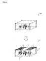
- Fig. 4 is a view for explaining an effect of the plant cultivation system 1.
- a conventional plant cultivation system 100 illustrated in the upper part of Fig. 4 there is a risk of slowing of growth of plants at end portions of a cultivation zone.
- plants placed at end portions of a cultivation zone are irradiated with illumination light promoting elongation growth.
- This promotes elongation growth of the plants placed at the end portions of the cultivation zone, thereby allowing leaves of the plants to be closer to the elongation promoting illuminating section 2.
- This promotes photosynthesis of these plants.
- it is possible to uniformly grow plants in a cultivation zone.
- Fig. 5 is a view illustrating a configuration of a plant cultivation system 20 of the present embodiment.
- the plant cultivation system 20 of the present embodiment includes a spectrum transforming sheet (spectrum transforming section) 8 instead of the elongation promoting illuminating section 2.
- the spectrum transforming sheet 8 is provided at end portions of a cultivation zone below a standard illuminating section 3 (an illumination light emission side of the standard illuminating section 3).
- the spectrum transforming sheet 8 converts a spectrum of standard illumination light (indicated by the arrow 10) emitted from the standard illuminating section 3 so as to reduce R/FR of the standard illumination light.
- the illumination light thus converted (indicated by the arrow 9) has a similar spectrum to elongation promoting illumination light emitted from the elongation promoting illuminating section 2. This means that a combination of the standard illuminating section 3 and the spectrum transforming sheet 8 functions as an illuminating section having a similar function to the elongation promoting illuminating section 2.
- the spectrum transforming sheet 8 need not necessarily be provided in parallel with the standard illuminating section 3.
- the spectrum transforming sheet 8 may be provided so as to cover the strawberries 7.
- the spectrum transforming sheet 8 can be provided in any way, provided that plants that are being cultivated in an identical cultivation zone are irradiated with different types of illumination light that differ from each other in R/FR.
- a spectrum transforming sheet 8 which converts a spectrum of standard illumination light emitted from the standard illuminating section 3 (or the elongation promoting illuminating section 2) so as to increase R/FR of the standard illumination light is provided at a central portion of the standard illuminating section 3 (or the elongation promoting illuminating section 2). Also according to this arrangement, R/FR of the illumination light with which end portions of the cultivation zone becomes relatively small.
- the spectrum transforming sheet 8 which increases R/FR can be, for example, Megacool (Registered Trademark) produced by MKV Dream Co., Ltd. or a pink sheet produced by Material Science Nagano.
- Fig. 6 is a view illustrating modifications of the elongation promoting illuminating section 2 and the standard illuminating section 3.
- the elongation promoting illuminating section 2 and the standard illuminating section 3 each may have a combination of red LEDs 11 emitting light having a peak in a red wavelength region and far-red LEDs 12 emitting light having a peak in a far-red wavelength region.
- R/FR of the elongation promoting illumination light may be made different from that of the standard illumination light by causing a ratio (disposition pattern) of the red LEDs 11 and the far-red LEDs 12 in the elongation promoting illuminating section 2 to be different from that in the standard illuminating section 3.
- R/FR of the elongation promoting illumination light may be made different from that of the standard illumination light by driving the LEDs of the elongation promoting illuminating section 2 and the LEDs of the standard illuminating section 3 under respective different driving conditions.
- the standard illuminating section 3 and the elongation promoting illuminating section 2 may have a combination of the red LEDs 11 and the far-red LEDs 12.
- a diffusion plate may be provided on an illumination light emission side of the elongation promoting illuminating section 2 and the standard illuminating section 3. This is to prevent occurrence of luminance unevenness, which can occur because LEDs (the red LEDs 11) emitting red light are different from LEDs (the far-red LEDs 12) emitting far-red light.
- irradiating strawberries with far-red light promotes enlargement etc. of the strawberries and as a result increases yield. This means that irradiating strawberries with far-red light emitted from the far-red LEDs 12 also produces an effect of increasing yield.
- Fig. 7 is a view illustrating a configuration of a plant cultivation device (plant cultivation system) 40 of the present embodiment.
- Fig. 8 is a top perspective view illustrating how illuminating sections are disposed in the plant cultivation device 40.
- the plant cultivation device 40 is a small plant cultivation device including a glass window (observation window) 41 through which the strawberries 7 can be observed from an outside.
- the plant cultivation device 40 includes other necessary equipment necessary for plant cultivation such as an air conditioner and an air blower, they are not directly related to the features of the present invention, and therefore are not described.
- the strawberries 7 are placed on a shelf board 42 provided inside a cultivation space 44, which is air-conditioned.
- a cultivation zone is a top surface of the shelf board 42.
- the cultivation space 44 defined by the plant cultivation device 40 can be regarded as a single cultivation zone.
- a standard illuminating section 3 and an elongation inhibiting illuminating section (first illuminating section) 43 are provided above the shelf board 42.
- the elongation inhibiting illuminating section 43 emits elongation inhibiting illumination light which has larger R/FR than standard illumination light emitted from the standard illuminating section 3.
- Types, circuit configurations, driving methods of LEDs of the standard illuminating section 3 and the elongation inhibiting illuminating section 43, and a method for adjusting R/FR of the illumination light can be similar to those of the embodiments above.
- a relative positional relationship between a region irradiated by the elongation inhibiting illuminating section 43 and a region irradiated by the standard illuminating section 3 is determined based on from which direction plants in the cultivation zone are observed.
- the standard illuminating section 3 is disposed on a side close to the glass window 41, which is an observation window, and the elongation promoting illuminating section 2 is disposed on a side far from the glass window 41. Accordingly, elongation growth of strawberries 7 on the side close to an observer 50 is suppressed as compared with strawberries 7 on the side far from the observer 50.
- the strawberries 7 be within the frame of the glass window 41.
- the strawberries 7 are cultivated without controlling their growth, it is highly likely that leaf stalks of the strawberries 7 will become too long to be within the frame of the glass window 41.
- the present invention can be expressed as follows.
- a ratio of red light and far-red light in the illumination light emitted from the first illuminating section is different from that in the illumination light emitted from the second illuminating section.
- a ratio of red light and far-red light in the first illumination light is different from that in the second illumination light.
- a smaller ratio (R/FR) of red light (R) and far-red light (FR) results in promotion of elongation growth. Conversely, larger R/FR results in suppression of elongation growth. Accordingly, a plant irradiated with the first illumination light and a plant irradiated with the second illumination light are different in degree of elongation growth.
- elongation growth of a plant that is being cultivated in a specific region of a cultivation zone can be selectively promoted or suppressed so as to be different from that of a plant that is being cultivated in another region of the cultivation zone.
- the illuminating device may be preferably arranged such that the first illuminating section and the second illuminating section each include a light source for emitting the illumination light containing a red light component and a far-red light component; and the ratio in a light emission spectrum of the light source provided in the first illuminating section is different from that in a light emission spectrum of the light source provided in the second illuminating section.
- the light source (first light source) provided in the first illuminating section and the light source (second light source) provided in the second illuminating section emit different types of illumination light each of which contains a red light component and a far-red light component and which have different light emission spectra with different R/FR.
- R/FR of the first illumination light can be made different from that of the second illumination light.
- the illuminating device may be preferably arranged such that the first illuminating section and the second illuminating section each include a red light source for emitting red light and a far-red light source for emitting far-red light; and the ratio in the illumination light emitted from the first illuminating section is made different from that in the illumination light emitted from the second illuminating section by causing a pattern in which the red light source and the far-red light source are disposed in the first illuminating section to be different from that in the second illuminating section.
- the first illuminating section and the second illuminating section are different from each other in pattern in which the red light source and the far-red light source are disposed, so that R/FR of the first illumination light is different from that of the second illumination light.
- the illuminating device may be arranged such that the first illuminating section and the second illuminating section each include a light source; the light source of the first illuminating section and the light source of the second illuminating section are same in type; and the ratio in the illumination light emitted from the light source provided in the first illuminating section is made different from that in the illumination light emitted from the light source provided in the second illuminating section by driving the light source provided in the first illuminating section and the light source provided in the second illuminating section under respective different driving conditions.
- the first light source provided in the first illuminating section and the second light source provided in the second illuminating section are of the same type, but R/FR of illumination light emitted from the first light source is made different from that of illumination light emitted from the second light source by driving first light source and the second light source under respective different driving conditions.
- the illuminating device may be arranged such that the first illuminating section includes a light source and a spectrum transforming section which generates the illumination light by converting a spectrum of light emitted from the light source.
- a spectrum of light emitted from the first light source provided in the first illuminating section is converted by the spectrum transforming section, and light thus converted is used as illumination light.
- the illuminating device may be arranged such that the first illuminating section irradiates an end portion of the cultivation zone with the illumination light; and the second illuminating section irradiates a different region of the cultivation zone with the illumination light.
- the end portion and the other region of the cultivation zone are different in R/FR of illumination light. Because growth of plants in an end portion of a cultivation zone is sometimes delayed as compared with the other region, it is possible to control elongation growth of the plants at the end portion of the cultivation zone by making a difference in R/FR between the end portion and the other region of the cultivation zone. Conversely, it is also possible to control elongation growth of plants at the region other than the end portion of the cultivation zone.
- the illuminating device may be arranged such that the cultivation zone is a zone for observation; and a relative positional relationship between a region irradiated with the illumination light by the first illuminating section and a region irradiated with the illumination light by the second illuminating section is determined based on from which direction the plant in the cultivation zone is observed.
- a relative positional relationship between a region irradiated with the first illumination light and a region irradiated with the second illumination light is determined based on from which direction the plants that are cultivated in the cultivation zone are observed.
- the illuminating device may be arranged such that the light source is a package in which a light source for emitting red light and a light source for emitting far-red light are contained.
- the illuminating device may be arranged such that the light source includes a light source for emitting red light and a light source for emitting far-red light that are individually packaged.
- the illuminating device may be arranged such that the light source includes a light-emitting diode.
- a light-emitting diode as a light source makes it possible to provide an illuminating device with a longer lifetime and less energy consumption.
- a plant cultivation system including the illuminating device for plant cultivation is encompassed within the technical scope of the present invention.
- the present invention is applicable as a plant cultivation device and a plant cultivation system in which growth of a plant is preferably controlled, and as an illuminating device provided in the plant cultivation device and the plant cultivation system.
Landscapes
- Life Sciences & Earth Sciences (AREA)
- Biodiversity & Conservation Biology (AREA)
- Botany (AREA)
- Ecology (AREA)
- Forests & Forestry (AREA)
- Environmental Sciences (AREA)
- Cultivation Of Plants (AREA)
Applications Claiming Priority (2)
| Application Number | Priority Date | Filing Date | Title |
|---|---|---|---|
| JP2011218365 | 2011-09-30 | ||
| PCT/JP2012/070858 WO2013046989A1 (ja) | 2011-09-30 | 2012-08-16 | 植物栽培用照明装置、植物栽培システムおよび植物栽培方法 |
Publications (2)
| Publication Number | Publication Date |
|---|---|
| EP2761997A1 true EP2761997A1 (de) | 2014-08-06 |
| EP2761997A4 EP2761997A4 (de) | 2015-04-29 |
Family
ID=47995040
Family Applications (1)
| Application Number | Title | Priority Date | Filing Date |
|---|---|---|---|
| EP12837315.6A Withdrawn EP2761997A4 (de) | 2011-09-30 | 2012-08-16 | Beleuchtungsvorrichtung für eine pflanzenzucht, pflanzenzuchtsystem und pflanzenzuchtverfahren |
Country Status (3)
| Country | Link |
|---|---|
| EP (1) | EP2761997A4 (de) |
| CN (1) | CN103841818B (de) |
| WO (1) | WO2013046989A1 (de) |
Cited By (1)
| Publication number | Priority date | Publication date | Assignee | Title |
|---|---|---|---|---|
| US10959381B2 (en) | 2015-03-31 | 2021-03-30 | Signify Holding B.V. | Systems and methods of illuminating plants |
Families Citing this family (6)
| Publication number | Priority date | Publication date | Assignee | Title |
|---|---|---|---|---|
| CN106211459A (zh) * | 2016-07-28 | 2016-12-07 | 厦门桑奈特光电科技有限公司 | 一种高效大波段生物刺激装置 |
| CN109479554B (zh) * | 2017-09-08 | 2021-10-12 | 松下知识产权经营株式会社 | 植物栽培装置 |
| CN109006232A (zh) * | 2018-05-04 | 2018-12-18 | 铜仁市万山区恒利达种养殖有限公司 | 一种瓠子栽培方法 |
| US11547060B2 (en) * | 2018-08-28 | 2023-01-10 | Seoul Viosys Co., Ltd. | Plant cultivation device and method for culturing plant |
| CN110278630B (zh) * | 2019-05-22 | 2022-09-27 | 杭州极致光生物照明有限公司 | 光谱调色照明方法、装置及其水族箱灯具 |
| JP2023049336A (ja) * | 2021-09-29 | 2023-04-10 | トヨタ紡織株式会社 | 植物栽培方法及び植物栽培装置 |
Family Cites Families (9)
| Publication number | Priority date | Publication date | Assignee | Title |
|---|---|---|---|---|
| JPH0260527A (ja) * | 1988-08-24 | 1990-03-01 | Matsushita Electric Ind Co Ltd | 植物の栽培方法及び栽培装置 |
| US5269093A (en) * | 1990-11-30 | 1993-12-14 | Matsushita Electric Industrial Co., Ltd. | Method and apparatus for controlling plant growth with artificial light |
| JPH0638635A (ja) * | 1991-12-05 | 1994-02-15 | Nippon Soda Co Ltd | 波長変換資材 |
| JP2002272271A (ja) * | 2001-03-15 | 2002-09-24 | Takagi Kogyo Kk | 植物等栽培用人工光源ユニット |
| JP2003123699A (ja) * | 2001-10-19 | 2003-04-25 | Manabu Nitoda | 光触媒作用を活性化する方法及び光触媒放電管、並びにこの原理を用いた製品 |
| JP4081648B2 (ja) * | 2001-11-28 | 2008-04-30 | 東芝ライテック株式会社 | 電照装置 |
| CN201225533Y (zh) * | 2008-05-26 | 2009-04-22 | 中国农业科学院农业环境与可持续发展研究所 | 一种组培使用的管状led光源装置 |
| JP2011097900A (ja) * | 2009-11-09 | 2011-05-19 | Sharp Corp | 植物育成用光源装置及び植物育成装置 |
| CN102182965B (zh) * | 2011-04-27 | 2012-11-14 | 浙江农林大学 | 四色光led组合补光灯 |
-
2012
- 2012-08-16 WO PCT/JP2012/070858 patent/WO2013046989A1/ja not_active Ceased
- 2012-08-16 EP EP12837315.6A patent/EP2761997A4/de not_active Withdrawn
- 2012-08-16 CN CN201280047856.3A patent/CN103841818B/zh not_active Expired - Fee Related
Cited By (1)
| Publication number | Priority date | Publication date | Assignee | Title |
|---|---|---|---|---|
| US10959381B2 (en) | 2015-03-31 | 2021-03-30 | Signify Holding B.V. | Systems and methods of illuminating plants |
Also Published As
| Publication number | Publication date |
|---|---|
| EP2761997A4 (de) | 2015-04-29 |
| CN103841818B (zh) | 2016-10-19 |
| CN103841818A (zh) | 2014-06-04 |
| WO2013046989A1 (ja) | 2013-04-04 |
Similar Documents
| Publication | Publication Date | Title |
|---|---|---|
| EP2761997A1 (de) | Beleuchtungsvorrichtung für eine pflanzenzucht, pflanzenzuchtsystem und pflanzenzuchtverfahren | |
| CN103476243B (zh) | 光照装置、草莓栽培系统和草莓栽培方法 | |
| KR100944359B1 (ko) | 식물 재배용 다광원 조명장치 및 이를 이용한 식물 재배 방법 | |
| KR101481538B1 (ko) | Led 식물 생육장치 | |
| EP2946654B1 (de) | Verfahren zur kultivierung von obst oder gemüse | |
| EP2761995B1 (de) | Pflanzenzuchtlampe und Pflanzenzuchtverfahren damit | |
| EP2962547B1 (de) | Verfahren zur züchtung von blatt-und-stengel-pflanzen und lichtquellenvorrichtung zur züchtung von blatt-und-stengel-pflanzen | |
| EP3127421B1 (de) | Beleuchtungsvorrichtung für pflanzenwachstum und pflanzenzuchtverfahren | |
| US20120198762A1 (en) | Spectural specific horticulture apparatus | |
| JP2012165665A (ja) | 照明装置、イチゴ栽培システムおよびイチゴ栽培方法 | |
| CN103574348B (zh) | 照明装置、植物栽培系统以及植物栽培方法 | |
| JP5723900B2 (ja) | 植物栽培方法 | |
| JP2014147375A (ja) | 植物栽培方法 | |
| JP5723903B2 (ja) | 植物栽培方法 | |
| KR101414473B1 (ko) | 상,하부 성장 촉진램프를 이용한 식물 재배방법 및 장치 | |
| KR20130052306A (ko) | 식물 조명장치 | |
| JP5723901B2 (ja) | 植物栽培方法 | |
| WO2012090897A1 (ja) | 色素蓄積促進システム、イオン発生装置および色素蓄積促進方法 | |
| JP5723902B2 (ja) | 植物栽培方法 | |
| KR101290801B1 (ko) | 식물 재배용 광원 및 이를 이용한 식물 재배 장치 | |
| JP5376667B2 (ja) | 花卉の育苗方法および育苗システム | |
| JP7578302B2 (ja) | 植物栽培装置 | |
| KR20220037078A (ko) | 식물생장조명장치 | |
| Yen et al. | Tissue culture of Anoectochilus Formosanus Hayata by combining fluorescent lamp and R-LEDs as light sources | |
| JP2023035491A (ja) | イネ科植物の育成方法及びイネ科植物育成用装置 |
Legal Events
| Date | Code | Title | Description |
|---|---|---|---|
| PUAI | Public reference made under article 153(3) epc to a published international application that has entered the european phase |
Free format text: ORIGINAL CODE: 0009012 |
|
| 17P | Request for examination filed |
Effective date: 20140328 |
|
| AK | Designated contracting states |
Kind code of ref document: A1 Designated state(s): AL AT BE BG CH CY CZ DE DK EE ES FI FR GB GR HR HU IE IS IT LI LT LU LV MC MK MT NL NO PL PT RO RS SE SI SK SM TR |
|
| DAX | Request for extension of the european patent (deleted) | ||
| RA4 | Supplementary search report drawn up and despatched (corrected) |
Effective date: 20150327 |
|
| RIC1 | Information provided on ipc code assigned before grant |
Ipc: A01G 7/04 20060101ALI20150323BHEP Ipc: A01G 7/00 20060101AFI20150323BHEP |
|
| STAA | Information on the status of an ep patent application or granted ep patent |
Free format text: STATUS: EXAMINATION IS IN PROGRESS |
|
| 17Q | First examination report despatched |
Effective date: 20171026 |
|
| STAA | Information on the status of an ep patent application or granted ep patent |
Free format text: STATUS: THE APPLICATION HAS BEEN WITHDRAWN |
|
| RAP1 | Party data changed (applicant data changed or rights of an application transferred) |
Owner name: SHARP LIFE SCIENCE CORPORATION |
|
| 18W | Application withdrawn |
Effective date: 20180302 |