EP2761277B1 - Systèmes optiques d'analyse biologique - Google Patents
Systèmes optiques d'analyse biologique Download PDFInfo
- Publication number
- EP2761277B1 EP2761277B1 EP12783710.2A EP12783710A EP2761277B1 EP 2761277 B1 EP2761277 B1 EP 2761277B1 EP 12783710 A EP12783710 A EP 12783710A EP 2761277 B1 EP2761277 B1 EP 2761277B1
- Authority
- EP
- European Patent Office
- Prior art keywords
- filter
- optical
- emission
- lens
- instrument
- Prior art date
- Legal status (The legal status is an assumption and is not a legal conclusion. Google has not performed a legal analysis and makes no representation as to the accuracy of the status listed.)
- Active
Links
- 230000003287 optical effect Effects 0.000 title claims description 200
- 238000004458 analytical method Methods 0.000 title claims description 4
- 239000000523 sample Substances 0.000 claims description 152
- 230000005284 excitation Effects 0.000 claims description 80
- 239000012472 biological sample Substances 0.000 claims description 40
- 230000005540 biological transmission Effects 0.000 claims description 18
- 230000005670 electromagnetic radiation Effects 0.000 claims description 11
- 238000011529 RT qPCR Methods 0.000 claims description 4
- 230000008859 change Effects 0.000 claims description 4
- 238000003753 real-time PCR Methods 0.000 claims description 3
- 230000000295 complement effect Effects 0.000 claims description 2
- 239000004065 semiconductor Substances 0.000 claims description 2
- 238000001228 spectrum Methods 0.000 claims 2
- 230000004075 alteration Effects 0.000 description 26
- 238000000034 method Methods 0.000 description 20
- 239000007850 fluorescent dye Substances 0.000 description 19
- 230000005855 radiation Effects 0.000 description 19
- 210000004027 cell Anatomy 0.000 description 18
- 230000008569 process Effects 0.000 description 16
- 239000000758 substrate Substances 0.000 description 16
- 238000012545 processing Methods 0.000 description 14
- 238000013461 design Methods 0.000 description 11
- 230000003595 spectral effect Effects 0.000 description 10
- 238000006243 chemical reaction Methods 0.000 description 9
- 238000003752 polymerase chain reaction Methods 0.000 description 9
- 238000012360 testing method Methods 0.000 description 9
- 239000000975 dye Substances 0.000 description 8
- 239000000463 material Substances 0.000 description 7
- 238000002474 experimental method Methods 0.000 description 6
- 238000007847 digital PCR Methods 0.000 description 5
- 229910052736 halogen Inorganic materials 0.000 description 5
- 150000002367 halogens Chemical class 0.000 description 5
- 238000000429 assembly Methods 0.000 description 4
- 230000000712 assembly Effects 0.000 description 4
- 238000005286 illumination Methods 0.000 description 4
- 108091028043 Nucleic acid sequence Proteins 0.000 description 3
- 239000006117 anti-reflective coating Substances 0.000 description 3
- 230000005499 meniscus Effects 0.000 description 3
- 108090000623 proteins and genes Proteins 0.000 description 3
- 108090000790 Enzymes Proteins 0.000 description 2
- 102000004190 Enzymes Human genes 0.000 description 2
- 230000008901 benefit Effects 0.000 description 2
- 238000005842 biochemical reaction Methods 0.000 description 2
- 239000000969 carrier Substances 0.000 description 2
- 238000000576 coating method Methods 0.000 description 2
- 238000010276 construction Methods 0.000 description 2
- 238000012937 correction Methods 0.000 description 2
- 230000007423 decrease Effects 0.000 description 2
- 238000001514 detection method Methods 0.000 description 2
- 238000003205 genotyping method Methods 0.000 description 2
- 238000009396 hybridization Methods 0.000 description 2
- 238000003384 imaging method Methods 0.000 description 2
- 238000012986 modification Methods 0.000 description 2
- 230000004048 modification Effects 0.000 description 2
- 239000002773 nucleotide Substances 0.000 description 2
- 125000003729 nucleotide group Chemical group 0.000 description 2
- 230000009467 reduction Effects 0.000 description 2
- 230000004044 response Effects 0.000 description 2
- 238000012163 sequencing technique Methods 0.000 description 2
- 108091032973 (ribonucleotides)n+m Proteins 0.000 description 1
- 206010010071 Coma Diseases 0.000 description 1
- 108091034117 Oligonucleotide Proteins 0.000 description 1
- XUIMIQQOPSSXEZ-UHFFFAOYSA-N Silicon Chemical compound [Si] XUIMIQQOPSSXEZ-UHFFFAOYSA-N 0.000 description 1
- JLCPHMBAVCMARE-UHFFFAOYSA-N [3-[[3-[[3-[[3-[[3-[[3-[[3-[[3-[[3-[[3-[[3-[[5-(2-amino-6-oxo-1H-purin-9-yl)-3-[[3-[[3-[[3-[[3-[[3-[[5-(2-amino-6-oxo-1H-purin-9-yl)-3-[[5-(2-amino-6-oxo-1H-purin-9-yl)-3-hydroxyoxolan-2-yl]methoxy-hydroxyphosphoryl]oxyoxolan-2-yl]methoxy-hydroxyphosphoryl]oxy-5-(5-methyl-2,4-dioxopyrimidin-1-yl)oxolan-2-yl]methoxy-hydroxyphosphoryl]oxy-5-(6-aminopurin-9-yl)oxolan-2-yl]methoxy-hydroxyphosphoryl]oxy-5-(6-aminopurin-9-yl)oxolan-2-yl]methoxy-hydroxyphosphoryl]oxy-5-(6-aminopurin-9-yl)oxolan-2-yl]methoxy-hydroxyphosphoryl]oxy-5-(6-aminopurin-9-yl)oxolan-2-yl]methoxy-hydroxyphosphoryl]oxyoxolan-2-yl]methoxy-hydroxyphosphoryl]oxy-5-(5-methyl-2,4-dioxopyrimidin-1-yl)oxolan-2-yl]methoxy-hydroxyphosphoryl]oxy-5-(4-amino-2-oxopyrimidin-1-yl)oxolan-2-yl]methoxy-hydroxyphosphoryl]oxy-5-(5-methyl-2,4-dioxopyrimidin-1-yl)oxolan-2-yl]methoxy-hydroxyphosphoryl]oxy-5-(5-methyl-2,4-dioxopyrimidin-1-yl)oxolan-2-yl]methoxy-hydroxyphosphoryl]oxy-5-(6-aminopurin-9-yl)oxolan-2-yl]methoxy-hydroxyphosphoryl]oxy-5-(6-aminopurin-9-yl)oxolan-2-yl]methoxy-hydroxyphosphoryl]oxy-5-(4-amino-2-oxopyrimidin-1-yl)oxolan-2-yl]methoxy-hydroxyphosphoryl]oxy-5-(4-amino-2-oxopyrimidin-1-yl)oxolan-2-yl]methoxy-hydroxyphosphoryl]oxy-5-(4-amino-2-oxopyrimidin-1-yl)oxolan-2-yl]methoxy-hydroxyphosphoryl]oxy-5-(6-aminopurin-9-yl)oxolan-2-yl]methoxy-hydroxyphosphoryl]oxy-5-(4-amino-2-oxopyrimidin-1-yl)oxolan-2-yl]methyl [5-(6-aminopurin-9-yl)-2-(hydroxymethyl)oxolan-3-yl] hydrogen phosphate Polymers Cc1cn(C2CC(OP(O)(=O)OCC3OC(CC3OP(O)(=O)OCC3OC(CC3O)n3cnc4c3nc(N)[nH]c4=O)n3cnc4c3nc(N)[nH]c4=O)C(COP(O)(=O)OC3CC(OC3COP(O)(=O)OC3CC(OC3COP(O)(=O)OC3CC(OC3COP(O)(=O)OC3CC(OC3COP(O)(=O)OC3CC(OC3COP(O)(=O)OC3CC(OC3COP(O)(=O)OC3CC(OC3COP(O)(=O)OC3CC(OC3COP(O)(=O)OC3CC(OC3COP(O)(=O)OC3CC(OC3COP(O)(=O)OC3CC(OC3COP(O)(=O)OC3CC(OC3COP(O)(=O)OC3CC(OC3COP(O)(=O)OC3CC(OC3COP(O)(=O)OC3CC(OC3COP(O)(=O)OC3CC(OC3COP(O)(=O)OC3CC(OC3CO)n3cnc4c(N)ncnc34)n3ccc(N)nc3=O)n3cnc4c(N)ncnc34)n3ccc(N)nc3=O)n3ccc(N)nc3=O)n3ccc(N)nc3=O)n3cnc4c(N)ncnc34)n3cnc4c(N)ncnc34)n3cc(C)c(=O)[nH]c3=O)n3cc(C)c(=O)[nH]c3=O)n3ccc(N)nc3=O)n3cc(C)c(=O)[nH]c3=O)n3cnc4c3nc(N)[nH]c4=O)n3cnc4c(N)ncnc34)n3cnc4c(N)ncnc34)n3cnc4c(N)ncnc34)n3cnc4c(N)ncnc34)O2)c(=O)[nH]c1=O JLCPHMBAVCMARE-UHFFFAOYSA-N 0.000 description 1
- 230000001154 acute effect Effects 0.000 description 1
- 125000003275 alpha amino acid group Chemical group 0.000 description 1
- 230000003466 anti-cipated effect Effects 0.000 description 1
- 201000009310 astigmatism Diseases 0.000 description 1
- 239000011324 bead Substances 0.000 description 1
- 239000000872 buffer Substances 0.000 description 1
- -1 but not limited to Polymers 0.000 description 1
- 230000001413 cellular effect Effects 0.000 description 1
- 239000011248 coating agent Substances 0.000 description 1
- 239000003086 colorant Substances 0.000 description 1
- 150000001875 compounds Chemical class 0.000 description 1
- 238000009833 condensation Methods 0.000 description 1
- 230000005494 condensation Effects 0.000 description 1
- 230000001351 cycling effect Effects 0.000 description 1
- 230000003247 decreasing effect Effects 0.000 description 1
- 230000001419 dependent effect Effects 0.000 description 1
- 239000003599 detergent Substances 0.000 description 1
- 230000000694 effects Effects 0.000 description 1
- 238000005516 engineering process Methods 0.000 description 1
- 238000001704 evaporation Methods 0.000 description 1
- 230000008020 evaporation Effects 0.000 description 1
- 230000002349 favourable effect Effects 0.000 description 1
- 239000011521 glass Substances 0.000 description 1
- 230000002209 hydrophobic effect Effects 0.000 description 1
- 238000002955 isolation Methods 0.000 description 1
- 239000006193 liquid solution Substances 0.000 description 1
- 229920002521 macromolecule Polymers 0.000 description 1
- 238000012544 monitoring process Methods 0.000 description 1
- 210000004940 nucleus Anatomy 0.000 description 1
- 108091033319 polynucleotide Proteins 0.000 description 1
- 239000002157 polynucleotide Substances 0.000 description 1
- 102000040430 polynucleotide Human genes 0.000 description 1
- 229920001184 polypeptide Polymers 0.000 description 1
- 108090000765 processed proteins & peptides Proteins 0.000 description 1
- 102000004196 processed proteins & peptides Human genes 0.000 description 1
- 102000004169 proteins and genes Human genes 0.000 description 1
- 230000000717 retained effect Effects 0.000 description 1
- 238000007789 sealing Methods 0.000 description 1
- 229910052710 silicon Inorganic materials 0.000 description 1
- 239000010703 silicon Substances 0.000 description 1
- 238000005549 size reduction Methods 0.000 description 1
- 239000000126 substance Substances 0.000 description 1
- 238000012546 transfer Methods 0.000 description 1
- 210000004881 tumor cell Anatomy 0.000 description 1
- 229910052724 xenon Inorganic materials 0.000 description 1
- FHNFHKCVQCLJFQ-UHFFFAOYSA-N xenon atom Chemical compound [Xe] FHNFHKCVQCLJFQ-UHFFFAOYSA-N 0.000 description 1
Images


Classifications
-
- G—PHYSICS
- G01—MEASURING; TESTING
- G01N—INVESTIGATING OR ANALYSING MATERIALS BY DETERMINING THEIR CHEMICAL OR PHYSICAL PROPERTIES
- G01N21/00—Investigating or analysing materials by the use of optical means, i.e. using sub-millimetre waves, infrared, visible or ultraviolet light
- G01N21/62—Systems in which the material investigated is excited whereby it emits light or causes a change in wavelength of the incident light
- G01N21/63—Systems in which the material investigated is excited whereby it emits light or causes a change in wavelength of the incident light optically excited
- G01N21/64—Fluorescence; Phosphorescence
- G01N21/6486—Measuring fluorescence of biological material, e.g. DNA, RNA, cells
-
- G—PHYSICS
- G01—MEASURING; TESTING
- G01N—INVESTIGATING OR ANALYSING MATERIALS BY DETERMINING THEIR CHEMICAL OR PHYSICAL PROPERTIES
- G01N21/00—Investigating or analysing materials by the use of optical means, i.e. using sub-millimetre waves, infrared, visible or ultraviolet light
- G01N21/62—Systems in which the material investigated is excited whereby it emits light or causes a change in wavelength of the incident light
- G01N21/63—Systems in which the material investigated is excited whereby it emits light or causes a change in wavelength of the incident light optically excited
- G01N21/64—Fluorescence; Phosphorescence
- G01N21/645—Specially adapted constructive features of fluorimeters
- G01N21/6452—Individual samples arranged in a regular 2D-array, e.g. multiwell plates
-
- G—PHYSICS
- G01—MEASURING; TESTING
- G01N—INVESTIGATING OR ANALYSING MATERIALS BY DETERMINING THEIR CHEMICAL OR PHYSICAL PROPERTIES
- G01N21/00—Investigating or analysing materials by the use of optical means, i.e. using sub-millimetre waves, infrared, visible or ultraviolet light
- G01N21/62—Systems in which the material investigated is excited whereby it emits light or causes a change in wavelength of the incident light
- G01N21/63—Systems in which the material investigated is excited whereby it emits light or causes a change in wavelength of the incident light optically excited
- G01N21/64—Fluorescence; Phosphorescence
- G01N21/6428—Measuring fluorescence of fluorescent products of reactions or of fluorochrome labelled reactive substances, e.g. measuring quenching effects, using measuring "optrodes"
-
- G—PHYSICS
- G01—MEASURING; TESTING
- G01N—INVESTIGATING OR ANALYSING MATERIALS BY DETERMINING THEIR CHEMICAL OR PHYSICAL PROPERTIES
- G01N21/00—Investigating or analysing materials by the use of optical means, i.e. using sub-millimetre waves, infrared, visible or ultraviolet light
- G01N21/62—Systems in which the material investigated is excited whereby it emits light or causes a change in wavelength of the incident light
- G01N21/63—Systems in which the material investigated is excited whereby it emits light or causes a change in wavelength of the incident light optically excited
- G01N21/64—Fluorescence; Phosphorescence
- G01N21/645—Specially adapted constructive features of fluorimeters
- G01N2021/6463—Optics
- G01N2021/6471—Special filters, filter wheel
-
- G—PHYSICS
- G01—MEASURING; TESTING
- G01N—INVESTIGATING OR ANALYSING MATERIALS BY DETERMINING THEIR CHEMICAL OR PHYSICAL PROPERTIES
- G01N21/00—Investigating or analysing materials by the use of optical means, i.e. using sub-millimetre waves, infrared, visible or ultraviolet light
- G01N21/62—Systems in which the material investigated is excited whereby it emits light or causes a change in wavelength of the incident light
- G01N21/63—Systems in which the material investigated is excited whereby it emits light or causes a change in wavelength of the incident light optically excited
- G01N21/64—Fluorescence; Phosphorescence
- G01N21/645—Specially adapted constructive features of fluorimeters
- G01N2021/6463—Optics
- G01N2021/6478—Special lenses
-
- G—PHYSICS
- G01—MEASURING; TESTING
- G01N—INVESTIGATING OR ANALYSING MATERIALS BY DETERMINING THEIR CHEMICAL OR PHYSICAL PROPERTIES
- G01N2201/00—Features of devices classified in G01N21/00
- G01N2201/06—Illumination; Optics
- G01N2201/062—LED's
Definitions
- the present invention relates generally to instruments for observing, testing, and/or analyzing one or more biological samples, and more specifically to systems, devices, and methods comprising an optical system for observing, testing, and/or analyzing one or more biological samples.
- Optical systems for biological and biochemical reactions have been used to monitor, measure, and/or analyze such reactions in real time. Such systems are commonly used in sequencing, genotyping, polymerase chain reaction (PCR), and other biochemical reactions to monitor the progress and provide quantitative data.
- PCR polymerase chain reaction
- an optical excitation beam may be used in real-time PCR (qPCR) reactions to illuminate hybridization probes or molecular beacons to provide fluorescent signals indicative of the amount of a target gene or other nucleotide sequence.
- qPCR real-time PCR
- dPCR digital PCR
- US 2006/0006067 A1 discloses an optical lens system and method for microfluidic devices.
- US 2008/0117425 A1 discloses a hexagonal site line scanning method and system.
- GB 2197499 A discloses a high spatial and time resolution measuring apparatus for optically measuring a fine area in an object, such as a tumor cell mixed into normal cells.
- JP H09-243813 discloses a filter wheel provided with chromatic aberration compensating lenses.
- an instrument for biological analysis as recited in claim 1 below.
- the term "light” means electromagnetic radiation within the visible waveband, for example, electromagnetic radiation with a wavelength in a vacuum that is within a range from 390 nanometers to 780 nanometers.
- the term “infrared” means electromagnetic radiation having a wavelength within a range of 0.74 micrometer to 300 micrometers.
- optical power means the ability of a lens or optic to converge or diverge light to provide a focus (real or virtual) when disposed within air.
- focal length means the reciprocal of the optical power.
- diffractive power or “diffractive optical power” means the power of a lens or optic, or portion thereof, attributable to diffraction of incident light into one or more diffraction orders. Except where noted otherwise, the optical power of a lens, optic, or optical element is from a reference plane associated with the lens or optic (e.g., a principal plane of an optic).
- the term "about zero” or “approximately zero” means within 0.1 of the unit of measure being referred to, unless otherwise noted.
- “about zero meters” means less than or equal to 0.1 meters, if the dimension may only reasonably have a positive value, or within a range of -0.1 meters to +0.1 meters, if the dimension may have either a positive or negative value.
- the terms “about” or “approximately”, as used herein, means within 0.1 Diopter.
- the phrase “about zero Diopter” or “approximately zero Diopter” means within a range of -0.1 Diopter to +0.1 Diopters.
- a system or instrument 1000 for biological analysis comprises an optical system 100.
- system or instrument 1000 additionally comprises a sample block or processing system 200 and/or an electronic processor, computer, or controller 300 configured to control, monitor, and/or receive data from optical system 100 and/or sample processing system 200.
- system or instrument 1000 may be a sequencing instrument, a polymerase chain reaction (PCR) instrument (e.g., a real-time PCR (qPCR) instrument and/or digital PCR (dPCR) instrument), an instrument for providing genotyping information, or the like.
- PCR polymerase chain reaction
- qPCR real-time PCR
- dPCR digital PCR
- optical system 100 comprises an illumination or excitation source 110 providing one or more excitation beams 111 and an optical sensor 118 configured to receive one or more emission beams 119 from one or more biological samples 115.
- Optical system 100 also comprises an excitation optical system 120 and an emission optical system 125.
- Excitation optical system 120 is disposed along an excitation optical path 126 and is configured to direct the electromagnetic radiation or light from excitation source 110 to sample holder containing one or more biological samples.
- Emission optical system 125 is disposed along an emission optical path 128 and is configured to direct electromagnetic emissions from biological samples 115 to optical sensor 118, for example, one or more fluorescence signals produced at one or more wavelengths in response to the one or more excitation beams 111.
- Optical system 100 further comprises an emission filter assembly 130 comprising a plurality of filter components, elements, or modules 131 configured to interchangeably locate or move one or more of filter modules 131 into emission optical path 128.
- Optical system 100 may additionally comprise an excitation filter assembly 132 comprising a plurality of filter components, elements, or modules 133, wherein excitation filter assembly 132 is configured to interchangeably locate or move one or more of filter modules 133 into excitation optical path 126.
- Optical system 100 may further comprise a first optical element 152 configured to direct light to optical sensor 118, a second optical element 154 configured to direct excitation light to, and/or emission light from, the biological samples, a beamsplitter 160, and/or one or more optical windows 162.
- sample processing system 200 comprises a carrier or support frame 202 configured to receive a sample holder 204.
- Sample holder 204 comprises a plurality or array of cells 205 for containing a corresponding plurality or array of biological samples 115 that may be processed by sample processing system 200 and/or optical system 100.
- Cells 205 may be in the forms of sample wells, cavities, through-holes, or any other chamber type suitable containing and/or isolating the plurality of biological samples 115.
- sample cells 205 may be in the form of sample beads in a flow cell or discrete samples deposited on top of a substrate surface such as a glass or silicon substrate surface.
- sample holder 204 comprises 96 sample cells 205 that are in the form of 96 sample wells 209 configured to provide 96 isolated or distinct biological samples 115.
- sample holder 204 may comprise less than 96 well and samples, for example, 48 wells and samples, or may contain more than 96 wells, for example, 384 or more wells and samples.
- carrier 202 is configured to receive more than one sample holder 204 for simultaneous processing by sample processing system 200 and/or optical system 100.
- Sample processing system 200 may further comprise a block or assembly 210 for receiving sample holder 204.
- Block 210 may be thermal block including temperature control hardware for controlling or cycling the temperature of biological samples 115.
- Sample processor system 200 may further comprise a thermally controlled or heated lid 212 disposed about sample holder 204.
- Thermally controlled lid 212 may be configured to aid in controlling a thermal and/or humidity environment of biological samples 115 or sample holder 204, for example, to aid in preventing condensation from forming on samples 115 or optical elements of sample holder 204.
- system 200 includes a set of different types or configurations of block 210 and/or different types or configurations of thermally controlled lid 212, where each member of the set is configured for use with a different type or number of sample holders 204 or carriers 202.
- system 1000 may be additionally or alternatively configured to receive and process a sample holder 304 comprising a substrate 306 including a plurality of through-holes 309.
- through-holes 309 are configured to maintain isolated or distinct biological samples 315 by capillary forces, for example, by forming through-holes to have an appropriately small diameter and/or through the use of hydrophilic and/or hydrophobic materials or coatings.
- Substrate 306 may further comprise an alphanumeric 320, a barcode 322, and/or similar symbol for identification or processing purposes.
- sample holder 304 may further comprise an enclosure or case for protecting or sealing substrate 306 and the biological samples contained in through-holes 309.
- the case may comprise a base 324 and a cover 328 that are configured to seal substrate 306 between base 324 and cover 328, for example, to reduce or prevent evaporation of the biological samples.
- Cover 328 is made of a transmissive material and comprises a top surface 330 and an opposing bottom surface 332 for providing optical access to substrate 306.
- One or both surfaces 330, 332 may comprise an antireflective coating, for example, to reduce retro-reflections of light from excitation beam 111 back toward optical sensor 118.
- one or both surfaces 330, 332 may be disposed at an angle relative to a front surface of substrate 306, for example, to reduce retro-reflections of light from excitation beam 111 back toward optical sensor 118. Referring to FIG.
- one or more sample holders 304 may be retained by or mounted on a carrier 302 that is configured to be received by sample processing system 200.
- carrier 302 is configured to retain four or less sample holders 304. For clarity, not all the through-holes
- each through-hole 309 has a diameter of about 320 micrometers, a thickness of about 300 micrometer, and a volume of about 33 nanoliters.
- Through-holes 309 have a nominal spacing in the illustrated embodiment of about 500 micrometers center to center.
- optical system 100 may be configured to allow imaging and processing of biological samples contained in through-holes having such small diameters or volumes. Additionally or alternatively, system 1000 and/or optical system 100 is configured receive and process a sample holder 304 having smaller through-hole diameter and/or a smaller nominal spacing than in the illustrated embodiment of FIG. 5 .
- optical system 100 may be configured to allow system 1000 to receive and process a sample holder 304 comprising through-holes having a diameter that is less than or equal to 250 micrometer and/or a volume that is less than or equal to 5 nanoliters.
- optical system 100 may be configured to allow system 1000 to receive and process a sample holder 304 comprising through-holes having a diameter that is less than or equal to 150 micrometer and/or a volume that is less than or equal to one nanoliter.
- an initial sample or solution for a sample holder such as sample holders 204, 304, may be divided into hundreds, thousands, tens of thousands, hundreds of thousands, or even millions of reaction sites, each having a volume of, for example, a few nanoliters, about one nanoliter, or less than one nanoliter (e.g., 10's or 100's of picoliters or less).
- sample holders 204, 304 have a rectangular shape; however, other shapes may be used, such as a square or circular shape.
- a sample holder such as sample holder 304 has a square shape and an overall dimension of 15 millimeter by 15 millimeter.
- the sample holder may have an active area, region, or zone with a dimension of 13 millimeter by 13 millimeter.
- the terms "active area”, “active region”, or “active zone” mean a surface area, region, or zone of a sample holder, such as the sample holders 204 or 304, over which reaction regions, through-holes, or solution volumes are contained or distributed.
- the active area of sample holder 304 may be increased to 14 millimeter by 14 millimeter or larger, for example, a 15 millimeter by 15 millimeter substrate dimension.
- through-holes 309 may have a characteristic diameter of 320 micrometer and a pitch of 500 micrometers between adjacent through-holes. In other embodiments, through-holes 309 have a characteristic diameter of 75 micrometer and have a pitch of 125 micrometers between adjacent through-holes. In yet other embodiments, through-holes 309 have a characteristic diameter of that is less than or equal 75 micrometers, for example, a characteristic diameter that is less or equal to 60 micrometers or less or equal to 50 micrometers. In other embodiments, through-holes 309 have a characteristic diameter that is less than or equal to 20 micrometers, less than or equal to 10 micrometers, or less than or equal to 1 micrometer. The pitch between through-holes may be less than or equal to 125 micrometers, for example, less than or equal to 100 micrometers, less than or equal to 30 micrometers, or less than or equal to 10 micrometers.
- sample holder 304 comprises a substrate having a thickness between the opposing surfaces of sample holder 304 that is at or about 300 micrometer, wherein each through-hole 309 may have a volume of 1.3 nanoliter, 33 nanoliters, or somewhere between 1.3 nanoliter and 33 nanoliters.
- the volume of each through-holes 309 may be less than or equal to 1 nanoliter, for example, by decreasing the diameter of through-holes 309 and/or the thickness of sample holder 304 substrate.
- each through-holes 309 may have a volume that is less than or equal to 1 nanoliter, less than or equal to 100 picoliters, less than or equal to 30 picoliters, or less than or equal to 10 picoliters.
- the volume some or all of the through-holes 309 is in a range from 1 nanoliter to 20 nanoliters.
- the density of through-holes 309 is at least 100 through-holes per square millimeter. Higher densities are also anticipated. For example, a density of through-holes 309 may be greater than or equal to 150 through-holes per square millimeter, greater than or equal to 200 through-holes per square millimeter, greater than or equal to 500 through-holes per square millimeter, greater than or equal to 1,000 through-holes per square millimeter, or greater than or equal to 10,000 through-holes per square millimeter.
- all the through-holes 309 with an active area may be simultaneously imaged and analyzed by an optical system.
- active area comprises over 12,000 through-holes 309.
- active area comprises at least 25,000, at least 30,000, at least 100,000, or at least 1,000,000 through-holes.
- through-holes 309 comprise a first plurality of the through-holes characterized by a first characteristic diameter, thickness, or volume and a second plurality of the through-holes characterized by a second characteristic diameter, thickness, or volume that is different than the first characteristic diameter, thickness, or volume.
- Such variation in through-hole size or dimension may be used, for example, to simultaneously analyze two or more different nucleotide sequences that may have different concentrations.
- a variation in through-hole 104 size on a single substrate 304 may be used to increase the dynamic range of a process or experiment.
- sample holder 304 may comprise two or more subarrays of through-holes 309, where each group is characterized by a diameter or thickness that is different a diameter or thickness of the through-holes 309 of the other or remaining group(s). Each group may be sized to provide a different dynamic range of number count of a target polynucleotide.
- the subarrays may be located on different parts of substrate 304 or may be interspersed so that two or more subarrays extend over the entire active area of sample holder 304 or over a common portion of active area of sample holder 304.
- the through-holes 309 are tapered or chamfered over all or a portion of their walls.
- the use of a chamfer and/or a tapered through-holes have been found to reduce the average distance or total area between adjacent through-holes 309, without exceeding optical limitations for minimum spacing between solution sites or test samples. This results in a reduction in the amount liquid solution that is left behind on a surface of substrate 304 during a loading process. Thus, higher loading efficiency may be obtained, while still maintaining a larger effective spacing between adjacent solution sites or test samples for the optical system.
- system 1000 is configured to receive and process different types or numbers of block 210, carrier 202, and/or sample holder 204.
- system 1000 may be configured to receive and process different sample holders 204 having different numbers of wells 209.
- system 1000 may be configured to receive and process sample holders 204 containing 96 samples and sample holders 204 containing 48 wells and/or 384 well or/or more than 384 wells.
- system 1000 may be configured to receive and process different sample formats or container configurations.
- system 1000 may also be configured to receive and process one or more sample holders 304 comprising the plurality of through-holes 309.
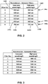
- system 1000 is configured to receive and process four different types of sample holders. Some of the characteristics of wells or through-holes used in these four sample holders are listed in Table 1 below. Table 1 . Characteristics of four sample holders according to an embodiment of the present invention. Sample Holder Sample Cell Type Number of Cells Characteristic Cell Volume Characteristic Cell Diameter A Well 96 200 microliters 5 millimeters B Well 384 50 microliters 3 millimeters c Cavity 384 2 microliters 3 millimeters D Through-hole 4 x 3072 0.033 microliters 0.35 millimeters
- optical sensor 118 may comprise one or more photodetectors or photosensors, for example, one or more photodiodes, photomultiplier tubes, or the like.
- optical sensor 118 may comprise a one-dimensional or two-dimensional photodetector array 164, such as a charge-coupled device (CCD), complementary metal-oxide-semiconductor (CMOS), or the like.
- CCD charge-coupled device
- CMOS complementary metal-oxide-semiconductor
- photodetector array 164 comprises a two dimensional array of photosensitive pixels defining photosensitive surface upon which an optical image or signal may be formed by emission optical system 125.
- Excitation source 110 may be a halogen lamp, a Xenon lamp, high-intensity discharge (HID) lamp, one or more light emitting diodes (LEDs), one or more laser, or the like.
- excitation source 110 comprises a plurality of light sources having different emission wavelength ranges to excite different fluorescent dyes in biological samples 115, for a example, a plurality of LED light sources having different colors or emission wavelength ranges.
- excitation filter assembly 132 may be omitted or may be incorporated for use with at least some of the different light sources to further limit the wavelength range of light or radiation reaching samples 115.
- excitation source 110 comprises one or more broadband or white light LED sources.
- excitation source 110 may comprise a high power, broadband source having at least 5 watts of total output optical power, at least 10 watts of output optical power, or at least 25 watts of output optical power.
- excitation filter assembly 132 may be incorporated to limit or define the spectral content of the radiation or light received by samples 115 and/or sample holder 204, 304.
- the spectral content of the broadband source 110 may be configured to favorably provide more energy over wavelength ranges that, for example, correspond to probes or dye molecules in samples 115 that are less efficient, are typically found lower concentrations, or otherwise require more photonic energy that other dyes contained in samples 115.
- excitation source 110 comprises a single broadband LED having a total optical power of greater than 10 watts over the spectral range produced by the LED.
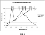
- the spectral output characteristics of such an excitation source is shown by the solid line in the graphs shown in FIG. 8 .
- the horizontal axis corresponds to the wavelength of radiation emitted by the LED excitation source 110, while the vertical axis is a relative output intensity.
- the "relative intensity" for the plot in FIG. 8 is a percentage value that is defined as 100 times the intensity measured at a given wavelength divided by the maximum intensity measured at any wavelength within range of wavelengths produced by the LED. For example, according to the plot in FIG.
- the measured intensity out of the LED at a wavelength of 450 nanometer is about 80 percent of the maximum intensity, where the maximum measured intensity occurs at an output wavelength of 457 nanometers.
- similar data for a halogen lamp used in a prior art system is also shown in FIG. 8 as dashed lines.
- the sets of double lines with numeral in between indicate the approximate transmission wavelength bands for the excitation filters shown in FIG. 3 .
- the characteristic cell diameter and volume of sample holder D is much smaller than that of sample holders A-C.
- a typical fluorescence signal produced by sample holder D is much smaller than a typical fluorescence signal produced by sample holders A-C under similar conditions, for example, when using biological samples containing similar concentrations of a biological test sample and/or a fluorescent probe or reference dye.
- the halogen excitation source shown in FIG. 8 may not provide sufficient intensity or power density for fluorescent probes or dyes excited by light in the wavelength range provided by filters 1-3 in FIG. 3 .
- fluorescent probes or dyes excited by light in the wavelength range provided by excitation filters 1, 2, and 4 in FIG. 3 are either more commonly used or are of greater importance than those excited by light in the wavelength range provided by filters 3, 5, and/or 6, for example, in the wavelength range provided by either filters 5 or 6.
- the dyes FAMTM VIC®, and ROXTM are used, which dyes are commercially available from Life Technologies in Carlsbad, CA.
- excitation filter 1 is used to excite the dye FAMTM
- excitation filter 2 may be used to excite the dye VIC®
- excitation filter 4 may be used to excite the dye ROXTM.
- an excitation source 110 comprising an LED source having spectral characteristics the same or similar to those shown in FIG. 8 has an unexpected benefit, even though (1) the spectral power or intensity of the LED source for fluorescent probes or dyes excited by light in the wavelength range provided by filters 5 and 6 is less than that for the halogen source shown in FIG.
- an LED source such as that characterized in FIG. 8 is able to provide enough excitation energy to the biological samples so that system 1000 is able to process the signals or images received by optical sensor 118.
- instrument or system 1000 can process biological samples to provide useful data using a broadband LED that produces light or radiation having a maximum intensity and/or power density at a wavelength that is less than 600 nanometers and/or that is less than 550 nanometers.
- instrument or system 1000 can provide useful PCR data (e.g., qPCR and/or dPCR data) using such a broadband LED, such as that represented in FIG. 8 .
- useful PCR data e.g., qPCR and/or dPCR data
- FIG. 8 a broadband LED
- the result is an instrument that can provide data, such as PCR data, over a wide range of sample sizes and sample holder or cell formats, for example, all the sample sizes and sample cell formats listed in Table 1.
- system 1000 includes an excitation source 110 comprising an LED having a spectral profile characterized by a maximum intensity or optical output power at a wavelength that is less than 550 or 600 nanometers and an intensity or optical output power that is less than 50 percent the maximum value at a wavelength of 650 nanometer and/or 670 nanometers.
- system 1000 includes an excitation source 110 comprising an LED having a spectral profile characterized by a maximum intensity or optical output power at a wavelength that is less than 550 or 600 nanometers and an intensity or optical output power that is less than 30 percent or less than 20 percent the maximum value at a wavelength of 650 nanometer and/or 670 nanometers.
- the system 1000 further comprise an emission optical system 125 that is able to provide useful biological data (e.g., PCR data) for sample cells having a diameter of less than 500 micrometer, less than 200 micrometers, or less than 100 micrometers that contain fluorescent probes or dye molecule that fluoresce at excitation wavelengths that are less than or equal to 560 nanometer, while also being able to provide useful biological data (e.g., PCR data) for sample cells having a diameter of greater than 2 millimeters or greater than 3 millimeters that contain fluorescent probes or dye molecule that fluoresce at excitation wavelengths that are greater than or equal to 620 nanometer or greater than or equal to 650 nanometers.
- useful biological data e.g., PCR data
- IR emissions from excitation source 110 are much lower than, for example, a halogen light source according to that shown in FIG. 8 .
- embodiments of the present invention provide reduced IR noise without the need extra optical element such as so-called "hot mirrors" to block IR emissions.
- the output intensity, power, or energy of excitation source 110 may be varied depending on a condition or variable value, for example, depending on the type of sample holder used, size of one or more reaction regions, experiment or run conditions of system or instrument 1000, experiment or run conditions of optical system 100, experiment or run conditions of sample processing system 200, or the like.
- excitation source 110 may be an LED light source in which the output intensity, power, or energy is varied depending on one or more of the conditions and/or variable values.
- the output intensity, power, or energy of the LED may be varied by adjusting or changing a current or voltage driving the LED, and/or by adjusting or changing a duty cycle of the LED.
- excitation source 110 may be an LED that is run at full output power, intensity, or energy - or at a higher power setting output power, intensity, or energy - when sample holder A from Table 1 is used.
- the LED may be run at a lower output power, intensity, or energy when a different sample holder is used, for example, sample holder B, C, or D from Table 1 is used.
- Lens 152 is configured to form an image on photodetector array 164, for example, by focusing collimated radiation entering from a particular direction to a spot or point, for example, to a diffraction limited spot or a nearly diffraction limited spot.
- Lens 152 may be a simple lens, such as a plano-convex lens, plano-concave lens, bi-convex lens, bi-concave lens, meniscus lens, or the like.
- lens 152 may comprise a compound lens such as a doublet lens or triplet lens that may, for example, comprise different lens materials selected to correct or reduce a chromatic aberration.
- lens 152 comprises system of lenses such as a camera lens system or microscope objective, for example, a commercially available camera lens.
- the camera lens system may be a commercially available camera lens comprising a conventional lens system design, for example, a double Gauss design, a Cooke triplet design, retrofocus lens design (e.g., Distagon lens design), a Tessar lens design, or the like.
- Lens 154 may be a single field lens, for example, configured to provide a telecentric optical system when combined with the remaining optical elements of excitation optical system 120 and/or emission optical system 125.
- lens 154 may be a simple lens, such as a plano-convex lens, plano-concave lens, bi-convex lens, bi-concave lens, meniscus lens, or the like.
- lens 152 may comprise a doublet lens or triplet lens, for example, comprising different lens material to correct for a chromatic aberration.
- lens 154 may comprise a Fresnel lens or a diffractive optical element, surface, or pattern.
- lens 154 may comprise a lens system, for example, a field lens in combination with an additional lens or lenslet array configured to focus light within a sample well of sample holder 204.
- the lenslet array may comprise a Fresnel lens or a diffractive optical element, surface, or pattern. Examples of such lens configurations are also describe in USPN 6,818,437.
- heated lid 212 comprises a lenslet array 166, for example, for use with sample holder 204 (e.g., like sample holders A-C listed in Table 1) for focusing light from excitation beam 111 into a well or cavity of a sample holder, such as sample holders 204 in the illustrated embodiment.
- heated lid 212 may additionally or alternatively comprise an optical window 167 for providing thermal isolation or improved thermal performance of the thermal environment in or around a sample holder, such as sample holder 304 in the illustrated embodiment.
- convective current can be produced when window 167 is not located as shown in FIG. 10 .
- TNU thermal non-uniformity
- Optical window 167 may be used in addition to or in place of optical window 162 shown in FIG. 1 .
- Either or both windows 162, 167 may be disposed parallel to a surface of sample holder 304 and/or perpendicular to optical axis 170.
- one or both windows 162, 167 may be disposed at an angle relative to a surface of sample holder 304 and/or at an acute angle to optical axis 170, for example, to reduce retro-reflections of light from excitation beam 111 back toward optical sensor 118.
- One or both windows 162, 167 may comprise an antireflective coating to reduce retro-reflections of light from excitation beam 111 back toward optical sensor 118.
- system 1000 is able to accommodate and provide useful biological data (e.g., PCR data) for sample holders having a diversity of optical requirements by providing heated lids 212 having different optical characteristics from one another and/or serving differing thermal requirements for sample holders, such as sample holders 204, 304 (e.g., sample holders A-D listed in Table 1).
- useful biological data e.g., PCR data
- sample holders 204, 304 e.g., sample holders A-D listed in Table 1
- the combination of lenses or lens systems 152, 154 is selected to provide a predetermined optical result or image quality.
- lens 152 may comprise a commercially available camera lens.
- Such lenses can provide very high image quality (e.g., images with low chromatic and monochromatic aberration) under certain viewing conditions.
- the careful balance of higher order aberrations incorporated into such camera lens design used to provide such high image quality can be disturbed with the introduction of other lenses into an imaging system.
- a field lens such as lens 154 is added to emission optical system 125.
- Lens 154 is common to both excitation optical system 111 and emission optical system 125 to provide both a generally more compact optical system and efficient transfer of fluorescent energy from a sample to the detection system.
- a field lens having a plano-convex lens shape or figure has been found to provide certain favorable characteristic in this respect, for example, to provide a telecentric lens system configured to provide even illumination over a large field of view.
- such prior art systems also incorporate a custom camera lens design in order to reduce overall system aberrations when used in combination the plano-convex field lens.
- the camera lens was designed to provide low amounts of field curvature.
- the combination of a plano-convex lens with a conventional or commercially available camera lens can result in large amounts of field curvature that are undesirable.
- field curvature can be significantly reduced by combining a biconvex field lens 154 with a conventional or commercially available camera lens, as illustrated in FIG. 1 .
- a biconvex lens would normally be expected to reduce overall image quality in a telecentric lens system.
- lens 152 comprises a commercially available camera lens of a retrofocus design (e.g., a Distagon lens design)
- the amount of field curvature produced when field lens 154 is a biconvex lens is much smaller than the amount of field curvature produced when field lens 154 is a plano-convex lens.
- Emission filter assembly 130 may comprise a first filter module 138 characterized by a first optical power and a first filter 140 having a first filter function or transmission range 140a.
- first filter function 140a is shown as filter number 6 in the table of FIG. 2 and is characterized by a first low-pass wavelength 140L of 700 nanometers and a first high-pass wavelength 140H of 720 nm, so that light within this wavelength range is transmitted, or largely transmitted, through the first filter 140, while light or other electromagnetic radiation outside this wavelength range is blocked, or substantially blocked, by first filter 140.
- the wavelengths listed in FIGS. 2 and 3 may represent the wavelengths at which the transmission of a filter is one-half the maximum transmission of the filter over the transmission wavelength range. In such cases, the difference between high-pass wavelength and the low-pass wavelength define a full width at half maximum transmission (FWHM) range.
- FWHM full width at half maximum transmission
- Emission filter assembly 130 also includes a second, and optionally a third, filter component, element, or module 142, 143.
- Second and third filter modules 142, 143 are characterized by second and third filters 145, 146 having a second and third filter functions or transmission ranges 145a, 146a.
- Either or both filter modules 142, 143 may have an optical power that is the same as, or different from, the optical power of first filter module 138.
- At least one of the filter modules 142, 143 has an optical power of zero.
- Filter functions 145a, 146a comprise second and third low-pass wavelengths 145L, 146L second and third high-pass wavelengths 145H, 146H, respectively, for example, as filter numbers 1 and 5 in the table of FIG. 2 .
- Second and third low-pass wavelengths 145L, 146L may be different than the low-pass wavelength 140L and/or may be different from one another.
- second and third high-pass wavelengths 145H, 146H may be different than the high-pass wavelength 140H and/or may be different from one another.
- the transmission wavelength bands for filters 140, 145, 146 do not overlap; however, in other embodiments, there may be at least some overlap in the wavelength bands between two or more of the filters in emission filter assembly 130.
- one or more of functions 140a, 145a, 146a may comprise a function that is different than the simple bandpass configuration illustrated in FIG. 2 .
- FIG. 3 illustrates various filters available for use with excitation filter assembly 132.
- excitation filter assembly 132 comprises three filters, for example, filters 1, 2, and 6 in FIG. 3 , which in use may correspond to filters 1, 2, and 6 shown in FIG. 2 for emission filter assembly 130.
- At least some of the filter modules 133 of excitation filter assembly 132 may have non-zero optical powers, which power may in general be either positive or negative. Alternatively, all the filter modules 133 may have zero or about zero optical power.
- selection of a particular filter module 133 is associated with a particular filter module 131 of filter assembly 130.
- filter modules 133, 131 may be selected independently of one another.
- each filter assembly 130, 132 may comprise more or less than three filter modules.
- FIGS. 2 and 3 each show a total of 6 filters, each of which filters may be associated an optical power (not shown).
- either or both filter assemblies 130, 132 contain all six filters shown in the table shown in FIGS. 2 and 3 , respectively.
- either or both filter assemblies 130, 132 may comprise less than six filters.
- Filter functions 145a, 146a comprise respective second low-pass wavelengths 145L, 146L that may be different than the first low-pass wavelength 140L and may be different from one another.
- Each filter of the filters in emission filter assembly 130 or in excitation filter assembly 132 may comprise a transmission range of electromagnetic radiation or light that is different and non-overlapping from the remaining filters of filter assembly 130 or filter assembly 132.
- two or more of the filters in filter assembly 130 or in filter assembly 132 may comprise transmission ranges of electromagnetic radiation or light that at least partially overlap one another.
- the optical power one more or more of filter modules 131, or of each filter modules 133 is selected to compensate for or reduce an optical aberration of the remaining optical elements of emission optical system 125 or excitation optical system 120 over a wavelength range of the filter being used.
- the optical powers of some or all of filter modules 131 may be selected to compensate for or reduce a chromatic or sphero-chromatic aberration introduced by emission optical system 125 over different filter wavelength ranges.
- one or more of filter modules 131 or of filter modules 133 may comprise a monochromatic aberration, such as spherical aberration, astigmatism, or coma, that is configured to alter, adjust, or reduce an overall aberration of emission optical system 125 or excitation optical system 120.
- a monochromatic aberration such as spherical aberration, astigmatism, or coma, that is configured to alter, adjust, or reduce an overall aberration of emission optical system 125 or excitation optical system 120.
- the optical power or a monochromatic aberration of one or more of filter modules 131 is configured to at least partially correct or adjust an image or focus of sample holder 204 and/or of at least some of the biological samples 115 in an image plane at or near a detection surface of optical sensor 118.
- the optical powers of filter modules 138, 142, 143 are all different from one another, with third filter module 143 having an optical power of zero or about zero.
- the optical power of filter modules 138, 142 may be selected so that an effective focal length of emission optical system 125 is adjusted over the transmission wavelength range of each filter 138, 142 is the same or about the same as the effective focal length when filter 143 is located in the emission optical system 125.
- the optical power of filter modules 138, 142 may be selected so that the image quality produced when corresponding filter 140, 145 is inserted into emission optical system 125 is the same or similar to the image quality produced when filter 146 is inserted into emission optical system 125.
- the optical power for each filter module 131 may be selected so that images of biological samples 115 are the same size, or about the same size, for each filter module 138, 142, 143.
- the optical power for each filter module 131 may be selected so that a magnification and/or aberration of images of biological samples 115 are the same, or about the same, for each filter module 131.
- two or more of the optical powers may be the equal to one another.
- filter modules 138 and/or 142 may have optical powers that are greater than zero or less than zero in order to provide a desired correction or adjustment to the emission optical system 125 and/or images produced therefrom.
- Beamsplitter 160 may be configured to selectively reflect a large amount of emitted light or radiation from excitation source 110 that is transmitted through a selected excitation filter module 133 and then directed toward sample holder 204, 304.
- the coated beamsplitter 160 may comprise a dichroic reflector that is configured to reflect at least 95 percent or at least 99 percent of incident light transmitted through excitation filter module 133.
- the same coating for beamsplitter 160 can additionally be configured to transmit a large amount of emission light or radiation from biological samples 115, for example, to transmit at least 90 percent or at least 95 percent of light or radiation emitted by biological samples 115.
- a different beamsplitter 160 is associated with each different filter module 133, for example, by attaching the different beamsplitters 160 to excitation filter assembly 132.
- only some of the beamsplitters 160 are wavelength selective or dichroic beamsplitters, while others of beamsplitters 160 associated with some of excitation filter modules 133 are not wavelength selective, for example, a 50/50 beamsplitter that reflect 50 percent of incident radiation over a broad band of wavelengths.
- excitation light or radiation not reflected by a beamsplitter 160, but transmitted through the beamsplitter 160 may be intercepted by an emission filter module 131 and directed to optical sensor 118 in the form of noise.
- noise from excitation light or radiation transmitted through a beamsplitter 160 is reduced by reducing the size of the corresponding emission filter module 131.
- the size reduction of the corresponding emission filter module 133 may be limited so as to avoid loss of signal from at least some of the biological samples 115, 315, for example, due to vignetting effects on the more peripherally located samples. It has been discovered that a reduction in excitation radiation noise can be accomplished without significant loss of emission radiation signal by configuring the emission filters to have a shape that is the same as, or similar to, the shape of the area of sample holder 204, 304 containing samples 115, 315. For example, it can be seen in FIGS.
- a rectangular area is defined by an active area over which one or more of sample holders 204, 304 contain samples or sample cells within the field of view of optical sensor 118.
- a rectangular shaped emission filter 140, 145, 146 or emission filter module 138, 142, 143 provides reduced noise from excitation radiation transmitted through beamsplitter 160, without a significant loss of emission signal from samples 115, 315 or uneven illumination from samples over the entire area of sample holders 204, 304.
- the rectangular emission filter 140, 145, 146 or emission filter module 138, 142, 143 has the same, or a similar, aspect ratio as that defined by an active area of sample holders 204, 304, by carriers 202, 302, or by area of samples 115, 315 that are within the field of view or field of regard of optical sensor 118.
- the aspect ratio of a rectangular emission filter e.g., filter 140, 145, and/or 146) or filter module (e.g., filter module 138, 142, or 143) may be selected to be within 1 percent, 5 percent, 10 percent, or 20 percent of the aspect ratio of the active area of a sample holder (e.g., sample holders 204 or 304) or of a group of sample holders (e.g., the four sample holdes 304 shown in FIG. 7 ).
- biological samples 115 are disposed in a sample holder, for example in sample holder 204, sample holder 304, or the like.
- Biological samples 115 may include one or more nucleotide sequences, amino acid sequences, or other biological macromolecules including, but not limited to, oligonucleotides, genes, DNA sequences, RNA sequences, polypeptides, proteins, enzymes, or the like.
- biological samples 115 may include other molecules for controlling or monitoring a biological reaction including, but not limited to, primers, hybridization probes, reporter probes, quencher molecules, molecular beacons, fluorescent dyes, chemical buffers, enzymes, detergents, or the like.
- biological samples 115 may include one or more genomes, cells, cellular nucleuses, or the like.
- one or more sample holders are loaded or mounted within system 1000.
- one or more sample holders are mounted in to carrier 202 or 302, which in turn is received by block 210 system 1000 and may be subsequently covered or secured by heated lid 212.
- block 210 and heated lid 212 may be removably mounted or secured within system 1000, for example, so either or both may be exchanged for another block or heated lid that is configured for use with a particular sample holder or carrier.
- Emission optical system 125 of optical system 100 comprises an optical axis 170.
- a first emission beam 172 of emission beams 119 is emitted by a first biological sample located at or near optical axis 170.
- First emission beam 172 passes through emission optical system 125 such that at least a portion of the electromagnetic radiation from the sample produces a first sample image 173 at or near photodetector array 164 that is on or near optical axis 170.
- a second emission beam 174 of emission beams 119 is simultaneously emitted by second biological sample located at or near an outer edge location of the array of biological samples 115.
- Second emission beam 174 also passes through emission optical system 125 such that at least a portion of the electromagnetic radiation from the sample produces a second sample image 175 at or near optical sensor 118 that is displace from optical axis 170.
- Emission beams 172, 174 may be fluorescence beams produced by different probe molecules contained in the two respective samples in response to excitation beam 111.
- emission beams 172, 174 have a wavelength or wavelength range corresponding to the particular probe molecule that is excited by radiation from excitation beam 111 that is transmitted by the selected excitation filter module 133. For example, when filter number 1 in FIG. 3 may be used to filter radiation from excitation beam 111 and used in combination with emission filter number 1 in FIG.
- the combination of lenses 152, 154 may be selected to form images from emission beams 172, 174 that is low in monochromatic aberrations, and in particular has a low amount of field curvature.
- a lateral distance (e.g., in a direction normal to optical axis 170) between the first and second samples may be compared to a lateral distance between the corresponding images produced by emission optical system 125 to determine a transverse magnification for the system when filter 146 is being used.
- first and second beams 172, 174 are collimated or nearly collimated when they leave lens 154 and form images at or near photodetector array 164 that have relatively low monochromatic aberrations and define a base system magnification.
- emission filter assembly 130 may be subsequently moved (e.g., translated or rotated) so that emission filter module 143 and filter 146 are replaced by emission filter module 138 and filter 140 so the filter 140 (filter number 6 in FIG. 2 ) now becomes part of the emission optical system 125, as illustrated in FIG. 1 .
- excitation filter number 1 in FIG. 3 may also be replaced with excitation filter number 6 along excitation beam path 111.
- first and second beams 172, 174 are no collimated, but are divergent when they leave lens 154.
- beams 172, 174 form images 173, 175 at or near photodetector array 164 that are further away from a principal plane of lens 152 than the images formed when filter 146 is present in emission optical system 125.
- a lens or optic 178 with a net positive optical power is included in filter module 138.
- the added optical power to filter module 140 and emission optical system 125 is provided by a singlet lens 178, as shown in the illustrated embodiment of FIG. 1 .
- the lens may be a plano-convex lens, plano-concave lens, bi-convex lens, bi-concave lens, meniscus lens, or the like.
- Optic 178 may additionally comprise a diffractive optical element.
- Optic 178 may be either a separate optical element, as shown in FIG. 1 , or combined with filter 140 to form a single element.
- optic 178 and filter 140 may be bonded together along a common optical face.
- optic 178 and filter 140 be formed together from a single substrate, for example, formed from a filter material having one or both optical surfaces that are curved and/or contain a diffractive optical pattern.
- optic 178 is located in a different part of emission optical system 125 than shown in FIG. 1 , for example, on or proximal lens 154, window 162, or beamsplitter 160, or at a location between beamsplitter 160 and emission filter assembly 130.
- filter 140 may also result in a change in transverse magnification for the system. For example, even when lens 178 is included in filter module 138, the lateral distance between images 173, 175 may be different when filter module 138 is used than when filter module 143 is used.
- the change from filter module 143 to filter module 140 may introduce or alter various monochromatic aberration of emission optical system 125, for example, a spherical aberration and/or field curvature.
- optic 178 or filter module 138 is configured to correct or compensate for such differences or changes in magnification and in one or more monochromatic aberrations relative to when filter module 143 is used.
- system 1000 or electronic processor 300 may include image processing instructions to at least partially correct or compensate for changes in magnification and in one or more monochromatic aberrations introduced by the use of filter module 138 into emission optical system 125.
- the image processing instructions may be used in combination with, or in place of, corrective optic 178 to at least partially correct or compensate for changes in produces by the use of filter 140 in place of filter 146, including changes in effective system focal length, magnification, chromatic aberrations, and/or one or more monochromatic aberrations such as defocus, spherical aberrations, or field curvature.
- each filter module 131 is disposed, in its turn, along the emission optical path 128 at a location where emission beam 119, or some portion thereof, is either diverging or converging, whereby one or more of filter modules 138, 142, 143 alters the amount of divergence or convergence to correct or adjust an effective focal length of emission optical system 125 and/or a spot size at an image plane of emission optical system 125.
- an optical power of at least one of filter modules 138, 142, 143 is non-zero (i.e., either positive or negative) over at least the transmission wavelength range or filter function of corresponding filter 138, 142, 143.
- the optical power of one or more of filter modules 131, or one or more of filter modules 133 is greater than zero and less than one Diopter.
- the optical power of one or more of filter modules 131, or one or more of filter modules 133 is greater than zero and less than or equal to one-third of one Diopter, less than or equal to one-quarter of one Diopter, or less than or equal to one-eighth of one Diopter.
- optical power adjustment while greater than zero, may be relatively small, so that only sight adjustments are made in the optical characteristics of the emission optical system 125 for at least some of the filters 140, 145, 146.
- Such slight adjustment in optical power in the emission optical system 125 for different filters have been found to provide important optical corrections, resulting images created at optical sensor 118 that allow for better comparison between image data at different excitation and emission conditions.
- a non-zero optical power for some of filter module 131, 133 is provided by a separate lens.
- a filter module 131, 133 may comprise a single optical element having both an optical power and filter transmission function.
- the single optic is made of a single material.
- two or more materials or elements may be adhered, joined, or bond together to form a filter module.
- the optical power may be provided by a diffractive or holographic optical element or surface. The diffractive or holographic element or surface may be configured to reduce the size or thickness of a filter module.
- the diffractive or holographic element or surface may be configured to introduce a chromatic aberration that is used to reduce a chromatic aberration produced by the remaining elements of optical systems 125 or 120.
- one or more of filter assemblies comprises a Fresnel lens or a curved mirror.
- filter assembly 130 and/or 132 comprise a carrousel configuration in which different filter modules 131 or 133 are rotated into and out of the emission optical path 128 or excitation optical path 126, respectively.
- filter assembly 130 and/or 132 comprises interchangeable optical elements having differing optical powers and interchangeable filters having differing filter functions, wherein the optical elements and filters are independently selectable from one another.
- First optical element 152 is disposed near the optical sensor and is configured to provide images of samples 115 and/or sample holder 200.
- First optic element 152 may be a simple lens, such as a plano-convex or bi-convex lens, or a commercially available camera lens, such as a Double Gauss lens, Distagon lens, Angenieux retrofocus lens, Cooke triplet, or the like.
- filter modules 131 are located between beamsplitter 160 and optical element 152, proximal optical element 152.
- Second optical element 154 may be located near sample holder 200 and be configured to provide a telecentric optical system for illumination of the plurality of biological samples 115.
Claims (10)
- Instrument d'analyse biologique, comprenant :une source d'excitation (110) produisant un rayonnement électromagnétique ;un porte-échantillon (204) conçu pour recevoir une pluralité d'échantillons biologiques (115) ;un capteur optique (118) configuré pour recevoir une émission provenant des échantillons biologiques (115) ;un système optique d'excitation (120) disposé le long d'un chemin optique d'excitation et configuré pour diriger le rayonnement électromagnétique de la source d'excitation (110) vers les échantillons biologiques (115) ;un système optique d'émission (125) disposé le long d'un chemin optique d'émission et configuré pour diriger les émissions électromagnétiques des échantillons biologiques (115) vers le capteur optique (118) ;caractérisé par un ensemble filtre (130) comprenant une pluralité de composants de filtre (131), la pluralité de composants de filtre (131) comprenant :un premier composant de filtre n'ayant aucune puissance optique, le premier composant de filtre étant constitué d'un premier filtre caractérisé par une première longueur d'onde passe-bas et/ou d'une première longueur d'onde passe-haut ; etun deuxième composant de filtre caractérisé par une longueur focale finie, le deuxième composant de filtre comprenant une lentille singulet (178) et un second filtre caractérisé par une seconde longueur d'onde passe-bas qui est différente de la première longueur d'onde passe-bas et/ou une seconde longueur d'onde passe-haut différente de la première longueur d'onde passe-haut ;dans lequel l'ensemble filtre (130) est configuré pour localiser sélectivement l'un de la pluralité de composants de filtre dans le chemin optique d'émission ;dans lequel la lentille singulet (178) compense un changement de la longueur focale effective du système optique d'émission et le grossissement du système optique d'émission (125) entre une première longueur d'onde à l'intérieur d'une plage de transmission du premier filtre et une seconde longueur d'onde différente à l'intérieur d'une plage de transmission du second filtre.
- Instrument selon la revendication 1, dans lequel la pluralité de composants de filtre (131) comporte un troisième composant de filtre comprenant une troisième puissance optique et une troisième fonction de filtre.
- Instrument selon la revendication 1, comprenant en outre un premier élément de lentille et un second élément de lentille, les éléments de lentille ayant une puissance optique positive et étant disposés le long du chemin optique d'émission, le premier élément de lentille étant disposé entre le capteur optique et l'un des composants de filtre, le second élément de lentille étant disposé entre l'un des composants de filtre et le porte-échantillon.
- Instrument selon la revendication 3, dans lequel le second élément de lentille est disposé le long du chemin optique d'excitation.
- Instrument selon la revendication 3 ou 4, comprenant en outre un séparateur de faisceau (160) disposé le long du chemin optique d'émission, le second élément de lentille et le séparateur de faisceau (160) étant disposés le long du chemin optique d'excitation.
- Instrument selon la revendication 3, dans lequel la source d'excitation comprend une lumière DEL ayant un spectre, le spectre comprenant une puissance relative d'au moins 10 pour cent sur une gamme de longueurs d'onde de 470 nanomètres à 660 nanomètres.
- Instrument selon la revendication 1, dans lequel le capteur optique comprend un réseau de détecteurs CCD à dispositif à couplage de charge ou un réseau de détecteurs CMOS à oxyde métallique-semi-conducteur complémentaire comprenant au moins 4 000 000 de pixels.
- Instrument selon la revendication 1, dans lequel l'instrument est un instrument d'amplification en chaîne par polymérase en temps réel « qPCR ».
- Instrument selon la revendication 1, comprenant en outre une unité de régulation thermique configurée pour réguler la température des échantillons biologiques.
- Instrument selon la revendication 1, dans lequel au moins deux des puissances optiques de la pluralité de composants de filtre (131) sont égales l'une à l'autre.
Applications Claiming Priority (3)
| Application Number | Priority Date | Filing Date | Title |
|---|---|---|---|
| US201161541495P | 2011-09-30 | 2011-09-30 | |
| US201161541453P | 2011-09-30 | 2011-09-30 | |
| PCT/US2012/058107 WO2013049709A1 (fr) | 2011-09-30 | 2012-09-28 | Systèmes optiques et procédés d'analyse biologique |
Publications (2)
| Publication Number | Publication Date |
|---|---|
| EP2761277A1 EP2761277A1 (fr) | 2014-08-06 |
| EP2761277B1 true EP2761277B1 (fr) | 2021-02-24 |
Family
ID=47146653
Family Applications (1)
| Application Number | Title | Priority Date | Filing Date |
|---|---|---|---|
| EP12783710.2A Active EP2761277B1 (fr) | 2011-09-30 | 2012-09-28 | Systèmes optiques d'analyse biologique |
Country Status (7)
| Country | Link |
|---|---|
| US (3) | US9702823B2 (fr) |
| EP (1) | EP2761277B1 (fr) |
| KR (1) | KR102130856B1 (fr) |
| CN (1) | CN104105957B (fr) |
| IN (1) | IN2014DN03441A (fr) |
| SG (1) | SG11201401919TA (fr) |
| WO (1) | WO2013049709A1 (fr) |
Families Citing this family (255)
| Publication number | Priority date | Publication date | Assignee | Title |
|---|---|---|---|---|
| US9060770B2 (en) | 2003-05-20 | 2015-06-23 | Ethicon Endo-Surgery, Inc. | Robotically-driven surgical instrument with E-beam driver |
| US20070084897A1 (en) | 2003-05-20 | 2007-04-19 | Shelton Frederick E Iv | Articulating surgical stapling instrument incorporating a two-piece e-beam firing mechanism |
| US11896225B2 (en) | 2004-07-28 | 2024-02-13 | Cilag Gmbh International | Staple cartridge comprising a pan |
| US10159482B2 (en) | 2005-08-31 | 2018-12-25 | Ethicon Llc | Fastener cartridge assembly comprising a fixed anvil and different staple heights |
| US7669746B2 (en) | 2005-08-31 | 2010-03-02 | Ethicon Endo-Surgery, Inc. | Staple cartridges for forming staples having differing formed staple heights |
| US7934630B2 (en) | 2005-08-31 | 2011-05-03 | Ethicon Endo-Surgery, Inc. | Staple cartridges for forming staples having differing formed staple heights |
| US11246590B2 (en) | 2005-08-31 | 2022-02-15 | Cilag Gmbh International | Staple cartridge including staple drivers having different unfired heights |
| US11484312B2 (en) | 2005-08-31 | 2022-11-01 | Cilag Gmbh International | Staple cartridge comprising a staple driver arrangement |
| US20070106317A1 (en) | 2005-11-09 | 2007-05-10 | Shelton Frederick E Iv | Hydraulically and electrically actuated articulation joints for surgical instruments |
| US20120292367A1 (en) | 2006-01-31 | 2012-11-22 | Ethicon Endo-Surgery, Inc. | Robotically-controlled end effector |
| US8708213B2 (en) | 2006-01-31 | 2014-04-29 | Ethicon Endo-Surgery, Inc. | Surgical instrument having a feedback system |
| US11793518B2 (en) | 2006-01-31 | 2023-10-24 | Cilag Gmbh International | Powered surgical instruments with firing system lockout arrangements |
| US8186555B2 (en) | 2006-01-31 | 2012-05-29 | Ethicon Endo-Surgery, Inc. | Motor-driven surgical cutting and fastening instrument with mechanical closure system |
| US7845537B2 (en) | 2006-01-31 | 2010-12-07 | Ethicon Endo-Surgery, Inc. | Surgical instrument having recording capabilities |
| US8820603B2 (en) | 2006-01-31 | 2014-09-02 | Ethicon Endo-Surgery, Inc. | Accessing data stored in a memory of a surgical instrument |
| US7753904B2 (en) | 2006-01-31 | 2010-07-13 | Ethicon Endo-Surgery, Inc. | Endoscopic surgical instrument with a handle that can articulate with respect to the shaft |
| US20110290856A1 (en) | 2006-01-31 | 2011-12-01 | Ethicon Endo-Surgery, Inc. | Robotically-controlled surgical instrument with force-feedback capabilities |
| US8992422B2 (en) | 2006-03-23 | 2015-03-31 | Ethicon Endo-Surgery, Inc. | Robotically-controlled endoscopic accessory channel |
| US10568652B2 (en) | 2006-09-29 | 2020-02-25 | Ethicon Llc | Surgical staples having attached drivers of different heights and stapling instruments for deploying the same |
| US8684253B2 (en) | 2007-01-10 | 2014-04-01 | Ethicon Endo-Surgery, Inc. | Surgical instrument with wireless communication between a control unit of a robotic system and remote sensor |
| US11291441B2 (en) | 2007-01-10 | 2022-04-05 | Cilag Gmbh International | Surgical instrument with wireless communication between control unit and remote sensor |
| US20080169332A1 (en) | 2007-01-11 | 2008-07-17 | Shelton Frederick E | Surgical stapling device with a curved cutting member |
| US8727197B2 (en) | 2007-03-15 | 2014-05-20 | Ethicon Endo-Surgery, Inc. | Staple cartridge cavity configuration with cooperative surgical staple |
| US11672531B2 (en) | 2007-06-04 | 2023-06-13 | Cilag Gmbh International | Rotary drive systems for surgical instruments |
| US8931682B2 (en) | 2007-06-04 | 2015-01-13 | Ethicon Endo-Surgery, Inc. | Robotically-controlled shaft based rotary drive systems for surgical instruments |
| US11849941B2 (en) | 2007-06-29 | 2023-12-26 | Cilag Gmbh International | Staple cartridge having staple cavities extending at a transverse angle relative to a longitudinal cartridge axis |
| US7819298B2 (en) | 2008-02-14 | 2010-10-26 | Ethicon Endo-Surgery, Inc. | Surgical stapling apparatus with control features operable with one hand |
| BRPI0901282A2 (pt) | 2008-02-14 | 2009-11-17 | Ethicon Endo Surgery Inc | instrumento cirúrgico de corte e fixação dotado de eletrodos de rf |
| US9179912B2 (en) | 2008-02-14 | 2015-11-10 | Ethicon Endo-Surgery, Inc. | Robotically-controlled motorized surgical cutting and fastening instrument |
| US7866527B2 (en) | 2008-02-14 | 2011-01-11 | Ethicon Endo-Surgery, Inc. | Surgical stapling apparatus with interlockable firing system |
| US8636736B2 (en) | 2008-02-14 | 2014-01-28 | Ethicon Endo-Surgery, Inc. | Motorized surgical cutting and fastening instrument |
| US9386983B2 (en) | 2008-09-23 | 2016-07-12 | Ethicon Endo-Surgery, Llc | Robotically-controlled motorized surgical instrument |
| US11648005B2 (en) | 2008-09-23 | 2023-05-16 | Cilag Gmbh International | Robotically-controlled motorized surgical instrument with an end effector |
| US9005230B2 (en) | 2008-09-23 | 2015-04-14 | Ethicon Endo-Surgery, Inc. | Motorized surgical instrument |
| US8210411B2 (en) | 2008-09-23 | 2012-07-03 | Ethicon Endo-Surgery, Inc. | Motor-driven surgical cutting instrument |
| US8608045B2 (en) | 2008-10-10 | 2013-12-17 | Ethicon Endo-Sugery, Inc. | Powered surgical cutting and stapling apparatus with manually retractable firing system |
| US8657176B2 (en) | 2010-09-30 | 2014-02-25 | Ethicon Endo-Surgery, Inc. | Tissue thickness compensator for a surgical stapler |
| US11298125B2 (en) | 2010-09-30 | 2022-04-12 | Cilag Gmbh International | Tissue stapler having a thickness compensator |
| US11849952B2 (en) | 2010-09-30 | 2023-12-26 | Cilag Gmbh International | Staple cartridge comprising staples positioned within a compressible portion thereof |
| US9272406B2 (en) | 2010-09-30 | 2016-03-01 | Ethicon Endo-Surgery, Llc | Fastener cartridge comprising a cutting member for releasing a tissue thickness compensator |
| US9320523B2 (en) | 2012-03-28 | 2016-04-26 | Ethicon Endo-Surgery, Llc | Tissue thickness compensator comprising tissue ingrowth features |
| US10945731B2 (en) | 2010-09-30 | 2021-03-16 | Ethicon Llc | Tissue thickness compensator comprising controlled release and expansion |
| US9629814B2 (en) | 2010-09-30 | 2017-04-25 | Ethicon Endo-Surgery, Llc | Tissue thickness compensator configured to redistribute compressive forces |
| US11812965B2 (en) | 2010-09-30 | 2023-11-14 | Cilag Gmbh International | Layer of material for a surgical end effector |
| US9211120B2 (en) | 2011-04-29 | 2015-12-15 | Ethicon Endo-Surgery, Inc. | Tissue thickness compensator comprising a plurality of medicaments |
| US8695866B2 (en) | 2010-10-01 | 2014-04-15 | Ethicon Endo-Surgery, Inc. | Surgical instrument having a power control circuit |
| CA2834649C (fr) | 2011-04-29 | 2021-02-16 | Ethicon Endo-Surgery, Inc. | Cartouche d'agrafes comprenant des agrafes positionnees a l'interieur d'une partie compressible de celle-ci |
| US9072535B2 (en) | 2011-05-27 | 2015-07-07 | Ethicon Endo-Surgery, Inc. | Surgical stapling instruments with rotatable staple deployment arrangements |
| CN104105957B (zh) | 2011-09-30 | 2018-06-19 | 生命科技公司 | 用于生物分析的光学系统和方法 |
| BR112014024102B1 (pt) | 2012-03-28 | 2022-03-03 | Ethicon Endo-Surgery, Inc | Conjunto de cartucho de prendedores para um instrumento cirúrgico, e conjunto de atuador de extremidade para um instrumento cirúrgico |
| MX350846B (es) | 2012-03-28 | 2017-09-22 | Ethicon Endo Surgery Inc | Compensador de grosor de tejido que comprende cápsulas que definen un ambiente de baja presión. |
| US9101358B2 (en) | 2012-06-15 | 2015-08-11 | Ethicon Endo-Surgery, Inc. | Articulatable surgical instrument comprising a firing drive |
| US9289256B2 (en) | 2012-06-28 | 2016-03-22 | Ethicon Endo-Surgery, Llc | Surgical end effectors having angled tissue-contacting surfaces |
| US9226751B2 (en) | 2012-06-28 | 2016-01-05 | Ethicon Endo-Surgery, Inc. | Surgical instrument system including replaceable end effectors |
| BR112014032776B1 (pt) | 2012-06-28 | 2021-09-08 | Ethicon Endo-Surgery, Inc | Sistema de instrumento cirúrgico e kit cirúrgico para uso com um sistema de instrumento cirúrgico |
| US9649111B2 (en) | 2012-06-28 | 2017-05-16 | Ethicon Endo-Surgery, Llc | Replaceable clip cartridge for a clip applier |
| US20140001231A1 (en) | 2012-06-28 | 2014-01-02 | Ethicon Endo-Surgery, Inc. | Firing system lockout arrangements for surgical instruments |
| WO2014124015A1 (fr) * | 2013-02-05 | 2014-08-14 | Vanderbilt University | Réseau de microlentilles pour imagerie améliorée de cibles multirégions |
| BR112015021098B1 (pt) | 2013-03-01 | 2022-02-15 | Ethicon Endo-Surgery, Inc | Cobertura para uma junta de articulação e instrumento cirúrgico |
| US10405857B2 (en) | 2013-04-16 | 2019-09-10 | Ethicon Llc | Powered linear surgical stapler |
| BR112015026109B1 (pt) | 2013-04-16 | 2022-02-22 | Ethicon Endo-Surgery, Inc | Instrumento cirúrgico |
| SG11201510642UA (en) * | 2013-05-24 | 2016-02-26 | Life Technologies Corp | Case and case holder for biological samples and corresponding method of use |
| JP6185864B2 (ja) * | 2013-06-07 | 2017-08-23 | 本田技研工業株式会社 | 積分球 |
| US9510828B2 (en) | 2013-08-23 | 2016-12-06 | Ethicon Endo-Surgery, Llc | Conductor arrangements for electrically powered surgical instruments with rotatable end effectors |
| CN106028966B (zh) | 2013-08-23 | 2018-06-22 | 伊西康内外科有限责任公司 | 用于动力外科器械的击发构件回缩装置 |
| CA2926253A1 (fr) | 2013-10-07 | 2015-04-16 | Douglas Scientific, LLC | Dispositif de test portable pour analyser des echantillons biologiques |
| US10013049B2 (en) | 2014-03-26 | 2018-07-03 | Ethicon Llc | Power management through sleep options of segmented circuit and wake up control |
| JP6532889B2 (ja) | 2014-04-16 | 2019-06-19 | エシコン エルエルシーEthicon LLC | 締結具カートリッジ組立体及びステープル保持具カバー配置構成 |
| US20150297223A1 (en) | 2014-04-16 | 2015-10-22 | Ethicon Endo-Surgery, Inc. | Fastener cartridges including extensions having different configurations |
| CN106456158B (zh) | 2014-04-16 | 2019-02-05 | 伊西康内外科有限责任公司 | 包括非一致紧固件的紧固件仓 |
| BR112016023698B1 (pt) | 2014-04-16 | 2022-07-26 | Ethicon Endo-Surgery, Llc | Cartucho de prendedores para uso com um instrumento cirúrgico |
| CA2957543A1 (fr) | 2014-08-08 | 2016-02-11 | Quantum-Si Incorporated | Systeme optique et puce d'analyse pour sonder, detecter, et analyser des molecules |
| BR112017004361B1 (pt) | 2014-09-05 | 2023-04-11 | Ethicon Llc | Sistema eletrônico para um instrumento cirúrgico |
| US9737301B2 (en) | 2014-09-05 | 2017-08-22 | Ethicon Llc | Monitoring device degradation based on component evaluation |
| US11523821B2 (en) | 2014-09-26 | 2022-12-13 | Cilag Gmbh International | Method for creating a flexible staple line |
| US9924944B2 (en) | 2014-10-16 | 2018-03-27 | Ethicon Llc | Staple cartridge comprising an adjunct material |
| US10517594B2 (en) | 2014-10-29 | 2019-12-31 | Ethicon Llc | Cartridge assemblies for surgical staplers |
| US11141153B2 (en) | 2014-10-29 | 2021-10-12 | Cilag Gmbh International | Staple cartridges comprising driver arrangements |
| US9844376B2 (en) | 2014-11-06 | 2017-12-19 | Ethicon Llc | Staple cartridge comprising a releasable adjunct material |
| US10736636B2 (en) | 2014-12-10 | 2020-08-11 | Ethicon Llc | Articulatable surgical instrument system |
| US9987000B2 (en) | 2014-12-18 | 2018-06-05 | Ethicon Llc | Surgical instrument assembly comprising a flexible articulation system |
| US10085748B2 (en) | 2014-12-18 | 2018-10-02 | Ethicon Llc | Locking arrangements for detachable shaft assemblies with articulatable surgical end effectors |
| MX2017008108A (es) | 2014-12-18 | 2018-03-06 | Ethicon Llc | Instrumento quirurgico con un yunque que puede moverse de manera selectiva sobre un eje discreto no movil con relacion a un cartucho de grapas. |
| US9844375B2 (en) | 2014-12-18 | 2017-12-19 | Ethicon Llc | Drive arrangements for articulatable surgical instruments |
| US9844374B2 (en) | 2014-12-18 | 2017-12-19 | Ethicon Llc | Surgical instrument systems comprising an articulatable end effector and means for adjusting the firing stroke of a firing member |
| US9943309B2 (en) | 2014-12-18 | 2018-04-17 | Ethicon Llc | Surgical instruments with articulatable end effectors and movable firing beam support arrangements |
| WO2016127128A1 (fr) * | 2015-02-06 | 2016-08-11 | Life Technologies Corporation | Systèmes et procédés d'évaluation d'échantillons biologiques |
| US11154301B2 (en) | 2015-02-27 | 2021-10-26 | Cilag Gmbh International | Modular stapling assembly |
| JP2020121162A (ja) | 2015-03-06 | 2020-08-13 | エシコン エルエルシーEthicon LLC | 測定の安定性要素、クリープ要素、及び粘弾性要素を決定するためのセンサデータの時間依存性評価 |
| US10441279B2 (en) | 2015-03-06 | 2019-10-15 | Ethicon Llc | Multiple level thresholds to modify operation of powered surgical instruments |
| US9993248B2 (en) | 2015-03-06 | 2018-06-12 | Ethicon Endo-Surgery, Llc | Smart sensors with local signal processing |
| US10052044B2 (en) | 2015-03-06 | 2018-08-21 | Ethicon Llc | Time dependent evaluation of sensor data to determine stability, creep, and viscoelastic elements of measures |
| US10390825B2 (en) | 2015-03-31 | 2019-08-27 | Ethicon Llc | Surgical instrument with progressive rotary drive systems |
| CN105137229B (zh) * | 2015-08-19 | 2018-01-26 | 中国人民解放军电子工程学院 | 一种生物颗粒跨波段综合电磁衰减能力的快速判定方法 |
| US10238386B2 (en) | 2015-09-23 | 2019-03-26 | Ethicon Llc | Surgical stapler having motor control based on an electrical parameter related to a motor current |
| US10105139B2 (en) | 2015-09-23 | 2018-10-23 | Ethicon Llc | Surgical stapler having downstream current-based motor control |
| US11890015B2 (en) | 2015-09-30 | 2024-02-06 | Cilag Gmbh International | Compressible adjunct with crossing spacer fibers |
| US10271849B2 (en) | 2015-09-30 | 2019-04-30 | Ethicon Llc | Woven constructs with interlocked standing fibers |
| US10292704B2 (en) | 2015-12-30 | 2019-05-21 | Ethicon Llc | Mechanisms for compensating for battery pack failure in powered surgical instruments |
| TWI596318B (zh) * | 2016-01-13 | 2017-08-21 | 德律科技股份有限公司 | 光學測量系統以及光學成像系統 |
| US11213293B2 (en) | 2016-02-09 | 2022-01-04 | Cilag Gmbh International | Articulatable surgical instruments with single articulation link arrangements |
| JP6911054B2 (ja) | 2016-02-09 | 2021-07-28 | エシコン エルエルシーEthicon LLC | 非対称の関節構成を備えた外科用器具 |
| US10448948B2 (en) | 2016-02-12 | 2019-10-22 | Ethicon Llc | Mechanisms for compensating for drivetrain failure in powered surgical instruments |
| US11224426B2 (en) | 2016-02-12 | 2022-01-18 | Cilag Gmbh International | Mechanisms for compensating for drivetrain failure in powered surgical instruments |
| US10492783B2 (en) | 2016-04-15 | 2019-12-03 | Ethicon, Llc | Surgical instrument with improved stop/start control during a firing motion |
| US10828028B2 (en) | 2016-04-15 | 2020-11-10 | Ethicon Llc | Surgical instrument with multiple program responses during a firing motion |
| US10426467B2 (en) * | 2016-04-15 | 2019-10-01 | Ethicon Llc | Surgical instrument with detection sensors |
| US11607239B2 (en) | 2016-04-15 | 2023-03-21 | Cilag Gmbh International | Systems and methods for controlling a surgical stapling and cutting instrument |
| US10357247B2 (en) | 2016-04-15 | 2019-07-23 | Ethicon Llc | Surgical instrument with multiple program responses during a firing motion |
| US20170296173A1 (en) | 2016-04-18 | 2017-10-19 | Ethicon Endo-Surgery, Llc | Method for operating a surgical instrument |
| US10433840B2 (en) | 2016-04-18 | 2019-10-08 | Ethicon Llc | Surgical instrument comprising a replaceable cartridge jaw |
| US11317917B2 (en) | 2016-04-18 | 2022-05-03 | Cilag Gmbh International | Surgical stapling system comprising a lockable firing assembly |
| US11419606B2 (en) | 2016-12-21 | 2022-08-23 | Cilag Gmbh International | Shaft assembly comprising a clutch configured to adapt the output of a rotary firing member to two different systems |
| US11571210B2 (en) | 2016-12-21 | 2023-02-07 | Cilag Gmbh International | Firing assembly comprising a multiple failed-state fuse |
| US10492785B2 (en) | 2016-12-21 | 2019-12-03 | Ethicon Llc | Shaft assembly comprising a lockout |
| JP7010956B2 (ja) | 2016-12-21 | 2022-01-26 | エシコン エルエルシー | 組織をステープル留めする方法 |
| JP6983893B2 (ja) | 2016-12-21 | 2021-12-17 | エシコン エルエルシーEthicon LLC | 外科用エンドエフェクタ及び交換式ツールアセンブリのためのロックアウト構成 |
| US10736629B2 (en) | 2016-12-21 | 2020-08-11 | Ethicon Llc | Surgical tool assemblies with clutching arrangements for shifting between closure systems with closure stroke reduction features and articulation and firing systems |
| US20180168615A1 (en) | 2016-12-21 | 2018-06-21 | Ethicon Endo-Surgery, Llc | Method of deforming staples from two different types of staple cartridges with the same surgical stapling instrument |
| US10537325B2 (en) | 2016-12-21 | 2020-01-21 | Ethicon Llc | Staple forming pocket arrangement to accommodate different types of staples |
| US10588632B2 (en) | 2016-12-21 | 2020-03-17 | Ethicon Llc | Surgical end effectors and firing members thereof |
| US10758230B2 (en) | 2016-12-21 | 2020-09-01 | Ethicon Llc | Surgical instrument with primary and safety processors |
| US11653914B2 (en) | 2017-06-20 | 2023-05-23 | Cilag Gmbh International | Systems and methods for controlling motor velocity of a surgical stapling and cutting instrument according to articulation angle of end effector |
| US11382638B2 (en) | 2017-06-20 | 2022-07-12 | Cilag Gmbh International | Closed loop feedback control of motor velocity of a surgical stapling and cutting instrument based on measured time over a specified displacement distance |
| US10881399B2 (en) | 2017-06-20 | 2021-01-05 | Ethicon Llc | Techniques for adaptive control of motor velocity of a surgical stapling and cutting instrument |
| US10307170B2 (en) | 2017-06-20 | 2019-06-04 | Ethicon Llc | Method for closed loop control of motor velocity of a surgical stapling and cutting instrument |
| US10779820B2 (en) | 2017-06-20 | 2020-09-22 | Ethicon Llc | Systems and methods for controlling motor speed according to user input for a surgical instrument |
| US11517325B2 (en) | 2017-06-20 | 2022-12-06 | Cilag Gmbh International | Closed loop feedback control of motor velocity of a surgical stapling and cutting instrument based on measured displacement distance traveled over a specified time interval |
| US10993716B2 (en) | 2017-06-27 | 2021-05-04 | Ethicon Llc | Surgical anvil arrangements |
| US11324503B2 (en) | 2017-06-27 | 2022-05-10 | Cilag Gmbh International | Surgical firing member arrangements |
| EP3420947B1 (fr) | 2017-06-28 | 2022-05-25 | Cilag GmbH International | Instrument chirurgical comprenant des coupleurs rotatifs actionnables de façon sélective |
| US10765427B2 (en) | 2017-06-28 | 2020-09-08 | Ethicon Llc | Method for articulating a surgical instrument |
| US11696759B2 (en) | 2017-06-28 | 2023-07-11 | Cilag Gmbh International | Surgical stapling instruments comprising shortened staple cartridge noses |
| US11564686B2 (en) | 2017-06-28 | 2023-01-31 | Cilag Gmbh International | Surgical shaft assemblies with flexible interfaces |
| USD906355S1 (en) | 2017-06-28 | 2020-12-29 | Ethicon Llc | Display screen or portion thereof with a graphical user interface for a surgical instrument |
| US20190000459A1 (en) | 2017-06-28 | 2019-01-03 | Ethicon Llc | Surgical instruments with jaws constrained to pivot about an axis upon contact with a closure member that is parked in close proximity to the pivot axis |
| US10932772B2 (en) | 2017-06-29 | 2021-03-02 | Ethicon Llc | Methods for closed loop velocity control for robotic surgical instrument |
| US11471155B2 (en) | 2017-08-03 | 2022-10-18 | Cilag Gmbh International | Surgical system bailout |
| US11304695B2 (en) | 2017-08-03 | 2022-04-19 | Cilag Gmbh International | Surgical system shaft interconnection |
| US11944300B2 (en) | 2017-08-03 | 2024-04-02 | Cilag Gmbh International | Method for operating a surgical system bailout |
| US10842490B2 (en) | 2017-10-31 | 2020-11-24 | Ethicon Llc | Cartridge body design with force reduction based on firing completion |
| US10779826B2 (en) | 2017-12-15 | 2020-09-22 | Ethicon Llc | Methods of operating surgical end effectors |
| US11179152B2 (en) | 2017-12-21 | 2021-11-23 | Cilag Gmbh International | Surgical instrument comprising a tissue grasping system |
| US11311290B2 (en) | 2017-12-21 | 2022-04-26 | Cilag Gmbh International | Surgical instrument comprising an end effector dampener |
| TWI698638B (zh) * | 2017-12-28 | 2020-07-11 | 美商伊路米納有限公司 | 具有降低的螢光範圍雜訊的檢測器以及用於降低螢光範圍雜訊的方法 |
| GB201805275D0 (en) * | 2018-03-29 | 2018-05-16 | Archangel Lightworks Ltd | Wide aperture optical communications |
| KR102113217B1 (ko) * | 2018-07-23 | 2020-05-21 | 광주과학기술원 | 레이저 유도 엑스선을 이용한 표적 단백질 추적 장치 |
| DE102018218046A1 (de) * | 2018-10-22 | 2020-04-23 | Robert Bosch Gmbh | Filtervorrichtung für ein Optikmodul für ein Chiplabor-Analysegerät, Optikmodul für ein Chiplabor-Analysegerät und Verfahren zum Betreiben eines Optikmoduls für ein Chiplabor-Analysegerät |
| CN111349553A (zh) * | 2018-12-24 | 2020-06-30 | 长光华大基因测序设备(长春)有限公司 | 一种基因测序仪光学系统 |
| CN110361365A (zh) * | 2019-02-03 | 2019-10-22 | 北京理工大学 | 一种扫描荧光成像装置及应用其的便携式qpcr装置 |
| WO2020161384A1 (fr) * | 2019-02-04 | 2020-08-13 | Thermo Fisher Scientific Oy | Procédé d'analyse d'échantillons, dispositif d'analyse et programme informatique |
| US11696761B2 (en) | 2019-03-25 | 2023-07-11 | Cilag Gmbh International | Firing drive arrangements for surgical systems |
| US11471157B2 (en) | 2019-04-30 | 2022-10-18 | Cilag Gmbh International | Articulation control mapping for a surgical instrument |
| US11648009B2 (en) | 2019-04-30 | 2023-05-16 | Cilag Gmbh International | Rotatable jaw tip for a surgical instrument |
| US11903581B2 (en) | 2019-04-30 | 2024-02-20 | Cilag Gmbh International | Methods for stapling tissue using a surgical instrument |
| US11432816B2 (en) | 2019-04-30 | 2022-09-06 | Cilag Gmbh International | Articulation pin for a surgical instrument |
| US11452528B2 (en) | 2019-04-30 | 2022-09-27 | Cilag Gmbh International | Articulation actuators for a surgical instrument |
| US11426251B2 (en) | 2019-04-30 | 2022-08-30 | Cilag Gmbh International | Articulation directional lights on a surgical instrument |
| US11627959B2 (en) | 2019-06-28 | 2023-04-18 | Cilag Gmbh International | Surgical instruments including manual and powered system lockouts |
| US11426167B2 (en) | 2019-06-28 | 2022-08-30 | Cilag Gmbh International | Mechanisms for proper anvil attachment surgical stapling head assembly |
| US11478241B2 (en) | 2019-06-28 | 2022-10-25 | Cilag Gmbh International | Staple cartridge including projections |
| US11464601B2 (en) | 2019-06-28 | 2022-10-11 | Cilag Gmbh International | Surgical instrument comprising an RFID system for tracking a movable component |
| US11553971B2 (en) | 2019-06-28 | 2023-01-17 | Cilag Gmbh International | Surgical RFID assemblies for display and communication |
| US11350938B2 (en) | 2019-06-28 | 2022-06-07 | Cilag Gmbh International | Surgical instrument comprising an aligned rfid sensor |
| US11361176B2 (en) | 2019-06-28 | 2022-06-14 | Cilag Gmbh International | Surgical RFID assemblies for compatibility detection |
| US11771419B2 (en) | 2019-06-28 | 2023-10-03 | Cilag Gmbh International | Packaging for a replaceable component of a surgical stapling system |
| US11298127B2 (en) | 2019-06-28 | 2022-04-12 | Cilag GmbH Interational | Surgical stapling system having a lockout mechanism for an incompatible cartridge |
| US11399837B2 (en) | 2019-06-28 | 2022-08-02 | Cilag Gmbh International | Mechanisms for motor control adjustments of a motorized surgical instrument |
| US11376098B2 (en) | 2019-06-28 | 2022-07-05 | Cilag Gmbh International | Surgical instrument system comprising an RFID system |
| US11523822B2 (en) | 2019-06-28 | 2022-12-13 | Cilag Gmbh International | Battery pack including a circuit interrupter |
| US11497492B2 (en) | 2019-06-28 | 2022-11-15 | Cilag Gmbh International | Surgical instrument including an articulation lock |
| US11638587B2 (en) | 2019-06-28 | 2023-05-02 | Cilag Gmbh International | RFID identification systems for surgical instruments |
| US11298132B2 (en) | 2019-06-28 | 2022-04-12 | Cilag GmbH Inlernational | Staple cartridge including a honeycomb extension |
| US11684434B2 (en) | 2019-06-28 | 2023-06-27 | Cilag Gmbh International | Surgical RFID assemblies for instrument operational setting control |
| US11853835B2 (en) | 2019-06-28 | 2023-12-26 | Cilag Gmbh International | RFID identification systems for surgical instruments |
| US11660163B2 (en) | 2019-06-28 | 2023-05-30 | Cilag Gmbh International | Surgical system with RFID tags for updating motor assembly parameters |
| CN112904013B (zh) * | 2019-12-04 | 2023-06-20 | 中国科学院大连化学物理研究所 | 一种用于生物样本的高能量紫外交联仪 |
| US11529139B2 (en) | 2019-12-19 | 2022-12-20 | Cilag Gmbh International | Motor driven surgical instrument |
| US11529137B2 (en) | 2019-12-19 | 2022-12-20 | Cilag Gmbh International | Staple cartridge comprising driver retention members |
| US11701111B2 (en) | 2019-12-19 | 2023-07-18 | Cilag Gmbh International | Method for operating a surgical stapling instrument |
| US11304696B2 (en) | 2019-12-19 | 2022-04-19 | Cilag Gmbh International | Surgical instrument comprising a powered articulation system |
| US11446029B2 (en) | 2019-12-19 | 2022-09-20 | Cilag Gmbh International | Staple cartridge comprising projections extending from a curved deck surface |
| US11576672B2 (en) | 2019-12-19 | 2023-02-14 | Cilag Gmbh International | Surgical instrument comprising a closure system including a closure member and an opening member driven by a drive screw |
| US11464512B2 (en) | 2019-12-19 | 2022-10-11 | Cilag Gmbh International | Staple cartridge comprising a curved deck surface |
| US11607219B2 (en) | 2019-12-19 | 2023-03-21 | Cilag Gmbh International | Staple cartridge comprising a detachable tissue cutting knife |
| US11844520B2 (en) | 2019-12-19 | 2023-12-19 | Cilag Gmbh International | Staple cartridge comprising driver retention members |
| US11911032B2 (en) | 2019-12-19 | 2024-02-27 | Cilag Gmbh International | Staple cartridge comprising a seating cam |
| US11504122B2 (en) | 2019-12-19 | 2022-11-22 | Cilag Gmbh International | Surgical instrument comprising a nested firing member |
| US11559304B2 (en) | 2019-12-19 | 2023-01-24 | Cilag Gmbh International | Surgical instrument comprising a rapid closure mechanism |
| WO2021232135A1 (fr) * | 2020-05-19 | 2021-11-25 | S.M. Research Inc. | Système de réacteur de réaction en chaîne par polymérase quantitative( qpcr) en temps réel à accès aléatoire |
| USD975278S1 (en) | 2020-06-02 | 2023-01-10 | Cilag Gmbh International | Staple cartridge |
| USD975850S1 (en) | 2020-06-02 | 2023-01-17 | Cilag Gmbh International | Staple cartridge |
| USD966512S1 (en) | 2020-06-02 | 2022-10-11 | Cilag Gmbh International | Staple cartridge |
| USD974560S1 (en) | 2020-06-02 | 2023-01-03 | Cilag Gmbh International | Staple cartridge |
| USD976401S1 (en) | 2020-06-02 | 2023-01-24 | Cilag Gmbh International | Staple cartridge |
| USD967421S1 (en) | 2020-06-02 | 2022-10-18 | Cilag Gmbh International | Staple cartridge |
| USD975851S1 (en) | 2020-06-02 | 2023-01-17 | Cilag Gmbh International | Staple cartridge |
| CA3186952A1 (fr) | 2020-07-23 | 2022-01-27 | Jacob Freudenthal | Systemes et methodes d'analyse biologique |
| EP4185858A2 (fr) | 2020-07-23 | 2023-05-31 | Life Technologies Corporation | Compositions, systèmes et méthodes d'analyse biologique impliquant des conjugués de colorants à transfert d'énergie et analytes comprenant ceux-ci |
| US20220031350A1 (en) | 2020-07-28 | 2022-02-03 | Cilag Gmbh International | Surgical instruments with double pivot articulation joint arrangements |
| US11534259B2 (en) | 2020-10-29 | 2022-12-27 | Cilag Gmbh International | Surgical instrument comprising an articulation indicator |
| US11617577B2 (en) | 2020-10-29 | 2023-04-04 | Cilag Gmbh International | Surgical instrument comprising a sensor configured to sense whether an articulation drive of the surgical instrument is actuatable |
| US11717289B2 (en) | 2020-10-29 | 2023-08-08 | Cilag Gmbh International | Surgical instrument comprising an indicator which indicates that an articulation drive is actuatable |
| US11452526B2 (en) | 2020-10-29 | 2022-09-27 | Cilag Gmbh International | Surgical instrument comprising a staged voltage regulation start-up system |
| USD980425S1 (en) | 2020-10-29 | 2023-03-07 | Cilag Gmbh International | Surgical instrument assembly |
| US11931025B2 (en) | 2020-10-29 | 2024-03-19 | Cilag Gmbh International | Surgical instrument comprising a releasable closure drive lock |
| USD1013170S1 (en) | 2020-10-29 | 2024-01-30 | Cilag Gmbh International | Surgical instrument assembly |
| US11844518B2 (en) | 2020-10-29 | 2023-12-19 | Cilag Gmbh International | Method for operating a surgical instrument |
| US11517390B2 (en) | 2020-10-29 | 2022-12-06 | Cilag Gmbh International | Surgical instrument comprising a limited travel switch |
| US11896217B2 (en) | 2020-10-29 | 2024-02-13 | Cilag Gmbh International | Surgical instrument comprising an articulation lock |
| US11779330B2 (en) | 2020-10-29 | 2023-10-10 | Cilag Gmbh International | Surgical instrument comprising a jaw alignment system |
| US11678882B2 (en) | 2020-12-02 | 2023-06-20 | Cilag Gmbh International | Surgical instruments with interactive features to remedy incidental sled movements |
| US11944296B2 (en) | 2020-12-02 | 2024-04-02 | Cilag Gmbh International | Powered surgical instruments with external connectors |
| US11653920B2 (en) | 2020-12-02 | 2023-05-23 | Cilag Gmbh International | Powered surgical instruments with communication interfaces through sterile barrier |
| US11849943B2 (en) | 2020-12-02 | 2023-12-26 | Cilag Gmbh International | Surgical instrument with cartridge release mechanisms |
| US11653915B2 (en) | 2020-12-02 | 2023-05-23 | Cilag Gmbh International | Surgical instruments with sled location detection and adjustment features |
| US11737751B2 (en) | 2020-12-02 | 2023-08-29 | Cilag Gmbh International | Devices and methods of managing energy dissipated within sterile barriers of surgical instrument housings |
| US11744581B2 (en) | 2020-12-02 | 2023-09-05 | Cilag Gmbh International | Powered surgical instruments with multi-phase tissue treatment |
| US11627960B2 (en) | 2020-12-02 | 2023-04-18 | Cilag Gmbh International | Powered surgical instruments with smart reload with separately attachable exteriorly mounted wiring connections |
| US11890010B2 (en) | 2020-12-02 | 2024-02-06 | Cllag GmbH International | Dual-sided reinforced reload for surgical instruments |
| US11696757B2 (en) | 2021-02-26 | 2023-07-11 | Cilag Gmbh International | Monitoring of internal systems to detect and track cartridge motion status |
| US11950777B2 (en) | 2021-02-26 | 2024-04-09 | Cilag Gmbh International | Staple cartridge comprising an information access control system |
| US11812964B2 (en) | 2021-02-26 | 2023-11-14 | Cilag Gmbh International | Staple cartridge comprising a power management circuit |
| US11950779B2 (en) | 2021-02-26 | 2024-04-09 | Cilag Gmbh International | Method of powering and communicating with a staple cartridge |
| US11793514B2 (en) | 2021-02-26 | 2023-10-24 | Cilag Gmbh International | Staple cartridge comprising sensor array which may be embedded in cartridge body |
| US11749877B2 (en) | 2021-02-26 | 2023-09-05 | Cilag Gmbh International | Stapling instrument comprising a signal antenna |
| US11723657B2 (en) | 2021-02-26 | 2023-08-15 | Cilag Gmbh International | Adjustable communication based on available bandwidth and power capacity |
| US11730473B2 (en) | 2021-02-26 | 2023-08-22 | Cilag Gmbh International | Monitoring of manufacturing life-cycle |
| US11925349B2 (en) | 2021-02-26 | 2024-03-12 | Cilag Gmbh International | Adjustment to transfer parameters to improve available power |
| US11744583B2 (en) | 2021-02-26 | 2023-09-05 | Cilag Gmbh International | Distal communication array to tune frequency of RF systems |
| US11701113B2 (en) | 2021-02-26 | 2023-07-18 | Cilag Gmbh International | Stapling instrument comprising a separate power antenna and a data transfer antenna |
| US11751869B2 (en) | 2021-02-26 | 2023-09-12 | Cilag Gmbh International | Monitoring of multiple sensors over time to detect moving characteristics of tissue |
| US11806011B2 (en) | 2021-03-22 | 2023-11-07 | Cilag Gmbh International | Stapling instrument comprising tissue compression systems |
| US11717291B2 (en) | 2021-03-22 | 2023-08-08 | Cilag Gmbh International | Staple cartridge comprising staples configured to apply different tissue compression |
| US11737749B2 (en) | 2021-03-22 | 2023-08-29 | Cilag Gmbh International | Surgical stapling instrument comprising a retraction system |
| US11826012B2 (en) | 2021-03-22 | 2023-11-28 | Cilag Gmbh International | Stapling instrument comprising a pulsed motor-driven firing rack |
| US11723658B2 (en) | 2021-03-22 | 2023-08-15 | Cilag Gmbh International | Staple cartridge comprising a firing lockout |
| US11826042B2 (en) | 2021-03-22 | 2023-11-28 | Cilag Gmbh International | Surgical instrument comprising a firing drive including a selectable leverage mechanism |
| US11759202B2 (en) | 2021-03-22 | 2023-09-19 | Cilag Gmbh International | Staple cartridge comprising an implantable layer |
| US11849945B2 (en) | 2021-03-24 | 2023-12-26 | Cilag Gmbh International | Rotary-driven surgical stapling assembly comprising eccentrically driven firing member |
| US11896219B2 (en) | 2021-03-24 | 2024-02-13 | Cilag Gmbh International | Mating features between drivers and underside of a cartridge deck |
| US11849944B2 (en) | 2021-03-24 | 2023-12-26 | Cilag Gmbh International | Drivers for fastener cartridge assemblies having rotary drive screws |
| US11832816B2 (en) | 2021-03-24 | 2023-12-05 | Cilag Gmbh International | Surgical stapling assembly comprising nonplanar staples and planar staples |
| US11786239B2 (en) | 2021-03-24 | 2023-10-17 | Cilag Gmbh International | Surgical instrument articulation joint arrangements comprising multiple moving linkage features |
| US11857183B2 (en) | 2021-03-24 | 2024-01-02 | Cilag Gmbh International | Stapling assembly components having metal substrates and plastic bodies |
| US11744603B2 (en) | 2021-03-24 | 2023-09-05 | Cilag Gmbh International | Multi-axis pivot joints for surgical instruments and methods for manufacturing same |
| US11903582B2 (en) | 2021-03-24 | 2024-02-20 | Cilag Gmbh International | Leveraging surfaces for cartridge installation |
| US11786243B2 (en) | 2021-03-24 | 2023-10-17 | Cilag Gmbh International | Firing members having flexible portions for adapting to a load during a surgical firing stroke |
| US11793516B2 (en) | 2021-03-24 | 2023-10-24 | Cilag Gmbh International | Surgical staple cartridge comprising longitudinal support beam |
| US11944336B2 (en) | 2021-03-24 | 2024-04-02 | Cilag Gmbh International | Joint arrangements for multi-planar alignment and support of operational drive shafts in articulatable surgical instruments |
| US11896218B2 (en) | 2021-03-24 | 2024-02-13 | Cilag Gmbh International | Method of using a powered stapling device |
| US11826047B2 (en) | 2021-05-28 | 2023-11-28 | Cilag Gmbh International | Stapling instrument comprising jaw mounts |
| US11877745B2 (en) | 2021-10-18 | 2024-01-23 | Cilag Gmbh International | Surgical stapling assembly having longitudinally-repeating staple leg clusters |
| US11937816B2 (en) | 2021-10-28 | 2024-03-26 | Cilag Gmbh International | Electrical lead arrangements for surgical instruments |
| WO2024006120A1 (fr) * | 2022-06-30 | 2024-01-04 | Illumina, Inc. | Système de séquençage comprenant un plan image ou un plan objet incurvé |
Citations (1)
| Publication number | Priority date | Publication date | Assignee | Title |
|---|---|---|---|---|
| JPH09243813A (ja) * | 1996-03-13 | 1997-09-19 | Nec Corp | 色収差補正レンズ付きフィルタホイール |
Family Cites Families (23)
| Publication number | Priority date | Publication date | Assignee | Title |
|---|---|---|---|---|
| JPH06100532B2 (ja) * | 1986-08-25 | 1994-12-12 | 浜松ホトニクス株式会社 | 高空間・時間分解計測装置 |
| US5780867A (en) * | 1996-03-07 | 1998-07-14 | Sandia Corporation | Broadband light-emitting diode |
| JP4316696B2 (ja) | 1998-02-12 | 2009-08-19 | 株式会社きもと | アンチニュートンリング性フィルム |
| DE19858206C2 (de) * | 1998-12-17 | 2001-10-11 | Leica Microsystems | Verfahren zur Anpassung von Anregungsintensitäten bei einem Multiband-Fluoreszenz-Mikroskop und Multiband-Fluoreszenz-Mikroskop zur Durchführung des Verfahrens |
| US7423750B2 (en) | 2001-11-29 | 2008-09-09 | Applera Corporation | Configurations, systems, and methods for optical scanning with at least one first relative angular motion and at least one second angular motion or at least one linear motion |
| JP4846152B2 (ja) | 1999-11-12 | 2011-12-28 | イー・アイ・デュポン・ドウ・ヌムール・アンド・カンパニー | 低発熱光源を有する蛍光測定器 |
| FI115072B (fi) * | 2002-03-28 | 2005-02-28 | Valtion Teknillinen | Menetelmä ja spektrometri Raman-spektrin mittaamiseksi |
| US6930774B1 (en) * | 2002-05-01 | 2005-08-16 | David A. Morrison | Method and apparatus for producing unique radiation spectra |
| US20040225222A1 (en) * | 2003-05-08 | 2004-11-11 | Haishan Zeng | Real-time contemporaneous multimodal imaging and spectroscopy uses thereof |
| US7295316B2 (en) | 2004-01-14 | 2007-11-13 | Applera Corporation | Fluorescent detector with automatic changing filters |
| CN103884698B (zh) * | 2004-06-07 | 2017-04-12 | 先锋生物科技股份有限公司 | 用于微流体器件的光学透镜系统和方法 |
| EP2278267A3 (fr) | 2004-11-24 | 2011-06-29 | The General Hospital Corporation | Interféromètre à chemin commun pour OCT endoscopique |
| US7277176B2 (en) * | 2005-05-10 | 2007-10-02 | Uvp, Inc. | Emission filter X-Y array |
| DE102005043834A1 (de) | 2005-09-13 | 2007-03-22 | Eppendorf Ag | Vorrichtung zur Durchführung von Real-Time PCR-Reaktionen |
| CN101467022A (zh) * | 2005-10-27 | 2009-06-24 | 伊克西乔尼克斯股份有限公司 | 半导体结构中应变和活化的掺杂剂的光-反射特性刻画方法 |
| US8119066B2 (en) * | 2006-02-08 | 2012-02-21 | Molecular Devices, Llc | Multimode reader |
| US7821643B2 (en) | 2006-09-06 | 2010-10-26 | Imalux Corporation | Common path systems and methods for frequency domain and time domain optical coherence tomography using non-specular reference reflection and a delivering device for optical radiation with a partially optically transparent non-specular reference reflector |
| US7813013B2 (en) * | 2006-11-21 | 2010-10-12 | Illumina, Inc. | Hexagonal site line scanning method and system |
| WO2009100197A2 (fr) * | 2008-02-05 | 2009-08-13 | Pocared Diagnostics Ltd. | Système d'identification de bactéries dans des échantillons biologiques |
| CN101514964B (zh) * | 2009-03-27 | 2011-11-16 | 福州高意光学有限公司 | 一种基于拉曼光谱技术的物质检测仪 |
| CN102178512B (zh) * | 2011-04-12 | 2012-07-04 | 北京航空航天大学 | 一种多光学信息同步检测的双参数荧光分子断层成像装置及方法 |
| CN104105957B (zh) | 2011-09-30 | 2018-06-19 | 生命科技公司 | 用于生物分析的光学系统和方法 |
| US8998468B2 (en) * | 2012-03-16 | 2015-04-07 | Lumencor, Inc. | Solid state light source with hybrid optical and electrical intensity control |
-
2012
- 2012-09-28 CN CN201280059369.9A patent/CN104105957B/zh active Active
- 2012-09-28 IN IN3441DEN2014 patent/IN2014DN03441A/en unknown
- 2012-09-28 US US14/348,878 patent/US9702823B2/en active Active
- 2012-09-28 WO PCT/US2012/058107 patent/WO2013049709A1/fr active Application Filing
- 2012-09-28 EP EP12783710.2A patent/EP2761277B1/fr active Active
- 2012-09-28 SG SG11201401919TA patent/SG11201401919TA/en unknown
- 2012-09-28 KR KR1020147011915A patent/KR102130856B1/ko active IP Right Grant
-
2017
- 2017-07-07 US US15/643,626 patent/US20170307529A1/en not_active Abandoned
-
2022
- 2022-05-26 US US17/825,222 patent/US11815460B2/en active Active
Patent Citations (1)
| Publication number | Priority date | Publication date | Assignee | Title |
|---|---|---|---|---|
| JPH09243813A (ja) * | 1996-03-13 | 1997-09-19 | Nec Corp | 色収差補正レンズ付きフィルタホイール |
Also Published As
| Publication number | Publication date |
|---|---|
| US20170307529A1 (en) | 2017-10-26 |
| SG11201401919TA (en) | 2014-10-30 |
| IN2014DN03441A (fr) | 2015-06-05 |
| US20140248693A1 (en) | 2014-09-04 |
| WO2013049709A1 (fr) | 2013-04-04 |
| KR102130856B1 (ko) | 2020-07-08 |
| US9702823B2 (en) | 2017-07-11 |
| US20220412890A1 (en) | 2022-12-29 |
| EP2761277A1 (fr) | 2014-08-06 |
| US11815460B2 (en) | 2023-11-14 |
| CN104105957B (zh) | 2018-06-19 |
| KR20140067165A (ko) | 2014-06-03 |
| CN104105957A (zh) | 2014-10-15 |
Similar Documents
| Publication | Publication Date | Title |
|---|---|---|
| US11815460B2 (en) | Optical systems and methods for biological analysis | |
| US20230106558A1 (en) | Optical systems and methods for biological analysis | |
| US20210214771A1 (en) | Systems and methods for assessing biological samples | |
| US7626704B2 (en) | Methods and systems for simultaneous real-time monitoring of optical signals from multiple sources | |
| US8318094B1 (en) | Substrate analysis systems | |
| EP1984670B1 (fr) | Méthode et système de surveillance en temps réel simultanée de signaux optiques de multiples sources | |
| KR20220118300A (ko) | 게놈 테스트 어세이를 위한 고성능 형광 이미징 모듈 | |
| Garty et al. | An automated imaging system for radiation biodosimetry | |
| US11650404B2 (en) | Device for thermocycling biological samples, monitoring instrument comprising the same, and method for thermocycling biological samples using such device | |
| WO2007049843A1 (fr) | Scanner de biopuces | |
| US8985808B2 (en) | Uniform epi-illumination of planar samples | |
| US20220187587A1 (en) | Kinematic imaging system |
Legal Events
| Date | Code | Title | Description |
|---|---|---|---|
| PUAI | Public reference made under article 153(3) epc to a published international application that has entered the european phase |
Free format text: ORIGINAL CODE: 0009012 |
|
| 17P | Request for examination filed |
Effective date: 20140428 |
|
| AK | Designated contracting states |
Kind code of ref document: A1 Designated state(s): AL AT BE BG CH CY CZ DE DK EE ES FI FR GB GR HR HU IE IS IT LI LT LU LV MC MK MT NL NO PL PT RO RS SE SI SK SM TR |
|
| DAX | Request for extension of the european patent (deleted) | ||
| 17Q | First examination report despatched |
Effective date: 20160523 |
|
| RAP1 | Party data changed (applicant data changed or rights of an application transferred) |
Owner name: LIFE TECHNOLOGIES CORPORATION |
|
| STAA | Information on the status of an ep patent application or granted ep patent |
Free format text: STATUS: EXAMINATION IS IN PROGRESS |
|
| GRAP | Despatch of communication of intention to grant a patent |
Free format text: ORIGINAL CODE: EPIDOSNIGR1 |
|
| STAA | Information on the status of an ep patent application or granted ep patent |
Free format text: STATUS: GRANT OF PATENT IS INTENDED |
|
| GRAJ | Information related to disapproval of communication of intention to grant by the applicant or resumption of examination proceedings by the epo deleted |
Free format text: ORIGINAL CODE: EPIDOSDIGR1 |
|
| GRAP | Despatch of communication of intention to grant a patent |
Free format text: ORIGINAL CODE: EPIDOSNIGR1 |
|
| GRAJ | Information related to disapproval of communication of intention to grant by the applicant or resumption of examination proceedings by the epo deleted |
Free format text: ORIGINAL CODE: EPIDOSDIGR1 |
|
| GRAJ | Information related to disapproval of communication of intention to grant by the applicant or resumption of examination proceedings by the epo deleted |
Free format text: ORIGINAL CODE: EPIDOSDIGR1 |
|
| GRAP | Despatch of communication of intention to grant a patent |
Free format text: ORIGINAL CODE: EPIDOSNIGR1 |
|
| GRAP | Despatch of communication of intention to grant a patent |
Free format text: ORIGINAL CODE: EPIDOSNIGR1 |
|
| INTG | Intention to grant announced |
Effective date: 20200420 |
|
| GRAJ | Information related to disapproval of communication of intention to grant by the applicant or resumption of examination proceedings by the epo deleted |
Free format text: ORIGINAL CODE: EPIDOSDIGR1 |
|
| GRAJ | Information related to disapproval of communication of intention to grant by the applicant or resumption of examination proceedings by the epo deleted |
Free format text: ORIGINAL CODE: EPIDOSDIGR1 |
|
| GRAP | Despatch of communication of intention to grant a patent |
Free format text: ORIGINAL CODE: EPIDOSNIGR1 |
|
| GRAP | Despatch of communication of intention to grant a patent |
Free format text: ORIGINAL CODE: EPIDOSNIGR1 |
|
| INTG | Intention to grant announced |
Effective date: 20200429 |
|
| GRAJ | Information related to disapproval of communication of intention to grant by the applicant or resumption of examination proceedings by the epo deleted |
Free format text: ORIGINAL CODE: EPIDOSDIGR1 |
|
| INTG | Intention to grant announced |
Effective date: 20200512 |
|
| GRAP | Despatch of communication of intention to grant a patent |
Free format text: ORIGINAL CODE: EPIDOSNIGR1 |
|
| GRAJ | Information related to disapproval of communication of intention to grant by the applicant or resumption of examination proceedings by the epo deleted |
Free format text: ORIGINAL CODE: EPIDOSDIGR1 |
|
| INTG | Intention to grant announced |
Effective date: 20200512 |
|
| GRAJ | Information related to disapproval of communication of intention to grant by the applicant or resumption of examination proceedings by the epo deleted |
Free format text: ORIGINAL CODE: EPIDOSDIGR1 |
|
| GRAP | Despatch of communication of intention to grant a patent |
Free format text: ORIGINAL CODE: EPIDOSNIGR1 |
|
| INTG | Intention to grant announced |
Effective date: 20200526 |
|
| GRAP | Despatch of communication of intention to grant a patent |
Free format text: ORIGINAL CODE: EPIDOSNIGR1 |
|
| GRAJ | Information related to disapproval of communication of intention to grant by the applicant or resumption of examination proceedings by the epo deleted |
Free format text: ORIGINAL CODE: EPIDOSDIGR1 |
|
| INTG | Intention to grant announced |
Effective date: 20200526 |
|
| GRAJ | Information related to disapproval of communication of intention to grant by the applicant or resumption of examination proceedings by the epo deleted |
Free format text: ORIGINAL CODE: EPIDOSDIGR1 |
|
| GRAP | Despatch of communication of intention to grant a patent |
Free format text: ORIGINAL CODE: EPIDOSNIGR1 |
|
| GRAP | Despatch of communication of intention to grant a patent |
Free format text: ORIGINAL CODE: EPIDOSNIGR1 |
|
| INTG | Intention to grant announced |
Effective date: 20200608 |
|
| GRAJ | Information related to disapproval of communication of intention to grant by the applicant or resumption of examination proceedings by the epo deleted |
Free format text: ORIGINAL CODE: EPIDOSDIGR1 |
|
| GRAJ | Information related to disapproval of communication of intention to grant by the applicant or resumption of examination proceedings by the epo deleted |
Free format text: ORIGINAL CODE: EPIDOSDIGR1 |
|
| GRAP | Despatch of communication of intention to grant a patent |
Free format text: ORIGINAL CODE: EPIDOSNIGR1 |
|
| INTG | Intention to grant announced |
Effective date: 20200608 |
|
| GRAP | Despatch of communication of intention to grant a patent |
Free format text: ORIGINAL CODE: EPIDOSNIGR1 |
|
| GRAJ | Information related to disapproval of communication of intention to grant by the applicant or resumption of examination proceedings by the epo deleted |
Free format text: ORIGINAL CODE: EPIDOSDIGR1 |
|
| INTG | Intention to grant announced |
Effective date: 20200618 |
|
| GRAJ | Information related to disapproval of communication of intention to grant by the applicant or resumption of examination proceedings by the epo deleted |
Free format text: ORIGINAL CODE: EPIDOSDIGR1 |
|
| GRAP | Despatch of communication of intention to grant a patent |
Free format text: ORIGINAL CODE: EPIDOSNIGR1 |
|
| GRAP | Despatch of communication of intention to grant a patent |
Free format text: ORIGINAL CODE: EPIDOSNIGR1 |
|
| INTG | Intention to grant announced |
Effective date: 20200630 |
|
| GRAJ | Information related to disapproval of communication of intention to grant by the applicant or resumption of examination proceedings by the epo deleted |
Free format text: ORIGINAL CODE: EPIDOSDIGR1 |
|
| INTG | Intention to grant announced |
Effective date: 20200709 |
|
| GRAP | Despatch of communication of intention to grant a patent |
Free format text: ORIGINAL CODE: EPIDOSNIGR1 |
|
| GRAJ | Information related to disapproval of communication of intention to grant by the applicant or resumption of examination proceedings by the epo deleted |
Free format text: ORIGINAL CODE: EPIDOSDIGR1 |
|
| INTG | Intention to grant announced |
Effective date: 20200709 |
|
| GRAP | Despatch of communication of intention to grant a patent |
Free format text: ORIGINAL CODE: EPIDOSNIGR1 |
|
| INTG | Intention to grant announced |
Effective date: 20200720 |
|
| GRAJ | Information related to disapproval of communication of intention to grant by the applicant or resumption of examination proceedings by the epo deleted |
Free format text: ORIGINAL CODE: EPIDOSDIGR1 |
|
| STAA | Information on the status of an ep patent application or granted ep patent |
Free format text: STATUS: EXAMINATION IS IN PROGRESS |
|
| INTG | Intention to grant announced |
Effective date: 20200729 |
|
| INTG | Intention to grant announced |
Effective date: 20200807 |
|
| GRAJ | Information related to disapproval of communication of intention to grant by the applicant or resumption of examination proceedings by the epo deleted |
Free format text: ORIGINAL CODE: EPIDOSDIGR1 |
|
| GRAP | Despatch of communication of intention to grant a patent |
Free format text: ORIGINAL CODE: EPIDOSNIGR1 |
|
| INTG | Intention to grant announced |
Effective date: 20200807 |
|
| GRAP | Despatch of communication of intention to grant a patent |
Free format text: ORIGINAL CODE: EPIDOSNIGR1 |
|
| INTG | Intention to grant announced |
Effective date: 20200818 |
|
| STAA | Information on the status of an ep patent application or granted ep patent |
Free format text: STATUS: GRANT OF PATENT IS INTENDED |
|
| INTC | Intention to grant announced (deleted) | ||
| INTG | Intention to grant announced |
Effective date: 20200909 |
|
| INTG | Intention to grant announced |
Effective date: 20200917 |
|
| GRAS | Grant fee paid |
Free format text: ORIGINAL CODE: EPIDOSNIGR3 |
|
| GRAA | (expected) grant |
Free format text: ORIGINAL CODE: 0009210 |
|
| STAA | Information on the status of an ep patent application or granted ep patent |
Free format text: STATUS: THE PATENT HAS BEEN GRANTED |
|
| AK | Designated contracting states |
Kind code of ref document: B1 Designated state(s): AL AT BE BG CH CY CZ DE DK EE ES FI FR GB GR HR HU IE IS IT LI LT LU LV MC MK MT NL NO PL PT RO RS SE SI SK SM TR |
|
| REG | Reference to a national code |
Ref country code: GB Ref legal event code: FG4D |
|
| REG | Reference to a national code |
Ref country code: CH Ref legal event code: EP |
|
| REG | Reference to a national code |
Ref country code: AT Ref legal event code: REF Ref document number: 1365100 Country of ref document: AT Kind code of ref document: T Effective date: 20210315 |
|
| REG | Reference to a national code |
Ref country code: IE Ref legal event code: FG4D |
|
| REG | Reference to a national code |
Ref country code: DE Ref legal event code: R096 Ref document number: 602012074517 Country of ref document: DE |
|
| REG | Reference to a national code |
Ref country code: LT Ref legal event code: MG9D |
|
| REG | Reference to a national code |
Ref country code: NL Ref legal event code: MP Effective date: 20210224 |
|
| PG25 | Lapsed in a contracting state [announced via postgrant information from national office to epo] |
Ref country code: PT Free format text: LAPSE BECAUSE OF FAILURE TO SUBMIT A TRANSLATION OF THE DESCRIPTION OR TO PAY THE FEE WITHIN THE PRESCRIBED TIME-LIMIT Effective date: 20210624 Ref country code: LT Free format text: LAPSE BECAUSE OF FAILURE TO SUBMIT A TRANSLATION OF THE DESCRIPTION OR TO PAY THE FEE WITHIN THE PRESCRIBED TIME-LIMIT Effective date: 20210224 Ref country code: HR Free format text: LAPSE BECAUSE OF FAILURE TO SUBMIT A TRANSLATION OF THE DESCRIPTION OR TO PAY THE FEE WITHIN THE PRESCRIBED TIME-LIMIT Effective date: 20210224 Ref country code: GR Free format text: LAPSE BECAUSE OF FAILURE TO SUBMIT A TRANSLATION OF THE DESCRIPTION OR TO PAY THE FEE WITHIN THE PRESCRIBED TIME-LIMIT Effective date: 20210525 Ref country code: FI Free format text: LAPSE BECAUSE OF FAILURE TO SUBMIT A TRANSLATION OF THE DESCRIPTION OR TO PAY THE FEE WITHIN THE PRESCRIBED TIME-LIMIT Effective date: 20210224 Ref country code: BG Free format text: LAPSE BECAUSE OF FAILURE TO SUBMIT A TRANSLATION OF THE DESCRIPTION OR TO PAY THE FEE WITHIN THE PRESCRIBED TIME-LIMIT Effective date: 20210524 Ref country code: NO Free format text: LAPSE BECAUSE OF FAILURE TO SUBMIT A TRANSLATION OF THE DESCRIPTION OR TO PAY THE FEE WITHIN THE PRESCRIBED TIME-LIMIT Effective date: 20210524 |
|
| REG | Reference to a national code |
Ref country code: AT Ref legal event code: MK05 Ref document number: 1365100 Country of ref document: AT Kind code of ref document: T Effective date: 20210224 |
|
| PG25 | Lapsed in a contracting state [announced via postgrant information from national office to epo] |
Ref country code: SE Free format text: LAPSE BECAUSE OF FAILURE TO SUBMIT A TRANSLATION OF THE DESCRIPTION OR TO PAY THE FEE WITHIN THE PRESCRIBED TIME-LIMIT Effective date: 20210224 Ref country code: LV Free format text: LAPSE BECAUSE OF FAILURE TO SUBMIT A TRANSLATION OF THE DESCRIPTION OR TO PAY THE FEE WITHIN THE PRESCRIBED TIME-LIMIT Effective date: 20210224 Ref country code: RS Free format text: LAPSE BECAUSE OF FAILURE TO SUBMIT A TRANSLATION OF THE DESCRIPTION OR TO PAY THE FEE WITHIN THE PRESCRIBED TIME-LIMIT Effective date: 20210224 Ref country code: PL Free format text: LAPSE BECAUSE OF FAILURE TO SUBMIT A TRANSLATION OF THE DESCRIPTION OR TO PAY THE FEE WITHIN THE PRESCRIBED TIME-LIMIT Effective date: 20210224 Ref country code: NL Free format text: LAPSE BECAUSE OF FAILURE TO SUBMIT A TRANSLATION OF THE DESCRIPTION OR TO PAY THE FEE WITHIN THE PRESCRIBED TIME-LIMIT Effective date: 20210224 |
|
| PG25 | Lapsed in a contracting state [announced via postgrant information from national office to epo] |
Ref country code: IS Free format text: LAPSE BECAUSE OF FAILURE TO SUBMIT A TRANSLATION OF THE DESCRIPTION OR TO PAY THE FEE WITHIN THE PRESCRIBED TIME-LIMIT Effective date: 20210624 |
|
| PG25 | Lapsed in a contracting state [announced via postgrant information from national office to epo] |
Ref country code: AT Free format text: LAPSE BECAUSE OF FAILURE TO SUBMIT A TRANSLATION OF THE DESCRIPTION OR TO PAY THE FEE WITHIN THE PRESCRIBED TIME-LIMIT Effective date: 20210224 Ref country code: SM Free format text: LAPSE BECAUSE OF FAILURE TO SUBMIT A TRANSLATION OF THE DESCRIPTION OR TO PAY THE FEE WITHIN THE PRESCRIBED TIME-LIMIT Effective date: 20210224 Ref country code: CZ Free format text: LAPSE BECAUSE OF FAILURE TO SUBMIT A TRANSLATION OF THE DESCRIPTION OR TO PAY THE FEE WITHIN THE PRESCRIBED TIME-LIMIT Effective date: 20210224 Ref country code: EE Free format text: LAPSE BECAUSE OF FAILURE TO SUBMIT A TRANSLATION OF THE DESCRIPTION OR TO PAY THE FEE WITHIN THE PRESCRIBED TIME-LIMIT Effective date: 20210224 |
|
| REG | Reference to a national code |
Ref country code: DE Ref legal event code: R097 Ref document number: 602012074517 Country of ref document: DE |
|
| PG25 | Lapsed in a contracting state [announced via postgrant information from national office to epo] |
Ref country code: RO Free format text: LAPSE BECAUSE OF FAILURE TO SUBMIT A TRANSLATION OF THE DESCRIPTION OR TO PAY THE FEE WITHIN THE PRESCRIBED TIME-LIMIT Effective date: 20210224 Ref country code: DK Free format text: LAPSE BECAUSE OF FAILURE TO SUBMIT A TRANSLATION OF THE DESCRIPTION OR TO PAY THE FEE WITHIN THE PRESCRIBED TIME-LIMIT Effective date: 20210224 Ref country code: ES Free format text: LAPSE BECAUSE OF FAILURE TO SUBMIT A TRANSLATION OF THE DESCRIPTION OR TO PAY THE FEE WITHIN THE PRESCRIBED TIME-LIMIT Effective date: 20210224 Ref country code: SK Free format text: LAPSE BECAUSE OF FAILURE TO SUBMIT A TRANSLATION OF THE DESCRIPTION OR TO PAY THE FEE WITHIN THE PRESCRIBED TIME-LIMIT Effective date: 20210224 |
|
| PLBE | No opposition filed within time limit |
Free format text: ORIGINAL CODE: 0009261 |
|
| STAA | Information on the status of an ep patent application or granted ep patent |
Free format text: STATUS: NO OPPOSITION FILED WITHIN TIME LIMIT |
|
| PG25 | Lapsed in a contracting state [announced via postgrant information from national office to epo] |
Ref country code: AL Free format text: LAPSE BECAUSE OF FAILURE TO SUBMIT A TRANSLATION OF THE DESCRIPTION OR TO PAY THE FEE WITHIN THE PRESCRIBED TIME-LIMIT Effective date: 20210224 |
|
| 26N | No opposition filed |
Effective date: 20211125 |
|
| PG25 | Lapsed in a contracting state [announced via postgrant information from national office to epo] |
Ref country code: SI Free format text: LAPSE BECAUSE OF FAILURE TO SUBMIT A TRANSLATION OF THE DESCRIPTION OR TO PAY THE FEE WITHIN THE PRESCRIBED TIME-LIMIT Effective date: 20210224 |
|
| PG25 | Lapsed in a contracting state [announced via postgrant information from national office to epo] |
Ref country code: IT Free format text: LAPSE BECAUSE OF FAILURE TO SUBMIT A TRANSLATION OF THE DESCRIPTION OR TO PAY THE FEE WITHIN THE PRESCRIBED TIME-LIMIT Effective date: 20210224 |
|
| REG | Reference to a national code |
Ref country code: CH Ref legal event code: PL |
|
| REG | Reference to a national code |
Ref country code: BE Ref legal event code: MM Effective date: 20210930 |
|
| PG25 | Lapsed in a contracting state [announced via postgrant information from national office to epo] |
Ref country code: IS Free format text: LAPSE BECAUSE OF FAILURE TO SUBMIT A TRANSLATION OF THE DESCRIPTION OR TO PAY THE FEE WITHIN THE PRESCRIBED TIME-LIMIT Effective date: 20210624 Ref country code: MC Free format text: LAPSE BECAUSE OF FAILURE TO SUBMIT A TRANSLATION OF THE DESCRIPTION OR TO PAY THE FEE WITHIN THE PRESCRIBED TIME-LIMIT Effective date: 20210224 |
|
| PG25 | Lapsed in a contracting state [announced via postgrant information from national office to epo] |
Ref country code: LU Free format text: LAPSE BECAUSE OF NON-PAYMENT OF DUE FEES Effective date: 20210928 Ref country code: IE Free format text: LAPSE BECAUSE OF NON-PAYMENT OF DUE FEES Effective date: 20210928 Ref country code: BE Free format text: LAPSE BECAUSE OF NON-PAYMENT OF DUE FEES Effective date: 20210930 |
|
| PG25 | Lapsed in a contracting state [announced via postgrant information from national office to epo] |
Ref country code: LI Free format text: LAPSE BECAUSE OF NON-PAYMENT OF DUE FEES Effective date: 20210930 Ref country code: CH Free format text: LAPSE BECAUSE OF NON-PAYMENT OF DUE FEES Effective date: 20210930 |
|
| PG25 | Lapsed in a contracting state [announced via postgrant information from national office to epo] |
Ref country code: HU Free format text: LAPSE BECAUSE OF FAILURE TO SUBMIT A TRANSLATION OF THE DESCRIPTION OR TO PAY THE FEE WITHIN THE PRESCRIBED TIME-LIMIT; INVALID AB INITIO Effective date: 20120928 Ref country code: CY Free format text: LAPSE BECAUSE OF FAILURE TO SUBMIT A TRANSLATION OF THE DESCRIPTION OR TO PAY THE FEE WITHIN THE PRESCRIBED TIME-LIMIT Effective date: 20210224 |
|
| P01 | Opt-out of the competence of the unified patent court (upc) registered |
Effective date: 20230520 |
|
| PGFP | Annual fee paid to national office [announced via postgrant information from national office to epo] |
Ref country code: GB Payment date: 20230926 Year of fee payment: 12 |
|
| PGFP | Annual fee paid to national office [announced via postgrant information from national office to epo] |
Ref country code: FR Payment date: 20230926 Year of fee payment: 12 Ref country code: DE Payment date: 20230918 Year of fee payment: 12 |