EP2761254B1 - Method for contactless measurement of a relative position by means of a hall sensor - Google Patents
Method for contactless measurement of a relative position by means of a hall sensor Download PDFInfo
- Publication number
- EP2761254B1 EP2761254B1 EP12769364.6A EP12769364A EP2761254B1 EP 2761254 B1 EP2761254 B1 EP 2761254B1 EP 12769364 A EP12769364 A EP 12769364A EP 2761254 B1 EP2761254 B1 EP 2761254B1
- Authority
- EP
- European Patent Office
- Prior art keywords
- magnetic field
- sensor
- value
- movement direction
- source
- Prior art date
- Legal status (The legal status is an assumption and is not a legal conclusion. Google has not performed a legal analysis and makes no representation as to the accuracy of the status listed.)
- Active
Links
- 238000000034 method Methods 0.000 title claims description 20
- 238000005259 measurement Methods 0.000 title claims description 19
- 230000005291 magnetic effect Effects 0.000 claims description 116
- 238000006073 displacement reaction Methods 0.000 claims description 24
- 238000012937 correction Methods 0.000 claims description 19
- 230000005355 Hall effect Effects 0.000 description 6
- 230000001419 dependent effect Effects 0.000 description 4
- 238000000691 measurement method Methods 0.000 description 4
- 238000001514 detection method Methods 0.000 description 3
- 230000006978 adaptation Effects 0.000 description 2
- 238000011156 evaluation Methods 0.000 description 2
- 239000003302 ferromagnetic material Substances 0.000 description 2
- 230000003287 optical effect Effects 0.000 description 2
- 238000006243 chemical reaction Methods 0.000 description 1
- 238000011109 contamination Methods 0.000 description 1
- 238000011161 development Methods 0.000 description 1
- 230000018109 developmental process Effects 0.000 description 1
- 230000000694 effects Effects 0.000 description 1
- 238000005516 engineering process Methods 0.000 description 1
- 230000005284 excitation Effects 0.000 description 1
- 230000001939 inductive effect Effects 0.000 description 1
- 230000003993 interaction Effects 0.000 description 1
- 238000012804 iterative process Methods 0.000 description 1
- 239000000463 material Substances 0.000 description 1
- 230000000737 periodic effect Effects 0.000 description 1
- 230000010363 phase shift Effects 0.000 description 1
- 238000012545 processing Methods 0.000 description 1
- 238000000926 separation method Methods 0.000 description 1
- 238000012546 transfer Methods 0.000 description 1
- 239000011800 void material Substances 0.000 description 1
Images


Classifications
-
- G—PHYSICS
- G01—MEASURING; TESTING
- G01R—MEASURING ELECTRIC VARIABLES; MEASURING MAGNETIC VARIABLES
- G01R33/00—Arrangements or instruments for measuring magnetic variables
- G01R33/02—Measuring direction or magnitude of magnetic fields or magnetic flux
- G01R33/06—Measuring direction or magnitude of magnetic fields or magnetic flux using galvano-magnetic devices
- G01R33/07—Hall effect devices
-
- G—PHYSICS
- G01—MEASURING; TESTING
- G01B—MEASURING LENGTH, THICKNESS OR SIMILAR LINEAR DIMENSIONS; MEASURING ANGLES; MEASURING AREAS; MEASURING IRREGULARITIES OF SURFACES OR CONTOURS
- G01B7/00—Measuring arrangements characterised by the use of electric or magnetic techniques
- G01B7/14—Measuring arrangements characterised by the use of electric or magnetic techniques for measuring distance or clearance between spaced objects or spaced apertures
-
- G—PHYSICS
- G01—MEASURING; TESTING
- G01D—MEASURING NOT SPECIALLY ADAPTED FOR A SPECIFIC VARIABLE; ARRANGEMENTS FOR MEASURING TWO OR MORE VARIABLES NOT COVERED IN A SINGLE OTHER SUBCLASS; TARIFF METERING APPARATUS; MEASURING OR TESTING NOT OTHERWISE PROVIDED FOR
- G01D5/00—Mechanical means for transferring the output of a sensing member; Means for converting the output of a sensing member to another variable where the form or nature of the sensing member does not constrain the means for converting; Transducers not specially adapted for a specific variable
- G01D5/12—Mechanical means for transferring the output of a sensing member; Means for converting the output of a sensing member to another variable where the form or nature of the sensing member does not constrain the means for converting; Transducers not specially adapted for a specific variable using electric or magnetic means
- G01D5/14—Mechanical means for transferring the output of a sensing member; Means for converting the output of a sensing member to another variable where the form or nature of the sensing member does not constrain the means for converting; Transducers not specially adapted for a specific variable using electric or magnetic means influencing the magnitude of a current or voltage
- G01D5/142—Mechanical means for transferring the output of a sensing member; Means for converting the output of a sensing member to another variable where the form or nature of the sensing member does not constrain the means for converting; Transducers not specially adapted for a specific variable using electric or magnetic means influencing the magnitude of a current or voltage using Hall-effect devices
- G01D5/145—Mechanical means for transferring the output of a sensing member; Means for converting the output of a sensing member to another variable where the form or nature of the sensing member does not constrain the means for converting; Transducers not specially adapted for a specific variable using electric or magnetic means influencing the magnitude of a current or voltage using Hall-effect devices influenced by the relative movement between the Hall device and magnetic fields
-
- G—PHYSICS
- G01—MEASURING; TESTING
- G01D—MEASURING NOT SPECIALLY ADAPTED FOR A SPECIFIC VARIABLE; ARRANGEMENTS FOR MEASURING TWO OR MORE VARIABLES NOT COVERED IN A SINGLE OTHER SUBCLASS; TARIFF METERING APPARATUS; MEASURING OR TESTING NOT OTHERWISE PROVIDED FOR
- G01D5/00—Mechanical means for transferring the output of a sensing member; Means for converting the output of a sensing member to another variable where the form or nature of the sensing member does not constrain the means for converting; Transducers not specially adapted for a specific variable
- G01D5/12—Mechanical means for transferring the output of a sensing member; Means for converting the output of a sensing member to another variable where the form or nature of the sensing member does not constrain the means for converting; Transducers not specially adapted for a specific variable using electric or magnetic means
- G01D5/244—Mechanical means for transferring the output of a sensing member; Means for converting the output of a sensing member to another variable where the form or nature of the sensing member does not constrain the means for converting; Transducers not specially adapted for a specific variable using electric or magnetic means influencing characteristics of pulses or pulse trains; generating pulses or pulse trains
- G01D5/24471—Error correction
- G01D5/2448—Correction of gain, threshold, offset or phase control
Definitions
- the present invention relates to a method for contactless measurement of a relative position of a magnetic field source which produces a magnetic field and a magnetic field sensor in relation to each other. Furthermore, the present invention also relates to a corresponding displacement sensor.
- linear movements are intended to be detected and evaluated by means of the method according to the invention in a contactless manner by means of magnetic interaction between one or more permanent magnets and a magnetic sensor based on the Hall effect.
- the measurement of linear movements is used, for example, for controlling machine tools, in pneumatics, in automation technology and robotics as well as in the automotive sector.
- Contactless detection of movements affords inter alia the advantage of freedom from wear.
- optical and magnetic methods are most widespread. Whereas the optical methods ensure a very high level of precision owing to the short wavelength of the light, magnetic methods are far less sensitive with respect to contamination and damage, in particular in that magnets and sensor components can be completely enclosed in a non-magnetic hermetic casing.
- Displacement sensor systems in which the position of a displaceable permanent magnet is established by means of a two-dimensional or three-dimensional Hall sensor are marketed by various manufacturers.
- this principle has the advantage that it is comparatively not very sensitive with respect to a change in the absolute magnetic field strength because proportional numbers between the field components are used to detect the position.
- European patent specification EP0979988 B1 discloses measurement methods for contactless magnetic detection of relative linear movements between permanent magnets and electronic sensors. In order to detect the relative linear movements by means of the electronic sensors, two mutually perpendicular field components whose quotient is evaluated to establish the position are detected.
- the known measurement method can also be carried out so that two mutually perpendicular field components whose quotient is evaluated to establish the position are detected at two locations in order to detect the relative linear movements by means of the electronic sensors.
- the published European patent application EP2159546 A2 discloses a measurement method for contactless detection of relative linear movements between a sensor arrangement for detecting two mutually perpendicular magnetic field components (R, A) and a permanent magnet.
- a two-dimensional or three-dimensional Hall sensor is used in place of individual sensors in order to detect different field components.
- the published European patent application EP1243897 A1 relates to a magnetic displacement sensor which comprises a magnetic field source and a magnetic field sensor which can be displaced relative to each other along a predetermined path.
- the magnetic field sensor measures two components of the magnetic field produced by the magnetic field source.
- a position signal which represents the relative position of the magnetic field sensor and the magnetic field source is then derived from the measured components.
- the configurations of the displacement sensor shown in this specification are distinguished in that the determination of the position signal contains a division of the two measured components of the magnetic field.
- WO 2007/092402 A2 discloses an apparatus and method for identifying the position of a magnetic shaft.
- a plurality of field sensors are adjacently positioned at fixed locations relative to the shaft's periodic filed, corresponding to a plurality of relative phase shifts.
- a table provides predetermined signal models and a pre-identified position associated with each.
- An interpolator compares a representation of the measured sensor signals to at least two predetermined modules to generate a corrections signal that provides another pre-identified position.
- the correction signal depends on the sensors for every position of the shaft.
- the correction signal is used to incrementally choose the other pre-identified position from the table as an approximate position of the shaft in an iterative process to find the minimum correction signal and identify the position.
- US 4,737,710 A and EP 0 115 391 A relate to a Hall-effect position sensor array which senses the position of a moving body and provides an output signal indicative of the position of the moving body.
- a predetermined number of Hall-effect sensors are positioned in a straight line and in operating proximity to a moving body made of ferromagnetic material.
- a permanent magnet is operatively positioned such that the Hall-effect sensors lie in the magnetic field produced by the magnet while the moving body provides a portion of the path comprising the magnetic excitation circuit with the permanent magnet.
- the moving body includes portions devoid of ferromagnetic material, which causes a change in the magnetic field.
- the Hall-effect sensors sense the absolute value of the magnetic field and because of their particular physical alignment and separation, together with the unique interconnection of their individual electrical outputs, provide signals to amplifier devices which represent the second time derivatives of the magnetic field sensed by the Hall-effect sensors.
- the electrical outputs of the amplifier devices are provided to a Schmitt trigger comparator which performs the analog to digital conversion of the input signals and provides a digital logic output signal which provides a reference point with respect to the location on the moving body of the void which causes the change in the magnetic field.
- US 2011/227567 A1 discloses a sensor arrangement and method for operating same.
- the sensor arrangement comprises three magnetic field sensors that are arranged along a curved principle direction.
- a first combination means is connected to the first and second magnetic field sensors and a first channel signal can be derived from the signals of the first and second magnetic field sensors by the first combination means.
- a second combination means is connected to the first, second and third magnetic field sensors and a second channel signal is derived by the second combination means from signals of the first, second and third magnetic field sensors.
- An evaluation unit that is connected to the first and second combination means is set up to derive an end position of the magnetic source movable relative to the sensor arrangement as a function of the first and second channel signals.
- this document does not relate to an arrangement where two transversal magnetic field components are detected.
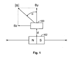
- Figure 1 shows an arrangement in which a Hall sensor 100 is fitted so as to be fixed in position in order to contactlessly detect a linear movement and detects the magnetic field of a movable permanent magnet 102.
- the magnetic field component Bz the magnetic field extending in the direction of movement
- the component By the component extending transversely thereto.
- the angle ⁇ which can be calculated in accordance with the following equation (1) is generally used as the measurement signal.
- ⁇ arctan Bz
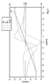
- the angle ⁇ is dependent in a comparatively linear manner on the position of the permanent magnet 102 in relation to the Hall sensor 100 up to a given threshold value.
- the characteristic line currently being measured is further linearised, as illustrated in Figure 2 by means of the line 104. That linearised line ⁇ _lin 104 then forms the characteristic output line of the sensor.
- the line 106 represents the error between the lines for a spacing of 7 mm and the line for a spacing of 6.5 mm, whilst the line 108 represents the difference between the angle ⁇ for a spacing of 6.5 mm and the angle for a spacing of 5.5 mm. That is to say, a spacing variation of 1 mm results in a deviation of 1.6% and a spacing variation of 1.5 mm results in a deviation of 2.3%.
- An object of the present invention is to improve a measurement method and a displacement sensor of the type mentioned so that as linear a measurement signal as possible is produced over as wide a measurement range as possible and is influenced as little as possible by variations in spacing between the magnetic field source and the magnetic field sensor.
- the present invention is based on the notion of not using the value for the field component in the movement direction directly in the arc tangent calculation, but instead to expand this term by a correction value. That offset value results in gradient adaptation of lines for the angle ⁇ at different spacings d.
- a displacement sensor arrangement is shown in Figure 1 .
- a Hall sensor 100 is mounted so as to be fixed in position and a permanent magnet 102 is supported so as to be linearly movable in relation to the Hall sensor 100.
- the permanent magnet 102 has such a pole configuration that its north/south axis is orientated parallel with the movement direction. In principle, however, it is also possible to use the principles of the present invention for arrangements in which the permanent magnet 102 has such a pole configuration that its north/south axis extends transversely relative to the movement direction.
- the permanent magnet 102 can be displaced out of the zero position shown in Figure 1 in two directions by, for example, approximately 25 mm.
- the Hall sensor 100 detects at least two orthogonal magnetic field components - one which extends along the movement line and one which extends transversely relative thereto. Vector addition of the two components provides the value of the magnetic field
- the angle ⁇ is defined as the angle which is enclosed by the total magnetic field vector
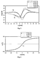
- Figure 6 shows the measurement signals which are measured in accordance with the position of the permanent magnet 102 of the magnetic field sensor, in this instance a Hall sensor 100. These are, on the one hand, the values of the magnetic field in the movement direction Bz and, on the other hand, the values of the magnetic field transverse relative to the movement direction By. Naturally, it is also possible to use the values Bx which extend orthogonally to By for the calculation.
- the arc tangent of the quotient Bz to By according to equation (1) is not used as the measurement signal but instead the magnetic field component Bz which extends in the movement direction is corrected by means of an offset value. That offset results in a gradient adaptation.
- the corrected Bz + OS line is designated 110 in Figure 6 .
- the influence of the spacing d on the measurement signal is substantially smaller in this instance. It can be seen that a variation in spacing of 1 mm results in a deviation of less than 0.3% and a variation in spacing of 1.5 mm also results in a deviation of less than 0.3%. Owing to the correction according to the invention, the spacing dependence of the output signal is reduced to approximately 1/8 with respect to the uncorrected evaluation.
- the computational establishment of that value is intended to be explained in greater detail below with reference to Figures 10 and 11 .
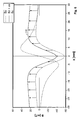
- Figure 10 the paths for the orthogonal magnetic field components By and Bz are indicated
- Figure 11 shows the line Bz in accordance with the position of the permanent magnet 102 and the derivative of the field component along the movement to the position x. It can be seen that the optimum for the term OS is achieved when the point of inflection of Bz is equal to zero, that is to say, when the second derivative is zero or the gradient of the line 112 shown is horizontal.
- offset value does not necessarily have to be added to the field component in a computational manner but instead may also be produced physically by another auxiliary magnet 114 because a constant factor is always added in the method according to the invention.
- the auxiliary magnet 114 may be arranged in a plane which has the same spacing d from the movable permanent magnet as the Hall sensor 100 (see Figures 12 and 13 ). Owing to the auxiliary magnet 114, a magnetic field component which ensures the necessary correction according to equation (2) is produced in the movement direction Bz_OS.
- auxiliary magnet 114 may also be mounted on the rear side of a circuit carrier, for example, a printed circuit board, PCB, 116, on the other side of which the Hall sensor 100 is constructed. This embodiment is schematically indicated in Figure 14 .
- the hardware solution using an auxiliary magnet 114 has the advantage that the calculation provision may be carried out in an unchanged state according to equation (1) but nevertheless the improved level of precision is achieved.
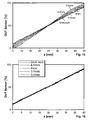
- Figure 15 shows the output signal of the sensor in accordance with the displacement of the permanent magnet for different distances d between the magnet and the sensor as a parameter.
- the different gradient values in accordance with the variation in spacing can clearly be seen. If, however, the value of the difference between the maximum of the corresponding magnetic field component and the value at the point of inflection is calculated as above with reference to Figure 11 , an offset of 14.7 mT is obtained. If the value corrected by the value 14.7 mT is used in place of the uncorrected magnetic field component for the arc tangent calculation, the group of lines of Figure 16 is produced in comparison with the group of characteristic lines of Figure 15 which are greatly dependent on spacing.
Landscapes
- Physics & Mathematics (AREA)
- General Physics & Mathematics (AREA)
- Condensed Matter Physics & Semiconductors (AREA)
- Transmission And Conversion Of Sensor Element Output (AREA)
- Measurement Of Length, Angles, Or The Like Using Electric Or Magnetic Means (AREA)
Applications Claiming Priority (2)
| Application Number | Priority Date | Filing Date | Title |
|---|---|---|---|
| DE102011115302A DE102011115302A1 (de) | 2011-09-29 | 2011-09-29 | Verfahren zum berührungslosen Messen einer relativen Position mittels eines Hallsensors |
| PCT/EP2012/068842 WO2013045430A1 (en) | 2011-09-29 | 2012-09-25 | Method for contactless measurement of a relative position by means of a hall sensor |
Publications (2)
| Publication Number | Publication Date |
|---|---|
| EP2761254A1 EP2761254A1 (en) | 2014-08-06 |
| EP2761254B1 true EP2761254B1 (en) | 2015-09-16 |
Family
ID=46982547
Family Applications (1)
| Application Number | Title | Priority Date | Filing Date |
|---|---|---|---|
| EP12769364.6A Active EP2761254B1 (en) | 2011-09-29 | 2012-09-25 | Method for contactless measurement of a relative position by means of a hall sensor |
Country Status (7)
Families Citing this family (24)
| Publication number | Priority date | Publication date | Assignee | Title |
|---|---|---|---|---|
| US9733106B2 (en) | 2013-05-24 | 2017-08-15 | Allegro Microsystems, Llc | Magnetic field sensor to detect a magnitude of a magnetic field in any direction |
| WO2014189733A1 (en) | 2013-05-24 | 2014-11-27 | Allegro Microsystems, Llc | Magnetic field sensor for detecting a magnetic field in any direction above thresholds |
| DE102013222097B4 (de) * | 2013-10-30 | 2023-03-02 | Te Connectivity Germany Gmbh | Temperatur-Kompensationsverfahren von Ansteuermagnetfeldern bei einem Hall-Sensor mit OS-Adaption |
| US10534044B2 (en) | 2013-10-30 | 2020-01-14 | Te Connectivity Germany Gmbh | Temperature compensation method of magnetic control fields in a hall sensor with OS adaption |
| JP6584424B2 (ja) | 2014-03-26 | 2019-10-02 | シェフラー テクノロジーズ アー・ゲー ウント コー. カー・ゲーSchaeffler Technologies AG & Co. KG | センサ磁石アッセンブリ |
| US11226211B2 (en) | 2014-09-08 | 2022-01-18 | Texas Instruments Incorporated | Inductive position detection |
| EP3338103B1 (en) * | 2015-08-19 | 2024-03-20 | Allegro MicroSystems, LLC | Magnetic field sensor to detect a magnitude of a magnetic field in any direction |
| CN106524887B (zh) * | 2015-09-14 | 2019-04-19 | 上海汽车集团股份有限公司 | 霍尔传感器测量位移的方法及装置 |
| US9835472B2 (en) * | 2015-09-25 | 2017-12-05 | Infineon Technologies Ag | Using cartesian coordinates for position detection with a magnetic sensor |
| JP2017067480A (ja) * | 2015-09-28 | 2017-04-06 | メレキシス テクノロジーズ エヌ ヴィ | 変位検出装置及び無段変速装置 |
| DE102016110968B4 (de) * | 2016-06-15 | 2019-05-02 | Sick Ag | Sensor |
| CN106181435A (zh) * | 2016-08-26 | 2016-12-07 | 景德镇翼腾科技有限公司 | 电动转盘及其控制方法 |
| EP3428582B1 (de) * | 2017-07-11 | 2020-03-04 | Sick Ag | Sensor |
| US10509082B2 (en) * | 2018-02-08 | 2019-12-17 | Nxp B.V. | Magnetoresistive sensor systems with stray field cancellation utilizing auxiliary sensor signals |
| CN109029228B (zh) * | 2018-05-30 | 2021-01-05 | 中南大学 | 一种用于测量轨道车辆与钢轨相对偏移的系统及方法 |
| EP4614112A2 (en) * | 2018-06-26 | 2025-09-10 | Melexis Technologies SA | Position sensor system and method, robust against disturbance fields |
| AT521356B1 (de) * | 2018-07-18 | 2020-01-15 | Avl List Gmbh | Druckdifferenzaufnehmer für ein Durchflussmessgerät sowie Durchflussmessgerät |
| JP6992771B2 (ja) * | 2019-01-29 | 2022-01-13 | Tdk株式会社 | 磁気ユニット、位置検出装置および磁気部材 |
| US11467225B2 (en) | 2019-03-08 | 2022-10-11 | Em Microelectronic-Marin Sa | Method of determining an absolute angle of a magnetic field |
| EP3705902B1 (en) * | 2019-03-08 | 2021-10-27 | EM Microelectronic-Marin SA | Method of determining an absolute angle of a magnetic field |
| DE102019205679B4 (de) | 2019-04-18 | 2022-12-15 | Infineon Technologies Ag | Linearisierung von Eingangssignalen |
| DE102019112572A1 (de) * | 2019-05-14 | 2020-11-19 | HELLA GmbH & Co. KGaA | Vorrichtung und Verfahren zur kontaktlosen Bestimmung einer Position eines Pedals |
| CN111322991B (zh) * | 2020-04-16 | 2021-07-20 | 赤峰华源新力科技有限公司 | 一种基于三维霍尔传感器测量风电塔筒倾角的系统 |
| CN113776416B (zh) * | 2021-08-27 | 2024-02-06 | 浙江沃德尔科技集团股份有限公司 | 一种抗磁场干扰的非接触式踏板位置的检测装置 |
Family Cites Families (26)
| Publication number | Priority date | Publication date | Assignee | Title |
|---|---|---|---|---|
| JPS5418768A (en) * | 1977-07-12 | 1979-02-13 | Mitsubishi Electric Corp | Angle sensor |
| US4737710A (en) * | 1983-01-27 | 1988-04-12 | Trw Inc. | Hall-effect array for sensing second spatial derivative of magnetic field |
| EP0115391A3 (en) | 1983-01-27 | 1987-06-10 | Optron, Inc. | Hall-effect position sensor apparatus |
| US5880586A (en) * | 1994-11-22 | 1999-03-09 | Robert Bosch Gmbh | Apparatus for determining rotational position of a rotatable element without contacting it |
| DE19836599A1 (de) | 1998-08-13 | 2000-02-17 | Windhorst Beteiligungsgesellsc | Verfahren zur berührungslosen magnetischen Erfassung linearer Relativbewegungen zwischen Dauermagneten und elektronischen Sensoren |
| JP2001296142A (ja) * | 2000-04-14 | 2001-10-26 | Yaskawa Electric Corp | 回転位置検出器及び回転速度検出装置 |
| EP1243897B1 (de) * | 2001-03-23 | 2013-12-18 | Melexis Technologies NV | Magnetischer Weggeber |
| JP2002372402A (ja) * | 2001-06-13 | 2002-12-26 | Alps Electric Co Ltd | シートポジションセンサ |
| JP2003075108A (ja) * | 2001-09-04 | 2003-03-12 | Asahi Kasei Corp | 回転角度センサ |
| JP2003167627A (ja) * | 2001-12-04 | 2003-06-13 | Sanetec:Kk | 位置検出センサ |
| JP2003240598A (ja) * | 2002-02-13 | 2003-08-27 | Asahi Kasei Corp | デジタル角度測定システム |
| DE102004002649A1 (de) * | 2004-01-17 | 2005-08-11 | Ssg Semiconductor Systems Gmbh | Positionstolerante Weg- und Winkelmessung |
| US7112962B2 (en) * | 2004-11-18 | 2006-09-26 | Honeywell International Inc. | Angular position detection utilizing a plurality of rotary configured magnetic sensors |
| US20080134727A1 (en) * | 2005-02-01 | 2008-06-12 | Lutz May | Position Sensor and Washing Machine |
| CA2641407C (en) | 2006-02-03 | 2013-12-17 | California Linear Devices, Inc. | Encoder signal analysis system for high-resolution position measurement |
| JP4756475B2 (ja) * | 2006-10-20 | 2011-08-24 | 株式会社デンソー | 磁気ロータ及び回転角度検出装置 |
| FR2909170B1 (fr) * | 2006-11-28 | 2010-01-29 | Moving Magnet Tech Mmt | Capteur de position linaire ou rotatif a profil d'aimant variable preferentiellement de maniere quasi sinusoidal. |
| DE102006061927A1 (de) * | 2006-12-21 | 2008-06-26 | Siemens Ag | Verfahren und Einrichtung zum Messen des Pollagewinkels eines Magnetschwebefahrzeugs einer Magnetschwebebahn |
| JP2009002737A (ja) * | 2007-06-20 | 2009-01-08 | Denso Corp | 回転角度検出装置 |
| DE102007060707B4 (de) * | 2007-12-17 | 2017-12-07 | Austriamicrosystems Ag | Anordnung zur Detektion einer Bewegung eines Körpers sowie Verfahren zum Betrieb einer solchen Anordnung |
| CN101216324B (zh) * | 2008-01-18 | 2011-07-06 | 浙江飞亚电子有限公司 | 一种角位移传感器 |
| JP4900837B2 (ja) * | 2008-05-16 | 2012-03-21 | 日立金属株式会社 | 回転角度検出装置および回転機 |
| DE102008045177A1 (de) | 2008-08-30 | 2010-03-04 | Festo Ag & Co. Kg | Messverfahren zur berührungslosen Erfassung linearer Relativbewegungen zwischen einer Sensoranordnung und einem Permanentmagneten |
| JP5216030B2 (ja) * | 2010-01-28 | 2013-06-19 | 東京コスモス電機株式会社 | 多方向入力装置 |
| DE102010011723B4 (de) * | 2010-03-17 | 2012-06-06 | Austriamicrosystems Ag | Sensoranordnung und Verfahren zum Betreiben einer Sensoranordnung |
| DE102012205903B4 (de) * | 2012-04-11 | 2014-01-30 | Tyco Electronics Amp Gmbh | Verfahren zum berührungslosen messen einer relativen position mittels eines magnetfeldsensorarrays auf halleffektbasis und weggeber |
-
2011
- 2011-09-29 DE DE102011115302A patent/DE102011115302A1/de not_active Ceased
-
2012
- 2012-09-25 WO PCT/EP2012/068842 patent/WO2013045430A1/en active Application Filing
- 2012-09-25 BR BR112014007387A patent/BR112014007387A2/pt active Search and Examination
- 2012-09-25 US US14/348,029 patent/US9360537B2/en active Active
- 2012-09-25 CN CN201280047390.7A patent/CN103988052B/zh active Active
- 2012-09-25 EP EP12769364.6A patent/EP2761254B1/en active Active
- 2012-09-25 JP JP2014532346A patent/JP6210642B2/ja active Active
Also Published As
| Publication number | Publication date |
|---|---|
| US9360537B2 (en) | 2016-06-07 |
| CN103988052B (zh) | 2017-03-01 |
| WO2013045430A1 (en) | 2013-04-04 |
| EP2761254A1 (en) | 2014-08-06 |
| US20140239942A1 (en) | 2014-08-28 |
| DE102011115302A1 (de) | 2013-04-04 |
| JP6210642B2 (ja) | 2017-10-11 |
| CN103988052A (zh) | 2014-08-13 |
| BR112014007387A2 (pt) | 2017-04-04 |
| JP2014528085A (ja) | 2014-10-23 |
Similar Documents
| Publication | Publication Date | Title |
|---|---|---|
| EP2761254B1 (en) | Method for contactless measurement of a relative position by means of a hall sensor | |
| EP2836799B1 (en) | Displacement sensor for contactlessly measuring a position by means of a plurality of magnetic field sensors arranged in series | |
| CN104220844B (zh) | 借助磁场传感器阵列基于霍耳效应非接触测量相对位置的位移传感器 | |
| EP3469383B1 (en) | Magnetic field sensor having error correction | |
| EP2820384B1 (en) | Method for contactlessly measuring a relative position by means of a 3d hall sensor having measurement signal store | |
| CN105705959B (zh) | 在具有偏移斜率适应的霍尔传感器中磁控制场的温度补偿方法 | |
| US20090243598A1 (en) | Position measurement using magnetic fields | |
| US20090243402A1 (en) | Position measurement using magnetic fields | |
| US10534044B2 (en) | Temperature compensation method of magnetic control fields in a hall sensor with OS adaption | |
| US10989566B2 (en) | Magnetic sensor system for measuring linear position | |
| WO2008107300A2 (en) | Sensor arrangement and measuring method | |
| CN114391090B (zh) | 带有霍尔传感器和磁体的位移测量装置 | |
| US20230258684A1 (en) | Omnidirectional rotational speed and rotational direction sensor | |
| CN119492321A (zh) | 用于补偿角度误差的方法 | |
| JP2010008064A (ja) | 位置決め装置 |
Legal Events
| Date | Code | Title | Description |
|---|---|---|---|
| PUAI | Public reference made under article 153(3) epc to a published international application that has entered the european phase |
Free format text: ORIGINAL CODE: 0009012 |
|
| 17P | Request for examination filed |
Effective date: 20140318 |
|
| AK | Designated contracting states |
Kind code of ref document: A1 Designated state(s): AL AT BE BG CH CY CZ DE DK EE ES FI FR GB GR HR HU IE IS IT LI LT LU LV MC MK MT NL NO PL PT RO RS SE SI SK SM TR |
|
| DAX | Request for extension of the european patent (deleted) | ||
| REG | Reference to a national code |
Ref country code: DE Ref legal event code: R079 Ref document number: 602012010756 Country of ref document: DE Free format text: PREVIOUS MAIN CLASS: G01D0005140000 Ipc: G01R0033070000 |
|
| GRAP | Despatch of communication of intention to grant a patent |
Free format text: ORIGINAL CODE: EPIDOSNIGR1 |
|
| RIC1 | Information provided on ipc code assigned before grant |
Ipc: G01D 5/14 20060101ALI20150319BHEP Ipc: G01R 33/07 20060101AFI20150319BHEP Ipc: G01D 5/244 20060101ALI20150319BHEP Ipc: G01B 7/14 20060101ALI20150319BHEP |
|
| INTG | Intention to grant announced |
Effective date: 20150331 |
|
| GRAS | Grant fee paid |
Free format text: ORIGINAL CODE: EPIDOSNIGR3 |
|
| GRAA | (expected) grant |
Free format text: ORIGINAL CODE: 0009210 |
|
| RAP1 | Party data changed (applicant data changed or rights of an application transferred) |
Owner name: TE CONNECTIVITY GERMANY GMBH |
|
| AK | Designated contracting states |
Kind code of ref document: B1 Designated state(s): AL AT BE BG CH CY CZ DE DK EE ES FI FR GB GR HR HU IE IS IT LI LT LU LV MC MK MT NL NO PL PT RO RS SE SI SK SM TR |
|
| REG | Reference to a national code |
Ref country code: GB Ref legal event code: FG4D |
|
| REG | Reference to a national code |
Ref country code: CH Ref legal event code: EP |
|
| REG | Reference to a national code |
Ref country code: IE Ref legal event code: FG4D |
|
| REG | Reference to a national code |
Ref country code: AT Ref legal event code: REF Ref document number: 750208 Country of ref document: AT Kind code of ref document: T Effective date: 20151015 |
|
| REG | Reference to a national code |
Ref country code: DE Ref legal event code: R096 Ref document number: 602012010756 Country of ref document: DE |
|
| REG | Reference to a national code |
Ref country code: NL Ref legal event code: MP Effective date: 20150916 |
|
| PG25 | Lapsed in a contracting state [announced via postgrant information from national office to epo] |
Ref country code: LT Free format text: LAPSE BECAUSE OF FAILURE TO SUBMIT A TRANSLATION OF THE DESCRIPTION OR TO PAY THE FEE WITHIN THE PRESCRIBED TIME-LIMIT Effective date: 20150916 Ref country code: FI Free format text: LAPSE BECAUSE OF FAILURE TO SUBMIT A TRANSLATION OF THE DESCRIPTION OR TO PAY THE FEE WITHIN THE PRESCRIBED TIME-LIMIT Effective date: 20150916 Ref country code: NO Free format text: LAPSE BECAUSE OF FAILURE TO SUBMIT A TRANSLATION OF THE DESCRIPTION OR TO PAY THE FEE WITHIN THE PRESCRIBED TIME-LIMIT Effective date: 20151216 Ref country code: GR Free format text: LAPSE BECAUSE OF FAILURE TO SUBMIT A TRANSLATION OF THE DESCRIPTION OR TO PAY THE FEE WITHIN THE PRESCRIBED TIME-LIMIT Effective date: 20151217 Ref country code: LV Free format text: LAPSE BECAUSE OF FAILURE TO SUBMIT A TRANSLATION OF THE DESCRIPTION OR TO PAY THE FEE WITHIN THE PRESCRIBED TIME-LIMIT Effective date: 20150916 |
|
| REG | Reference to a national code |
Ref country code: LT Ref legal event code: MG4D |
|
| REG | Reference to a national code |
Ref country code: AT Ref legal event code: MK05 Ref document number: 750208 Country of ref document: AT Kind code of ref document: T Effective date: 20150916 |
|
| PG25 | Lapsed in a contracting state [announced via postgrant information from national office to epo] |
Ref country code: SE Free format text: LAPSE BECAUSE OF FAILURE TO SUBMIT A TRANSLATION OF THE DESCRIPTION OR TO PAY THE FEE WITHIN THE PRESCRIBED TIME-LIMIT Effective date: 20150916 Ref country code: RS Free format text: LAPSE BECAUSE OF FAILURE TO SUBMIT A TRANSLATION OF THE DESCRIPTION OR TO PAY THE FEE WITHIN THE PRESCRIBED TIME-LIMIT Effective date: 20150916 Ref country code: HR Free format text: LAPSE BECAUSE OF FAILURE TO SUBMIT A TRANSLATION OF THE DESCRIPTION OR TO PAY THE FEE WITHIN THE PRESCRIBED TIME-LIMIT Effective date: 20150916 |
|
| PG25 | Lapsed in a contracting state [announced via postgrant information from national office to epo] |
Ref country code: NL Free format text: LAPSE BECAUSE OF FAILURE TO SUBMIT A TRANSLATION OF THE DESCRIPTION OR TO PAY THE FEE WITHIN THE PRESCRIBED TIME-LIMIT Effective date: 20150916 |
|
| PG25 | Lapsed in a contracting state [announced via postgrant information from national office to epo] |
Ref country code: EE Free format text: LAPSE BECAUSE OF FAILURE TO SUBMIT A TRANSLATION OF THE DESCRIPTION OR TO PAY THE FEE WITHIN THE PRESCRIBED TIME-LIMIT Effective date: 20150916 Ref country code: CZ Free format text: LAPSE BECAUSE OF FAILURE TO SUBMIT A TRANSLATION OF THE DESCRIPTION OR TO PAY THE FEE WITHIN THE PRESCRIBED TIME-LIMIT Effective date: 20150916 Ref country code: SK Free format text: LAPSE BECAUSE OF FAILURE TO SUBMIT A TRANSLATION OF THE DESCRIPTION OR TO PAY THE FEE WITHIN THE PRESCRIBED TIME-LIMIT Effective date: 20150916 Ref country code: IT Free format text: LAPSE BECAUSE OF FAILURE TO SUBMIT A TRANSLATION OF THE DESCRIPTION OR TO PAY THE FEE WITHIN THE PRESCRIBED TIME-LIMIT Effective date: 20150916 Ref country code: ES Free format text: LAPSE BECAUSE OF FAILURE TO SUBMIT A TRANSLATION OF THE DESCRIPTION OR TO PAY THE FEE WITHIN THE PRESCRIBED TIME-LIMIT Effective date: 20150916 Ref country code: IS Free format text: LAPSE BECAUSE OF FAILURE TO SUBMIT A TRANSLATION OF THE DESCRIPTION OR TO PAY THE FEE WITHIN THE PRESCRIBED TIME-LIMIT Effective date: 20160116 |
|
| REG | Reference to a national code |
Ref country code: CH Ref legal event code: PL |
|
| PG25 | Lapsed in a contracting state [announced via postgrant information from national office to epo] |
Ref country code: PL Free format text: LAPSE BECAUSE OF FAILURE TO SUBMIT A TRANSLATION OF THE DESCRIPTION OR TO PAY THE FEE WITHIN THE PRESCRIBED TIME-LIMIT Effective date: 20150916 Ref country code: RO Free format text: LAPSE BECAUSE OF FAILURE TO SUBMIT A TRANSLATION OF THE DESCRIPTION OR TO PAY THE FEE WITHIN THE PRESCRIBED TIME-LIMIT Effective date: 20150916 Ref country code: PT Free format text: LAPSE BECAUSE OF FAILURE TO SUBMIT A TRANSLATION OF THE DESCRIPTION OR TO PAY THE FEE WITHIN THE PRESCRIBED TIME-LIMIT Effective date: 20160118 Ref country code: AT Free format text: LAPSE BECAUSE OF FAILURE TO SUBMIT A TRANSLATION OF THE DESCRIPTION OR TO PAY THE FEE WITHIN THE PRESCRIBED TIME-LIMIT Effective date: 20150916 |
|
| REG | Reference to a national code |
Ref country code: DE Ref legal event code: R097 Ref document number: 602012010756 Country of ref document: DE |
|
| REG | Reference to a national code |
Ref country code: IE Ref legal event code: MM4A |
|
| PG25 | Lapsed in a contracting state [announced via postgrant information from national office to epo] |
Ref country code: MC Free format text: LAPSE BECAUSE OF FAILURE TO SUBMIT A TRANSLATION OF THE DESCRIPTION OR TO PAY THE FEE WITHIN THE PRESCRIBED TIME-LIMIT Effective date: 20150916 |
|
| PLBE | No opposition filed within time limit |
Free format text: ORIGINAL CODE: 0009261 |
|
| STAA | Information on the status of an ep patent application or granted ep patent |
Free format text: STATUS: NO OPPOSITION FILED WITHIN TIME LIMIT |
|
| PG25 | Lapsed in a contracting state [announced via postgrant information from national office to epo] |
Ref country code: LI Free format text: LAPSE BECAUSE OF NON-PAYMENT OF DUE FEES Effective date: 20150930 Ref country code: CH Free format text: LAPSE BECAUSE OF NON-PAYMENT OF DUE FEES Effective date: 20150930 Ref country code: IE Free format text: LAPSE BECAUSE OF NON-PAYMENT OF DUE FEES Effective date: 20150925 |
|
| 26N | No opposition filed |
Effective date: 20160617 |
|
| PG25 | Lapsed in a contracting state [announced via postgrant information from national office to epo] |
Ref country code: DK Free format text: LAPSE BECAUSE OF FAILURE TO SUBMIT A TRANSLATION OF THE DESCRIPTION OR TO PAY THE FEE WITHIN THE PRESCRIBED TIME-LIMIT Effective date: 20150916 |
|
| REG | Reference to a national code |
Ref country code: FR Ref legal event code: PLFP Year of fee payment: 5 |
|
| PG25 | Lapsed in a contracting state [announced via postgrant information from national office to epo] |
Ref country code: SI Free format text: LAPSE BECAUSE OF FAILURE TO SUBMIT A TRANSLATION OF THE DESCRIPTION OR TO PAY THE FEE WITHIN THE PRESCRIBED TIME-LIMIT Effective date: 20150916 |
|
| PG25 | Lapsed in a contracting state [announced via postgrant information from national office to epo] |
Ref country code: MT Free format text: LAPSE BECAUSE OF FAILURE TO SUBMIT A TRANSLATION OF THE DESCRIPTION OR TO PAY THE FEE WITHIN THE PRESCRIBED TIME-LIMIT Effective date: 20150916 |
|
| GBPC | Gb: european patent ceased through non-payment of renewal fee |
Effective date: 20160925 |
|
| PG25 | Lapsed in a contracting state [announced via postgrant information from national office to epo] |
Ref country code: SM Free format text: LAPSE BECAUSE OF FAILURE TO SUBMIT A TRANSLATION OF THE DESCRIPTION OR TO PAY THE FEE WITHIN THE PRESCRIBED TIME-LIMIT Effective date: 20150916 Ref country code: BG Free format text: LAPSE BECAUSE OF FAILURE TO SUBMIT A TRANSLATION OF THE DESCRIPTION OR TO PAY THE FEE WITHIN THE PRESCRIBED TIME-LIMIT Effective date: 20150916 Ref country code: HU Free format text: LAPSE BECAUSE OF FAILURE TO SUBMIT A TRANSLATION OF THE DESCRIPTION OR TO PAY THE FEE WITHIN THE PRESCRIBED TIME-LIMIT; INVALID AB INITIO Effective date: 20120925 |
|
| PG25 | Lapsed in a contracting state [announced via postgrant information from national office to epo] |
Ref country code: CY Free format text: LAPSE BECAUSE OF FAILURE TO SUBMIT A TRANSLATION OF THE DESCRIPTION OR TO PAY THE FEE WITHIN THE PRESCRIBED TIME-LIMIT Effective date: 20150916 |
|
| PG25 | Lapsed in a contracting state [announced via postgrant information from national office to epo] |
Ref country code: BE Free format text: LAPSE BECAUSE OF NON-PAYMENT OF DUE FEES Effective date: 20150930 Ref country code: GB Free format text: LAPSE BECAUSE OF NON-PAYMENT OF DUE FEES Effective date: 20160925 |
|
| REG | Reference to a national code |
Ref country code: FR Ref legal event code: PLFP Year of fee payment: 6 |
|
| PG25 | Lapsed in a contracting state [announced via postgrant information from national office to epo] |
Ref country code: LU Free format text: LAPSE BECAUSE OF NON-PAYMENT OF DUE FEES Effective date: 20150925 |
|
| PG25 | Lapsed in a contracting state [announced via postgrant information from national office to epo] |
Ref country code: MK Free format text: LAPSE BECAUSE OF FAILURE TO SUBMIT A TRANSLATION OF THE DESCRIPTION OR TO PAY THE FEE WITHIN THE PRESCRIBED TIME-LIMIT Effective date: 20150916 Ref country code: TR Free format text: LAPSE BECAUSE OF FAILURE TO SUBMIT A TRANSLATION OF THE DESCRIPTION OR TO PAY THE FEE WITHIN THE PRESCRIBED TIME-LIMIT Effective date: 20150916 |
|
| REG | Reference to a national code |
Ref country code: FR Ref legal event code: PLFP Year of fee payment: 7 |
|
| PG25 | Lapsed in a contracting state [announced via postgrant information from national office to epo] |
Ref country code: AL Free format text: LAPSE BECAUSE OF FAILURE TO SUBMIT A TRANSLATION OF THE DESCRIPTION OR TO PAY THE FEE WITHIN THE PRESCRIBED TIME-LIMIT Effective date: 20150916 |
|
| PGFP | Annual fee paid to national office [announced via postgrant information from national office to epo] |
Ref country code: DE Payment date: 20240702 Year of fee payment: 13 |
|
| PGFP | Annual fee paid to national office [announced via postgrant information from national office to epo] |
Ref country code: FR Payment date: 20240702 Year of fee payment: 13 |