EP2760251B1 - Induction heating cooker - Google Patents
Induction heating cooker Download PDFInfo
- Publication number
- EP2760251B1 EP2760251B1 EP12834381.1A EP12834381A EP2760251B1 EP 2760251 B1 EP2760251 B1 EP 2760251B1 EP 12834381 A EP12834381 A EP 12834381A EP 2760251 B1 EP2760251 B1 EP 2760251B1
- Authority
- EP
- European Patent Office
- Prior art keywords
- heating
- load
- detecting means
- power
- circuits
- Prior art date
- Legal status (The legal status is an assumption and is not a legal conclusion. Google has not performed a legal analysis and makes no representation as to the accuracy of the status listed.)
- Not-in-force
Links
Images


Classifications
-
- H—ELECTRICITY
- H05—ELECTRIC TECHNIQUES NOT OTHERWISE PROVIDED FOR
- H05B—ELECTRIC HEATING; ELECTRIC LIGHT SOURCES NOT OTHERWISE PROVIDED FOR; CIRCUIT ARRANGEMENTS FOR ELECTRIC LIGHT SOURCES, IN GENERAL
- H05B6/00—Heating by electric, magnetic or electromagnetic fields
- H05B6/02—Induction heating
- H05B6/06—Control, e.g. of temperature, of power
- H05B6/062—Control, e.g. of temperature, of power for cooking plates or the like
-
- H—ELECTRICITY
- H05—ELECTRIC TECHNIQUES NOT OTHERWISE PROVIDED FOR
- H05B—ELECTRIC HEATING; ELECTRIC LIGHT SOURCES NOT OTHERWISE PROVIDED FOR; CIRCUIT ARRANGEMENTS FOR ELECTRIC LIGHT SOURCES, IN GENERAL
- H05B2213/00—Aspects relating both to resistive heating and to induction heating, covered by H05B3/00 and H05B6/00
- H05B2213/05—Heating plates with pan detection means
Definitions
- the present invention relates to an induction heating cooker including a plurality of heating coils that are arranged for a single heating port.
- an induction heating cooker has been known that includes a top plate on which a subject to be heated is placed, a plurality of heating coils that are arranged below the top plate so as to be close to one another, a circuit that supplies high-frequency power to each of the heating coils, and load detecting means for detecting, for each of the heating coils, that a subject to be heated is placed thereon (see, for example, Patent Literature 1).
- Document FR 2 863 039 A1 discloses a method for heating a container placed on a cooktop including heating elements which are associated respectively with inductors which form elements for detecting the presence of the container and are distributed along a frame which is embodied such that it is two-dimensional in a cooking area.
- the method includes searching a heating area consisting of the heating elements arrangement which are at least partially covered by the container and computing a power supplied by each heating element of the heating area according to a total specified power associated thereto and the degree of coverage of each detection element associated to heating element by the container.
- Document EP 0 716 560 A1 discloses a device for induction heating of cooking receptacles, of the type comprising at least two concentric induction coils supplied by a generator. Each induction coil is supplied by a separate generator, the number of induction coils being equal to the number of supply generators.
- a control block effects the independent operation of each supply generator. The control block is adapted to cause to operate according to a sequential order the supply generators during a detection step of the presence of a load on the corresponding induction coil, starting with the generator corresponding to the innermost concentric induction coil and progressing to the outermost concentric induction coil covered by the receptacle to be heated.
- the supply generators are identical to each other and have the same nominal power, for the modular replacement of one supply generator by another supply generator of the same characteristics.
- a cooking appliance comprises a top plate on which a cooking container is placed, a plurality of winding parts including a plurality of coils horizontally arranged under the top plate, a plurality of relay parts including a plurality of relays that each connected to the plurality of coils, and an inverter part for applying a voltage of high frequency to the plurality of winding parts.
- Patent Literature 1 Japanese Unexamined Patent Application Publication No. 2008-293871 (Claim 2)
- the presence or absence of load is determined for each heating coil, and the circuit supplies high-frequency current only to a heating coil above which the presence of a subject to be heated is detected by the load detecting means.
- the heating efficiency in the case of heating a small pan can be improved, and temperature irregularity in the case of heating a large pan can be suppressed.
- the present invention achieves, in an induction heating cooker including a plurality of heating coils that are arranged for a single heating port, an improved heating distribution in the case where a specific heating mode is selected.
- An induction heating cooker includes a top plate on which a cooking container serving as a subject to be heated is placed; a plurality of heating coils that are arranged below the top plate so as to be close to one another for a single heating port; a plurality of inverter circuits each of which supplies high-frequency power to one of a plurality of load circuits that includes a corresponding one of the heating coils; power detecting means for detecting power output from each of the inverter circuits to a corresponding one of the load circuits or power input to a corresponding one of the inverter circuits; output current detecting means for detecting an output current of each of the inverter circuits; load detecting means for performing load detection on a basis of results of detection by the power detecting means and the output current detecting means; control means for performing driving control for the plurality of inverter circuits on a basis of results of detection by the power detecting means, the output current detecting means, and the load detecting means; and operation means for inputting, to
- the load detecting means performs the load detection by separately and individually allowing the load circuits to enter individual conduction states.
- the control means performs the load detection every time heating power setting is changed, and has a heating mode in which power distribution is set for each of the heating coils or each of the inverter circuits on the basis of the result of load detection.
- control means performs control such that every time heating power setting is changed, load detecting means performs load detection by allowing separately and individually allowing the heating coils or inverter circuits to be in individual conduction states, and the control means sets power distribution for each heating coil or each inverter circuit on the basis of a result of load detection.
- load detection is not performed in the state in which high-frequency currents are flowed to a plurality of heating coils that are arranged close to one another at the same time.
- Detection of load to be heated can be performed while suppressing the influence of magnetic coupling between the heating coils, and power distribution to the heating coils is performed on the basis of the result of detection.
- a subject to be heated can be heated at a desired heating distribution without being affected by magnetic coupling between heating coils.
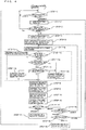
- Fig. 1 is a diagram illustrating the configuration of an induction heating cooker according to Embodiment 1.
- numeral 101 denotes a top plate
- 102 denotes a main unit casing
- 103 denotes a circuit that supplies high-frequency current
- 104 denotes an operation unit
- 105 denotes display means
- 16 denotes heating coils.
- the top plate 101 is provided so that a subject to be heated, such as a pan, is placed above the top plate 101, and includes heating ports 106 each representing the location at which a pan is to be placed.
- the circuit 103, the display means 105, and the heating coils 16 are accommodated inside the main unit casing 102.
- the upper surface of the main unit casing 102 is covered with the top plate 101, and the inner structure of the main unit casing 102 is accommodated in the main unit casing 102.
- the circuit 103 has the configuration explained later with reference to Fig. 2 , and supplies high-frequency current to the heating coils 16.
- the operation unit 104 is provided so that a user adjusts heating output, and the user can select among a plurality of heating modes.
- the user can select among heating modes, such as a uniform heating mode in which pancakes or the like are baked, a water-boiling mode in which heating efficiency has priority over heating distribution, and the like.
- high heating efficiency means that the load resistance of a heating coil is large and a large heating output can be obtained by a small coil current.
- the display means 105 is a screen display device including a liquid crystal display device or the like, and displays the operation state of the induction heating cooker.
- the plurality of heating coils 16 are arranged close to one another in association with corresponding heating ports 106. In this embodiment, five heating coils 16 are arranged for each of the heating ports 106.
- Fig. 2 is a diagram illustrating the circuit configuration of a heating port of the induction heating cooker according to Embodiment 1.
- the induction heating cooker is connected to an alternating-current power supply 1. Electric power supplied from the alternating-current power supply 1 is converted by a direct-current power supply circuit 2 into direct-current power.
- the direct-current power supply circuit 2 includes a rectifying diode bridge 3 that rectifies alternating-current power, and reactors 4a to 4e and smoothing capacitors 5a to 5e that are provided in association with respective inverter circuits 6a to 6e. As described later, the direct-current power supply circuit 2 supplies direct-current power to the plurality of inverter circuits 6a to 6e, which are provided in association with the number of load circuits 15a to 15e including respective heating coils 16a to 16e.
- the inverter circuits 6a to 6e have the same configuration.
- the inverter circuits 6a to 6e include switching elements (upper switches) 7a to 7e and switching elements (lower switches) 8a to 8e that are connected in series between direct-current buses of the direct-current power supply circuit 2, and diodes 9a to 9e and 10a to 10e that are connected in antiparallel to the switching elements.
- the series of two switching elements are alternately turned on and off at high frequency by driving circuits 11a to 11 e, and high-frequency voltage is generated between an output terminal and one end of the direct-current bus.
- output voltage detecting means 13a to 13e High-frequency voltages output from the inverter circuits 6a to 6e are detected by output voltage detecting means 13a to 13e, and output currents of the inverter circuits are also flowed to the heating coils and are detected by output current detecting means 12a to 12e.
- reference numerals 14a to 14e denote output power detecting means for generating output power values of the inverter circuits by integrating the output voltage values and the output current values (heating coil current values) detected by the output voltage detecting means 13a to 13e and the output current detecting means 12a to 12e.
- Load circuits 15a to 15e are connected between output terminals of the inverter circuits 6a to 6e and a lower-potential-side bus of the direct-current power supply.
- the load circuits 15a to 15e include series circuits of the heating coils 16a to 16e and resonant capacitors 17a to 17e, and clamp diodes 18a to 18e that are connected in parallel to the resonant capacitors 17a to 17e.
- the clamp diodes 18a to 18e clamp potentials of connection points of the heating coils 16a to 16e and the resonant capacitors 17a to 17e to the potential of the lower-potential-side bus of the direct-current power supply. Due to the operation of the clamp diodes 18a to 18e, currents flowing in the heating coils 16a to 16e do not commutate in the state in which the lower switches 8a to 8e are connected.
- Control means 19 performs driving control for each of the inverter circuits 6a to 6e.
- the control means 19 controls the driving circuits 11a to 11e, on the basis of output currents and output power of the inverter circuits 6a to 6e.
- load resistance detecting means 20 that is provided inside the control means 19 detects load resistances R of the load circuits 15a to 15e, on the basis of the power detected by the output power detecting means 14a to 14e and the currents detected by the output current detecting means 12a to 12e.
- the load resistance detecting means 20 constitutes load detecting means.
- the load resistances R increase or decrease in accordance with loss (heat generation) based on induced eddy currents generated when magnetic fluxes generated by high-frequency currents flowing in the heating coils 15a to 15e are interlinked with the bottom of a pan placed above the heating coils.
- the load resistance R increases as the size of the bottom of a pan facing a corresponding heating coil increases.
- the presence or absence and the size of a pan (load) placed above a corresponding heating coil can be determined on the basis of the value of the load resistance R.
- a threshold R1 is set.
- the threshold R1 varies according to the number of windings of a copper wire of a heating coil, the threshold R1 is set to, for example, about several ⁇ (2 ⁇ to 5 ⁇ ).
- Fig. 3 illustrates an example of the arrangement of heating coils of the induction heating cooker according to Embodiment 1.
- (a) is a side view illustrating the arrangement of heating coils
- (b) is a plan view illustrating the arrangement of the heating coils.
- the five heating coils 16a to 16e are arranged close to one another for a single heating port of the induction heating cooker according to this embodiment, and a pan 22, which is a cooking container serving as a subject to be heated, is placed above the heating coils 16a to 16e via the top plate 101.
- Fig. 4 is a flowchart illustrating a heating control process by the control means 19 of the induction heating cooker according to this embodiment.
- Fig. 5 is a flowchart illustrating a load detecting process performed by the load detecting means, which detects the presence or absence and the size of a pan (load) above each heating coil.
- Fig. 6 is a flowchart illustrating a target power distribution process for performing allocation of heating power to be output from heating coils.
- the operation performed by the control means of the induction heating cooker according to Embodiment 1 will be explained with reference to the flowcharts.
- the control means 19 determines whether or not an instruction of a heating request for heating power setting or the like has been input from the operation unit 104 (step 1). In the case where a heating request has been input, in order to determine whether a pan to be heated is placed above the heating coils 16a to 16e, the control means 19 performs a load detecting process (step 2).
- the driving circuit 11a is first controlled such that the inverter circuit 6a for the heating coil 16a is driven, and a predetermined high-frequency voltage is applied to the load circuit 15a including the heating coil 16a (step 2-1-1). At this time, control is performed such that high-frequency voltage is not applied to the load circuits 15b to 15e including the other heating coils 16b and 16e. Then, the high-frequency current of the heating coil 16a and the high-frequency power output from the inverter circuit 6a are detected by the output current detecting means 12a and the output power detecting means 14a (step 2-1-2).
- the inverter circuit load detecting processing is performed (steps 2-2 to 2-5). Also at this time, control is performed for each heating coil such that high-frequency voltage is applied only to a load circuit including the heating coil, and high-frequency voltage is not applied to load circuits including the other heating coils.
- step 3 After the load detecting process (step 2) is terminated, it is determined whether or not a heating coil above which appropriate load is placed exists (step 3). In the case where no heating coil above which appropriate load is placed exists, the process returns to step 1. In the case where a heating coil above which appropriate load is placed exists, a target power distribution process for each of the heating coils 16a to 16e is performed (step 4).
- the target power distribution process is performed such that the entire heating power output Wall set by the operation unit 104 is distributed for target power for the heating coils 16a to 16e, on the basis of load resistance data for the corresponding heating coils.
- steps 4-2 to 4-5 processing for setting target power is performed (steps 4-2 to 4-5).
- heating densities [(output of a heating coil / area of a portion of the heating coil that faces a pan)] of the heating coils are the same.
- step 4 after setting of the target power for each of the heating coils (step 4) is completed, a driving circuit for an inverter circuit for a heating coil above which the presence of appropriate load is determined is controlled, and inverter output is started (step 5).
- the output current detecting means 12a to 12e and the output power detecting means 14a to 14e detect output currents and power of the inverter circuits 6a to 6e (step 6). Then, output control processing for the inverter circuits 6a to 6e is performed for each of the heating coils 16a to 16e.
- step 7 In the output control processing for the heating coil 16a (step 7), first, it is determined whether the inverter circuit 6a is being driven (step 7-1). In the case where the inverter circuit 6a is not being driven, the processing is terminated. In the case where the inverter circuit 6a is being driven, it is determined whether or not output current of the inverter circuit 6a flowing in the heating coil 16a is excessive (step 7-2). In the case where the output current of the inverter circuit 6a is not excessive, the target power Wa for the heating coil 16a is compared with the detected power W (step 7-3). As a result, in the case where the detected power of the heating coil 16a is smaller than the target power, control for increasing the inverter circuit output is performed (step 7-4).
- step 7-5 In the case where the detected power is substantially equal to the target power, the inverter circuit output is maintained. In the case where it is determined in step 7-2 that the current of the heating coil 16a is excessive or in the case where it is determined in step 7-3 that the detected power W is greater than the target power Wa, control for decreasing the inverter circuit output is performed (step 7-5).
- the inverter circuits 6b to 6e are controlled (steps 8 to 11).
- step 12 it is determined whether or not a heating stop request has been received from the operation unit 104 (step 12).
- the driving circuits 11a to 11e are controlled such that driving of all the inverter circuits 6a to 6e is stopped (step 13). Then, the process returns to step 1.
- step 14 it is determined whether or not a set heating power changing request has been received. In the case where a heating power changing request has not been received, the process returns to step 6. In contrast, in the case where a heating power changing request has been received, it is determined which heating mode has been selected by the operation unit 104 (step 15).
- the selected heating mode is a heating mode in which priority is given to heating distribution control (for example, a uniform heating mode (a mode in which the entire bottom of a pan having a large diameter is heated uniformly, a heating mode in which the periphery of a pan is given priority to increase the heating density of outer heating coils so that heating of the periphery of the pan can be increased), or the like)
- the driving circuits 11a to 11e are controlled such that driving of all the inverter circuits 6a to 6e is stopped (step 16).
- the process returns to the load detecting means of step 2, in which the load detecting process is performed for each heating coil, and the load resistances Ra to Re regarding the size of a subject to be heated (pan) above the corresponding heating coils are detected.
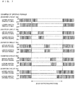
- An example of driving signals for the inverter circuits at this time is illustrated in Fig. 7 .
- step 15 In the case where the heating mode selected in step 15 is a heating mode in which heating efficiency or operability has priority over heating distribution, the process returns to step 4, in which distribution of heating power is performed on the basis of the load resistances of the heating coils detected at the time of starting heating.
- the induction heating cooker in which a plurality of heating coils are arranged adjacent to one another for a single heating port and high-frequency current is flowed only to a heating coil above which a subject to be heated (pan) is placed, has a predetermined heating mode, such as a uniform heating mode, in which load detecting means for each heating coil is performed by stopping concurrent conduction to the plurality of heating coils every time set heating power is changed.
- a predetermined heating mode such as a uniform heating mode, in which load detecting means for each heating coil is performed by stopping concurrent conduction to the plurality of heating coils every time set heating power is changed.
- Fig. 8 is a flowchart illustrating a load detecting process performed by load detecting means in control means of an induction heating cooker according to Embodiment 2
- Fig. 9 illustrates an example of driving signals of the induction heating cooker according to Embodiment 2.
- the load detecting process performed by the load detecting means in the control means of the induction heating cooker according to Embodiment 1 in order to avoid the influence of magnetic coupling between heating coils that are arranged adjacent to one another, by sequentially causing high-frequency current to be flowed to each load circuit including a heating coil, a subject to be heated (pan) placed above the heating coil is detected.
- Embodiment 2 at the time of the load detecting process, by concurrently allowing a pair of load circuits including heating coils that are not adjacent to each other to achieve conduction of high-frequency current, a reduction in the load detection time can be achieved.
- the circuit configuration, the arrangement of heating coils, and a heating control process by the control means 19 in the induction heating cooker according to Embodiment 2 are illustrated in Fig. 2 , Fig. 3 , and the flowchart of Fig. 4 , respectively.
- step 2-1 in order to perform load detecting processing for the heating coil 16a (step 2-1), the control circuit 11a is controlled such that the inverter circuit 6a is driven, and a predetermined high-frequency output is performed (step 2-1-1).
- the high-frequency current and high-frequency power flowing in the heating coil 16a are detected by the output current detecting means 12a and the power detecting means 14a (step 2-1-2).
- the load resistance R(a) is calculated on the basis of the output current and power detected for the heating coil 16a (step 2-1-3), and in order to determine the presence or absence of load to be heated (pan) above the heating coil 16a, the load resistance R(a) is compared with the load resistance threshold R1 (step 2-1-4). As a result, in the case where the load resistance R(a) is smaller than the threshold R1, it is determined that no load to be heated is placed above the heating coil 16a, and the resistance Ra for heating power distribution is set to 0 (step 2-1-5).
- step 2-6 the driving circuits 11b and 11c are controlled such that the inverter circuits 6b and 6c are driven, and predetermined high-frequency outputs are performed (step 2-6-1).
- the high-frequency currents and the high-frequency power flowing in the heating coils 16b and 16c are detected by the output current detecting means 12b and 12c and the power detecting means 14b and 14c (step 2-6-2).
- the load resistances R(b) and R(c) are calculated on the basis of the output currents and power detected for the heating coils 16b and 16c (step 2-6-3), and in order to determine the presence or absence of load to be heated (pan) above the heating coil 16b, the load resistance R(b) is compared with the threshold R1 (step 2-6-4). As a result, in the case where the load resistance R(b) is smaller than the threshold R1, it is determined that no load to be heated is placed above the heating coil 16b, and the resistance Rb for heating power distribution is set to 0 (step 2-6-5).
- the load resistance R(c) is compared with the load resistance threshold R1 (step 2-6-7). As a result, in the case where the load resistance R(c) is smaller than the threshold R1, it is determined that no load to be heated is placed above the heating coil 16c, and the resistance Rc for heating power distribution is set to 0 (step 2-6-8). In contrast, in the case where the load resistance R(c) is equal to or greater than the threshold R1, it is determined that a subject to be heated is placed above the heating coil 16c, and the resistance Rc for heating power distribution is set to be equal to R(c) (step 2-6-9).
- step 2-7) for the heating coils 16d and 16e, which are not adjacent to each other, the driving circuits 11d and 11e are controlled such that the inverter circuits 6d and 6e are driven, and predetermined high-frequency outputs are performed (step 2-7-1, not illustrated and corresponding to step 2-6-1).
- the high-frequency currents and the high-frequency power flowing in the heating coil 16d and the heating coil 16e are detected by the output current detecting means 12d and 12e and the output power detecting means 14d and 14e (step 2-7-2, not illustrated and corresponding to step 2-6-2).
- the load resistances R(d) and R(e) are calculated on the basis of the output currents and power detected for the heating coils 16d and 16e (step 2-7-3, not illustrated and corresponding to step 2-6-3), and in order to determine the presence or absence of load to be heated (pan) above the heating coil 16d, the load resistance R(d) is compared with the load resistance threshold R1 (step 2-7-4, not illustrated and corresponding to step 2-6-4). As a result, in the case where the load resistance R(d) is smaller than the threshold R1, it is determined that no load to be heated is placed above the heating coil 16d, and the resistance Rd for heating power distribution is set to 0 (step 2-7-5, not illustrated and corresponding to step 2-6-5).
- the load resistance R(d) is equal to or greater than the threshold R1
- the resistance Rd for heating power distribution is set to be equal to R(d) (step 2-7-6, not illustrated and corresponding to step 2-6-7).
- the load resistance R(e) is compared with the load resistance threshold R1 (step 2-7-7, not illustrated and corresponding to step 2-6-7).
- the resistance Re for heating power distribution is set to 0 (step 2-7-8, not illustrated and corresponding to step 2-6-8).
- Fig. 9 illustrates an example of driving signals for the inverter circuits 6a to 6e in the load detecting processes (steps 2-1, 2-6, and 2-7). Since the load detecting process is performed by driving the inverter circuits 6b and 6c at the same time and then driving the inverter circuits 6d and 6e at the same time, the load detecting processing time can be reduced, compared to the case of Embodiment 1, in which the load detecting process is performed by separately and individually allowing the inverter circuits to enter respective conduction states in a sequential manner.
- the induction heating cooker in which a plurality of heating coils are arranged adjacent to one another for a single heating port and high-frequency current is flowed only to a heating coil above which a subject to be heated (pan) is placed, has a predetermined heating mode, such as a uniform heating mode, in which concurrent conduction to the plurality of heating coils is stopped every time set heating power is changed, load detection is performed, for load circuits including heating coils that are adjacent to each other and thus have a large magnetic coupling, by separately and individually allowing each of the load circuits to enter an individual conduction state, and load detection is performed for the load circuits including heating coils that are not adjacent to each other and thus have a small magnetic coupling. Therefore, an induction heating cooker can be achieved in this heating mode in which the load detecting processing time can be reduced while detection of the presence or absence and the size of a subject to be heated for each heating coil being performed without the influence of magnetic coupling between heating coils.
- a predetermined heating mode such as a uniform heating mode
- Fig. 10 is a flowchart illustrating a heating control process performed by control means of an induction heating cooker according to Embodiment 3.
- the same processing as that in Fig. 4 is referred to with the same step number, and explanation for the same processing will be omitted.
- the circuit configuration and the arrangement of heating coils of the induction heating cooker according to Embodiment 3 are illustrated in Fig. 2 and Fig. 3 , respectively.
- step 14 in Fig. 10 it is determined whether or not a set heating power changing request has been received. In the case where a heating power changing request has not been received, it is determined which heating mode has been selected by the operation unit 104 (step 17). In the case where a heating mode in which priority is given to heating distribution control (for example, a uniform heating mode or the like) has been selected, it is determined whether a predetermined time has passed since the execution of the last load detecting process (step 18). In the case where the predetermined time has passed, the process proceeds to step 16, in which driving of all the inverter circuits 6a to 6e is stopped. Then, the process returns to the load detecting means of step 2, in which the load detecting process is performed for each heating coil. In the case where the selected heating mode is a heating mode in which heating efficiency or operability has priority over heating distribution in step 17 or in the case where the predetermined time has not passed in step 18, the process returns to step 6, in which output control to the individual heating coils is performed.
- the selected heating mode is a heating
- the induction heating cooker in which a plurality of heating coils are arranged adjacent to one another for a single heating port and high-frequency current is flowed only to a heating coil above which a subject to be heated (pan) is placed, has a predetermined heating mode, such as a uniform heating mode, in which load detecting means for each heating coil is performed by stopping concurrent conduction to the plurality of heating coils every time set power is changed.
- a predetermined heating mode such as a uniform heating mode
- this heating mode by performing load detecting means for each heating coil by stopping concurrent conduction to the plurality of heating coils at a predetermined time interval, even in the case where a user shakes the pan or displaces the position of the pan during heating in a specific heating mode without an instruction for changing set heating power being received, the presence or absence and the size of the subject to be heated are detected for each heating coil without being affected by magnetic coupling between heating coils, and control is performed such that power distribution is performed at a desired heating distribution.
- heating output or heating efficiency is not reduced by the load detecting means at the time of changing heating power or the like. Therefore, an induction heating cooker that suppresses reductions in the operability and heating efficiency as much as possible while ensuring finishing of cooking corresponding to a heating mode irrespective of a change in the state of placement of a subject to be heated, can be achieved.
- the direct-current power supply circuit 2 of the induction heating cooker includes a single rectifying diode bridge, and output power detecting means for detecting output power of each inverter circuit is provided.
- the induction heating cooker may have a circuit configuration in which direct-current power supply circuits 2a to 2e including rectifying diode bridges for corresponding inverter circuits are provided, and input power values of the inverter circuits are detected by input current detecting means 23a to 23e and input voltage detecting means 24a to 24e.
- the circuit configuration ( Fig. 2 ) of the induction heating cooker includes the output power detecting means 14 for the inverter circuits 6.
- the induction heating cooker may have a circuit configuration in which direct-current power supply circuits 2 are individually provided for corresponding inverter circuits 6, and input current detecting means 23 and input voltage detecting means 24 for detecting input currents and input voltages to the direct-current power supply circuits are provided. Since values corresponding to the input power input to the inverter circuits 6 are calculated by integrating the input current values and the input voltage values detected by the input current detecting means 23 and the input voltage detecting means 24, the input current detecting means 23 and the input voltage detecting means 24 define input power detecting means.
- an inverter circuit corresponds to a load circuit including a heating coil in the circuit configurations illustrated in Fig. 2 and Fig. 11 of the induction heating cookers according to the foregoing embodiments
- a circuit configuration example in which a load circuit includes a plurality of heating coils is possible, as illustrated in Fig. 12 . It is desirable that the plurality of heating coils are a pair of heating coils that are not adjacent to each other. Even with this circuit configuration, regarding the resistance of a load circuit for each inverter circuit, by determining the presence or absence of a subject to be heated by individually driving the inverter circuits in a specific heating mode, the presence or absence and the size of a subject to be heated can be accurately determined for each inverter circuit.
- the number of heating coils provided for a single heating port is five
- the number of heating coils is not necessarily five.
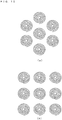
- the number of heating coils may be seven or nine.
- Embodiment 3 and Embodiment 2 may be combined together. Also in this case, similar advantages can be achieved.
Description
- The present invention relates to an induction heating cooker including a plurality of heating coils that are arranged for a single heating port.
- For example, an induction heating cooker has been known that includes a top plate on which a subject to be heated is placed, a plurality of heating coils that are arranged below the top plate so as to be close to one another, a circuit that supplies high-frequency power to each of the heating coils, and load detecting means for detecting, for each of the heating coils, that a subject to be heated is placed thereon (see, for example, Patent Literature 1).
-
Document FR 2 863 039 A1 -
Document EP 0 716 560 A1 discloses a device for induction heating of cooking receptacles, of the type comprising at least two concentric induction coils supplied by a generator. Each induction coil is supplied by a separate generator, the number of induction coils being equal to the number of supply generators. A control block effects the independent operation of each supply generator. The control block is adapted to cause to operate according to a sequential order the supply generators during a detection step of the presence of a load on the corresponding induction coil, starting with the generator corresponding to the innermost concentric induction coil and progressing to the outermost concentric induction coil covered by the receptacle to be heated. The supply generators are identical to each other and have the same nominal power, for the modular replacement of one supply generator by another supply generator of the same characteristics. - In document
WO 2010/128720 A1 a cooking appliance and a control method thereof are provided. A cooking appliance according to an embodiment of the present invention comprises a top plate on which a cooking container is placed, a plurality of winding parts including a plurality of coils horizontally arranged under the top plate, a plurality of relay parts including a plurality of relays that each connected to the plurality of coils, and an inverter part for applying a voltage of high frequency to the plurality of winding parts. - Further induction heating cookers are disclosed e.g. in documents
JP 2009 1 58225 A EP 2 059 091 A2 - Patent Literature 1: Japanese Unexamined Patent Application Publication No.
2008-293871 - With the technology described in
Patent Literature 1, the presence or absence of load is determined for each heating coil, and the circuit supplies high-frequency current only to a heating coil above which the presence of a subject to be heated is detected by the load detecting means. Thus, the heating efficiency in the case of heating a small pan can be improved, and temperature irregularity in the case of heating a large pan can be suppressed. - However, in the state in which a plurality of heating coils are arranged close to one another and high-frequency currents are flowed at the same time to the plurality of heating coils, a problem occur in which due to the influence of magnetic coupling between neighboring heating coils, it is difficult to determine whether or not load to be heated is located above a heating coil and to determine the size of load to be heated, and a situation may occur in which a subject to be cooked cannot be heated at a heating distribution desired by a user.
- In order to overcome the above-described problem, the present invention achieves, in an induction heating cooker including a plurality of heating coils that are arranged for a single heating port, an improved heating distribution in the case where a specific heating mode is selected.
- An induction heating cooker according to the present invention includes a top plate on which a cooking container serving as a subject to be heated is placed; a plurality of heating coils that are arranged below the top plate so as to be close to one another for a single heating port; a plurality of inverter circuits each of which supplies high-frequency power to one of a plurality of load circuits that includes a corresponding one of the heating coils; power detecting means for detecting power output from each of the inverter circuits to a corresponding one of the load circuits or power input to a corresponding one of the inverter circuits; output current detecting means for detecting an output current of each of the inverter circuits; load detecting means for performing load detection on a basis of results of detection by the power detecting means and the output current detecting means; control means for performing driving control for the plurality of inverter circuits on a basis of results of detection by the power detecting means, the output current detecting means, and the load detecting means; and operation means for inputting, to the control circuit, instructions for starting and stopping of heating, setting of heating power, and a heating mode. The load detecting means performs the load detection by separately and individually allowing the load circuits to enter individual conduction states. The control means performs the load detection every time heating power setting is changed, and has a heating mode in which power distribution is set for each of the heating coils or each of the inverter circuits on the basis of the result of load detection.
- According to the present invention, in the case where a specific heating mode is selected by operation means, control means performs control such that every time heating power setting is changed, load detecting means performs load detection by allowing separately and individually allowing the heating coils or inverter circuits to be in individual conduction states, and the control means sets power distribution for each heating coil or each inverter circuit on the basis of a result of load detection. Thus, load detection is not performed in the state in which high-frequency currents are flowed to a plurality of heating coils that are arranged close to one another at the same time. Detection of load to be heated can be performed while suppressing the influence of magnetic coupling between the heating coils, and power distribution to the heating coils is performed on the basis of the result of detection. Thus, a subject to be heated can be heated at a desired heating distribution without being affected by magnetic coupling between heating coils.
-
- [
Fig. 1] Fig. 1 is diagram illustrating the configuration of an induction heating cooker according toEmbodiment 1. - [
Fig. 2] Fig. 2 is a diagram illustrating the circuit configuration of the induction heating cooker according toEmbodiment 1. - [
Fig. 3] Fig. 3 includes diagrams illustrating an example of the arrangement of a plurality of heating coils for a single heating port of the induction heating cooker according toEmbodiment 1. - [
Fig. 4] Fig. 4 is a flowchart illustrating a heating control process performed by control means of the induction heating cooker according toEmbodiment 1. - [
Fig. 5] Fig. 5 is a flowchart illustrating a load detecting process performed by load detecting means in the control means of the induction heating cooker according toEmbodiment 1. - [
Fig. 6] Fig. 6 is a flowchart illustrating a target power distribution process performed by the control means of the induction heating cooker according toEmbodiment 1. - [
Fig. 7] Fig. 7 is a diagram illustrating an example of driving signals to inverter circuits of the Induction heating cooker according toEmbodiment 1. - [
Fig. 8] Fig. 8 is a flowchart illustrating a load detecting process performed by load detecting means in control means of an induction heating cooker according toEmbodiment 2. - [
Fig. 9] Fig. 9 is a diagram illustrating an example of driving signals to inverter circuits of the induction heating cooker according toEmbodiment 2. - [
Fig. 10] Fig. 10 is a flowchart illustrating a heating control process in control means of an induction heating cooker according toEmbodiment 3. - [
Fig. 11] Fig. 11 is a diagram illustrating another circuit configuration of an induction heating cooker according to an embodiment. - [
Fig. 12] Fig. 12 is a diagram illustrating another circuit configuration of an induction heating cooker according to an embodiment. - [
Fig. 13] Fig. 13 includes diagrams illustrating another example of the arrangement of a plurality of heating coils of an induction heating cooker according to an embodiment. -
Fig. 1 is a diagram illustrating the configuration of an induction heating cooker according toEmbodiment 1. - Referring to
Fig. 1 ,numeral 101 denotes a top plate, 102 denotes a main unit casing, 103 denotes a circuit that supplies high-frequency current, 104 denotes an operation unit, 105 denotes display means, and 16 denotes heating coils. - The
top plate 101 is provided so that a subject to be heated, such as a pan, is placed above thetop plate 101, and includesheating ports 106 each representing the location at which a pan is to be placed. Thecircuit 103, the display means 105, and theheating coils 16 are accommodated inside themain unit casing 102. The upper surface of themain unit casing 102 is covered with thetop plate 101, and the inner structure of themain unit casing 102 is accommodated in themain unit casing 102. - The
circuit 103 has the configuration explained later with reference toFig. 2 , and supplies high-frequency current to theheating coils 16. - The
operation unit 104 is provided so that a user adjusts heating output, and the user can select among a plurality of heating modes. For example, the user can select among heating modes, such as a uniform heating mode in which pancakes or the like are baked, a water-boiling mode in which heating efficiency has priority over heating distribution, and the like. Here, high heating efficiency means that the load resistance of a heating coil is large and a large heating output can be obtained by a small coil current. - The display means 105 is a screen display device including a liquid crystal display device or the like, and displays the operation state of the induction heating cooker.
- The plurality of
heating coils 16 are arranged close to one another in association withcorresponding heating ports 106. In this embodiment, fiveheating coils 16 are arranged for each of theheating ports 106. -
Fig. 2 is a diagram illustrating the circuit configuration of a heating port of the induction heating cooker according toEmbodiment 1. The induction heating cooker is connected to an alternating-current power supply 1. Electric power supplied from the alternating-current power supply 1 is converted by a direct-currentpower supply circuit 2 into direct-current power. - The direct-current
power supply circuit 2 includes a rectifyingdiode bridge 3 that rectifies alternating-current power, andreactors 4a to 4e andsmoothing capacitors 5a to 5e that are provided in association withrespective inverter circuits 6a to 6e. As described later, the direct-currentpower supply circuit 2 supplies direct-current power to the plurality ofinverter circuits 6a to 6e, which are provided in association with the number ofload circuits 15a to 15e includingrespective heating coils 16a to 16e. - The
inverter circuits 6a to 6e have the same configuration. Theinverter circuits 6a to 6e include switching elements (upper switches) 7a to 7e and switching elements (lower switches) 8a to 8e that are connected in series between direct-current buses of the direct-currentpower supply circuit 2, anddiodes 9a to 9e and 10a to 10e that are connected in antiparallel to the switching elements. The series of two switching elements are alternately turned on and off at high frequency by drivingcircuits 11a to 11 e, and high-frequency voltage is generated between an output terminal and one end of the direct-current bus. High-frequency voltages output from theinverter circuits 6a to 6e are detected by output voltage detecting means 13a to 13e, and output currents of the inverter circuits are also flowed to the heating coils and are detected by output current detecting means 12a to 12e. Furthermore,reference numerals 14a to 14e denote output power detecting means for generating output power values of the inverter circuits by integrating the output voltage values and the output current values (heating coil current values) detected by the output voltage detecting means 13a to 13e and the output current detecting means 12a to 12e. -
Load circuits 15a to 15e are connected between output terminals of theinverter circuits 6a to 6e and a lower-potential-side bus of the direct-current power supply. Theload circuits 15a to 15e include series circuits of the heating coils 16a to 16e andresonant capacitors 17a to 17e, and clampdiodes 18a to 18e that are connected in parallel to theresonant capacitors 17a to 17e. Theclamp diodes 18a to 18e clamp potentials of connection points of the heating coils 16a to 16e and theresonant capacitors 17a to 17e to the potential of the lower-potential-side bus of the direct-current power supply. Due to the operation of theclamp diodes 18a to 18e, currents flowing in the heating coils 16a to 16e do not commutate in the state in which thelower switches 8a to 8e are connected. - Control means 19 performs driving control for each of the
inverter circuits 6a to 6e. The control means 19 controls the drivingcircuits 11a to 11e, on the basis of output currents and output power of theinverter circuits 6a to 6e. Furthermore, loadresistance detecting means 20 that is provided inside the control means 19 detects load resistances R of theload circuits 15a to 15e, on the basis of the power detected by the output power detecting means 14a to 14e and the currents detected by the output current detecting means 12a to 12e. The loadresistance detecting means 20 constitutes load detecting means. A load resistance R is obtained by the following equation:
- The load resistances R increase or decrease in accordance with loss (heat generation) based on induced eddy currents generated when magnetic fluxes generated by high-frequency currents flowing in the heating coils 15a to 15e are interlinked with the bottom of a pan placed above the heating coils. The load resistance R increases as the size of the bottom of a pan facing a corresponding heating coil increases. Thus, the presence or absence and the size of a pan (load) placed above a corresponding heating coil can be determined on the basis of the value of the load resistance R. Here, in order to distinguish the state in which an appropriate pan is placed above a heating coil from the state in which an appropriate pan is not paced above the heating coil, a threshold R1 is set. Although the threshold R1 varies according to the number of windings of a copper wire of a heating coil, the threshold R1 is set to, for example, about several Ω (2Ω to 5Ω).
-
Fig. 3 illustrates an example of the arrangement of heating coils of the induction heating cooker according toEmbodiment 1. InFig. 3 , (a) is a side view illustrating the arrangement of heating coils, and (b) is a plan view illustrating the arrangement of the heating coils. As illustrated inFig. 3 , the fiveheating coils 16a to 16e are arranged close to one another for a single heating port of the induction heating cooker according to this embodiment, and apan 22, which is a cooking container serving as a subject to be heated, is placed above the heating coils 16a to 16e via thetop plate 101. -
Fig. 4 is a flowchart illustrating a heating control process by the control means 19 of the induction heating cooker according to this embodiment.Fig. 5 is a flowchart illustrating a load detecting process performed by the load detecting means, which detects the presence or absence and the size of a pan (load) above each heating coil.Fig. 6 is a flowchart illustrating a target power distribution process for performing allocation of heating power to be output from heating coils. Hereinafter, the operation performed by the control means of the induction heating cooker according toEmbodiment 1 will be explained with reference to the flowcharts. - Referring to
Fig. 4 , first, the control means 19 determines whether or not an instruction of a heating request for heating power setting or the like has been input from the operation unit 104 (step 1). In the case where a heating request has been input, in order to determine whether a pan to be heated is placed above the heating coils 16a to 16e, the control means 19 performs a load detecting process (step 2). - As illustrated in
Fig. 5 , in the load detecting process, the drivingcircuit 11a is first controlled such that theinverter circuit 6a for theheating coil 16a is driven, and a predetermined high-frequency voltage is applied to theload circuit 15a including theheating coil 16a (step 2-1-1). At this time, control is performed such that high-frequency voltage is not applied to theload circuits 15b to 15e including theother heating coils heating coil 16a and the high-frequency power output from theinverter circuit 6a are detected by the output current detecting means 12a and the output power detecting means 14a (step 2-1-2). The loadresistance detecting means 20 calculates the load resistance R (= W/l2) on the basis of the detected power value W and output current value I (step 2-1-3). Then, it is determined, on the basis of the load resistance R, whether or not an appropriate pan is placed above theheating coil 16a (step 2-1-4). In the case where the load resistance R is smaller than the threshold R1, it is determined that no appropriate load is placed, and resistance data Ra for target power distribution is set to 0 (step 2-1-5). In the case where the load resistance R is equal to or greater then R1, it is determined that theheating coil 16a is in a load state in which load is placed, and the load resistance data Ra for target power distribution is set to be equal to R (step 2-1-6). Then, the inverter circuit load detecting processing for theheating coil 16a (step 2-1) is terminated. - Then, similarly, for each of the heating coils 16b to 16e, it is determined whether an appropriate pan is placed above the heating coil, and in order to acquire load resistance data for target power distribution regarding the size of the placed pan (load) 22, the inverter circuit load detecting processing is performed (steps 2-2 to 2-5). Also at this time, control is performed for each heating coil such that high-frequency voltage is applied only to a load circuit including the heating coil, and high-frequency voltage is not applied to load circuits including the other heating coils.
- Referring back to
Fig. 4 , after the load detecting process (step 2) is terminated, it is determined whether or not a heating coil above which appropriate load is placed exists (step 3). In the case where no heating coil above which appropriate load is placed exists, the process returns to step 1. In the case where a heating coil above which appropriate load is placed exists, a target power distribution process for each of the heating coils 16a to 16e is performed (step 4). - As illustrated in
Fig. 6 , the target power distribution process is performed such that the entire heating power output Wall set by theoperation unit 104 is distributed for target power for the heating coils 16a to 16e, on the basis of load resistance data for the corresponding heating coils. - First, it is determined, for the
heating coil 16a (step 4-1), whether or not appropriate load is placed (step 4-1-1). In the case where no appropriate load is placed, the target power is set to 0 (step 4-1-2). In the case where appropriate load is placed, the target power Wa for theheating coil 16a is set, on the basis of the entire set heating power Wall and load resistances Ra to Re detected by the load detecting means, as represented by the equation (step 4-1-3):
- Similarly, for each of the heating coils 16b to 16e, processing for setting target power is performed (steps 4-2 to 4-5). The target power for each heating coil is set to a value proportional to the load resistance R of the heating coil in the manner as follows:


- By performing setting as described above, in the case where the heating coils 16b to 16e are the same, heating densities [(output of a heating coil / area of a portion of the heating coil that faces a pan)] of the heating coils are the same.
- Referring back to
Fig. 4 , after setting of the target power for each of the heating coils (step 4) is completed, a driving circuit for an inverter circuit for a heating coil above which the presence of appropriate load is determined is controlled, and inverter output is started (step 5). The output current detecting means 12a to 12e and the output power detecting means 14a to 14e detect output currents and power of theinverter circuits 6a to 6e (step 6). Then, output control processing for theinverter circuits 6a to 6e is performed for each of the heating coils 16a to 16e. - In the output control processing for the
heating coil 16a (step 7), first, it is determined whether theinverter circuit 6a is being driven (step 7-1). In the case where theinverter circuit 6a is not being driven, the processing is terminated. In the case where theinverter circuit 6a is being driven, it is determined whether or not output current of theinverter circuit 6a flowing in theheating coil 16a is excessive (step 7-2). In the case where the output current of theinverter circuit 6a is not excessive, the target power Wa for theheating coil 16a is compared with the detected power W (step 7-3). As a result, in the case where the detected power of theheating coil 16a is smaller than the target power, control for increasing the inverter circuit output is performed (step 7-4). In the case where the detected power is substantially equal to the target power, the inverter circuit output is maintained. In the case where it is determined in step 7-2 that the current of theheating coil 16a is excessive or in the case where it is determined in step 7-3 that the detected power W is greater than the target power Wa, control for decreasing the inverter circuit output is performed (step 7-5). - Similarly to the
heating coil 16a, for the other heating coils 16b to 16e, theinverter circuits 6b to 6e are controlled (steps 8 to 11). - Then, it is determined whether or not a heating stop request has been received from the operation unit 104 (step 12). In the case where a stop request has been received, the driving
circuits 11a to 11e are controlled such that driving of all theinverter circuits 6a to 6e is stopped (step 13). Then, the process returns to step 1. - In the case where a heating stop request has not been received in
step 12, it is determined whether or not a set heating power changing request has been received (step 14). In the case where a heating power changing request has not been received, the process returns to step 6. In contrast, in the case where a heating power changing request has been received, it is determined which heating mode has been selected by the operation unit 104 (step 15). In the case where the selected heating mode is a heating mode in which priority is given to heating distribution control (for example, a uniform heating mode (a mode in which the entire bottom of a pan having a large diameter is heated uniformly, a heating mode in which the periphery of a pan is given priority to increase the heating density of outer heating coils so that heating of the periphery of the pan can be increased), or the like), the drivingcircuits 11a to 11e are controlled such that driving of all theinverter circuits 6a to 6e is stopped (step 16). The process returns to the load detecting means ofstep 2, in which the load detecting process is performed for each heating coil, and the load resistances Ra to Re regarding the size of a subject to be heated (pan) above the corresponding heating coils are detected. An example of driving signals for the inverter circuits at this time is illustrated inFig. 7 . - In the case where the heating mode selected in
step 15 is a heating mode in which heating efficiency or operability has priority over heating distribution, the process returns to step 4, in which distribution of heating power is performed on the basis of the load resistances of the heating coils detected at the time of starting heating. - As described above, in this embodiment, the induction heating cooker, in which a plurality of heating coils are arranged adjacent to one another for a single heating port and high-frequency current is flowed only to a heating coil above which a subject to be heated (pan) is placed, has a predetermined heating mode, such as a uniform heating mode, in which load detecting means for each heating coil is performed by stopping concurrent conduction to the plurality of heating coils every time set heating power is changed. Thus, in this heating mode, the presence or absence and the size of a subject to be heated are detected, as required, for each heating coil without being affected by magnetic coupling between heating coils, and controlling is performed such that power distribution is performed at a desired heating distribution. Meanwhile, in the other heating modes, at the time of changing heating power or the like, heating output or heating efficiency is not reduced due to the load detecting means. Therefore, an induction heating cooker that suppresses reductions in the operability and heating efficiency as much as possible while ensuring finishing of cooking corresponding to a heating mode, can be achieved.
-
Fig. 8 is a flowchart illustrating a load detecting process performed by load detecting means in control means of an induction heating cooker according toEmbodiment 2, andFig. 9 illustrates an example of driving signals of the induction heating cooker according toEmbodiment 2. In the load detecting process performed by the load detecting means in the control means of the induction heating cooker according toEmbodiment 1, in order to avoid the influence of magnetic coupling between heating coils that are arranged adjacent to one another, by sequentially causing high-frequency current to be flowed to each load circuit including a heating coil, a subject to be heated (pan) placed above the heating coil is detected. However, inEmbodiment 2, at the time of the load detecting process, by concurrently allowing a pair of load circuits including heating coils that are not adjacent to each other to achieve conduction of high-frequency current, a reduction in the load detection time can be achieved. Similar toEmbodiment 1, the circuit configuration, the arrangement of heating coils, and a heating control process by the control means 19 in the induction heating cooker according toEmbodiment 2 are illustrated inFig. 2 ,Fig. 3 , and the flowchart ofFig. 4 , respectively. - Referring to
Fig. 8 , in the load detecting process inEmbodiment 2, in order to perform load detecting processing for theheating coil 16a (step 2-1), thecontrol circuit 11a is controlled such that theinverter circuit 6a is driven, and a predetermined high-frequency output is performed (step 2-1-1). The high-frequency current and high-frequency power flowing in theheating coil 16a are detected by the output current detecting means 12a and the power detecting means 14a (step 2-1-2). Then, the load resistance R(a) is calculated on the basis of the output current and power detected for theheating coil 16a (step 2-1-3), and in order to determine the presence or absence of load to be heated (pan) above theheating coil 16a, the load resistance R(a) is compared with the load resistance threshold R1 (step 2-1-4). As a result, in the case where the load resistance R(a) is smaller than the threshold R1, it is determined that no load to be heated is placed above theheating coil 16a, and the resistance Ra for heating power distribution is set to 0 (step 2-1-5). In contrast, in the case where the load resistance R(a) is equal to or greater than the threshold R1, it is determined that a subject to be heated is placed above theheating coil 16a, and the resistance Ra for heating power distribution is set to be equal to R(a) (step 2-1-6). - Then, in order to perform load detecting processing (step 2-6) for the
heating coil 16b and theheating coil 16c, which are not adjacent to each other, the drivingcircuits 11b and 11c are controlled such that theinverter circuits 6b and 6c are driven, and predetermined high-frequency outputs are performed (step 2-6-1). The high-frequency currents and the high-frequency power flowing in the heating coils 16b and 16c are detected by the output current detecting means 12b and 12c and the power detecting means 14b and 14c (step 2-6-2). Then, the load resistances R(b) and R(c) are calculated on the basis of the output currents and power detected for the heating coils 16b and 16c (step 2-6-3), and in order to determine the presence or absence of load to be heated (pan) above theheating coil 16b, the load resistance R(b) is compared with the threshold R1 (step 2-6-4). As a result, in the case where the load resistance R(b) is smaller than the threshold R1, it is determined that no load to be heated is placed above theheating coil 16b, and the resistance Rb for heating power distribution is set to 0 (step 2-6-5). In contrast, in the case where the load resistance R(b) is equal to or greater than the threshold R1, it is determined that a subject to be heated is placed above theheating coil 16b, and the resistance Rb for heating power distribution is set to be equal to R(b) (step 2-6-6). - Then, in order to determine the presence or absence of load to be heated (pan) above the
heating coil 16c, the load resistance R(c) is compared with the load resistance threshold R1 (step 2-6-7). As a result, in the case where the load resistance R(c) is smaller than the threshold R1, it is determined that no load to be heated is placed above theheating coil 16c, and the resistance Rc for heating power distribution is set to 0 (step 2-6-8). In contrast, in the case where the load resistance R(c) is equal to or greater than the threshold R1, it is determined that a subject to be heated is placed above theheating coil 16c, and the resistance Rc for heating power distribution is set to be equal to R(c) (step 2-6-9). - Then, similar to the load detecting processing (step 2-6) for the heating coils 16b and 16c, which are not adjacent to each other, in order to perform load detecting processing (step 2-7) for the heating coils 16d and 16e, which are not adjacent to each other, the driving
circuits inverter circuits heating coil 16d and theheating coil 16e are detected by the outputcurrent detecting means power detecting means 14d and 14e (step 2-7-2, not illustrated and corresponding to step 2-6-2). Then, the load resistances R(d) and R(e) are calculated on the basis of the output currents and power detected for the heating coils 16d and 16e (step 2-7-3, not illustrated and corresponding to step 2-6-3), and in order to determine the presence or absence of load to be heated (pan) above theheating coil 16d, the load resistance R(d) is compared with the load resistance threshold R1 (step 2-7-4, not illustrated and corresponding to step 2-6-4). As a result, in the case where the load resistance R(d) is smaller than the threshold R1, it is determined that no load to be heated is placed above theheating coil 16d, and the resistance Rd for heating power distribution is set to 0 (step 2-7-5, not illustrated and corresponding to step 2-6-5). In contrast, in the case where the load resistance R(d) is equal to or greater than the threshold R1, it is determined that a subject to be heated is placed above theheating coil 16d, and the resistance Rd for heating power distribution is set to be equal to R(d) (step 2-7-6, not illustrated and corresponding to step 2-6-7). - Then, in order to determine the presence or absence of load to be heated (pan) above the
heating coil 16e, the load resistance R(e) is compared with the load resistance threshold R1 (step 2-7-7, not illustrated and corresponding to step 2-6-7). As a result, in the case where it is determined that the load resistance R(e) is smaller than the threshold R1, it is determined that no load to be heated is placed above theheating coil 16e, and the resistance Re for heating power distribution is set to 0 (step 2-7-8, not illustrated and corresponding to step 2-6-8). In contrast, in the case where the load resistance R(e) is equal to or greater than the threshold R1, it is determined that a subject to be heated is placed above theheating coil 16e, and the resistance Re for heating power distribution is set to be equal to R(e) (step 2-7-9, not illustrated). -
Fig. 9 illustrates an example of driving signals for theinverter circuits 6a to 6e in the load detecting processes (steps 2-1, 2-6, and 2-7). Since the load detecting process is performed by driving theinverter circuits 6b and 6c at the same time and then driving theinverter circuits Embodiment 1, in which the load detecting process is performed by separately and individually allowing the inverter circuits to enter respective conduction states in a sequential manner. - As described above, in
Embodiment 2, the induction heating cooker, in which a plurality of heating coils are arranged adjacent to one another for a single heating port and high-frequency current is flowed only to a heating coil above which a subject to be heated (pan) is placed, has a predetermined heating mode, such as a uniform heating mode, in which concurrent conduction to the plurality of heating coils is stopped every time set heating power is changed, load detection is performed, for load circuits including heating coils that are adjacent to each other and thus have a large magnetic coupling, by separately and individually allowing each of the load circuits to enter an individual conduction state, and load detection is performed for the load circuits including heating coils that are not adjacent to each other and thus have a small magnetic coupling. Therefore, an induction heating cooker can be achieved in this heating mode in which the load detecting processing time can be reduced while detection of the presence or absence and the size of a subject to be heated for each heating coil being performed without the influence of magnetic coupling between heating coils. -
Fig. 10 is a flowchart illustrating a heating control process performed by control means of an induction heating cooker according toEmbodiment 3. The same processing as that inFig. 4 is referred to with the same step number, and explanation for the same processing will be omitted. Similar toEmbodiment 1, the circuit configuration and the arrangement of heating coils of the induction heating cooker according toEmbodiment 3 are illustrated inFig. 2 andFig. 3 , respectively. - In
step 14 inFig. 10 , it is determined whether or not a set heating power changing request has been received. In the case where a heating power changing request has not been received, it is determined which heating mode has been selected by the operation unit 104 (step 17). In the case where a heating mode in which priority is given to heating distribution control (for example, a uniform heating mode or the like) has been selected, it is determined whether a predetermined time has passed since the execution of the last load detecting process (step 18). In the case where the predetermined time has passed, the process proceeds to step 16, in which driving of all theinverter circuits 6a to 6e is stopped. Then, the process returns to the load detecting means ofstep 2, in which the load detecting process is performed for each heating coil. In the case where the selected heating mode is a heating mode in which heating efficiency or operability has priority over heating distribution instep 17 or in the case where the predetermined time has not passed instep 18, the process returns to step 6, in which output control to the individual heating coils is performed. - As described above, in
Embodiment 3, the induction heating cooker, in which a plurality of heating coils are arranged adjacent to one another for a single heating port and high-frequency current is flowed only to a heating coil above which a subject to be heated (pan) is placed, has a predetermined heating mode, such as a uniform heating mode, in which load detecting means for each heating coil is performed by stopping concurrent conduction to the plurality of heating coils every time set power is changed. Furthermore, in this heating mode, by performing load detecting means for each heating coil by stopping concurrent conduction to the plurality of heating coils at a predetermined time interval, even in the case where a user shakes the pan or displaces the position of the pan during heating in a specific heating mode without an instruction for changing set heating power being received, the presence or absence and the size of the subject to be heated are detected for each heating coil without being affected by magnetic coupling between heating coils, and control is performed such that power distribution is performed at a desired heating distribution. Meanwhile, in the other heating modes, heating output or heating efficiency is not reduced by the load detecting means at the time of changing heating power or the like. Therefore, an induction heating cooker that suppresses reductions in the operability and heating efficiency as much as possible while ensuring finishing of cooking corresponding to a heating mode irrespective of a change in the state of placement of a subject to be heated, can be achieved. - The direct-current
power supply circuit 2 of the induction heating cooker according to the foregoing embodiments includes a single rectifying diode bridge, and output power detecting means for detecting output power of each inverter circuit is provided. However, as illustrated inFig. 11 , the induction heating cooker may have a circuit configuration in which direct-currentpower supply circuits 2a to 2e including rectifying diode bridges for corresponding inverter circuits are provided, and input power values of the inverter circuits are detected by input current detecting means 23a to 23e and input voltage detecting means 24a to 24e. - The circuit configuration (
Fig. 2 ) of the induction heating cooker according to the foregoing embodiments includes the output power detecting means 14 for theinverter circuits 6. However, as illustrated inFig. 11 , the induction heating cooker may have a circuit configuration in which direct-currentpower supply circuits 2 are individually provided for correspondinginverter circuits 6, and input current detecting means 23 and input voltage detecting means 24 for detecting input currents and input voltages to the direct-current power supply circuits are provided. Since values corresponding to the input power input to theinverter circuits 6 are calculated by integrating the input current values and the input voltage values detected by the input current detecting means 23 and the input voltage detecting means 24, the input current detecting means 23 and the input voltage detecting means 24 define input power detecting means. - Furthermore, although an inverter circuit corresponds to a load circuit including a heating coil in the circuit configurations illustrated in
Fig. 2 andFig. 11 of the induction heating cookers according to the foregoing embodiments, a circuit configuration example in which a load circuit includes a plurality of heating coils is possible, as illustrated inFig. 12 . It is desirable that the plurality of heating coils are a pair of heating coils that are not adjacent to each other. Even with this circuit configuration, regarding the resistance of a load circuit for each inverter circuit, by determining the presence or absence of a subject to be heated by individually driving the inverter circuits in a specific heating mode, the presence or absence and the size of a subject to be heated can be accurately determined for each inverter circuit. - Furthermore, in the foregoing embodiments, although the case in which the number of heating coils provided for a single heating port is five has been explained, the number of heating coils is not necessarily five. For example, as illustrated in
Fig. 13 , the number of heating coils may be seven or nine. - The three embodiments described above are not necessarily implemented individually. Any combination of the three embodiments may be implemented. For example,
Embodiment 3 andEmbodiment 2 may be combined together. Also in this case, similar advantages can be achieved. - 1: alternating-current power supply, 2, 2a-2e: direct-current power supply circuit, 3, 3a-3e: rectifying diode bridge, 4a-4e: reactor, 5a-5e: smoothing capacitor, 6a-6e: inverter circuit, 7a-7e: upper switch, 8a-8e: lower switch, 9a-9e, 10a-10e: diode, 11a-11e: driving circuit, 12a-12e: output current detecting means, 13a-13e: output voltage detecting means, 14a-14e: output power detecting means, 15a-15e: load circuit, 16a-16e: heating coil, 17a-17e: resonant capacitor, 18a-18e: clamp diode, 19: control means, 20: load resistance detecting means, 22: cooking container, 23a-23e: input current detecting means, 24a-24e: input voltage detecting means, 101: top plate, 102: main unit casing, 103: circuit, 104: operation unit, 105: operation means, 106: heating port
Claims (5)
- An induction heating cooker comprising:a top plate (101) on which a cooking container (22) serving as a subject to be heated is placed;a plurality of heating coils (16a-16e) that are arranged below the top plate (101) so as to be close to one another for a single heating port (106);a plurality of inverter circuits (6a-6e) that respectively supply high-frequency power to a plurality of load circuits (15a-15e) that include the plurality of heating coils (16a-16e);power detecting means (14a-14e) for detecting power output from the plurality of inverter circuits (6a-6e) to the plurality of load circuits (15a-15e) or power input to the plurality of inverter circuits (6a-6e);output current detecting means (12a-12e) for detecting respective output currents of the plurality of inverter circuits (6a-6e);load detecting means (20) for performing load detection on a basis of results of detection by the power detecting means (14a-14e) and the output current detecting means (12a-12e);control means (19) for performing driving control for the plurality of inverter circuits (6a-6e) on a basis of results of detection by the power detecting means (14a-14e), the output current detecting means (12a-12e), and the load detecting means (20); andoperation means (104) for inputting, to the control means (19), instructions for starting and stopping of heating, setting of heating power, and a heating mode,wherein the load detecting means (20) performs the load detection by separately and individually allowing the load circuits (15a-15e) to enter individual conduction states, and
characterised in that the load detecting means (20) performs the load detection every time heating power setting is changed, and the control means (19) has a heating mode in which power distribution is set for each of the heating coils (16a-16e) or each of the inverter circuits (6a-6e) on a basis of a result of the load detection,
and in that the plurality of load circuits (15a-15e) include one of a plurality of load circuits that includes a plurality of heating coils that are not adjacent to each other. - The induction heating cooker of claim 1, wherein the load detecting means (20) performs the load detection at a predetermined time interval, and the control means (19) has a heating mode in which the power distribution is set for each of the heating coils (16a-16e) or each of the inverter circuits (6a-6e) on the basis of the result of load detection.
- An induction heating cooker comprising:a top plate (104) on which a cooking container (22) serving as a subject to be heated is placed;a plurality of heating coils (16a-16e) that are arranged below the top plate so as to be close to one another for a single heating port (106);a plurality of inverter circuits (6a-6e) that respectively supply high-frequency power to a plurality of load circuits (15a-15e) that include the plurality of heating coils (16a-16e);power detecting means (14a-14e) for detecting power output from the plurality of inverter circuits (6a-6e) to the plurality of load circuits (15a-15e) or power input to the plurality of inverter circuits (6a-6e);output current detecting means (12a-12e) for detecting output currents of the plurality of the inverter circuits (6a-6e);load detecting means (20) for performing load detection on a basis of results of detection by the power detecting means (14a-14e) and the output current detecting means (12a-12e);control means (19) for performing driving control for the plurality of inverter circuits (6a-6e) on a basis of results of detection by the power detecting means (14a-14e), the output current detecting means (12a-12e), and the load detecting means (20); andoperation means (104) for inputting, to the control means (19), instructions for starting and stopping of heating, setting of heating power, and a heating mode,wherein the load detecting means (20) performs the load detection for a part of the plurality of load circuits (15) including a heating coil (16a) that is adjacent to another at least one of the heating coils (16b-16e) by separately and individually allowing a part of the load circuits (15a) to enter an individual conduction state, and characterised in that it performs a load detection for another part of the load circuits (15b, 15c)(15d, 15e) including those of heating coils (16b, 16c)(16d, 16e) that are not adjacent to each other, by concurrently allowing, in a sequential manner, each pair of the another part of the load circuits (15b, 15c)(15d, 15e) to enter a conduction state, and
in that the load detecting means (20) performs the load detection every time heating power setting is changed, and the control means (19) has a heating mode in which power distribution is set for each of the heating coils (16a-16e) or each of the inverter circuits (6a-6e) on a basis of a result of the load detection. - The induction heating cooker of claim 3, wherein the load detecting means (20) performs the load detection at a predetermined time interval, and the control means (19) has a heating mode in which the power distribution is set for each of the heating coils (16a-16e) or each of the inverter circuits (6a-6e) on the basis of the result of load detection.
- The induction heating cooker of any one of claims 3 or 4, wherein the plurality of load circuits (15a-15e) include one of a plurality of load circuits that includes a plurality of the heating coils that are not adjacent to each other.
Applications Claiming Priority (2)
| Application Number | Priority Date | Filing Date | Title |
|---|---|---|---|
| JP2011204220 | 2011-09-20 | ||
| PCT/JP2012/002527 WO2013042288A1 (en) | 2011-09-20 | 2012-04-12 | Induction heating cooker |
Publications (3)
| Publication Number | Publication Date |
|---|---|
| EP2760251A1 EP2760251A1 (en) | 2014-07-30 |
| EP2760251A4 EP2760251A4 (en) | 2015-09-09 |
| EP2760251B1 true EP2760251B1 (en) | 2018-11-14 |
Family
ID=47914082
Family Applications (1)
| Application Number | Title | Priority Date | Filing Date |
|---|---|---|---|
| EP12834381.1A Not-in-force EP2760251B1 (en) | 2011-09-20 | 2012-04-12 | Induction heating cooker |
Country Status (3)
| Country | Link |
|---|---|
| EP (1) | EP2760251B1 (en) |
| JP (3) | JP5711379B2 (en) |
| WO (1) | WO2013042288A1 (en) |
Families Citing this family (5)
| Publication number | Priority date | Publication date | Assignee | Title |
|---|---|---|---|---|
| JP6817510B2 (en) * | 2015-05-14 | 2021-01-20 | パナソニックIpマネジメント株式会社 | Induction heating cooker |
| TR201809520T4 (en) * | 2015-12-18 | 2018-07-23 | Ego Elektro Geraetebau Gmbh | Heating circuit and induction cooking stove. |
| CN108064096A (en) * | 2016-11-09 | 2018-05-22 | 中山市通威电器有限公司 | A kind of electromagnetic heating disk |
| KR20180065814A (en) | 2016-12-08 | 2018-06-18 | 삼성전자주식회사 | Cooking apparatus |
| CN109945248B (en) * | 2017-12-21 | 2020-06-05 | 佛山市顺德区美的电热电器制造有限公司 | Electromagnetic cooking appliance and power control method thereof |
Family Cites Families (12)
| Publication number | Priority date | Publication date | Assignee | Title |
|---|---|---|---|---|
| JPH05166579A (en) * | 1991-12-17 | 1993-07-02 | Matsushita Electric Ind Co Ltd | Induction heating cooker |
| FR2728132A1 (en) * | 1994-12-09 | 1996-06-14 | Bonnet Sa | DEVICE FOR HEATING BY INDUCTION OF CONTAINER AND METHOD FOR CONTROLLING SUCH A DEVICE |
| JP3725249B2 (en) * | 1996-07-10 | 2005-12-07 | 島田理化工業株式会社 | Induction heating device |
| FR2863039B1 (en) * | 2003-11-27 | 2006-02-17 | Brandt Ind | METHOD FOR HEATING A CONTAINER POSITIONED ON A COOKTOP HAVING HEATING MEANS ASSOCIATED WITH INDUCERS |
| JP5197693B2 (en) * | 2006-03-30 | 2013-05-15 | 三菱電機株式会社 | Induction heating cooker |
| JP4854596B2 (en) * | 2007-05-28 | 2012-01-18 | 三菱電機株式会社 | Induction heating cooker |
| JP4863961B2 (en) * | 2007-10-15 | 2012-01-25 | 三菱電機株式会社 | Induction heating cooker |
| KR20090048789A (en) * | 2007-11-12 | 2009-05-15 | 삼성전자주식회사 | Induction heating cooker |
| JP4804450B2 (en) * | 2007-12-26 | 2011-11-02 | 三菱電機株式会社 | Induction heating cooker |
| JP5332839B2 (en) * | 2009-04-08 | 2013-11-06 | パナソニック株式会社 | Induction heating cooker |
| KR101535145B1 (en) * | 2009-05-04 | 2015-07-08 | 엘지전자 주식회사 | Cooker and controlling method thereof |
| JP5355442B2 (en) * | 2010-02-09 | 2013-11-27 | 三菱電機株式会社 | Induction heating cooker |
-
2012
- 2012-04-12 EP EP12834381.1A patent/EP2760251B1/en not_active Not-in-force
- 2012-04-12 WO PCT/JP2012/002527 patent/WO2013042288A1/en unknown
- 2012-04-12 JP JP2013534569A patent/JP5711379B2/en active Active
-
2015
- 2015-03-05 JP JP2015043773A patent/JP6005198B2/en active Active
- 2015-03-05 JP JP2015043772A patent/JP6005197B2/en active Active
Non-Patent Citations (1)
| Title |
|---|
| None * |
Also Published As
| Publication number | Publication date |
|---|---|
| JP2015144130A (en) | 2015-08-06 |
| JP2015128078A (en) | 2015-07-09 |
| JP5711379B2 (en) | 2015-04-30 |
| WO2013042288A1 (en) | 2013-03-28 |
| EP2760251A4 (en) | 2015-09-09 |
| JPWO2013042288A1 (en) | 2015-03-26 |
| JP6005197B2 (en) | 2016-10-12 |
| EP2760251A1 (en) | 2014-07-30 |
| JP6005198B2 (en) | 2016-10-12 |
Similar Documents
| Publication | Publication Date | Title |
|---|---|---|
| EP2760251B1 (en) | Induction heating cooker | |
| EP2528412B1 (en) | Induction heating apparatus | |
| EP2405715B1 (en) | Induction-heating cooking system | |
| EP2914059B1 (en) | Induction heating device | |
| EP2790466B1 (en) | Induction heating device | |
| EP2506668A2 (en) | Control method of induction heating cooker | |
| CN110014886A (en) | On-board charging system | |
| CN103348765A (en) | Inductive heating cooker | |
| JP5642289B2 (en) | Induction heating cooker | |
| US10893579B2 (en) | Method for operating an induction cooking hob and cooking hob using such method | |
| CN109479347B (en) | Method for controlling an induction hob | |
| EP3606287A1 (en) | Induction heating cooker | |
| EP3927114B1 (en) | Induction heating cooker | |
| JP2003151751A (en) | Induction heating cooker | |
| JP5642035B2 (en) | Induction heating cooker | |
| EP3709769B1 (en) | Induction-heating cooker | |
| EP2693838B1 (en) | Induction heat cooker | |
| JP5058296B2 (en) | Induction heating cooker | |
| CN102907171B (en) | Induction cooking device | |
| KR102165579B1 (en) | Induction heating device including different types of inverter circuits | |
| KR100202590B1 (en) | Half bridge type induction heating cooker | |
| EP4213592A1 (en) | Heat cooker and heat cooker system | |
| KR101846358B1 (en) | Electric range having multiple inverter circuits driven by same frequency and control method for the electric range | |
| JP2020177871A (en) | Induction cooker | |
| JP2016072172A (en) | Induction heating cooker |
Legal Events
| Date | Code | Title | Description |
|---|---|---|---|
| PUAI | Public reference made under article 153(3) epc to a published international application that has entered the european phase |
Free format text: ORIGINAL CODE: 0009012 |
|
| 17P | Request for examination filed |
Effective date: 20140220 |
|
| AK | Designated contracting states |
Kind code of ref document: A1 Designated state(s): AL AT BE BG CH CY CZ DE DK EE ES FI FR GB GR HR HU IE IS IT LI LT LU LV MC MK MT NL NO PL PT RO RS SE SI SK SM TR |
|
| DAX | Request for extension of the european patent (deleted) | ||
| RA4 | Supplementary search report drawn up and despatched (corrected) |
Effective date: 20150812 |
|
| RIC1 | Information provided on ipc code assigned before grant |
Ipc: H05B 6/06 20060101AFI20150806BHEP |
|
| REG | Reference to a national code |
Ref country code: DE Ref legal event code: R079 Ref document number: 602012053599 Country of ref document: DE Free format text: PREVIOUS MAIN CLASS: H05B0006120000 Ipc: H05B0006060000 |
|
| GRAP | Despatch of communication of intention to grant a patent |
Free format text: ORIGINAL CODE: EPIDOSNIGR1 |
|
| STAA | Information on the status of an ep patent application or granted ep patent |
Free format text: STATUS: GRANT OF PATENT IS INTENDED |
|
| RIC1 | Information provided on ipc code assigned before grant |
Ipc: H05B 6/06 20060101AFI20180430BHEP |
|
| INTG | Intention to grant announced |
Effective date: 20180523 |
|
| GRAS | Grant fee paid |
Free format text: ORIGINAL CODE: EPIDOSNIGR3 |
|
| GRAA | (expected) grant |
Free format text: ORIGINAL CODE: 0009210 |
|
| STAA | Information on the status of an ep patent application or granted ep patent |
Free format text: STATUS: THE PATENT HAS BEEN GRANTED |
|
| AK | Designated contracting states |
Kind code of ref document: B1 Designated state(s): AL AT BE BG CH CY CZ DE DK EE ES FI FR GB GR HR HU IE IS IT LI LT LU LV MC MK MT NL NO PL PT RO RS SE SI SK SM TR |
|
| REG | Reference to a national code |
Ref country code: CH Ref legal event code: EP Ref country code: AT Ref legal event code: REF Ref document number: 1066371 Country of ref document: AT Kind code of ref document: T Effective date: 20181115 |
|
| REG | Reference to a national code |
Ref country code: IE Ref legal event code: FG4D |
|
| REG | Reference to a national code |
Ref country code: DE Ref legal event code: R096 Ref document number: 602012053599 Country of ref document: DE |
|
| REG | Reference to a national code |
Ref country code: SE Ref legal event code: TRGR |
|
| REG | Reference to a national code |
Ref country code: NL Ref legal event code: MP Effective date: 20181114 |
|
| REG | Reference to a national code |
Ref country code: LT Ref legal event code: MG4D |
|
| REG | Reference to a national code |
Ref country code: AT Ref legal event code: MK05 Ref document number: 1066371 Country of ref document: AT Kind code of ref document: T Effective date: 20181114 |
|
| PG25 | Lapsed in a contracting state [announced via postgrant information from national office to epo] |
Ref country code: ES Free format text: LAPSE BECAUSE OF FAILURE TO SUBMIT A TRANSLATION OF THE DESCRIPTION OR TO PAY THE FEE WITHIN THE PRESCRIBED TIME-LIMIT Effective date: 20181114 Ref country code: FI Free format text: LAPSE BECAUSE OF FAILURE TO SUBMIT A TRANSLATION OF THE DESCRIPTION OR TO PAY THE FEE WITHIN THE PRESCRIBED TIME-LIMIT Effective date: 20181114 Ref country code: LV Free format text: LAPSE BECAUSE OF FAILURE TO SUBMIT A TRANSLATION OF THE DESCRIPTION OR TO PAY THE FEE WITHIN THE PRESCRIBED TIME-LIMIT Effective date: 20181114 Ref country code: LT Free format text: LAPSE BECAUSE OF FAILURE TO SUBMIT A TRANSLATION OF THE DESCRIPTION OR TO PAY THE FEE WITHIN THE PRESCRIBED TIME-LIMIT Effective date: 20181114 Ref country code: NO Free format text: LAPSE BECAUSE OF FAILURE TO SUBMIT A TRANSLATION OF THE DESCRIPTION OR TO PAY THE FEE WITHIN THE PRESCRIBED TIME-LIMIT Effective date: 20190214 Ref country code: HR Free format text: LAPSE BECAUSE OF FAILURE TO SUBMIT A TRANSLATION OF THE DESCRIPTION OR TO PAY THE FEE WITHIN THE PRESCRIBED TIME-LIMIT Effective date: 20181114 Ref country code: BG Free format text: LAPSE BECAUSE OF FAILURE TO SUBMIT A TRANSLATION OF THE DESCRIPTION OR TO PAY THE FEE WITHIN THE PRESCRIBED TIME-LIMIT Effective date: 20190214 Ref country code: IS Free format text: LAPSE BECAUSE OF FAILURE TO SUBMIT A TRANSLATION OF THE DESCRIPTION OR TO PAY THE FEE WITHIN THE PRESCRIBED TIME-LIMIT Effective date: 20190314 Ref country code: AT Free format text: LAPSE BECAUSE OF FAILURE TO SUBMIT A TRANSLATION OF THE DESCRIPTION OR TO PAY THE FEE WITHIN THE PRESCRIBED TIME-LIMIT Effective date: 20181114 |
|
| PG25 | Lapsed in a contracting state [announced via postgrant information from national office to epo] |
Ref country code: AL Free format text: LAPSE BECAUSE OF FAILURE TO SUBMIT A TRANSLATION OF THE DESCRIPTION OR TO PAY THE FEE WITHIN THE PRESCRIBED TIME-LIMIT Effective date: 20181114 Ref country code: RS Free format text: LAPSE BECAUSE OF FAILURE TO SUBMIT A TRANSLATION OF THE DESCRIPTION OR TO PAY THE FEE WITHIN THE PRESCRIBED TIME-LIMIT Effective date: 20181114 Ref country code: PT Free format text: LAPSE BECAUSE OF FAILURE TO SUBMIT A TRANSLATION OF THE DESCRIPTION OR TO PAY THE FEE WITHIN THE PRESCRIBED TIME-LIMIT Effective date: 20190314 Ref country code: NL Free format text: LAPSE BECAUSE OF FAILURE TO SUBMIT A TRANSLATION OF THE DESCRIPTION OR TO PAY THE FEE WITHIN THE PRESCRIBED TIME-LIMIT Effective date: 20181114 Ref country code: GR Free format text: LAPSE BECAUSE OF FAILURE TO SUBMIT A TRANSLATION OF THE DESCRIPTION OR TO PAY THE FEE WITHIN THE PRESCRIBED TIME-LIMIT Effective date: 20190215 |
|
| PG25 | Lapsed in a contracting state [announced via postgrant information from national office to epo] |
Ref country code: CZ Free format text: LAPSE BECAUSE OF FAILURE TO SUBMIT A TRANSLATION OF THE DESCRIPTION OR TO PAY THE FEE WITHIN THE PRESCRIBED TIME-LIMIT Effective date: 20181114 Ref country code: IT Free format text: LAPSE BECAUSE OF FAILURE TO SUBMIT A TRANSLATION OF THE DESCRIPTION OR TO PAY THE FEE WITHIN THE PRESCRIBED TIME-LIMIT Effective date: 20181114 Ref country code: PL Free format text: LAPSE BECAUSE OF FAILURE TO SUBMIT A TRANSLATION OF THE DESCRIPTION OR TO PAY THE FEE WITHIN THE PRESCRIBED TIME-LIMIT Effective date: 20181114 Ref country code: DK Free format text: LAPSE BECAUSE OF FAILURE TO SUBMIT A TRANSLATION OF THE DESCRIPTION OR TO PAY THE FEE WITHIN THE PRESCRIBED TIME-LIMIT Effective date: 20181114 |
|
| REG | Reference to a national code |
Ref country code: DE Ref legal event code: R097 Ref document number: 602012053599 Country of ref document: DE |
|
| PG25 | Lapsed in a contracting state [announced via postgrant information from national office to epo] |
Ref country code: SM Free format text: LAPSE BECAUSE OF FAILURE TO SUBMIT A TRANSLATION OF THE DESCRIPTION OR TO PAY THE FEE WITHIN THE PRESCRIBED TIME-LIMIT Effective date: 20181114 Ref country code: EE Free format text: LAPSE BECAUSE OF FAILURE TO SUBMIT A TRANSLATION OF THE DESCRIPTION OR TO PAY THE FEE WITHIN THE PRESCRIBED TIME-LIMIT Effective date: 20181114 Ref country code: SK Free format text: LAPSE BECAUSE OF FAILURE TO SUBMIT A TRANSLATION OF THE DESCRIPTION OR TO PAY THE FEE WITHIN THE PRESCRIBED TIME-LIMIT Effective date: 20181114 Ref country code: RO Free format text: LAPSE BECAUSE OF FAILURE TO SUBMIT A TRANSLATION OF THE DESCRIPTION OR TO PAY THE FEE WITHIN THE PRESCRIBED TIME-LIMIT Effective date: 20181114 |
|
| PLBE | No opposition filed within time limit |
Free format text: ORIGINAL CODE: 0009261 |
|
| STAA | Information on the status of an ep patent application or granted ep patent |
Free format text: STATUS: NO OPPOSITION FILED WITHIN TIME LIMIT |
|
| 26N | No opposition filed |
Effective date: 20190815 |
|
| PG25 | Lapsed in a contracting state [announced via postgrant information from national office to epo] |
Ref country code: SI Free format text: LAPSE BECAUSE OF FAILURE TO SUBMIT A TRANSLATION OF THE DESCRIPTION OR TO PAY THE FEE WITHIN THE PRESCRIBED TIME-LIMIT Effective date: 20181114 |
|
| REG | Reference to a national code |
Ref country code: CH Ref legal event code: PL |
|
| REG | Reference to a national code |
Ref country code: BE Ref legal event code: MM Effective date: 20190430 |
|
| GBPC | Gb: european patent ceased through non-payment of renewal fee |
Effective date: 20190412 |
|
| PG25 | Lapsed in a contracting state [announced via postgrant information from national office to epo] |
Ref country code: LU Free format text: LAPSE BECAUSE OF NON-PAYMENT OF DUE FEES Effective date: 20190412 Ref country code: MC Free format text: LAPSE BECAUSE OF FAILURE TO SUBMIT A TRANSLATION OF THE DESCRIPTION OR TO PAY THE FEE WITHIN THE PRESCRIBED TIME-LIMIT Effective date: 20181114 |
|
| PG25 | Lapsed in a contracting state [announced via postgrant information from national office to epo] |
Ref country code: GB Free format text: LAPSE BECAUSE OF NON-PAYMENT OF DUE FEES Effective date: 20190412 Ref country code: LI Free format text: LAPSE BECAUSE OF NON-PAYMENT OF DUE FEES Effective date: 20190430 Ref country code: CH Free format text: LAPSE BECAUSE OF NON-PAYMENT OF DUE FEES Effective date: 20190430 |
|
| PG25 | Lapsed in a contracting state [announced via postgrant information from national office to epo] |
Ref country code: BE Free format text: LAPSE BECAUSE OF NON-PAYMENT OF DUE FEES Effective date: 20190430 Ref country code: FR Free format text: LAPSE BECAUSE OF NON-PAYMENT OF DUE FEES Effective date: 20190430 |
|
| PG25 | Lapsed in a contracting state [announced via postgrant information from national office to epo] |
Ref country code: TR Free format text: LAPSE BECAUSE OF FAILURE TO SUBMIT A TRANSLATION OF THE DESCRIPTION OR TO PAY THE FEE WITHIN THE PRESCRIBED TIME-LIMIT Effective date: 20181114 |
|
| PG25 | Lapsed in a contracting state [announced via postgrant information from national office to epo] |
Ref country code: IE Free format text: LAPSE BECAUSE OF NON-PAYMENT OF DUE FEES Effective date: 20190412 |
|
| PGFP | Annual fee paid to national office [announced via postgrant information from national office to epo] |
Ref country code: DE Payment date: 20200331 Year of fee payment: 9 |
|
| PGFP | Annual fee paid to national office [announced via postgrant information from national office to epo] |
Ref country code: SE Payment date: 20200415 Year of fee payment: 9 |
|
| PG25 | Lapsed in a contracting state [announced via postgrant information from national office to epo] |
Ref country code: CY Free format text: LAPSE BECAUSE OF FAILURE TO SUBMIT A TRANSLATION OF THE DESCRIPTION OR TO PAY THE FEE WITHIN THE PRESCRIBED TIME-LIMIT Effective date: 20181114 |
|
| PG25 | Lapsed in a contracting state [announced via postgrant information from national office to epo] |
Ref country code: HU Free format text: LAPSE BECAUSE OF FAILURE TO SUBMIT A TRANSLATION OF THE DESCRIPTION OR TO PAY THE FEE WITHIN THE PRESCRIBED TIME-LIMIT; INVALID AB INITIO Effective date: 20120412 Ref country code: MT Free format text: LAPSE BECAUSE OF FAILURE TO SUBMIT A TRANSLATION OF THE DESCRIPTION OR TO PAY THE FEE WITHIN THE PRESCRIBED TIME-LIMIT Effective date: 20181114 |
|
| REG | Reference to a national code |
Ref country code: DE Ref legal event code: R119 Ref document number: 602012053599 Country of ref document: DE |
|
| REG | Reference to a national code |
Ref country code: SE Ref legal event code: EUG |
|
| PG25 | Lapsed in a contracting state [announced via postgrant information from national office to epo] |
Ref country code: DE Free format text: LAPSE BECAUSE OF NON-PAYMENT OF DUE FEES Effective date: 20211103 Ref country code: SE Free format text: LAPSE BECAUSE OF NON-PAYMENT OF DUE FEES Effective date: 20210413 |
|
| PG25 | Lapsed in a contracting state [announced via postgrant information from national office to epo] |
Ref country code: MK Free format text: LAPSE BECAUSE OF FAILURE TO SUBMIT A TRANSLATION OF THE DESCRIPTION OR TO PAY THE FEE WITHIN THE PRESCRIBED TIME-LIMIT Effective date: 20181114 |