EP2759517A1 - Exhaust gas purifier - Google Patents
Exhaust gas purifier Download PDFInfo
- Publication number
- EP2759517A1 EP2759517A1 EP12834338.1A EP12834338A EP2759517A1 EP 2759517 A1 EP2759517 A1 EP 2759517A1 EP 12834338 A EP12834338 A EP 12834338A EP 2759517 A1 EP2759517 A1 EP 2759517A1
- Authority
- EP
- European Patent Office
- Prior art keywords
- ozone
- air
- sensor
- nitrogen
- dryer
- Prior art date
- Legal status (The legal status is an assumption and is not a legal conclusion. Google has not performed a legal analysis and makes no representation as to the accuracy of the status listed.)
- Withdrawn
Links
Images




Classifications
-
- B—PERFORMING OPERATIONS; TRANSPORTING
- B01—PHYSICAL OR CHEMICAL PROCESSES OR APPARATUS IN GENERAL
- B01D—SEPARATION
- B01D53/00—Separation of gases or vapours; Recovering vapours of volatile solvents from gases; Chemical or biological purification of waste gases, e.g. engine exhaust gases, smoke, fumes, flue gases, aerosols
- B01D53/34—Chemical or biological purification of waste gases
- B01D53/92—Chemical or biological purification of waste gases of engine exhaust gases
- B01D53/94—Chemical or biological purification of waste gases of engine exhaust gases by catalytic processes
- B01D53/9495—Controlling the catalytic process
-
- B—PERFORMING OPERATIONS; TRANSPORTING
- B01—PHYSICAL OR CHEMICAL PROCESSES OR APPARATUS IN GENERAL
- B01D—SEPARATION
- B01D53/00—Separation of gases or vapours; Recovering vapours of volatile solvents from gases; Chemical or biological purification of waste gases, e.g. engine exhaust gases, smoke, fumes, flue gases, aerosols
- B01D53/22—Separation of gases or vapours; Recovering vapours of volatile solvents from gases; Chemical or biological purification of waste gases, e.g. engine exhaust gases, smoke, fumes, flue gases, aerosols by diffusion
-
- B—PERFORMING OPERATIONS; TRANSPORTING
- B01—PHYSICAL OR CHEMICAL PROCESSES OR APPARATUS IN GENERAL
- B01D—SEPARATION
- B01D53/00—Separation of gases or vapours; Recovering vapours of volatile solvents from gases; Chemical or biological purification of waste gases, e.g. engine exhaust gases, smoke, fumes, flue gases, aerosols
- B01D53/34—Chemical or biological purification of waste gases
- B01D53/92—Chemical or biological purification of waste gases of engine exhaust gases
- B01D53/94—Chemical or biological purification of waste gases of engine exhaust gases by catalytic processes
- B01D53/9404—Removing only nitrogen compounds
- B01D53/9409—Nitrogen oxides
-
- B—PERFORMING OPERATIONS; TRANSPORTING
- B01—PHYSICAL OR CHEMICAL PROCESSES OR APPARATUS IN GENERAL
- B01D—SEPARATION
- B01D63/00—Apparatus in general for separation processes using semi-permeable membranes
- B01D63/02—Hollow fibre modules
- B01D63/031—Two or more types of hollow fibres within one bundle or within one potting or tube-sheet
-
- B—PERFORMING OPERATIONS; TRANSPORTING
- B01—PHYSICAL OR CHEMICAL PROCESSES OR APPARATUS IN GENERAL
- B01D—SEPARATION
- B01D71/00—Semi-permeable membranes for separation processes or apparatus characterised by the material; Manufacturing processes specially adapted therefor
- B01D71/06—Organic material
- B01D71/58—Other polymers having nitrogen in the main chain, with or without oxygen or carbon only
- B01D71/62—Polycondensates having nitrogen-containing heterocyclic rings in the main chain
- B01D71/64—Polyimides; Polyamide-imides; Polyester-imides; Polyamide acids or similar polyimide precursors
-
- C—CHEMISTRY; METALLURGY
- C01—INORGANIC CHEMISTRY
- C01B—NON-METALLIC ELEMENTS; COMPOUNDS THEREOF; METALLOIDS OR COMPOUNDS THEREOF NOT COVERED BY SUBCLASS C01C
- C01B13/00—Oxygen; Ozone; Oxides or hydroxides in general
- C01B13/10—Preparation of ozone
-
- F—MECHANICAL ENGINEERING; LIGHTING; HEATING; WEAPONS; BLASTING
- F01—MACHINES OR ENGINES IN GENERAL; ENGINE PLANTS IN GENERAL; STEAM ENGINES
- F01N—GAS-FLOW SILENCERS OR EXHAUST APPARATUS FOR MACHINES OR ENGINES IN GENERAL; GAS-FLOW SILENCERS OR EXHAUST APPARATUS FOR INTERNAL-COMBUSTION ENGINES
- F01N3/00—Exhaust or silencing apparatus having means for purifying, rendering innocuous, or otherwise treating exhaust
- F01N3/02—Exhaust or silencing apparatus having means for purifying, rendering innocuous, or otherwise treating exhaust for cooling, or for removing solid constituents of, exhaust
- F01N3/021—Exhaust or silencing apparatus having means for purifying, rendering innocuous, or otherwise treating exhaust for cooling, or for removing solid constituents of, exhaust by means of filters
- F01N3/033—Exhaust or silencing apparatus having means for purifying, rendering innocuous, or otherwise treating exhaust for cooling, or for removing solid constituents of, exhaust by means of filters in combination with other devices
- F01N3/035—Exhaust or silencing apparatus having means for purifying, rendering innocuous, or otherwise treating exhaust for cooling, or for removing solid constituents of, exhaust by means of filters in combination with other devices with catalytic reactors
-
- F—MECHANICAL ENGINEERING; LIGHTING; HEATING; WEAPONS; BLASTING
- F01—MACHINES OR ENGINES IN GENERAL; ENGINE PLANTS IN GENERAL; STEAM ENGINES
- F01N—GAS-FLOW SILENCERS OR EXHAUST APPARATUS FOR MACHINES OR ENGINES IN GENERAL; GAS-FLOW SILENCERS OR EXHAUST APPARATUS FOR INTERNAL-COMBUSTION ENGINES
- F01N3/00—Exhaust or silencing apparatus having means for purifying, rendering innocuous, or otherwise treating exhaust
- F01N3/08—Exhaust or silencing apparatus having means for purifying, rendering innocuous, or otherwise treating exhaust for rendering innocuous
- F01N3/10—Exhaust or silencing apparatus having means for purifying, rendering innocuous, or otherwise treating exhaust for rendering innocuous by thermal or catalytic conversion of noxious components of exhaust
- F01N3/18—Exhaust or silencing apparatus having means for purifying, rendering innocuous, or otherwise treating exhaust for rendering innocuous by thermal or catalytic conversion of noxious components of exhaust characterised by methods of operation; Control
- F01N3/20—Exhaust or silencing apparatus having means for purifying, rendering innocuous, or otherwise treating exhaust for rendering innocuous by thermal or catalytic conversion of noxious components of exhaust characterised by methods of operation; Control specially adapted for catalytic conversion
- F01N3/206—Adding periodically or continuously substances to exhaust gases for promoting purification, e.g. catalytic material in liquid form, NOx reducing agents
- F01N3/208—Control of selective catalytic reduction [SCR], e.g. by adjusting the dosing of reducing agent
-
- B—PERFORMING OPERATIONS; TRANSPORTING
- B01—PHYSICAL OR CHEMICAL PROCESSES OR APPARATUS IN GENERAL
- B01D—SEPARATION
- B01D2251/00—Reactants
- B01D2251/10—Oxidants
- B01D2251/104—Ozone
-
- B—PERFORMING OPERATIONS; TRANSPORTING
- B01—PHYSICAL OR CHEMICAL PROCESSES OR APPARATUS IN GENERAL
- B01D—SEPARATION
- B01D2251/00—Reactants
- B01D2251/20—Reductants
- B01D2251/206—Ammonium compounds
- B01D2251/2067—Urea
-
- B—PERFORMING OPERATIONS; TRANSPORTING
- B01—PHYSICAL OR CHEMICAL PROCESSES OR APPARATUS IN GENERAL
- B01D—SEPARATION
- B01D2255/00—Catalysts
- B01D2255/20—Metals or compounds thereof
- B01D2255/207—Transition metals
- B01D2255/20738—Iron
-
- B—PERFORMING OPERATIONS; TRANSPORTING
- B01—PHYSICAL OR CHEMICAL PROCESSES OR APPARATUS IN GENERAL
- B01D—SEPARATION
- B01D2255/00—Catalysts
- B01D2255/20—Metals or compounds thereof
- B01D2255/207—Transition metals
- B01D2255/20746—Cobalt
-
- B—PERFORMING OPERATIONS; TRANSPORTING
- B01—PHYSICAL OR CHEMICAL PROCESSES OR APPARATUS IN GENERAL
- B01D—SEPARATION
- B01D2255/00—Catalysts
- B01D2255/20—Metals or compounds thereof
- B01D2255/207—Transition metals
- B01D2255/20761—Copper
-
- B—PERFORMING OPERATIONS; TRANSPORTING
- B01—PHYSICAL OR CHEMICAL PROCESSES OR APPARATUS IN GENERAL
- B01D—SEPARATION
- B01D2255/00—Catalysts
- B01D2255/20—Metals or compounds thereof
- B01D2255/207—Transition metals
- B01D2255/20792—Zinc
-
- B—PERFORMING OPERATIONS; TRANSPORTING
- B01—PHYSICAL OR CHEMICAL PROCESSES OR APPARATUS IN GENERAL
- B01D—SEPARATION
- B01D2255/00—Catalysts
- B01D2255/50—Zeolites
-
- B—PERFORMING OPERATIONS; TRANSPORTING
- B01—PHYSICAL OR CHEMICAL PROCESSES OR APPARATUS IN GENERAL
- B01D—SEPARATION
- B01D2256/00—Main component in the product gas stream after treatment
- B01D2256/12—Oxygen
-
- B—PERFORMING OPERATIONS; TRANSPORTING
- B01—PHYSICAL OR CHEMICAL PROCESSES OR APPARATUS IN GENERAL
- B01D—SEPARATION
- B01D2257/00—Components to be removed
- B01D2257/10—Single element gases other than halogens
- B01D2257/102—Nitrogen
-
- B—PERFORMING OPERATIONS; TRANSPORTING
- B01—PHYSICAL OR CHEMICAL PROCESSES OR APPARATUS IN GENERAL
- B01D—SEPARATION
- B01D2257/00—Components to be removed
- B01D2257/80—Water
-
- C—CHEMISTRY; METALLURGY
- C01—INORGANIC CHEMISTRY
- C01B—NON-METALLIC ELEMENTS; COMPOUNDS THEREOF; METALLOIDS OR COMPOUNDS THEREOF NOT COVERED BY SUBCLASS C01C
- C01B2201/00—Preparation of ozone by electrical discharge
- C01B2201/60—Feed streams for electrical dischargers
- C01B2201/62—Air
-
- C—CHEMISTRY; METALLURGY
- C01—INORGANIC CHEMISTRY
- C01B—NON-METALLIC ELEMENTS; COMPOUNDS THEREOF; METALLOIDS OR COMPOUNDS THEREOF NOT COVERED BY SUBCLASS C01C
- C01B2201/00—Preparation of ozone by electrical discharge
- C01B2201/70—Cooling of the discharger; Means for making cooling unnecessary
- C01B2201/74—Cooling of the discharger; Means for making cooling unnecessary by liquid
- C01B2201/76—Water
-
- F—MECHANICAL ENGINEERING; LIGHTING; HEATING; WEAPONS; BLASTING
- F01—MACHINES OR ENGINES IN GENERAL; ENGINE PLANTS IN GENERAL; STEAM ENGINES
- F01N—GAS-FLOW SILENCERS OR EXHAUST APPARATUS FOR MACHINES OR ENGINES IN GENERAL; GAS-FLOW SILENCERS OR EXHAUST APPARATUS FOR INTERNAL-COMBUSTION ENGINES
- F01N2240/00—Combination or association of two or more different exhaust treating devices, or of at least one such device with an auxiliary device, not covered by indexing codes F01N2230/00 or F01N2250/00, one of the devices being
- F01N2240/38—Combination or association of two or more different exhaust treating devices, or of at least one such device with an auxiliary device, not covered by indexing codes F01N2230/00 or F01N2250/00, one of the devices being an ozone (O3) generator, e.g. for adding ozone after generation of ozone from air
-
- F—MECHANICAL ENGINEERING; LIGHTING; HEATING; WEAPONS; BLASTING
- F01—MACHINES OR ENGINES IN GENERAL; ENGINE PLANTS IN GENERAL; STEAM ENGINES
- F01N—GAS-FLOW SILENCERS OR EXHAUST APPARATUS FOR MACHINES OR ENGINES IN GENERAL; GAS-FLOW SILENCERS OR EXHAUST APPARATUS FOR INTERNAL-COMBUSTION ENGINES
- F01N2560/00—Exhaust systems with means for detecting or measuring exhaust gas components or characteristics
- F01N2560/02—Exhaust systems with means for detecting or measuring exhaust gas components or characteristics the means being an exhaust gas sensor
- F01N2560/026—Exhaust systems with means for detecting or measuring exhaust gas components or characteristics the means being an exhaust gas sensor for measuring or detecting NOx
-
- F—MECHANICAL ENGINEERING; LIGHTING; HEATING; WEAPONS; BLASTING
- F01—MACHINES OR ENGINES IN GENERAL; ENGINE PLANTS IN GENERAL; STEAM ENGINES
- F01N—GAS-FLOW SILENCERS OR EXHAUST APPARATUS FOR MACHINES OR ENGINES IN GENERAL; GAS-FLOW SILENCERS OR EXHAUST APPARATUS FOR INTERNAL-COMBUSTION ENGINES
- F01N2560/00—Exhaust systems with means for detecting or measuring exhaust gas components or characteristics
- F01N2560/06—Exhaust systems with means for detecting or measuring exhaust gas components or characteristics the means being a temperature sensor
-
- F—MECHANICAL ENGINEERING; LIGHTING; HEATING; WEAPONS; BLASTING
- F01—MACHINES OR ENGINES IN GENERAL; ENGINE PLANTS IN GENERAL; STEAM ENGINES
- F01N—GAS-FLOW SILENCERS OR EXHAUST APPARATUS FOR MACHINES OR ENGINES IN GENERAL; GAS-FLOW SILENCERS OR EXHAUST APPARATUS FOR INTERNAL-COMBUSTION ENGINES
- F01N2610/00—Adding substances to exhaust gases
- F01N2610/02—Adding substances to exhaust gases the substance being ammonia or urea
-
- F—MECHANICAL ENGINEERING; LIGHTING; HEATING; WEAPONS; BLASTING
- F01—MACHINES OR ENGINES IN GENERAL; ENGINE PLANTS IN GENERAL; STEAM ENGINES
- F01N—GAS-FLOW SILENCERS OR EXHAUST APPARATUS FOR MACHINES OR ENGINES IN GENERAL; GAS-FLOW SILENCERS OR EXHAUST APPARATUS FOR INTERNAL-COMBUSTION ENGINES
- F01N2610/00—Adding substances to exhaust gases
- F01N2610/06—Adding substances to exhaust gases the substance being in the gaseous form
-
- F—MECHANICAL ENGINEERING; LIGHTING; HEATING; WEAPONS; BLASTING
- F01—MACHINES OR ENGINES IN GENERAL; ENGINE PLANTS IN GENERAL; STEAM ENGINES
- F01N—GAS-FLOW SILENCERS OR EXHAUST APPARATUS FOR MACHINES OR ENGINES IN GENERAL; GAS-FLOW SILENCERS OR EXHAUST APPARATUS FOR INTERNAL-COMBUSTION ENGINES
- F01N2900/00—Details of electrical control or of the monitoring of the exhaust gas treating apparatus
- F01N2900/06—Parameters used for exhaust control or diagnosing
- F01N2900/14—Parameters used for exhaust control or diagnosing said parameters being related to the exhaust gas
- F01N2900/1402—Exhaust gas composition
-
- F—MECHANICAL ENGINEERING; LIGHTING; HEATING; WEAPONS; BLASTING
- F01—MACHINES OR ENGINES IN GENERAL; ENGINE PLANTS IN GENERAL; STEAM ENGINES
- F01N—GAS-FLOW SILENCERS OR EXHAUST APPARATUS FOR MACHINES OR ENGINES IN GENERAL; GAS-FLOW SILENCERS OR EXHAUST APPARATUS FOR INTERNAL-COMBUSTION ENGINES
- F01N2900/00—Details of electrical control or of the monitoring of the exhaust gas treating apparatus
- F01N2900/06—Parameters used for exhaust control or diagnosing
- F01N2900/14—Parameters used for exhaust control or diagnosing said parameters being related to the exhaust gas
- F01N2900/1404—Exhaust gas temperature
-
- Y—GENERAL TAGGING OF NEW TECHNOLOGICAL DEVELOPMENTS; GENERAL TAGGING OF CROSS-SECTIONAL TECHNOLOGIES SPANNING OVER SEVERAL SECTIONS OF THE IPC; TECHNICAL SUBJECTS COVERED BY FORMER USPC CROSS-REFERENCE ART COLLECTIONS [XRACs] AND DIGESTS
- Y02—TECHNOLOGIES OR APPLICATIONS FOR MITIGATION OR ADAPTATION AGAINST CLIMATE CHANGE
- Y02T—CLIMATE CHANGE MITIGATION TECHNOLOGIES RELATED TO TRANSPORTATION
- Y02T10/00—Road transport of goods or passengers
- Y02T10/10—Internal combustion engine [ICE] based vehicles
- Y02T10/12—Improving ICE efficiencies
Definitions
- the present invention relates to an apparatus for decreasing nitrogen oxides (NOx) contained in an exhaust gas of an engine, to thereby purify the exhaust gas.
- NOx nitrogen oxides
- an exhaust gas aftertreatment system in which exhaust gas discharged from an internal combustion engine flows through an exhaust pipe; a muffler for reducing exhaust noise that is created when the exhaust gas is released to the atmosphere is connected to the exhaust pipe; a purifier for purifying the exhaust gas is provided in the exhaust pipe; ozone is generated by an ozone generation reactor; the ozone generation reactor and the exhaust pipe are connected to each other on an upstream side of the purifier in a direction in which the exhaust gas flows by an ozone supply pipe; and the ozone generated by the ozone generation reactor is supplied to the inside of the exhaust pipe via the ozone supply pipe (see, for example, Patent Literature 1).
- an amount of ozone is detected by an ozone sensor, and this ozone sensor is disposed in at least one of the inside of the ozone supply pipe and immediately before the muffler.
- the ozone generation reactor is provided with a generation section having a pair of electrodes in the inside thereof, a power source section for applying a high voltage between the electrodes, and an air pump for supplying air into the inside of the generation section.
- the ozone supply pipe is provided with an on-off valve which switches communication and interruption between the ozone supply pipe and the exhaust pipe.
- the power source section, the air pump, and the on-off valve are electrically connected to an ECU (Engine Control Unit), and the exhaust gas aftertreatment system is configured so that their operations are controlled based on an output from ECU.
- ECU Engine Control Unit
- the ozone sensor in the case where the ozone sensor is disposed in the inside of the ozone supply pipe, since the ozone supply pipe is not a passage through which the exhaust gas flows, it does not become a high temperature state as in the inside of the exhaust pipe. In consequence, it is possible to use, as the ozone sensor, a semiconductor ozone sensor which is low in heat resistance but is capable of detecting a minute amount of ozone, and the generation amount of ozone by the ozone generation reactor can be accurately detected.
- the ozone sensor is disposed immediately before the muffler, in general, the exhaust gas which has passed through the purifier is cooled during a period in which it flows inside the exhaust pipe, and before the exhaust gas reaches the muffler, it becomes a temperature state such that it is possible to use a semiconductor ozone sensor.
- a semiconductor ozone sensor as the ozone sensor, and the amount of ozone remaining in an unreacted state is accurately detected. Therefore, it has become possible to accurately detect the amount of ozone.
- an ozone generation device in which a high-voltage electrode is provided on one of surfaces of a dielectric; an ground electrode is arranged in parallel via a gap part on the other surface of the dielectric; these electrodes are housed in an ozone generation vessel; and a voltage is applied between the high-voltage electrode and the ground electrode to generate ozone in a raw material gas which has been allowed to flow into the gap part (see, for example, Patent Literature 2).
- This ozone generation device is configured so that a nitrogen enrichment apparatus concentrates nitrogen in compressed air and removes it, the residual gas after nitrogen has been removed by this nitrogen enrichment apparatus and the above-described compressed air are mixed, and this mixed gas is introduced as the raw material gas into the ozone generation vessel.
- an oxygen concentration of the raw material gas to be introduced into the ozone generation vessel is detected by an oxygen concentration meter, and a concentration of ozone generated in the ozone generation vessel is detected by an ozone concentration meter.
- a control means controls the oxygen concentration of the raw material gas to be introduced into the ozone generation vessel, a gas flow rate, and an amount of input power based on respective detection outputs of the oxygen concentration meter and the ozone concentration meter. It is noted that a membrane separation type apparatus is used as the nitrogen enrichment apparatus.
- the nitrogen-concentrated gas nitrogen-rich gas
- the control means is controlled based on the detection output of each concentration meter. Therefore, when the ozone concentration is given as an instruction value, not only the raw material gas is controlled to have optimum oxygen concentration and gas flow rate, but also the amount of input power to the ozone generation device is controlled to be an optimum amount of input power.
- the above-described ozone generation device is able to avoid waste of oxygen, is low in costs, and enables the operation efficiency to increase. Also, since a part of the compressed air is enriched by the nitrogen enrichment apparatus, oxygen having a desired high concentration is obtained without increase of the amount of compressed air. As a result, a loss in a compressor that compresses air can be decreased.
- the ozone generation device disclosed in the above-described conventional Patent Literature 2 since the gas (nitrogen-rich gas) in which nitrogen is concentrated by the membrane separation type nitrogen enrichment apparatus is released into the air as it is and removed, it was not contemplated to effectively utilize the gas (nitrogen-rich gas) in which nitrogen is concentrated. Also, the ozone generation device disclosed in the above-described conventional Patent Literature 2 had such a characteristic that generation of heat is easy to take place due to internal discharge.
- a first object of the present invention is to provide an exhaust gas purifier capable of efficiently generating ozone by an ozone generator by removing moisture in air, which is compressed by a compressor, by means of a dehumidifier and capable of supplying just enough ozone in amount, which corresponds to an NOx amount in exhaust gas and a flow rate ratio of NO to NO 2 , into an exhaust pipe by accurate detection of a flow rate of air immediately before the air flows into the ozone generator by means of a flow rate sensor.
- a second object of the present invention is to provide an exhaust gas purifier capable of efficiently decreasing NOx even when an exhaust gas temperature is low and capable of efficiently decreasing NOx over almost all exhaust gas temperature range.
- a third object of the present invention is to provide an exhaust gas purifier capable of efficiently cooling an ozone generator by means of either one or both of a nitrogen-rich gas separated by an air separator and drain water discharged from a dryer.
- a fourth object of the present invention is to provide an exhaust gas purifier capable of enhancing regeneration efficiency of a dryer.
- an exhaust gas purifier in which an oxidation catalyst 13, an ozone injection nozzle 14, a urea-based fluid injection nozzle 16, and a selective reduction catalyst 17 are arranged in an exhaust pipe 12 of an engine 11 in this order towards an outlet of the exhaust pipe 12, the exhaust gas purifier including an air flow sensor 58 that detects an air intake amount of the engine 11, a NOx sensor 59 that is provided in the exhaust pipe 12 on an upstream side of the ozone injection nozzle 14 and that detects a NOx concentration in the exhaust pipe 12, a first temperature sensor 61 that detects an inlet temperature of the selective reduction catalyst 17, and a second temperature sensor 72 that detects an inlet temperature of the oxidation catalyst 13, the exhaust gas purifier is characterized in that the ozone injection nozzle 14 is connected to an ozone generation device 36, the ozone generation device 36 includes a compressor 37 that compresses air, a dryer 38 that dries the air compressed by the compressor 37
- the ozone generation device 36 further includes an air separator 40 that is provided between the dryer 38 and the ozone generator 39 and that separates the air dried by the dryer 38 into an oxygen-rich gas having a high oxygen concentration and a nitrogen-rich gas 54 having a high nitrogen concentration, a part of oxygen in the oxygen-rich gas separated by the air separator 40 is introduced into the ozone generator 39 and converted into ozone by the ozone generator 39, and moisture within the dryer 38 is removed by the nitrogen-rich gas 54 separated by the air separator 40, to regenerate the dryer 38, and the ozone generator 39 is cooled by either or both of the nitrogen-rich gas 54 separated by the air separator 40 and drain water 48 that is the moisture discharged from the dryer 38.
- an air separator 40 that is provided between the dryer 38 and the ozone generator 39 and that separates the air dried by the dryer 38 into an oxygen-rich gas having a high oxygen concentration and a nitrogen-rich gas 54 having a high nitrogen concentration
- a porous moisture absorption member 39e that can absorb the drain water 48 is provided on a surface of the ozone generator 39.
- the air separator 40 is configured by an oxygen enrichment membrane 40a, the oxygen-rich gas is generated by passage of the air, which is dried by the dryer 38, through the oxygen enrichment membrane 40a, and the nitrogen-rich gas 54 is generated by going straight of the air, which is dried by the dryer 38, without passing through the oxygen enrichment membrane 40a.
- the nitrogen-rich gas 54 separated by the air separator 40 goes through a purge pipe 46 and is supplied to the dryer 38, a gas flow rate regulation valve 51 that regulates a flow rate of the nitrogen-rich gas 54, which passes through the purge pipe 46, is provided in the purge pipe 46, one end of a branch pipe 52 is connected to the purge pipe 46 on a nitrogen-rich gas downstream side of the gas flow rate regulation valve 51, and the other end of the branch pipe 52 is provided to face a surface of the ozone generator 39.
- the controller controls the compressor and the ozone generator based on the respective detection outputs of the air flow sensor, the NOx sensor, the first temperature sensor, the second temperature sensor, the flow rate sensor, the ozone concentration sensor, and the load sensor.
- Air is compressed by this compressor, dry air obtained by removing the moisture from this air by a dehumidifier is supplied to the ozone generator, and ozone generated in this ozone generator is added to the exhaust pipe.
- the controller computes an ozone requirement based on the respective detection outputs of the air flow sensor, the NOx sensor, the second temperature sensor, and the load sensor. On the other hand, the controller computes the ozone generation amount based on the respective detection outputs of the flow rate sensor and the ozone concentration sensor. Then, the controller controls the compressor and the ozone generator so as to coincide with the above-described ozone requirement.
- the ozone in proper quantity that corresponds to a NOx amount in the exhaust gas and a flow rate ratio of NO to NO 2 can be supplied into the exhaust pipe, namely just enough ozone in accurate amount following an operation state of the engine can be supplied into the exhaust pipe.
- NO of NOx in the exhaust gas reacts with the ozone to rapidly generate NO 2 having high reactivity, and if this NO 2 having high reactivity flows into the selective reduction catalyst together with the urea-based fluid supplied from the urea-based fluid injection nozzle into the exhaust pipe, even at a low exhaust gas temperature, NO 2 having high reactivity and the urea-based fluid cause a selective reduction reaction to proceed with the aid of the selective reduction catalyst. As a result, even if the exhaust gas temperature is low, NOx can be efficiently decreased.
- the oxidation catalyst oxidizes NO in the exhaust gas to NO 2 having high reactivity. Therefore, if this NO 2 having high reactivity flows into the selective reduction catalyst together with the urea-based fluid supplied from the urea-based fluid injection nozzle into the exhaust pipe, even at a high exhaust gas temperature, NO 2 having high reactivity and the urea-based fluid cause the selective reduction reaction to proceed with the aid of the selective reduction catalyst. As a result, even if the exhaust gas temperature becomes high, NOx can be efficiently decreased. In consequence, NOx can be efficiently decreased over almost all exhaust gas temperature range.
- the part of oxygen in the oxygen-rich gas separated by the air separator is introduced into the ozone generator and converted into ozone by the ozone generator, and the moisture within the dryer is removed by the nitrogen-rich gas separated by the air separator to regenerate the dryer. Therefore, the dryer can be efficiently regenerated. That is, since the air compressed by the compressor may not be used directly for the purpose of regenerating the dryer, the consumption amount of the air compressed by the compressor can be suppressed. As a result, since the ejection capacity of the compressor can be decreased, it is possible to achieve downsizing of the compressor. Also, if the oxygen-rich gas increases, the amount of moisture in the air to be removed by the dryer increases.
- the nitrogen-rich gas to be separated by the air separator increases as well. Therefore, the increased moisture within the dryer can be removed by this increased nitrogen-rich gas. As a result, even if the oxygen-rich gas increases or decreases, the nitrogen-rich gas also increases or decreases following the increase or decrease of the oxygen-rich gas. Therefore, the dryer can be efficiently regenerated. Furthermore, the ozone generator is cooled by using either one or both of the nitrogen-rich gas separated by the air separator and the drain water that is the moisture discharged from the dryer. Therefore, the ozone generator can be efficiently cooled.
- the porous moisture absorbing member that can absorb the drain water is provided on the surface of the ozone generator. Therefore, if the drain water is dropped onto the surface of the moisture absorbing member, this drain water soaks into the porous moisture absorbing member and spreads over a relatively wide area, and the ozone generator is cooled with a latent heat when this drain water vaporizes. As a result, when the nitrogen-rich gas is injected onto the surface of the moisture absorbing member in a state where the drain water soaks into the porous moisture absorbing member, the drain water rapidly vaporizes, and therefore, the ozone generator can be more efficiently cooled by this latent heat of vaporization.
- the air separator is configured by the oxygen enrichment membrane, the oxygen-rich gas is generated by passing of the air, which is dried by the dryer, through the oxygen enrichment membrane, and the nitrogen-rich gas is generated by going straight of the air, which is dried by the dryer, without passing through the oxygen enrichment membrane. Therefore, the oxygen-rich gas and the nitrogen-rich gas can be surely separated from each other by the oxygen enrichment membrane. As a result, by using the air separator having a relatively simple structure, the oxygen-rich gas and the nitrogen-rich gas can be efficiently generated by the oxygen enrichment membrane of this air separator.
- the gas flow rate regulation valve is provided in the purge pipe, which supplies the nitrogen-rich gas separated by the air separator into the dryer. Therefore, by merely adjusting the flow rate of the nitrogen-rich gas passing through the purge pipe in a state where the compressor is kept at a rated operation, the flow rate of the oxygen-rich gas can be adjusted as well.
- the branch pipe one end of which is connected to the purge pipe on the nitrogen-rich gas downstream side of the gas flow rate regulation valve, is provided so that the other end thereof faces the surface of the ozone generator. Therefore, the nitrogen-rich gas separated by the air separator can be efficiently distributed into the dryer and the ozone generator.
- an exhaust gas purifier for a diesel engine 11 is configured so that an oxidation catalyst 13, an ozone injection nozzle 14, a urea-based fluid injection nozzle 16, and a selective reduction catalyst 17 are arranged in an exhaust pipe 12 of the engine 11 in this order towards an outlet of this exhaust pipe 12.
- An air intake pipe 19 is connected to an air intake port of this engine 11 via an air intake manifold 18, and the exhaust pipe 12 is connected to an exhaust port of this engine 11 via an exhaust manifold 21.
- the air intake pipe 19 is provided with a compressor housing 22a of a turbo supercharger 22 and an inter cooler 20 for cooling the intake air compressed by the turbo supercharger 22, and the exhaust pipe 12 is provided with a turbine housing 22b of the turbo supercharger 22.
- a compressor blade (not shown) is housed in the compressor housing 22a so as to be rotatable, and a turbine blade (not shown) is housed in the turbine housing 22b so as to be rotatable.
- the compressor blade and the turbine blade are connected with each other by a shaft (not shown), energy of an exhaust gas discharged from the engine 11 rotates via the shaft the turbine blade and the compressor blade via the shaft, and the intake air within the air intake pipe is compressed by means of rotation of this compressor blade.
- the above-described selective reduction catalyst 17 is housed in a casing 23 having a larger diameter than the exhaust pipe 12.
- the selective reduction catalyst 17 is a monolith catalyst and is configured by coating a cordierite honeycomb carrier with zeolite or zirconia.
- the zeolite include copper zeolite, iron zeolite, zinc zeolite, cobalt zeolite, and the like.
- the selective reduction catalyst 17 made of copper zeolite is configured by coating a honeycomb carrier with a slurry containing zeolite powder having been ion-exchanged with copper.
- the selective reduction catalyst 17 made of iron zeolite, zinc zeolite, or cobalt zeolite is configured by coating a honeycomb carrier with a slurry containing zeolite powder having been ion-exchanged with iron, zinc, or cobalt, respectively.
- the selective reduction catalyst 17 made of zirconia is configured by coating a honeycomb carrier with a slurry containing ⁇ -alumina powder or ⁇ -alumina powder having zirconia supported thereon.
- the urea-based fluid injection nozzle 16 is provided in the exhaust pipe 12 on the exhaust gas upstream side of the selective reduction catalyst 17.
- This urea-based fluid injection nozzle 16 is connected to a urea-based fluid supply device 26 for supplying urea-based fluid 24 to this nozzle 16.
- the urea-based fluid supply device 26 has a fluid supply pipe 27, a tip end of which is connected to the urea-based fluid injection nozzle 16; a fluid tank 28 that is connected to a base end of this fluid supply pipe 27 and that stores the urea-based fluid 24; a fluid pump 29 for forcedly supplying the urea-based fluid 24 within this fluid tank 28 into the urea-based fluid injection nozzle 16; and a fluid supply amount regulation valve 31 for regulating a supply amount (injection amount) of the urea-based fluid 24 which is injected from the urea-based fluid injection nozzle 16.
- the above-described urea-based fluid 24 is any one of ammonia gas, urea water, or mist-like urea, which functions as a reducing agent in the selective reduction catalyst 17, or a mixture of two or more of them.
- the above-described fluid pump 29 is provided in the fluid supply pipe 27 between the urea-based fluid injection nozzle 16 and the fluid tank 28, and the fluid supply amount regulation valve 31 is provided in the fluid supply pipe 27 between the urea-based fluid injection nozzle 16 and the fluid pump 29.
- the fluid supply amount regulation valve 31 includes a fluid pressure regulation valve 32 that regulates a supply pressure of the urea-based fluid 24 into the urea-based fluid injection nozzle 16 and that is provided in the fluid supply pipe 27 and a fluid on-off valve 33 that opens and closes a base end of the urea-based fluid injection nozzle 16 and that is provided on the base end of the urea-based fluid injection nozzle 16.
- the fluid pressure regulation valve 32 has first to third ports 32a to 32c; the first port 32a is connected to an ejection port of the fluid pump 29; the second port 32b is connected to the fluid on-off valve 33; and the third port 32c is connected to the fluid tank 28 via a return pipe 34.
- the urea-based fluid 24 which is forcedly supplied by the fluid pump 29 flows from the first port 32a into the fluid pressure regulation valve 32 and then goes through the return pipe 34 from the third port 32c and is returned to the fluid tank 28.
- the ozone injection nozzle 14 is provided in the exhaust pipe 12 on the exhaust gas upstream side of the urea-based fluid injection nozzle 16 ( Fig. 1 ).
- This ozone injection nozzle 14 is connected to an ozone generation device 36 that generates ozone and that supplies the generated ozone to the ozone injection nozzle 14.
- This ozone generation device 36 is used to generate ozone which oxidizes NO in the exhaust gas discharged from the diesel engine 11 into NO 2 .
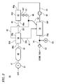
- the above-described ozone generation device 36 includes a compressor 37 that compresses air, a dryer 38 that dries the air compressed by this compressor 37, and an ozone generator 39 that converts the air dried by this dryer 38 into ozone ( Figs. 1 and 2 ).
- the above-described compressor 37 is configured so as to be driven by a battery having a direct current voltage of 24 V. While the compressor is driven by the battery having the direct current voltage of 24 V in this embodiment, the compressor may be driven by a crankshaft of the engine or it may be driven by a battery having a direct current voltage of in a range of from 200 to 300 V so long as a hybrid vehicle is concerned.
- the above-described dryer 38 is configured so that a water vapor separation membrane 38a ( Fig. 4 ) which water vapor (moisture) easily permeates through and which air hardly permeates through is housed in a cylindrical housing 38d.
- This water vapor separation membrane 38a is, for example, formed by bundling aromatic polyimide asymmetric hollow fibers 38b having 100 ⁇ m in membrane thickness, 500 ⁇ m in outer diameter, and 450 mm in length.
- the water vapor separation membrane 38a extends in the longitudinal direction of the housing 38d and housed in the housing 38d ( Fig. 2 ).
- the above-described hollow fibers 38b are formed with through-holes 38c in the center thereof and have an asymmetric sparse-dense structure in the membrane thickness direction.
- the above-described through-hole 24c is, for example, formed so as to have 300 ⁇ m in inner diameter.
- an air inlet 38e that introduces the air compressed by the compressor 37 is formed on one end surface, in the longitudinal direction, of the housing 38d.
- An air outlet 38f that discharges the air dried by the dryer 38 is formed on the other end surface, in the longitudinal direction, of the housing 38d.
- the air inlet 38e is connected to one end of each hollow fiber 38b of the water vapor separation membrane 38a, and the air outlet 38f is connected to the other end of each hollow fiber 38b of the water vapor separation membrane 38a, whereby the air inlet 38e and the air outlet 38f are communicated with and connected to the through-hole 38c of each hollow fiber 38b.
- a purge gas inlet 38g that introduces a nitrogen-rich gas which will described later as a purge gas and a purge gas outlet 38h that discharges the nitrogen-rich gas as the purge gas together with a water vapor (moisture) are formed on an outer peripheral surface of the housing 38d. Then, the nitrogen-rich gas introduced from the purge gas inlet 38g passes through outer peripheral surfaces of the hollow fibers 38b of the water vapor separation membrane 38a and is discharged from the purge gas outlet 38h.
- the water vapor in the air flowing through the through-hole 38c permeates from an inner surface side of the membrane of the hollow fiber 38b with a higher water vapor partial pressure into an outer surface side of the membrane of the hollow fiber 38b with a lower water vapor partial pressure while utilizing a difference in water vapor partial pressure between on the inner surface side and the outer surface side of the membrane of the hollow fiber 38b as a driving force. Therefore, the water vapor in the air flowing through the through-hole 38c of the hollow fiber 38b decreases, and the dry air is discharged from the air outlet 38f.
- a silent discharge type ozone generator is used as the ozone generator 39 ( Fig. 2 ).
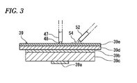
- this ozone generator 39 has a discharge electrode 39a and a ground electrode 39b which are arranged in parallel to each other while being separated with a predetermined interval; a dielectric 39c made of a ceramic such as Al 2 O 3 , etc., which is interposed between these electrodes 39a, 39b; a plate-like ceramic cover 39d that covers a surface of the ground electrode 39b; and a moisture absorbing member 39e provided on a surface of this ceramic cover 39d.
- a high-frequency high voltage is applied between the above-described pair of the electrodes 39a and 39b by a high-voltage power source apparatus (not shown), a plasma discharge is generated between the discharge electrode 39a and the dielectric 39c, and a part of oxygen contained in the air is converted into ozone by means of this plasma discharge.
- the ceramic cover 39d is formed of aluminum nitride or silicon carbide with good heat conductivity, or the like.
- the moisture absorbing member 39e is formed of a ceramic such as porous zeolite capable of absorbing drain water 48 which will be described later, or the like. This moisture absorbing member 39e is formed in a porous state by coating the surface of the ceramic cover with a slurry containing zeolite powder or the like, followed by baking.
- an air separator 40 is provided between the dryer 38 and the ozone generator 39 ( Fig. 2 ).
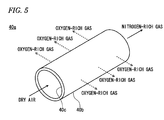
- This air separator 40 is configured so that an oxygen enrichment membrane 40a ( Fig. 5 ) having such properties that an oxygen gas more easily permeates through it than a nitrogen gas in the air is housed in a cylindrical housing 40d.
- the oxygen enrichment membrane 40a is configured so as to separate the air dried by the dryer 38 into an oxygen-rich gas having a high oxygen concentration and a nitrogen-rich gas having a high nitrogen concentration.
- the oxygen enrichment membrane 40a is formed by bundling hollow fibers 40b, each of which is made of a polymer that selectively allows an oxygen gas to more permeates therethrough than a nitrogen gas, is formed with a through-hole 40c in the center thereof, extends in a longitudinal direction of the housing 40d, and is housed in the housing 40d.
- the hollow fibers 40b constituting the oxygen enrichment membrane 40a are preferably formed of a glassy polymer having a large degree of separation between an oxygen gas and a nitrogen gas, and more preferably formed of a polyimide having an especially large degree of separation between an oxygen gas and a nitrogen gas and having excellent mechanical strength, heat resistance, and durability, and the like.
- the membrane of the hollow fiber 40b constituting the oxygen enrichment membrane 40a may be a homogenous membrane having a uniform density in the membrane thickness direction, or a composite membrane that is formed so that its density in the membrane thickness direction is non-uniform by inserting plural hollow fibers having different inner diameters, outer diameters, and densities may also be used.
- a dry air inlet 40e that introduces the air dried by the dryer 38 is formed on one end surface of the housing 40d, which houses the oxygen enrichment membrane 40a.
- a nitrogen-rich gas outlet 40f that discharges the nitrogen-rich gas separated by the air separator 40 is formed on the other end surface of the housing 40d ( Fig. 2 ).
- the dry air inlet 40e is connected to one end of each hollow fiber 40b of the oxygen enrichment membrane 40a, and the nitrogen-rich gas outlet 40f is connected to the other end of each hollow fiber 40b of the oxygen enrichment membrane 40a, whereby the dry air inlet 40e and the nitrogen-rich gas outlet 40f are communicated with and connected to the through-hole 40c of each hollow fiber 40b.
- an oxygen-rich gas outlet 40g that discharges the oxygen-rich gas is formed on the outer peripheral surface of the housing 40d, which houses the oxygen enrichment membrane 40a.
- the oxygen-rich gas whose oxygen concentration has become high upon passing through the membrane of the hollow fibers 40b of the oxygen enrichment membrane 40a is discharged from the oxygen-rich gas outlet 40g.
- the membrane of the hollow fibers 40b causes thermal vibration to form gaps through which the gas passes, and therefore, oxygen molecules and nitrogen molecules in the air are captured into the above-described gaps.
- the thickness of the oxygen enrichment membrane 40a is formed relatively thin, and the rate of the oxygen molecules to permeate through the membrane of the hollow fibers 40b is about 2.5 times as larger as the rate of the nitrogen molecules to permeate through the membrane of the hollow fibers 40b.
- the oxygen molecules rapidly permeate from the inner surface side of the membrane of the hollow fibers 40b having the high partial pressure into the outer surface side of the membrane of the hollow fibers 40b having the low partial pressure.
- the oxygen concentration on the outer surface side of the membrane of the hollow fibers 40b becomes high, whereas the oxygen concentration on the inner surface side of the membrane of the hollow fibers 40b becomes low.
- the oxygen-rich gas is generated by passage of the air through the oxygen enrichment membrane 40a, and the nitrogen-rich gas is generated by going straight of the air without passing through the oxygen enrichment membrane 40a.
- the gaps formed in the membrane of the hollow fibers 40b by means of the above-described thermal vibration is about 5 nm.
- the ejection port of the compressor 37 is connected to the air inlet 38e of the dryer 38 by a first supply pipe 41, and the air outlet 38f of the dryer 38 is connected to the dry air inlet 40e of the air separator 40 by a second supply pipe 42 ( Fig. 2 ).
- the oxygen-rich gas outlet 40g of the air separator 40 is connected to the oxygen-rich gas inlet 39f of the ozone generator 39 by a third supply pipe 43, and one end of a fourth supply pipe 44 is connected to the ozone outlet 39g of the ozone generator 39.
- the nitrogen-rich gas outlet 40f of the air separator 40 is connected to the purge gas inlet 38g of the dryer 38 by a purge pipe 46, and one end of a drain pipe 47 is connected to the purge gas discharge pipe 38h of the dryer 38.
- the other end of this drain pipe 47 is provided so as to face the surface of the ozone generator 39, namely, the surface of the moisture absorbing member 39e, and the drain water 48 which is the moisture discharged from the dryer 38 goes through the drain pipe 47 and is dropped onto the moisture absorbing member 39e ( Figs. 2 and 3 ).
- an air tank 49 that stores the air compressed by the compressor 37 is provided in the first supply pipe 41, and a gas flow rate regulation valve 51 that regulates the flow rate of the nitrogen-rich gas passing through the purge pipe 46 is provided in the purge pipe 46 ( Fig. 2 ).
- the above-described air tank 49 is provided to supply a sufficient amount of air into the air separator 40 and to relieve a pressure change of air even if the flow rates of the oxygen-rich gas and the nitrogen-rich gas are abruptly changed.
- one end of a branch pipe 52 is connected to the purge pipe 46 on the nitrogen-rich gas downstream side of the gas flow rate regulation valve 51, and the other end of this branch pipe 52 is provided so as to face the surface of the ozone generator 39, namely, the surface of the moisture absorbing member 39e ( Figs. 2 and 3 ).
- a part of the nitrogen-rich gas separated by the air separator 40 goes through the purge pipe 46 and is supplied from the purge gas inlet 38g into the dryer 38, and the remainder (most) of the nitrogen-rich gas separated by the air separator 40 goes through the purge pipe 46 and the branch pipe 52 and is injected onto the surface of the moisture absorbing member 39e.
- a flow rate ratio of the nitrogen-rich gas which is supplied into the dryer 38 to the nitrogen-rich gas which is injected onto the surface of the moisture absorbing member 39e is set to be about 1:9.
- the nitrogen-rich gas which is supplied from the purge gas inlet 38g into the dryer 38 is used merely to push out the moisture (drain water) within the dryer 38, and therefore, a small amount, to the extent of 10% of the all nitrogen-rich gas, is enough for such use.
- examples of a method of setting the flow rate ratio of the nitrogen-rich gas which is supplied into the dryer 38 to the nitrogen-rich gas which is injected onto the surface of the moisture absorbing member 39e is set to be about 1:9 include a method of setting a inner diameter ratio between the purge pipe 46 and the branch pipe 52 on the nitrogen-rich gas downstream side of a connection part between the purge pipe 46 and the branch pipe 52 to be a predetermined ratio, a method of providing a throttle part in the purge pipe 46 on the nitrogen-rich gas downstream side of a connection part between the purge pipe 46 and the branch pipe 52; and the like.
- a reference sign 53 indicates a check valve provided in the fourth supply pipe 44.
- This check valve 53 allows ozone to flow from the ozone generator 39 into the ozone injection nozzle 14 and inhibits ozone from flowing from the ozone injection nozzle 14 into the ozone generator 39.
- a reference sign 54 indicates a nitrogen-rich gas injected from the other end of the branch pipe 52.
- a casing 56 is provided in the exhaust pipe 12 on the exhaust gas upstream side of the ozone injection nozzle 14, and the oxidation catalyst 13 and a particulate filter 57 are housed in this casing 56 in this order from the exhaust gas upstream side.
- the oxidation catalyst 13 is a monolith catalyst and is configured by coating a cordierite honeycomb carrier with a noble metal catalyst such as platinum zeolite, platinum alumina, platinum-palladium alumina, or the like.
- the oxidation catalyst 13 made of platinum zeolite is configured by coating a honeycomb carrier with a slurry containing a zeolite powder having been ion-exchanged with platinum.
- the oxidation catalyst 13 made of platinum alumina is configured by coating a honeycomb carrier with a slurry containing a ⁇ -alumina powder or ⁇ -alumina powder having platinum supported thereon.
- the oxidation catalyst 13 made of platinum-palladium alumina is configured by coating a honeycomb carrier with a slurry containing a ⁇ -alumina powder or ⁇ -alumina powder having platinum and palladium which are supported thereon.
- the particulate filter 57 has a polygonal shape in section which is partitioned by porous partition made of a ceramic such as a cordierite.
- This filter 57 is configured by alternately sealing inlet parts and outlet parts of through-holes, which are mutually adjoining and which are formed by the partitions in parallel to each other, with sealing members.
- This filter 57 at the time when the exhaust gas of the engine 11 introduced from the inlet parts of the filter 57 passes through the porous partitions, particulates contained in this exhaust gas are trapped and discharged from the outlet parts.
- the above-described exhaust gas purifier is further provided with an air flow sensor 58 that detects an air intake amount of the engine 11; a NOx sensor 59 that detects a NOx concentration in the exhaust pipe 12, which is provided in the exhaust pipe 12 on the upstream side of the ozone injection nozzle 14; a first temperature sensor 61 that detects an inlet temperature of the selective reduction catalyst 17; and a second temperature sensor 72 that detects an inlet temperature of the oxidation catalyst 13.
- the air flow sensor 58 is provided in an inlet of the air intake pipe 19, and the NOx sensor 59 is provided in the exhaust pipe 12 between the turbine housing 22b and the oxidation catalyst 13.
- the first temperature sensor 61 is located on the exhaust gas upstream side of the selective reduction catalyst 17 and is provided in the casing 23, which houses the selective reduction catalyst 17
- the second temperature sensor 72 is located on the exhaust gas upstream side of the oxidation catalyst 13 and is provided in the casing 56, which houses the oxidation catalyst 13 and the particulate filter 57.
- the above-described ozone generation device 36 further includes a flow rate sensor 62 that detects the flow rate of the air dried by the dryer 38; and an ozone concentration sensor 63 that is provided between the ozone generator 39 and the ozone injection nozzle 14 and that detects a concentration of ozone generated in the ozone generator 39.
- the flow rate sensor 62 is provided in the third supply pipe 43 between the air separator 40 and the ozone generator 39, and the ozone concentration sensor 63 is provided in the fourth supply pipe 44 between the ozone generator 39 and the check valve 53.
- an ultraviolet type sensor having durability against high-concentration ozone is used for the ozone concentration sensor 63 rather than a semiconductor type sensor which does not have durability against high-concentration ozone yet.
- This ozone concentration sensor 63 of the ultraviolet type is a sensor that utilizes such properties that ozone absorbs a wavelength in the vicinity of 254 nm.
- a load of the engine 11 namely, a fuel injection quantity
- a revolution speed of the engine 11 is detected by a rotation sensor 66.
- Respective detection outputs of the above-described air flow sensor 58, NOx sensor 59, first temperature sensor 61, second temperature sensor 72, flow rate sensor 62, ozone concentration sensor 63, load sensor 64, and rotation sensor 66 are connected to a control input of a controller 67, and control outputs of the controller 67 is connected to the compressor 37, the ozone generator 39 (high-voltage power source apparatus), the fluid pump 29, the fluid on-off valve 33, and the gas flow rate regulation valve 51, respectively.
- a memory 68 is provided in the controller 67. As shown in Fig.
- Xa K 1 ⁇ Cn ⁇ (Qn + Dn) (K 1 : constant)
- Xr K 2 ⁇ Co ⁇ Qo (K 2 : constant)
- the memory 68 stores, as a map, a change in flow rate ratio of NO to NO 2 in the exhaust gas with respect to a NOx concentration in the exhaust gas, an exhaust gas temperature at the inlet of the oxidation catalyst 13, and the exhaust gas flow rate which is computed from the air amount Qn detected by the air flow sensor 58 and the engine load (fuel injection quantity Dn into the engine 11) detected by the load sensor 64.
- the ozone generated in the above-described ozone generator 39 is supplied into the ozone injection nozzle 14 and injected (supplied) from the ozone injection nozzle 14 into the exhaust pipe 12.
- the reason why the ozone is supplied into the exhaust pipe 12 is to convert, by ozone, a part of NO in the exhaust gas into NO 2 having high reactivity, to thereby make the flow rate ratio of NO to NO 2 in the exhaust gas, which is introduced into the selective reduction catalyst 17, be close to a ratio of 1:1 at which a reduction reaction of NO and NO 2 to N 2 by the urea-based fluid 24 in the selective reduction catalyst 17 proceeds most rapidly.
- the controller 67 determines the flow rate ratio of NO to NO 2 in the exhaust gas discharged from the engine 11 based on the NOx concentration in the exhaust gas, which is detected by the NOx sensor 59, the exhaust gas temperature at the inlet of the oxidation catalyst, which is detected by the second temperature sensor 72, and the exhaust gas flow rate which is computed from the air amount Qn detected by the air flow sensor 58 and the engine load (fuel injection quantity Dn into the engine 11) detected by the load sensor 64. Then, the controller 67 controls the compressor 37 and the ozone generator 39 (high-voltage power source apparatus) so that the flow rate ratio of NO to NO 2 to be introduced into the selective reduction catalyst 17 is close to 1:1, to thereby generate an appropriate amount of ozone.
- the urea-based fluid 24 goes through the fluid supply pipe 27 and is intermittently injected (supplied) into the exhaust pipe 12.
- the reason why the urea-based fluid 24 is supplied into the exhaust pipe 12 is for the urea-based fluid 24 to function as a reducing agent for reduction of NOx (NO and NO 2 ) in the exhaust gas to N 2 .
- a specific chemical reaction in the selective reduction catalyst 17 is expressed by the following formulae (2) and (3) in the case where the urea-based fluid 24 is urea water and also expressed by the following formula (4) in the case where the urea-based fluid 24 is an ammonia gas, respectively.
- the above-described formula (2) represents a chemical reaction formula in which hydrolysis of the urea water (urea-based fluid 24) to an ammonia gas proceeds although its amount is relatively small because the exhaust gas temperature at the inlet of the selective reduction catalyst 17 is relatively is lower than 220 °C and is relatively low.
- the above-described formula (3) represents a chemical reaction formula in which NO and NO 2 in the exhaust gas react with the ammonia gas hydrolyzed from the above-described urea water with the aid of the selective reduction catalyst 17 and NO and NO 2 are reduced to N 2 .
- the above-described formula (4) represents a chemical reaction formula in which NO and NO 2 in the exhaust gas react with the ammonia gas (urea-based fluid 24) with the aid of the selective reduction catalyst 17, and NO and NO 2 are reduced to N 2 .
- the use of the ammonia gas allows the reduction reaction of NO and NO 2 to N 2 to proceed more rapidly, and therefore, it is preferable to use the ammonia gas as the urea-based fluid 24.
- the controller 67 stops the compressor 37 and the ozone generator 39 (high-voltage power source apparatus) of the ozone generation device 36 and also closes the gas flow rate regulation valve 51 based on the detection output of the first temperature sensor 61.
- the controller 67 stops the compressor 37 and the ozone generator 39 (high-voltage power source apparatus) of the ozone generation device 36 and also closes the gas flow rate regulation valve 51 based on the detection output of the first temperature sensor 61.
- the air is compressed and stored in the air tank 49.
- the dryer 38 removes the moisture of the air to thereby dray the air, and this dried air is separated, by the air separator 40, into an oxygen-rich gas having a high oxygen concentration and a nitrogen-rich gas having a high nitrogen concentration.
- the oxygen-rich gas separated by the sir separator 40 is supplied into the ozone generator 39, a part of oxygen in the oxygen-rich gas is converted into ozone by the ozone generator 39, and this ozone goes through the fourth supply pipe 44 and is supplied into the ozone injection nozzle 14.
- a part of the nitrogen-rich gas 54 separated by the air separator 40 goes through the purge pipe 46 and is supplied from the purge gas inlet 38g into the dryer 38, and the remainder (most) of the nitrogen-rich gas 54 separated by the air separator 40 goes through the purge pipe 46 and the branch pipe 52 and is injected onto the surface of the moisture absorbing member 39e of the ozone generator 39.
- the drain water 48 which is the moisture separated by the dryer 38 is pushed out, goes through the drain pipe 47, and is dropped onto the surface of the moisture absorbing member 39e of the ozone generator 39. At that time, the drain water 48 soaks into the porous moisture absorbing member 39e and spreads over a relatively wide area.
- the drain water 48 When the nitrogen-rich gas 54 is sprayed onto the surface of the moisture absorption member 39e in this state, the drain water 48 rapidly vaporizes, and therefore, the ozone generator 39 is cooled by this latent heat of vaporization. In this way, since not only both the nitrogen-rich gas 54 separated by the air separator 40 and the drain water 48 discharged from the dryer 38 are used, but also the drain water 48 is caused to soak into the porous moisture absorbing member 39e to cool the ozone generator 39 which is easy to generate heat due to internal discharge, the ozone generator 39 can be efficiently cooled.
- the dryer 38 since the dryer 38 is regenerated using the nitrogen-rich gas 54, which is unnecessary for generating ozone, without using an oxygen-rich gas which is necessary for generating ozone, the dryer 38 can be efficiently regenerated. Also, since the air compressed by the compressor 37 may not be used directly for the purpose of regenerating the dryer 38, the consumption amount of the air compressed by the compressor 37 can be suppressed. As a result, since the ejection capacity of the compressor 37 can be decreased, it is possible to contemplate to achieve downsizing of the compressor 37. Furthermore, if the oxygen-rich gas is increased, the moisture amount in the air which is to be removed by the dryer 38 also increases.
- the opening degree of the gas flow rate regulation valve 51 is made large, the nitrogen-rich gas 54 which is separated by the air separator 40 also increases. Therefore, the increased moisture within the dryer 38 can be removed by this increased nitrogen-rich gas 54. As a result, even if the oxygen-rich gas increases or decreases, the nitrogen-rich gas 54 also increases or decreases in accordance with this increase or decrease of the oxygen-rich gas, and therefore, the dryer 38 can be efficiently regenerated.
- the increased moisture (drain water 48) within the above-described dryer 38 goes through the drain pipe 47, is dropped onto the surface of the moisture absorption member 39e of the ozone generator 39, and is used for cooling of the ozone generator 39.
- Fig. 8 shows a second embodiment of the present invention.
- a nitrogen injection nozzle 81 is connected to a tip end of the branch pipe 52.
- the nitrogen injection nozzle 81 is provided so as to have a predetermined gap from the surface of the ozone generator 39, namely the surface of the moisture absorption member 39e and to extend in parallel to the surface of the moisture absorption member 39e.
- plural injection ports 81a facing the surface of the moisture absorption member 39e are formed in predetermined intervals in a longitudinal direction of the nitrogen injection nozzle 81.
- Te second embodiment has the same configuration as the first embodiment except the above.
- the nitrogen-rich gas 54 separated by the air separator goes through the purge pipe and the branch pipe 52 and is injected substantially uniformly from the plural injection ports 81a of the nitrogen injection nozzle 81 onto the surface of the moisture absorption member 39e of the ozone generator 39. Therefore, the ozone generator 39 can be cooled more efficiently as compared with the first embodiment.
- the operations other than those described above are substantially the same as the operations of the first embodiment, and therefore, redundant description thereon will be omitted.
- the exhaust gas purifier of the present invention is applied to the diesel engine.
- the exhaust gas purifier of the present invention may also be applied to a gasoline engine.
- the exhaust gas purifier of the present invention is applied to the diesel engine having the turbo supercharger.
- the exhaust gas purifier of the present invention may also be applied to a natural aspirated diesel engine or a natural aspirated gasoline engine.
- the silent discharge type is used as the ozone generator.
- the air tank is provided between the compressor and the dryer.
- the fluid pressure is regulated by the fluid pressure regulation valve, which is a three way valve.
- the fluid pressure may be regulated by adjusting an opening/closing time of the fluid on-off valve and the presence or absence of driving of the fluid pump without using the fluid pressure regulation valve.
- the air is supplied to the ozone generator.
- an air-containing exhaust gas of the engine may also be supplied.
- the ceramic cover of the ozone generator is formed in a plate-like shape.
- plural fins may be provided on the surface of the plate-like ceramic cover in predetermined intervals to rise up from the surface of the plate-like ceramic cover. In that case, a cooling performance of the ozone generator is enhanced.
- the moisture absorption member is formed in a porous state by baking after being coated on the surfaces of the ceramic cover and the fins.
- the exhaust gas purifier of the present invention can be utilized for decreasing nitrogen oxides (NOx) contained in an exhaust gas of an engine by using ozone and a urea-based fluid, to thereby purify the exhaust gas.
- NOx nitrogen oxides
Landscapes
- Chemical & Material Sciences (AREA)
- Engineering & Computer Science (AREA)
- Chemical Kinetics & Catalysis (AREA)
- Combustion & Propulsion (AREA)
- General Chemical & Material Sciences (AREA)
- Analytical Chemistry (AREA)
- Health & Medical Sciences (AREA)
- Oil, Petroleum & Natural Gas (AREA)
- Biomedical Technology (AREA)
- Environmental & Geological Engineering (AREA)
- Organic Chemistry (AREA)
- Mechanical Engineering (AREA)
- General Engineering & Computer Science (AREA)
- Inorganic Chemistry (AREA)
- Toxicology (AREA)
- Exhaust Gas After Treatment (AREA)
- Oxygen, Ozone, And Oxides In General (AREA)
Abstract
Description
- The present invention relates to an apparatus for decreasing nitrogen oxides (NOx) contained in an exhaust gas of an engine, to thereby purify the exhaust gas.
- Conventionally, there is disclosed an exhaust gas aftertreatment system in which exhaust gas discharged from an internal combustion engine flows through an exhaust pipe; a muffler for reducing exhaust noise that is created when the exhaust gas is released to the atmosphere is connected to the exhaust pipe; a purifier for purifying the exhaust gas is provided in the exhaust pipe; ozone is generated by an ozone generation reactor; the ozone generation reactor and the exhaust pipe are connected to each other on an upstream side of the purifier in a direction in which the exhaust gas flows by an ozone supply pipe; and the ozone generated by the ozone generation reactor is supplied to the inside of the exhaust pipe via the ozone supply pipe (see, for example, Patent Literature 1). In this exhaust gas aftertreatment system, an amount of ozone is detected by an ozone sensor, and this ozone sensor is disposed in at least one of the inside of the ozone supply pipe and immediately before the muffler. Also, the ozone generation reactor is provided with a generation section having a pair of electrodes in the inside thereof, a power source section for applying a high voltage between the electrodes, and an air pump for supplying air into the inside of the generation section. In addition, the ozone supply pipe is provided with an on-off valve which switches communication and interruption between the ozone supply pipe and the exhaust pipe. Furthermore, the power source section, the air pump, and the on-off valve are electrically connected to an ECU (Engine Control Unit), and the exhaust gas aftertreatment system is configured so that their operations are controlled based on an output from ECU.
- In the thus configured exhaust gas aftertreatment system, in the case where the ozone sensor is disposed in the inside of the ozone supply pipe, since the ozone supply pipe is not a passage through which the exhaust gas flows, it does not become a high temperature state as in the inside of the exhaust pipe. In consequence, it is possible to use, as the ozone sensor, a semiconductor ozone sensor which is low in heat resistance but is capable of detecting a minute amount of ozone, and the generation amount of ozone by the ozone generation reactor can be accurately detected. Meanwhile, in the case where the ozone sensor is disposed immediately before the muffler, in general, the exhaust gas which has passed through the purifier is cooled during a period in which it flows inside the exhaust pipe, and before the exhaust gas reaches the muffler, it becomes a temperature state such that it is possible to use a semiconductor ozone sensor. In consequence, it is possible to use a semiconductor ozone sensor as the ozone sensor, and the amount of ozone remaining in an unreacted state is accurately detected. Therefore, it has become possible to accurately detect the amount of ozone.
- Meanwhile, there is disclosed an ozone generation device in which a high-voltage electrode is provided on one of surfaces of a dielectric; an ground electrode is arranged in parallel via a gap part on the other surface of the dielectric; these electrodes are housed in an ozone generation vessel; and a voltage is applied between the high-voltage electrode and the ground electrode to generate ozone in a raw material gas which has been allowed to flow into the gap part (see, for example, Patent Literature 2). This ozone generation device is configured so that a nitrogen enrichment apparatus concentrates nitrogen in compressed air and removes it, the residual gas after nitrogen has been removed by this nitrogen enrichment apparatus and the above-described compressed air are mixed, and this mixed gas is introduced as the raw material gas into the ozone generation vessel. Also, an oxygen concentration of the raw material gas to be introduced into the ozone generation vessel is detected by an oxygen concentration meter, and a concentration of ozone generated in the ozone generation vessel is detected by an ozone concentration meter. Furthermore, a control means controls the oxygen concentration of the raw material gas to be introduced into the ozone generation vessel, a gas flow rate, and an amount of input power based on respective detection outputs of the oxygen concentration meter and the ozone concentration meter. It is noted that a membrane separation type apparatus is used as the nitrogen enrichment apparatus.
- In the thus configured ozone generation device, the nitrogen-concentrated gas (nitrogen-rich gas) is released and removed by the nitrogen enrichment apparatus, and therefore, a large amount of oxygen is contained in the residual gas. Then, the control means is controlled based on the detection output of each concentration meter. Therefore, when the ozone concentration is given as an instruction value, not only the raw material gas is controlled to have optimum oxygen concentration and gas flow rate, but also the amount of input power to the ozone generation device is controlled to be an optimum amount of input power. As a result, the above-described ozone generation device is able to avoid waste of oxygen, is low in costs, and enables the operation efficiency to increase. Also, since a part of the compressed air is enriched by the nitrogen enrichment apparatus, oxygen having a desired high concentration is obtained without increase of the amount of compressed air. As a result, a loss in a compressor that compresses air can be decreased.
-
- Patent Literature 1:
JP 2012-26331 A Fig. 1 ) - Patent Literature 2:
JP Hei.07-277708 A Figs. 1 and2 ) - In the exhaust gas aftertreatment system disclosed in the above-described conventional Patent Literature 1, since the air pump and the ozone generator are connected directly with each other, the flow rate of air can be computed based on a rotation speed of the air pump or the like even without detection of a flow rate of air immediately before the air flows into the ozone generator. However, in the exhaust gas aftertreatment system disclosed in the above-described conventional Patent Literature 1, a relatively large amount of moisture is contained in air which is forcedly supplied into the air pump. Therefore, there was caused such an inconvenience that the ozone is not stably generated by the ozone generator, or a product is generated, so that the generation efficiency of ozone is low. For that reason, if a dehumidifier for removing the moisture in air is provided between the air pump and the ozone generator, the pressure of air from the air pump is increased by the dehumidifier. Therefore, the flow rate of air immediately before the air flows into the ozone generator cannot be accurately detected only based on the rotation speed of the air pump. Thus, there was a problem such that the supply amount of ozone relative to the NOx amount in the exhaust gas is excessively large or excessively small. Meanwhile, in the ozone generation device disclosed in the above-described conventional Patent Literature 2, since the gas (nitrogen-rich gas) in which nitrogen is concentrated by the membrane separation type nitrogen enrichment apparatus is released into the air as it is and removed, it was not contemplated to effectively utilize the gas (nitrogen-rich gas) in which nitrogen is concentrated. Also, the ozone generation device disclosed in the above-described conventional Patent Literature 2 had such a characteristic that generation of heat is easy to take place due to internal discharge.
- A first object of the present invention is to provide an exhaust gas purifier capable of efficiently generating ozone by an ozone generator by removing moisture in air, which is compressed by a compressor, by means of a dehumidifier and capable of supplying just enough ozone in amount, which corresponds to an NOx amount in exhaust gas and a flow rate ratio of NO to NO2, into an exhaust pipe by accurate detection of a flow rate of air immediately before the air flows into the ozone generator by means of a flow rate sensor. A second object of the present invention is to provide an exhaust gas purifier capable of efficiently decreasing NOx even when an exhaust gas temperature is low and capable of efficiently decreasing NOx over almost all exhaust gas temperature range. A third object of the present invention is to provide an exhaust gas purifier capable of efficiently cooling an ozone generator by means of either one or both of a nitrogen-rich gas separated by an air separator and drain water discharged from a dryer. A fourth object of the present invention is to provide an exhaust gas purifier capable of enhancing regeneration efficiency of a dryer.
- According to a first aspect of the present invention, as shown in
Figs. 1 and2 , an exhaust gas purifier in which anoxidation catalyst 13, anozone injection nozzle 14, a urea-basedfluid injection nozzle 16, and aselective reduction catalyst 17 are arranged in anexhaust pipe 12 of anengine 11 in this order towards an outlet of theexhaust pipe 12, the exhaust gas purifier including anair flow sensor 58 that detects an air intake amount of theengine 11, aNOx sensor 59 that is provided in theexhaust pipe 12 on an upstream side of theozone injection nozzle 14 and that detects a NOx concentration in theexhaust pipe 12, afirst temperature sensor 61 that detects an inlet temperature of theselective reduction catalyst 17, and asecond temperature sensor 72 that detects an inlet temperature of theoxidation catalyst 13, the exhaust gas purifier is characterized in that theozone injection nozzle 14 is connected to anozone generation device 36, theozone generation device 36 includes acompressor 37 that compresses air, adryer 38 that dries the air compressed by thecompressor 37, aflow rate sensor 62 that detects a flow rate of the air dried by thedryer 38, anozone generator 39 that converts the air detected by theflow rate sensor 62 into ozone, and anozone concentration sensor 63 that is provided between theozone generator 39 and theozone injection nozzle 14 and that detects a concentration of the ozone generated by theozone generator 39, a load of theengine 11 is detected by aload sensor 64, and acontroller 67 controls an air amount by thecompressor 37 and an amount of ozone generated by theozone generator 39 based on respective detection outputs of theair flow sensor 58, theNOx sensor 59, thefirst temperature sensor 61, thesecond temperature sensor 72, theflow rate sensor 62, theozone concentration sensor 63, and theload sensor 64. - According to a second aspect of the present invention, in the invention based on the first aspect, as further shown in
Figs. 2 and3 , theozone generation device 36 further includes anair separator 40 that is provided between thedryer 38 and theozone generator 39 and that separates the air dried by thedryer 38 into an oxygen-rich gas having a high oxygen concentration and a nitrogen-rich gas 54 having a high nitrogen concentration, a part of oxygen in the oxygen-rich gas separated by theair separator 40 is introduced into theozone generator 39 and converted into ozone by theozone generator 39, and moisture within thedryer 38 is removed by the nitrogen-rich gas 54 separated by theair separator 40, to regenerate thedryer 38, and theozone generator 39 is cooled by either or both of the nitrogen-rich gas 54 separated by theair separator 40 anddrain water 48 that is the moisture discharged from thedryer 38. - According to a third aspect of the present invention, in the invention based on the second aspect, as further shown in
Fig. 3 , a porousmoisture absorption member 39e that can absorb thedrain water 48 is provided on a surface of theozone generator 39. - According to a fourth aspect of the present invention, in the invention based on the second aspect, as further shown in
Figs. 2 ,3 , and5 , theair separator 40 is configured by anoxygen enrichment membrane 40a, the oxygen-rich gas is generated by passage of the air, which is dried by thedryer 38, through theoxygen enrichment membrane 40a, and the nitrogen-rich gas 54 is generated by going straight of the air, which is dried by thedryer 38, without passing through theoxygen enrichment membrane 40a. - According to a fifth aspect of the present invention, in the invention based on the second aspect, as further shown in
Figs. 2 and3 , the nitrogen-rich gas 54 separated by theair separator 40 goes through apurge pipe 46 and is supplied to thedryer 38, a gas flowrate regulation valve 51 that regulates a flow rate of the nitrogen-rich gas 54, which passes through thepurge pipe 46, is provided in thepurge pipe 46, one end of abranch pipe 52 is connected to thepurge pipe 46 on a nitrogen-rich gas downstream side of the gas flowrate regulation valve 51, and the other end of thebranch pipe 52 is provided to face a surface of theozone generator 39. - In the ozone generation device of the first aspect of the present invention, the controller controls the compressor and the ozone generator based on the respective detection outputs of the air flow sensor, the NOx sensor, the first temperature sensor, the second temperature sensor, the flow rate sensor, the ozone concentration sensor, and the load sensor. Air is compressed by this compressor, dry air obtained by removing the moisture from this air by a dehumidifier is supplied to the ozone generator, and ozone generated in this ozone generator is added to the exhaust pipe. As a result, as compared with the conventional exhaust gas aftertreatment system in which since a relatively large amount of moisture is contained in air which is forcedly supplied into an air pump, ozone is not stably generated by an ozone generator or a product is generated, so that the generation efficiency of ozone is low, according to the present invention, the moisture in the air is removed by the dehumidifier, and therefore, the ozone can be efficiently generated by the ozone generator.
- Also, the controller computes an ozone requirement based on the respective detection outputs of the air flow sensor, the NOx sensor, the second temperature sensor, and the load sensor. On the other hand, the controller computes the ozone generation amount based on the respective detection outputs of the flow rate sensor and the ozone concentration sensor. Then, the controller controls the compressor and the ozone generator so as to coincide with the above-described ozone requirement. As a result, even if a surrounding environment (a surrounding temperature and/or a surrounding humidity) of the ozone generator changes, the ozone in proper quantity that corresponds to a NOx amount in the exhaust gas and a flow rate ratio of NO to NO2 can be supplied into the exhaust pipe, namely just enough ozone in accurate amount following an operation state of the engine can be supplied into the exhaust pipe.
- Furthermore, if the ozone is supplied from the ozone injection nozzle into the exhaust pipe, NO of NOx in the exhaust gas reacts with the ozone to rapidly generate NO2 having high reactivity, and if this NO2 having high reactivity flows into the selective reduction catalyst together with the urea-based fluid supplied from the urea-based fluid injection nozzle into the exhaust pipe, even at a low exhaust gas temperature, NO2 having high reactivity and the urea-based fluid cause a selective reduction reaction to proceed with the aid of the selective reduction catalyst. As a result, even if the exhaust gas temperature is low, NOx can be efficiently decreased. On the other hand, if the exhaust gas temperature becomes a predetermined temperature or higher, the oxidation catalyst oxidizes NO in the exhaust gas to NO2 having high reactivity. Therefore, if this NO2 having high reactivity flows into the selective reduction catalyst together with the urea-based fluid supplied from the urea-based fluid injection nozzle into the exhaust pipe, even at a high exhaust gas temperature, NO2 having high reactivity and the urea-based fluid cause the selective reduction reaction to proceed with the aid of the selective reduction catalyst. As a result, even if the exhaust gas temperature becomes high, NOx can be efficiently decreased. In consequence, NOx can be efficiently decreased over almost all exhaust gas temperature range.
- In the ozone generation device of the second aspect of the present invention, the part of oxygen in the oxygen-rich gas separated by the air separator is introduced into the ozone generator and converted into ozone by the ozone generator, and the moisture within the dryer is removed by the nitrogen-rich gas separated by the air separator to regenerate the dryer. Therefore, the dryer can be efficiently regenerated. That is, since the air compressed by the compressor may not be used directly for the purpose of regenerating the dryer, the consumption amount of the air compressed by the compressor can be suppressed. As a result, since the ejection capacity of the compressor can be decreased, it is possible to achieve downsizing of the compressor. Also, if the oxygen-rich gas increases, the amount of moisture in the air to be removed by the dryer increases. However, the nitrogen-rich gas to be separated by the air separator increases as well. Therefore, the increased moisture within the dryer can be removed by this increased nitrogen-rich gas. As a result, even if the oxygen-rich gas increases or decreases, the nitrogen-rich gas also increases or decreases following the increase or decrease of the oxygen-rich gas. Therefore, the dryer can be efficiently regenerated. Furthermore, the ozone generator is cooled by using either one or both of the nitrogen-rich gas separated by the air separator and the drain water that is the moisture discharged from the dryer. Therefore, the ozone generator can be efficiently cooled.
- In an ozone generation device method of the third aspect of the present invention, the porous moisture absorbing member that can absorb the drain water is provided on the surface of the ozone generator. Therefore, if the drain water is dropped onto the surface of the moisture absorbing member, this drain water soaks into the porous moisture absorbing member and spreads over a relatively wide area, and the ozone generator is cooled with a latent heat when this drain water vaporizes. As a result, when the nitrogen-rich gas is injected onto the surface of the moisture absorbing member in a state where the drain water soaks into the porous moisture absorbing member, the drain water rapidly vaporizes, and therefore, the ozone generator can be more efficiently cooled by this latent heat of vaporization.
- In the ozone generation device of the fourth aspect of the present invention, the air separator is configured by the oxygen enrichment membrane, the oxygen-rich gas is generated by passing of the air, which is dried by the dryer, through the oxygen enrichment membrane, and the nitrogen-rich gas is generated by going straight of the air, which is dried by the dryer, without passing through the oxygen enrichment membrane. Therefore, the oxygen-rich gas and the nitrogen-rich gas can be surely separated from each other by the oxygen enrichment membrane. As a result, by using the air separator having a relatively simple structure, the oxygen-rich gas and the nitrogen-rich gas can be efficiently generated by the oxygen enrichment membrane of this air separator.
- In the ozone generation device of the fifth aspect of the present invention, the gas flow rate regulation valve is provided in the purge pipe, which supplies the nitrogen-rich gas separated by the air separator into the dryer. Therefore, by merely adjusting the flow rate of the nitrogen-rich gas passing through the purge pipe in a state where the compressor is kept at a rated operation, the flow rate of the oxygen-rich gas can be adjusted as well. Also, the branch pipe, one end of which is connected to the purge pipe on the nitrogen-rich gas downstream side of the gas flow rate regulation valve, is provided so that the other end thereof faces the surface of the ozone generator. Therefore, the nitrogen-rich gas separated by the air separator can be efficiently distributed into the dryer and the ozone generator.
-
-
Fig. 1 is a configuration diagram of an exhaust gas purifier showing first embodiment of the present invention. -
Fig. 2 is an air circuit configuration diagram of an ozone generation device provided in the exhaust gas purifier. -
Fig. 3 is a main portion section configuration diagram showing a state where an ozone generator of the ozone generation device is cooled with nitrogen-rich gas and drain water. -
Fig. 4 is a main portion enlarged section view of a hollow fiber constituting a water vapor separation membrane of a dryer. -
Fig. 5 is a main portion enlarged section view of a hollow fiber constituting an oxygen enrichment membrane of an air separator. -
Fig. 6 is a flowchart showing a method of controlling a generation amount of ozone. -
Fig. 7 is a flowchart for feeding back a difference between a computed value of an ozone requirement and an actual ozone generation amount, to thereby control the ozone generation amount. -
Fig. 8 is a main portion configuration diagram showing a second embodiment of the present invention and corresponding toFig. 3 . - Next, embodiments of the invention will be described based on the accompanying drawings.
- As shown in
Fig. 1 , an exhaust gas purifier for adiesel engine 11 is configured so that anoxidation catalyst 13, anozone injection nozzle 14, a urea-basedfluid injection nozzle 16, and aselective reduction catalyst 17 are arranged in anexhaust pipe 12 of theengine 11 in this order towards an outlet of thisexhaust pipe 12. Anair intake pipe 19 is connected to an air intake port of thisengine 11 via anair intake manifold 18, and theexhaust pipe 12 is connected to an exhaust port of thisengine 11 via anexhaust manifold 21. Theair intake pipe 19 is provided with acompressor housing 22a of aturbo supercharger 22 and an inter cooler 20 for cooling the intake air compressed by theturbo supercharger 22, and theexhaust pipe 12 is provided with aturbine housing 22b of theturbo supercharger 22. A compressor blade (not shown) is housed in thecompressor housing 22a so as to be rotatable, and a turbine blade (not shown) is housed in theturbine housing 22b so as to be rotatable. The compressor blade and the turbine blade are connected with each other by a shaft (not shown), energy of an exhaust gas discharged from theengine 11 rotates via the shaft the turbine blade and the compressor blade via the shaft, and the intake air within the air intake pipe is compressed by means of rotation of this compressor blade. - The above-described
selective reduction catalyst 17 is housed in acasing 23 having a larger diameter than theexhaust pipe 12. Theselective reduction catalyst 17 is a monolith catalyst and is configured by coating a cordierite honeycomb carrier with zeolite or zirconia. Examples of the zeolite include copper zeolite, iron zeolite, zinc zeolite, cobalt zeolite, and the like. Theselective reduction catalyst 17 made of copper zeolite is configured by coating a honeycomb carrier with a slurry containing zeolite powder having been ion-exchanged with copper. Also, theselective reduction catalyst 17 made of iron zeolite, zinc zeolite, or cobalt zeolite is configured by coating a honeycomb carrier with a slurry containing zeolite powder having been ion-exchanged with iron, zinc, or cobalt, respectively. Furthermore, theselective reduction catalyst 17 made of zirconia is configured by coating a honeycomb carrier with a slurry containing γ-alumina powder or θ-alumina powder having zirconia supported thereon. - Meanwhile, the urea-based
fluid injection nozzle 16 is provided in theexhaust pipe 12 on the exhaust gas upstream side of theselective reduction catalyst 17. This urea-basedfluid injection nozzle 16 is connected to a urea-basedfluid supply device 26 for supplying urea-basedfluid 24 to thisnozzle 16. The urea-basedfluid supply device 26 has afluid supply pipe 27, a tip end of which is connected to the urea-basedfluid injection nozzle 16; afluid tank 28 that is connected to a base end of thisfluid supply pipe 27 and that stores the urea-basedfluid 24; afluid pump 29 for forcedly supplying the urea-basedfluid 24 within thisfluid tank 28 into the urea-basedfluid injection nozzle 16; and a fluid supplyamount regulation valve 31 for regulating a supply amount (injection amount) of the urea-basedfluid 24 which is injected from the urea-basedfluid injection nozzle 16. The above-described urea-basedfluid 24 is any one of ammonia gas, urea water, or mist-like urea, which functions as a reducing agent in theselective reduction catalyst 17, or a mixture of two or more of them. Also, the above-describedfluid pump 29 is provided in thefluid supply pipe 27 between the urea-basedfluid injection nozzle 16 and thefluid tank 28, and the fluid supplyamount regulation valve 31 is provided in thefluid supply pipe 27 between the urea-basedfluid injection nozzle 16 and thefluid pump 29. Furthermore, the fluid supplyamount regulation valve 31 includes a fluidpressure regulation valve 32 that regulates a supply pressure of the urea-basedfluid 24 into the urea-basedfluid injection nozzle 16 and that is provided in thefluid supply pipe 27 and a fluid on-offvalve 33 that opens and closes a base end of the urea-basedfluid injection nozzle 16 and that is provided on the base end of the urea-basedfluid injection nozzle 16. - The fluid
pressure regulation valve 32 has first tothird ports 32a to 32c; thefirst port 32a is connected to an ejection port of thefluid pump 29; thesecond port 32b is connected to the fluid on-offvalve 33; and thethird port 32c is connected to thefluid tank 28 via areturn pipe 34. The urea-basedfluid 24, which is forcedly supplied from thefluid pump 29, flows from thefirst port 32a into the fluidpressure regulation valve 32 and is forcedly supplied from thesecond port 32b into the fluid on-offvalve 33. Also, if a pressure at the fluidpressure regulation valve 32 reaches a predetermined pressure or more, the urea-basedfluid 24 which is forcedly supplied by thefluid pump 29 flows from thefirst port 32a into the fluidpressure regulation valve 32 and then goes through thereturn pipe 34 from thethird port 32c and is returned to thefluid tank 28. - Meanwhile, the
ozone injection nozzle 14 is provided in theexhaust pipe 12 on the exhaust gas upstream side of the urea-based fluid injection nozzle 16 (Fig. 1 ). Thisozone injection nozzle 14 is connected to anozone generation device 36 that generates ozone and that supplies the generated ozone to theozone injection nozzle 14. Thisozone generation device 36 is used to generate ozone which oxidizes NO in the exhaust gas discharged from thediesel engine 11 into NO2. The above-describedozone generation device 36 includes acompressor 37 that compresses air, adryer 38 that dries the air compressed by thiscompressor 37, and anozone generator 39 that converts the air dried by thisdryer 38 into ozone (Figs. 1 and2 ). In this embodiment, the above-describedcompressor 37 is configured so as to be driven by a battery having a direct current voltage of 24 V. While the compressor is driven by the battery having the direct current voltage of 24 V in this embodiment, the compressor may be driven by a crankshaft of the engine or it may be driven by a battery having a direct current voltage of in a range of from 200 to 300 V so long as a hybrid vehicle is concerned. - The above-described
dryer 38 is configured so that a watervapor separation membrane 38a (Fig. 4 ) which water vapor (moisture) easily permeates through and which air hardly permeates through is housed in acylindrical housing 38d. This watervapor separation membrane 38a is, for example, formed by bundling aromatic polyimide asymmetrichollow fibers 38b having 100 µm in membrane thickness, 500µm in outer diameter, and 450 mm in length. The watervapor separation membrane 38a extends in the longitudinal direction of thehousing 38d and housed in thehousing 38d (Fig. 2 ). The above-describedhollow fibers 38b are formed with through-holes 38c in the center thereof and have an asymmetric sparse-dense structure in the membrane thickness direction. The above-described through-hole 24c is, for example, formed so as to have 300 µm in inner diameter. Also, anair inlet 38e that introduces the air compressed by thecompressor 37 is formed on one end surface, in the longitudinal direction, of thehousing 38d. An air outlet 38f that discharges the air dried by thedryer 38 is formed on the other end surface, in the longitudinal direction, of thehousing 38d. Theair inlet 38e is connected to one end of eachhollow fiber 38b of the watervapor separation membrane 38a, and the air outlet 38f is connected to the other end of eachhollow fiber 38b of the watervapor separation membrane 38a, whereby theair inlet 38e and the air outlet 38f are communicated with and connected to the through-hole 38c of eachhollow fiber 38b. Furthermore, apurge gas inlet 38g that introduces a nitrogen-rich gas which will described later as a purge gas and apurge gas outlet 38h that discharges the nitrogen-rich gas as the purge gas together with a water vapor (moisture) are formed on an outer peripheral surface of thehousing 38d. Then, the nitrogen-rich gas introduced from thepurge gas inlet 38g passes through outer peripheral surfaces of thehollow fibers 38b of the watervapor separation membrane 38a and is discharged from thepurge gas outlet 38h. - Here, when the air containing a water vapor (moisture) flows within the through-
hole 38c of eachhollow fiber 38b of the watervapor separation membrane 38a, the water vapor in the air flowing through the through-hole 38c permeates from an inner surface side of the membrane of thehollow fiber 38b with a higher water vapor partial pressure into an outer surface side of the membrane of thehollow fiber 38b with a lower water vapor partial pressure while utilizing a difference in water vapor partial pressure between on the inner surface side and the outer surface side of the membrane of thehollow fiber 38b as a driving force. Therefore, the water vapor in the air flowing through the through-hole 38c of thehollow fiber 38b decreases, and the dry air is discharged from the air outlet 38f. - In this embodiment, a silent discharge type ozone generator is used as the ozone generator 39 (
Fig. 2 ). As shown inFig. 3 in detail, thisozone generator 39 has adischarge electrode 39a and aground electrode 39b which are arranged in parallel to each other while being separated with a predetermined interval; a dielectric 39c made of a ceramic such as Al2O3, etc., which is interposed between theseelectrodes ceramic cover 39d that covers a surface of theground electrode 39b; and amoisture absorbing member 39e provided on a surface of thisceramic cover 39d. A high-frequency high voltage is applied between the above-described pair of theelectrodes discharge electrode 39a and the dielectric 39c, and a part of oxygen contained in the air is converted into ozone by means of this plasma discharge. Also, theceramic cover 39d is formed of aluminum nitride or silicon carbide with good heat conductivity, or the like. Furthermore, themoisture absorbing member 39e is formed of a ceramic such as porous zeolite capable of absorbingdrain water 48 which will be described later, or the like. Thismoisture absorbing member 39e is formed in a porous state by coating the surface of the ceramic cover with a slurry containing zeolite powder or the like, followed by baking. - Meanwhile, an
air separator 40 is provided between thedryer 38 and the ozone generator 39 (Fig. 2 ). Thisair separator 40 is configured so that anoxygen enrichment membrane 40a (Fig. 5 ) having such properties that an oxygen gas more easily permeates through it than a nitrogen gas in the air is housed in acylindrical housing 40d. Theoxygen enrichment membrane 40a is configured so as to separate the air dried by thedryer 38 into an oxygen-rich gas having a high oxygen concentration and a nitrogen-rich gas having a high nitrogen concentration. Specifically, theoxygen enrichment membrane 40a is formed by bundlinghollow fibers 40b, each of which is made of a polymer that selectively allows an oxygen gas to more permeates therethrough than a nitrogen gas, is formed with a through-hole 40c in the center thereof, extends in a longitudinal direction of thehousing 40d, and is housed in thehousing 40d. Also, thehollow fibers 40b constituting theoxygen enrichment membrane 40a are preferably formed of a glassy polymer having a large degree of separation between an oxygen gas and a nitrogen gas, and more preferably formed of a polyimide having an especially large degree of separation between an oxygen gas and a nitrogen gas and having excellent mechanical strength, heat resistance, and durability, and the like. Also, the membrane of thehollow fiber 40b constituting theoxygen enrichment membrane 40a may be a homogenous membrane having a uniform density in the membrane thickness direction, or a composite membrane that is formed so that its density in the membrane thickness direction is non-uniform by inserting plural hollow fibers having different inner diameters, outer diameters, and densities may also be used. However, it is preferable to use an asymmetric membrane having a large permeation rate by having an asymmetric sparse-dense structure in the membrane thickness direction. Furthermore, it is preferable to set the membrane thickness of thehollow fiber 40b in a range of from 10 µm to 500 µm and to set the outer diameter of thehollow fiber 40b in a range of from 50 µm to 2000 µm. - A dry air inlet 40e that introduces the air dried by the
dryer 38 is formed on one end surface of thehousing 40d, which houses theoxygen enrichment membrane 40a. A nitrogen-rich gas outlet 40f that discharges the nitrogen-rich gas separated by theair separator 40 is formed on the other end surface of thehousing 40d (Fig. 2 ). The dry air inlet 40e is connected to one end of eachhollow fiber 40b of theoxygen enrichment membrane 40a, and the nitrogen-rich gas outlet 40f is connected to the other end of eachhollow fiber 40b of theoxygen enrichment membrane 40a, whereby the dry air inlet 40e and the nitrogen-rich gas outlet 40f are communicated with and connected to the through-hole 40c of eachhollow fiber 40b. Also, an oxygen-rich gas outlet 40g that discharges the oxygen-rich gas is formed on the outer peripheral surface of thehousing 40d, which houses theoxygen enrichment membrane 40a. The oxygen-rich gas whose oxygen concentration has become high upon passing through the membrane of thehollow fibers 40b of theoxygen enrichment membrane 40a is discharged from the oxygen-rich gas outlet 40g. - Here, a principle of separating the dried air into the oxygen-rich gas having the high oxygen concentration and the nitrogen-rich gas having the high nitrogen concentration by the
oxygen enrichment membrane 40a will be described. When the dried air flows through the through-hole 40c of eachhollow fiber 40b of theoxygen enrichment membrane 40a, the membrane of thehollow fibers 40b causes thermal vibration to form gaps through which the gas passes, and therefore, oxygen molecules and nitrogen molecules in the air are captured into the above-described gaps. At that time, the thickness of theoxygen enrichment membrane 40a is formed relatively thin, and the rate of the oxygen molecules to permeate through the membrane of thehollow fibers 40b is about 2.5 times as larger as the rate of the nitrogen molecules to permeate through the membrane of thehollow fibers 40b. Therefore, the oxygen molecules rapidly permeate from the inner surface side of the membrane of thehollow fibers 40b having the high partial pressure into the outer surface side of the membrane of thehollow fibers 40b having the low partial pressure. Thereby, the oxygen concentration on the outer surface side of the membrane of thehollow fibers 40b becomes high, whereas the oxygen concentration on the inner surface side of the membrane of thehollow fibers 40b becomes low. As a result, the oxygen-rich gas is generated by passage of the air through theoxygen enrichment membrane 40a, and the nitrogen-rich gas is generated by going straight of the air without passing through theoxygen enrichment membrane 40a. It is noted that the gaps formed in the membrane of thehollow fibers 40b by means of the above-described thermal vibration is about 5 nm. - Meanwhile, the ejection port of the
compressor 37 is connected to theair inlet 38e of thedryer 38 by afirst supply pipe 41, and the air outlet 38f of thedryer 38 is connected to the dry air inlet 40e of theair separator 40 by a second supply pipe 42 (Fig. 2 ). Also, the oxygen-rich gas outlet 40g of theair separator 40 is connected to the oxygen-rich gas inlet 39f of theozone generator 39 by athird supply pipe 43, and one end of afourth supply pipe 44 is connected to theozone outlet 39g of theozone generator 39. Furthermore, the nitrogen-rich gas outlet 40f of theair separator 40 is connected to thepurge gas inlet 38g of thedryer 38 by apurge pipe 46, and one end of adrain pipe 47 is connected to the purgegas discharge pipe 38h of thedryer 38. The other end of thisdrain pipe 47 is provided so as to face the surface of theozone generator 39, namely, the surface of themoisture absorbing member 39e, and thedrain water 48 which is the moisture discharged from thedryer 38 goes through thedrain pipe 47 and is dropped onto themoisture absorbing member 39e (Figs. 2 and3 ). - Meanwhile, an
air tank 49 that stores the air compressed by thecompressor 37 is provided in thefirst supply pipe 41, and a gas flowrate regulation valve 51 that regulates the flow rate of the nitrogen-rich gas passing through thepurge pipe 46 is provided in the purge pipe 46 (Fig. 2 ). The above-describedair tank 49 is provided to supply a sufficient amount of air into theair separator 40 and to relieve a pressure change of air even if the flow rates of the oxygen-rich gas and the nitrogen-rich gas are abruptly changed. Also, one end of abranch pipe 52 is connected to thepurge pipe 46 on the nitrogen-rich gas downstream side of the gas flowrate regulation valve 51, and the other end of thisbranch pipe 52 is provided so as to face the surface of theozone generator 39, namely, the surface of themoisture absorbing member 39e (Figs. 2 and3 ). A part of the nitrogen-rich gas separated by theair separator 40 goes through thepurge pipe 46 and is supplied from thepurge gas inlet 38g into thedryer 38, and the remainder (most) of the nitrogen-rich gas separated by theair separator 40 goes through thepurge pipe 46 and thebranch pipe 52 and is injected onto the surface of themoisture absorbing member 39e. A flow rate ratio of the nitrogen-rich gas which is supplied into thedryer 38 to the nitrogen-rich gas which is injected onto the surface of themoisture absorbing member 39e is set to be about 1:9. Here, the nitrogen-rich gas which is supplied from thepurge gas inlet 38g into thedryer 38 is used merely to push out the moisture (drain water) within thedryer 38, and therefore, a small amount, to the extent of 10% of the all nitrogen-rich gas, is enough for such use. Also, examples of a method of setting the flow rate ratio of the nitrogen-rich gas which is supplied into thedryer 38 to the nitrogen-rich gas which is injected onto the surface of themoisture absorbing member 39e is set to be about 1:9 include a method of setting a inner diameter ratio between thepurge pipe 46 and thebranch pipe 52 on the nitrogen-rich gas downstream side of a connection part between thepurge pipe 46 and thebranch pipe 52 to be a predetermined ratio, a method of providing a throttle part in thepurge pipe 46 on the nitrogen-rich gas downstream side of a connection part between thepurge pipe 46 and thebranch pipe 52; and the like. It is noted that inFig. 2 , areference sign 53 indicates a check valve provided in thefourth supply pipe 44. Thischeck valve 53 allows ozone to flow from theozone generator 39 into theozone injection nozzle 14 and inhibits ozone from flowing from theozone injection nozzle 14 into theozone generator 39. Also, inFig. 3 , areference sign 54 indicates a nitrogen-rich gas injected from the other end of thebranch pipe 52. - Referring back to
Fig. 1 , acasing 56 is provided in theexhaust pipe 12 on the exhaust gas upstream side of theozone injection nozzle 14, and theoxidation catalyst 13 and aparticulate filter 57 are housed in thiscasing 56 in this order from the exhaust gas upstream side. Theoxidation catalyst 13 is a monolith catalyst and is configured by coating a cordierite honeycomb carrier with a noble metal catalyst such as platinum zeolite, platinum alumina, platinum-palladium alumina, or the like. Specifically, theoxidation catalyst 13 made of platinum zeolite is configured by coating a honeycomb carrier with a slurry containing a zeolite powder having been ion-exchanged with platinum. Also, theoxidation catalyst 13 made of platinum alumina is configured by coating a honeycomb carrier with a slurry containing a γ-alumina powder or θ-alumina powder having platinum supported thereon. Furthermore, theoxidation catalyst 13 made of platinum-palladium alumina is configured by coating a honeycomb carrier with a slurry containing a γ-alumina powder or θ-alumina powder having platinum and palladium which are supported thereon. Although illustration is omitted, theparticulate filter 57 has a polygonal shape in section which is partitioned by porous partition made of a ceramic such as a cordierite. Thisfilter 57 is configured by alternately sealing inlet parts and outlet parts of through-holes, which are mutually adjoining and which are formed by the partitions in parallel to each other, with sealing members. In thisfilter 57, at the time when the exhaust gas of theengine 11 introduced from the inlet parts of thefilter 57 passes through the porous partitions, particulates contained in this exhaust gas are trapped and discharged from the outlet parts. - The above-described exhaust gas purifier is further provided with an
air flow sensor 58 that detects an air intake amount of theengine 11; aNOx sensor 59 that detects a NOx concentration in theexhaust pipe 12, which is provided in theexhaust pipe 12 on the upstream side of theozone injection nozzle 14; afirst temperature sensor 61 that detects an inlet temperature of theselective reduction catalyst 17; and asecond temperature sensor 72 that detects an inlet temperature of theoxidation catalyst 13. Theair flow sensor 58 is provided in an inlet of theair intake pipe 19, and theNOx sensor 59 is provided in theexhaust pipe 12 between theturbine housing 22b and theoxidation catalyst 13. Also, thefirst temperature sensor 61 is located on the exhaust gas upstream side of theselective reduction catalyst 17 and is provided in thecasing 23, which houses theselective reduction catalyst 17, and thesecond temperature sensor 72 is located on the exhaust gas upstream side of theoxidation catalyst 13 and is provided in thecasing 56, which houses theoxidation catalyst 13 and theparticulate filter 57. Meanwhile, the above-describedozone generation device 36 further includes aflow rate sensor 62 that detects the flow rate of the air dried by thedryer 38; and anozone concentration sensor 63 that is provided between theozone generator 39 and theozone injection nozzle 14 and that detects a concentration of ozone generated in theozone generator 39. Theflow rate sensor 62 is provided in thethird supply pipe 43 between theair separator 40 and theozone generator 39, and theozone concentration sensor 63 is provided in thefourth supply pipe 44 between theozone generator 39 and thecheck valve 53. It is noted that an ultraviolet type sensor having durability against high-concentration ozone is used for theozone concentration sensor 63 rather than a semiconductor type sensor which does not have durability against high-concentration ozone yet. Thisozone concentration sensor 63 of the ultraviolet type is a sensor that utilizes such properties that ozone absorbs a wavelength in the vicinity of 254 nm. Furthermore, a load of theengine 11, namely, a fuel injection quantity, is detected by aload sensor 64, and a revolution speed of theengine 11 is detected by arotation sensor 66. - Respective detection outputs of the above-described
air flow sensor 58,NOx sensor 59,first temperature sensor 61,second temperature sensor 72,flow rate sensor 62,ozone concentration sensor 63,load sensor 64, androtation sensor 66 are connected to a control input of acontroller 67, and control outputs of thecontroller 67 is connected to thecompressor 37, the ozone generator 39 (high-voltage power source apparatus), thefluid pump 29, the fluid on-offvalve 33, and the gas flowrate regulation valve 51, respectively. Amemory 68 is provided in thecontroller 67. As shown inFig. 7 in detail, this memory 68a stores a computation equation (Xa = K1·Cn·(Qn + Dn) (K1: constant)) that computes an ozone requirement Xa (g/sec) based on a NOx concentration Cn (ppm) detected by theNOx sensor 59, an air amount Qn (g/sec) detected by theair flow sensor 58, and an exhaust gas flow rate computed from a fuel injection quantity Dn (g/sec) into theengine 11, which is detected and output by theload sensor 64. Also, thememory 68 stores a computation equation (Xr = K2·Co·Qo (K2: constant)) that obtains an actual ozone generation amount Xr (g/sec) based on an air amount Co (g/sec) which flowing into theozone generator 39 and which is detected by theflow rate sensor 62 and an ozone concentration Qo (ppm) detected by theozone concentration sensor 63. Furthermore, thememory 68 stores, as a map, a change in flow rate ratio of NO to NO2 in the exhaust gas with respect to a NOx concentration in the exhaust gas, an exhaust gas temperature at the inlet of theoxidation catalyst 13, and the exhaust gas flow rate which is computed from the air amount Qn detected by theair flow sensor 58 and the engine load (fuel injection quantity Dn into the engine 11) detected by theload sensor 64. - The operation of the thus configured exhaust gas purifier will be described based on flowcharts of
Figs. 6 and7 . Immediately after theengine 11 starts or at a time when theengine 11 operates under light load, the exhaust gas temperature at the inlet of theselective reduction catalyst 17 is lower than 220 °C. When thefirst temperature sensor 61 detects the exhaust temperature in this temperature range, thecontroller 67 computes the ozone requirement Xa according to the computation equation (Xa = K1·Cn·(Qn + Dn)) based on the NOx concentration Cn detected by theNOx sensor 59, the air amount Qn detected by theair flow sensor 58, and the fuel injection quantity Dn into the engine, which is detected and output by the load sensor. Also, the controller determines the actual ozone generation amount Xr according to the computation equation (Xr = K2·Co·Qo) based on the air amount Co detected by the flow rate sensor and flowing into the ozone generator, and the ozone concentration Qo detected by the ozone concentration sensor. Then, thecontroller 67 controls thecompressor 37 and the ozone generator 39 (high-voltage power source apparatus) so as to coincide with the above-described ozone requirement, to thereby regulate the air amount by thecompressor 38 and also to regulate the ozone generation amount by theozone generator 39 so as to generate an optimum amount of ozone. Furthermore, thecontroller 67 drives thefluid pump 29 and opens and closes the fluid on-offvalve 33. - The ozone generated in the above-described
ozone generator 39 is supplied into theozone injection nozzle 14 and injected (supplied) from theozone injection nozzle 14 into theexhaust pipe 12. Here, the reason why the ozone is supplied into theexhaust pipe 12 is to convert, by ozone, a part of NO in the exhaust gas into NO2 having high reactivity, to thereby make the flow rate ratio of NO to NO2 in the exhaust gas, which is introduced into theselective reduction catalyst 17, be close to a ratio of 1:1 at which a reduction reaction of NO and NO2 to N2 by the urea-basedfluid 24 in theselective reduction catalyst 17 proceeds most rapidly. For that reason, thecontroller 67 determines the flow rate ratio of NO to NO2 in the exhaust gas discharged from theengine 11 based on the NOx concentration in the exhaust gas, which is detected by theNOx sensor 59, the exhaust gas temperature at the inlet of the oxidation catalyst, which is detected by thesecond temperature sensor 72, and the exhaust gas flow rate which is computed from the air amount Qn detected by theair flow sensor 58 and the engine load (fuel injection quantity Dn into the engine 11) detected by theload sensor 64. Then, thecontroller 67 controls thecompressor 37 and the ozone generator 39 (high-voltage power source apparatus) so that the flow rate ratio of NO to NO2 to be introduced into theselective reduction catalyst 17 is close to 1:1, to thereby generate an appropriate amount of ozone. When this ozone is supplied into theexhaust pipe 12, a part of NO in the exhaust gas is rapidly converted into NO2 by ozone (O3) as expressed by the following formula (1).
O3 + NO → O2 + NO2 (1)
As a result, even if the surrounding environment (surrounding temperature and/or surrounding humidity) of theozone generator 39 changes, ozone in proper quantity that corresponds to the NOx amount in the exhaust gas and the flow rate ratio of NO to NO2 can be supplied into theexhaust pipe 12, namely an just enough ozone in accurate amount following the operation state of theengine 11 can be supplied into theexhaust pipe 12. - Meanwhile, when the
fluid pump 29 is driven and when the fluid on-offvalve 33 is opened and closed, the urea-basedfluid 24 goes through thefluid supply pipe 27 and is intermittently injected (supplied) into theexhaust pipe 12. Here, the reason why the urea-basedfluid 24 is supplied into theexhaust pipe 12 is for the urea-basedfluid 24 to function as a reducing agent for reduction of NOx (NO and NO2) in the exhaust gas to N2. When NO and NO2, which are already contained in the exhaust gas discharged from theengine 11, NO2 resulting from oxidation of a part of NO in this exhaust gas by ozone, and the urea-basedfluid 24 are introduced into theselective reduction catalyst 17, even if the exhaust gas temperature at the inlet of the selective reducingcatalyst 17, which is detected by thefirst temperature sensor 61, is lower than 220 °C, NO2 having high reactivity and the urea-basedfluid 24 cause a selective reduction reaction to proceed with the aid of theselective reduction catalyst 17, and thereby NO2 is reduced into N2. As a result, even if the above-described exhaust gas temperature is low, NOx can be efficiently decreased. It is noted that when the above-described exhaust gas temperature is lower than 220 °C, theoxidation catalyst 13 is not activated, so that it does not exhibit the function to oxidize NO to NO2. - A specific chemical reaction in the
selective reduction catalyst 17 is expressed by the following formulae (2) and (3) in the case where the urea-basedfluid 24 is urea water and also expressed by the following formula (4) in the case where the urea-basedfluid 24 is an ammonia gas, respectively.
(NH2)2CO + H2O → 2NH3 + CO2 (2)
NO + NO2 + 2NH3 → 2N2 + 3H2O (3)
NO + NO2 + 2NH3 → 2N2 + 3H2O (4)
The above-described formula (2) represents a chemical reaction formula in which hydrolysis of the urea water (urea-based fluid 24) to an ammonia gas proceeds although its amount is relatively small because the exhaust gas temperature at the inlet of theselective reduction catalyst 17 is relatively is lower than 220 °C and is relatively low. Also, the above-described formula (3) represents a chemical reaction formula in which NO and NO2 in the exhaust gas react with the ammonia gas hydrolyzed from the above-described urea water with the aid of theselective reduction catalyst 17 and NO and NO2 are reduced to N2. Furthermore, the above-described formula (4) represents a chemical reaction formula in which NO and NO2 in the exhaust gas react with the ammonia gas (urea-based fluid 24) with the aid of theselective reduction catalyst 17, and NO and NO2 are reduced to N2. Here, as compared with the use of urea water as the urea-basedfluid 24, the use of the ammonia gas allows the reduction reaction of NO and NO2 to N2 to proceed more rapidly, and therefore, it is preferable to use the ammonia gas as the urea-basedfluid 24. - Also, if the exhaust gas temperature at the inlet of the
selective reduction catalyst 17 is 220 °C or higher, thecontroller 67 stops thecompressor 37 and the ozone generator 39 (high-voltage power source apparatus) of theozone generation device 36 and also closes the gas flowrate regulation valve 51 based on the detection output of thefirst temperature sensor 61. This is because if the above-described exhaust gas temperature becomes a relatively high temperature, theoxidation catalyst 13 is activated to exhibit a function to oxidize NO to NO2, and therefore, theozone generation device 36 becomes unnecessary. As a result, even if the exhaust gas temperature becomes high, NOx can be efficiently decreased. In consequence, NOx can be efficiently decreased over almost all exhaust gas temperature range. - Meanwhile, when the
compressor 37 of theozone generation device 36 is driven, the air is compressed and stored in theair tank 49. Thedryer 38 removes the moisture of the air to thereby dray the air, and this dried air is separated, by theair separator 40, into an oxygen-rich gas having a high oxygen concentration and a nitrogen-rich gas having a high nitrogen concentration. The oxygen-rich gas separated by thesir separator 40 is supplied into theozone generator 39, a part of oxygen in the oxygen-rich gas is converted into ozone by theozone generator 39, and this ozone goes through thefourth supply pipe 44 and is supplied into theozone injection nozzle 14. - A part of the nitrogen-
rich gas 54 separated by theair separator 40 goes through thepurge pipe 46 and is supplied from thepurge gas inlet 38g into thedryer 38, and the remainder (most) of the nitrogen-rich gas 54 separated by theair separator 40 goes through thepurge pipe 46 and thebranch pipe 52 and is injected onto the surface of themoisture absorbing member 39e of theozone generator 39. By supplying the part of the nitrogen-rich gas 54 into thedryer 38, thedrain water 48 which is the moisture separated by thedryer 38 is pushed out, goes through thedrain pipe 47, and is dropped onto the surface of themoisture absorbing member 39e of theozone generator 39. At that time, thedrain water 48 soaks into the porousmoisture absorbing member 39e and spreads over a relatively wide area. When the nitrogen-rich gas 54 is sprayed onto the surface of themoisture absorption member 39e in this state, thedrain water 48 rapidly vaporizes, and therefore, theozone generator 39 is cooled by this latent heat of vaporization. In this way, since not only both the nitrogen-rich gas 54 separated by theair separator 40 and thedrain water 48 discharged from thedryer 38 are used, but also thedrain water 48 is caused to soak into the porousmoisture absorbing member 39e to cool theozone generator 39 which is easy to generate heat due to internal discharge, theozone generator 39 can be efficiently cooled. - Meanwhile, since the
dryer 38 is regenerated using the nitrogen-rich gas 54, which is unnecessary for generating ozone, without using an oxygen-rich gas which is necessary for generating ozone, thedryer 38 can be efficiently regenerated. Also, since the air compressed by thecompressor 37 may not be used directly for the purpose of regenerating thedryer 38, the consumption amount of the air compressed by thecompressor 37 can be suppressed. As a result, since the ejection capacity of thecompressor 37 can be decreased, it is possible to contemplate to achieve downsizing of thecompressor 37. Furthermore, if the oxygen-rich gas is increased, the moisture amount in the air which is to be removed by thedryer 38 also increases. However, in that case, since the opening degree of the gas flowrate regulation valve 51 is made large, the nitrogen-rich gas 54 which is separated by theair separator 40 also increases. Therefore, the increased moisture within thedryer 38 can be removed by this increased nitrogen-rich gas 54. As a result, even if the oxygen-rich gas increases or decreases, the nitrogen-rich gas 54 also increases or decreases in accordance with this increase or decrease of the oxygen-rich gas, and therefore, thedryer 38 can be efficiently regenerated. The increased moisture (drain water 48) within the above-describeddryer 38 goes through thedrain pipe 47, is dropped onto the surface of themoisture absorption member 39e of theozone generator 39, and is used for cooling of theozone generator 39. -
Fig. 8 shows a second embodiment of the present invention. InFig. 8 , the same symbols as those inFig. 3 represent the same components. In this embodiment, anitrogen injection nozzle 81 is connected to a tip end of thebranch pipe 52. Thenitrogen injection nozzle 81 is provided so as to have a predetermined gap from the surface of theozone generator 39, namely the surface of themoisture absorption member 39e and to extend in parallel to the surface of themoisture absorption member 39e. In thisnitrogen injection nozzle 81,plural injection ports 81a facing the surface of themoisture absorption member 39e are formed in predetermined intervals in a longitudinal direction of thenitrogen injection nozzle 81. Also, thedrain pipe 47 whose one end is connected to the purge gas outlet of the dryer has the other end which is inserted between thenitrogen injection nozzle 81 and themoisture absorption member 39e obliquely towards themoisture absorption member 39e. Te second embodiment has the same configuration as the first embodiment except the above. - In the thus configured ozone generation apparition of the exhaust gas purifier, the nitrogen-
rich gas 54 separated by the air separator goes through the purge pipe and thebranch pipe 52 and is injected substantially uniformly from theplural injection ports 81a of thenitrogen injection nozzle 81 onto the surface of themoisture absorption member 39e of theozone generator 39. Therefore, theozone generator 39 can be cooled more efficiently as compared with the first embodiment. The operations other than those described above are substantially the same as the operations of the first embodiment, and therefore, redundant description thereon will be omitted. - It is noted that in the above-described first and second embodiments, the exhaust gas purifier of the present invention is applied to the diesel engine. However, the exhaust gas purifier of the present invention may also be applied to a gasoline engine. Also, in the above-described first and second embodiments, the exhaust gas purifier of the present invention is applied to the diesel engine having the turbo supercharger. However, the exhaust gas purifier of the present invention may also be applied to a natural aspirated diesel engine or a natural aspirated gasoline engine. Also, in the above-described first and second embodiments, the silent discharge type is used as the ozone generator. However, a creeping discharge type, a type of irradiate air with ultraviolet rays to generate ozone, a type of electrolyzing water to generate ozone, or the like may also be used as the ozone generator. Also, in the above-described first and second embodiments, the air tank is provided between the compressor and the dryer. However, in the case where the flow rates of the oxygen-rich gas and the nitrogen-rich gas do not abruptly change, the air tank may not be provided. Also, in the above-described first and second embodiments, the fluid pressure is regulated by the fluid pressure regulation valve, which is a three way valve. However, the fluid pressure may be regulated by adjusting an opening/closing time of the fluid on-off valve and the presence or absence of driving of the fluid pump without using the fluid pressure regulation valve. Also, in the above-described first and second embodiments, the air is supplied to the ozone generator. However, an air-containing exhaust gas of the engine may also be supplied. Furthermore, in the above-described first and second embodiments, the ceramic cover of the ozone generator is formed in a plate-like shape. However, plural fins may be provided on the surface of the plate-like ceramic cover in predetermined intervals to rise up from the surface of the plate-like ceramic cover. In that case, a cooling performance of the ozone generator is enhanced. It is noted that the moisture absorption member is formed in a porous state by baking after being coated on the surfaces of the ceramic cover and the fins.
- The exhaust gas purifier of the present invention can be utilized for decreasing nitrogen oxides (NOx) contained in an exhaust gas of an engine by using ozone and a urea-based fluid, to thereby purify the exhaust gas.
- It is noted that this international application claims the priority of Japanese Patent Application No.
206122 2011-206122) filed on September 21, 2011 2011-206122
Claims (5)
- An exhaust gas purifier wherein an oxidation catalyst, an ozone injection nozzle, a urea-based fluid injection nozzle, and a selective reduction catalyst are arranged in an exhaust pipe of an engine in this order towards an outlet of the exhaust pipe, the exhaust gas purifier comprising:an air flow sensor that detects an air intake amount of the engine;a NOx sensor that is provided in the exhaust pipe on an upstream side of the ozone injection nozzle and that detects a NOx concentration in the exhaust pipe;a first temperature sensor that detects an inlet temperature of the selective reduction catalyst; anda second temperature sensor that detects an inlet temperature of the oxidation catalyst, the exhaust gas purifier characterized in thatthe ozone injection nozzle is connected to an ozone generation device,the ozone generation device includesa compressor that compresses air,a dryer that dries the air compressed by the compressor,a flow rate sensor that detects a flow rate of the air dried by the dryer,an ozone generator that converts the air detected by the flow rate sensor into ozone, andan ozone concentration sensor that is provided between the ozone generator and the ozone injection nozzle and that detects a concentration of the ozone generated by the ozone generator,a load of the engine is detected by a load sensor, anda controller controls the air amount by the compressor and an amount of ozone generated by the ozone generator based on respective detection outputs of the air flow sensor, the NOx sensor, the first temperature sensor, the second temperature sensor, the flow rate sensor, the ozone concentration sensor, and the load sensor.
- The exhaust gas purifier according to claim 1, wherein
the ozone generation device further includes an air separator that is provided between the dryer and the ozone generator and that separates the air dried by the dryer into an oxygen-rich gas having a high oxygen concentration and a nitrogen-rich gas having a high nitrogen concentration,
a part of oxygen in the oxygen-rich gas separated by the air separator is introduced into the ozone generator and converted into ozone by the ozone generator, and
moisture within the dryer is removed by the nitrogen-rich gas separated by the air separator, to regenerate the dryer, and
the ozone generator is cooled by either or both of the nitrogen-rich gas separated by the air separator and drain water that is the moisture discharged from the dryer. - The exhaust gas purifier according to claim 2, wherein a porous moisture absorption member that can absorb the drain water is provided on a surface of the ozone generator.
- The exhaust gas purifier according to claim 2, wherein
the air separator is configured by an oxygen enrichment membrane,
the oxygen-rich gas is generated by passage of the air, which is dried by the dryer, through the oxygen enrichment membrane, and
the nitrogen-rich gas is generated by going straight of the air, which is dried by the dryer, without passing through the oxygen enrichment membrane. - The exhaust gas purifier according to claim 2, wherein
the nitrogen-rich gas separated by the air separator goes through a purge pipe and is supplied to the dryer,
a gas flow rate regulation valve that regulates a flow rate of the nitrogen-rich gas, which passes through the purge pipe, is provided in the purge pipe,
one end of a branch pipe is connected to the purge pipe on a nitrogen-rich gas downstream side of the gas flow rate regulation valve, and
the other end of the branch pipe is provided to face a surface of the ozone generator.
Applications Claiming Priority (2)
| Application Number | Priority Date | Filing Date | Title |
|---|---|---|---|
| JP2011206122 | 2011-09-21 | ||
| PCT/JP2012/073775 WO2013042644A1 (en) | 2011-09-21 | 2012-09-18 | Exhaust gas purifier |
Publications (2)
| Publication Number | Publication Date |
|---|---|
| EP2759517A1 true EP2759517A1 (en) | 2014-07-30 |
| EP2759517A4 EP2759517A4 (en) | 2015-08-26 |
Family
ID=47914408
Family Applications (1)
| Application Number | Title | Priority Date | Filing Date |
|---|---|---|---|
| EP12834338.1A Withdrawn EP2759517A4 (en) | 2011-09-21 | 2012-09-18 | Exhaust gas purifier |
Country Status (5)
| Country | Link |
|---|---|
| US (1) | US9156000B2 (en) |
| EP (1) | EP2759517A4 (en) |
| JP (1) | JP5456943B2 (en) |
| CN (1) | CN103827022B (en) |
| WO (1) | WO2013042644A1 (en) |
Cited By (1)
| Publication number | Priority date | Publication date | Assignee | Title |
|---|---|---|---|---|
| EP3872320A4 (en) * | 2018-10-22 | 2022-07-06 | Shanghai Bixiufu Enterprise Management Co., Ltd. | SYSTEM AND METHOD FOR PURIFYING ENGINE EXHAUST GAS USING OZONE |
Families Citing this family (17)
| Publication number | Priority date | Publication date | Assignee | Title |
|---|---|---|---|---|
| JP6147563B2 (en) * | 2013-05-13 | 2017-06-14 | 日野自動車株式会社 | Exhaust purification system and exhaust purification method |
| FR3007795B1 (en) * | 2013-06-28 | 2015-06-19 | Renault Sa | SYSTEM AND METHOD FOR DIAGNOSING SELECTIVE CATALYTIC REDUCTION OF A MOTOR VEHICLE. |
| JP6083373B2 (en) * | 2013-12-05 | 2017-02-22 | 株式会社デンソー | Highly active substance addition equipment |
| KR101572468B1 (en) * | 2013-12-27 | 2015-11-27 | 가부시키가이샤 고마쓰 세이사쿠쇼 | Utility vehicle |
| US9677448B2 (en) | 2015-04-17 | 2017-06-13 | Ford Global Technologies, Llc | Method and system for reducing engine exhaust emissions |
| US10258919B2 (en) * | 2015-08-19 | 2019-04-16 | Koninklijke Philips N.V. | Oxygen separator with improved efficiency |
| US10030557B2 (en) | 2016-11-14 | 2018-07-24 | Ford Global Technologies, Llc | Exhaust passage having first and second catalysts |
| DE102017130314A1 (en) * | 2016-12-19 | 2018-06-21 | Johnson Matthey Public Limited Company | Increased NOx conversion through the introduction of ozone |
| DE102017213980A1 (en) * | 2017-08-10 | 2019-02-14 | Siemens Aktiengesellschaft | Gas analyzer for measuring nitrogen oxides and at least one further component of an exhaust gas |
| JP7002381B2 (en) * | 2018-03-20 | 2022-01-20 | 株式会社Soken | Ozone supply device |
| DE102018216494A1 (en) * | 2018-09-26 | 2020-03-26 | Bayerische Motoren Werke Aktiengesellschaft | Equipment supply system with an air separator, motor vehicle and method for operating an equipment supply system |
| JP7275980B2 (en) * | 2019-04-02 | 2023-05-18 | 株式会社デンソー | exhaust purification system |
| CN112557454B (en) * | 2020-12-02 | 2025-03-28 | 中国电子系统工程第二建设有限公司 | A method and device for quantitative analysis of trace urea |
| CN113477043B (en) * | 2021-06-30 | 2023-08-04 | 北京京仪自动化装备技术股份有限公司 | Exhaust gas treatment system |
| FR3140774A1 (en) * | 2022-10-13 | 2024-04-19 | Safran Aerosystems | Gas separation system |
| JP7485136B1 (en) * | 2023-03-17 | 2024-05-16 | いすゞ自動車株式会社 | Purification System |
| JP2026047784A (en) | 2024-09-04 | 2026-03-16 | いすゞ自動車株式会社 | Purification system |
Family Cites Families (17)
| Publication number | Priority date | Publication date | Assignee | Title |
|---|---|---|---|---|
| JPH0624710A (en) | 1992-07-03 | 1994-02-01 | Ebara Corp | Ozone generator |
| JP2765671B2 (en) * | 1993-02-09 | 1998-06-18 | 宇部興産株式会社 | Method for producing oxygen-enriched gas |
| JPH07277708A (en) | 1994-04-15 | 1995-10-24 | Meidensha Corp | Ozone generator |
| JPH0867504A (en) * | 1994-08-26 | 1996-03-12 | Sankei Giken Kogyo Kk | Ozone generator |
| JPH10226501A (en) * | 1997-02-13 | 1998-08-25 | Yupitec:Kk | Ozonizer |
| US6916359B2 (en) | 2002-04-25 | 2005-07-12 | The Boc Group, Inc. | Ozone production processes |
| US7090811B2 (en) * | 2003-12-11 | 2006-08-15 | General Motors Corporation | Method of reducing NOx in diesel engine exhaust |
| JP4529822B2 (en) * | 2005-07-05 | 2010-08-25 | トヨタ自動車株式会社 | Exhaust gas purification device for internal combustion engine |
| JP4263711B2 (en) * | 2005-09-16 | 2009-05-13 | トヨタ自動車株式会社 | Exhaust gas purification device for internal combustion engine |
| CN100500265C (en) * | 2006-02-17 | 2009-06-17 | 中北大学 | Purification process and equipment for exhaust gas containing high concentration of nitrogen oxides |
| JP2008075543A (en) * | 2006-09-21 | 2008-04-03 | Hino Motors Ltd | Engine exhaust gas purification device |
| JP4952645B2 (en) * | 2008-04-25 | 2012-06-13 | トヨタ自動車株式会社 | Exhaust gas purification device for internal combustion engine |
| JP2010168981A (en) * | 2009-01-22 | 2010-08-05 | Nissan Motor Co Ltd | Control device for internal combustion engine |
| US7790127B1 (en) * | 2009-03-02 | 2010-09-07 | Gm Global Technology Operations, Inc. | NOx emission control system for hydrocarbon fueled power source |
| JP2010209854A (en) * | 2009-03-11 | 2010-09-24 | Toyota Motor Corp | Exhaust emission control device for internal combustion engine |
| JP2012026331A (en) | 2010-07-22 | 2012-02-09 | Toyota Industries Corp | Exhaust gas post treatment system |
| JP2013010647A (en) * | 2011-06-28 | 2013-01-17 | Hino Motors Ltd | Ozonizer |
-
2012
- 2012-09-18 JP JP2013534708A patent/JP5456943B2/en active Active
- 2012-09-18 US US14/346,041 patent/US9156000B2/en not_active Expired - Fee Related
- 2012-09-18 CN CN201280046258.4A patent/CN103827022B/en not_active Expired - Fee Related
- 2012-09-18 EP EP12834338.1A patent/EP2759517A4/en not_active Withdrawn
- 2012-09-18 WO PCT/JP2012/073775 patent/WO2013042644A1/en not_active Ceased
Cited By (1)
| Publication number | Priority date | Publication date | Assignee | Title |
|---|---|---|---|---|
| EP3872320A4 (en) * | 2018-10-22 | 2022-07-06 | Shanghai Bixiufu Enterprise Management Co., Ltd. | SYSTEM AND METHOD FOR PURIFYING ENGINE EXHAUST GAS USING OZONE |
Also Published As
| Publication number | Publication date |
|---|---|
| JPWO2013042644A1 (en) | 2015-03-26 |
| WO2013042644A1 (en) | 2013-03-28 |
| EP2759517A4 (en) | 2015-08-26 |
| US20140286827A1 (en) | 2014-09-25 |
| US9156000B2 (en) | 2015-10-13 |
| JP5456943B2 (en) | 2014-04-02 |
| CN103827022A (en) | 2014-05-28 |
| CN103827022B (en) | 2016-04-13 |
Similar Documents
| Publication | Publication Date | Title |
|---|---|---|
| US9156000B2 (en) | Exhaust gas purifier | |
| US9145805B2 (en) | Exhaust gas purifier | |
| US9021792B2 (en) | Exhaust gas purification device | |
| CN104956040B (en) | Exhaust gas purification system and ozone generator | |
| US20100199643A1 (en) | Exhaust gas purification system | |
| CN101915146B (en) | NO for hydrocarbon fuels power sourceXEmission control systems | |
| WO2007046519A1 (en) | Exhaust cleaner for internal combustion engine | |
| CN101835533A (en) | Selective reduction catalyst | |
| JP2012154241A (en) | On-board ammonia production device and method for producing ammonia on-board | |
| JP2012193620A (en) | Exhaust gas purification device | |
| JP2013010647A (en) | Ozonizer | |
| JP2013174203A (en) | Exhaust emission control device | |
| CN101232933A (en) | Method and device for treating exhaust gases of internal combustion engines | |
| JP2002332827A (en) | Exhaust emission control device of internal combustion engine | |
| JP5993698B2 (en) | Exhaust gas purification device | |
| JP5952533B2 (en) | Exhaust gas purification device | |
| JP6144112B2 (en) | Exhaust purification system | |
| JP6147563B2 (en) | Exhaust purification system and exhaust purification method | |
| JP5839663B2 (en) | Exhaust gas purification device | |
| JP5865074B2 (en) | Exhaust gas purification device | |
| JP6028769B2 (en) | Exhaust gas purification device for internal combustion engine | |
| JP2014122551A (en) | Exhaust gas cleaning device |
Legal Events
| Date | Code | Title | Description |
|---|---|---|---|
| PUAI | Public reference made under article 153(3) epc to a published international application that has entered the european phase |
Free format text: ORIGINAL CODE: 0009012 |
|
| 17P | Request for examination filed |
Effective date: 20140321 |
|
| AK | Designated contracting states |
Kind code of ref document: A1 Designated state(s): AL AT BE BG CH CY CZ DE DK EE ES FI FR GB GR HR HU IE IS IT LI LT LU LV MC MK MT NL NO PL PT RO RS SE SI SK SM TR |
|
| DAX | Request for extension of the european patent (deleted) | ||
| RA4 | Supplementary search report drawn up and despatched (corrected) |
Effective date: 20150729 |
|
| RIC1 | Information provided on ipc code assigned before grant |
Ipc: C01B 13/11 20060101AFI20150723BHEP Ipc: F01N 3/24 20060101ALI20150723BHEP Ipc: C01B 13/10 20060101ALI20150723BHEP Ipc: F01N 3/08 20060101ALI20150723BHEP Ipc: B01D 53/94 20060101ALI20150723BHEP Ipc: B01D 53/22 20060101ALI20150723BHEP Ipc: F01N 3/10 20060101ALI20150723BHEP |
|
| STAA | Information on the status of an ep patent application or granted ep patent |
Free format text: STATUS: THE APPLICATION HAS BEEN WITHDRAWN |
|
| 18W | Application withdrawn |
Effective date: 20160129 |