EP2759499B1 - Vorrichtung und Verfahren zur Förderung von Granulat - Google Patents
Vorrichtung und Verfahren zur Förderung von Granulat Download PDFInfo
- Publication number
- EP2759499B1 EP2759499B1 EP13152700.4A EP13152700A EP2759499B1 EP 2759499 B1 EP2759499 B1 EP 2759499B1 EP 13152700 A EP13152700 A EP 13152700A EP 2759499 B1 EP2759499 B1 EP 2759499B1
- Authority
- EP
- European Patent Office
- Prior art keywords
- propellant
- source
- granulate
- injector
- transfer device
- Prior art date
- Legal status (The legal status is an assumption and is not a legal conclusion. Google has not performed a legal analysis and makes no representation as to the accuracy of the status listed.)
- Active
Links
Images

Classifications
-
- B—PERFORMING OPERATIONS; TRANSPORTING
- B65—CONVEYING; PACKING; STORING; HANDLING THIN OR FILAMENTARY MATERIAL
- B65G—TRANSPORT OR STORAGE DEVICES, e.g. CONVEYORS FOR LOADING OR TIPPING, SHOP CONVEYOR SYSTEMS OR PNEUMATIC TUBE CONVEYORS
- B65G53/00—Conveying materials in bulk through troughs, pipes or tubes by floating the materials or by flow of gas, liquid or foam
- B65G53/04—Conveying materials in bulk pneumatically through pipes or tubes; Air slides
- B65G53/16—Gas pressure systems operating with fluidisation of the materials
-
- B—PERFORMING OPERATIONS; TRANSPORTING
- B65—CONVEYING; PACKING; STORING; HANDLING THIN OR FILAMENTARY MATERIAL
- B65G—TRANSPORT OR STORAGE DEVICES, e.g. CONVEYORS FOR LOADING OR TIPPING, SHOP CONVEYOR SYSTEMS OR PNEUMATIC TUBE CONVEYORS
- B65G53/00—Conveying materials in bulk through troughs, pipes or tubes by floating the materials or by flow of gas, liquid or foam
- B65G53/30—Conveying materials in bulk through pipes or tubes by liquid pressure
-
- B—PERFORMING OPERATIONS; TRANSPORTING
- B65—CONVEYING; PACKING; STORING; HANDLING THIN OR FILAMENTARY MATERIAL
- B65G—TRANSPORT OR STORAGE DEVICES, e.g. CONVEYORS FOR LOADING OR TIPPING, SHOP CONVEYOR SYSTEMS OR PNEUMATIC TUBE CONVEYORS
- B65G53/00—Conveying materials in bulk through troughs, pipes or tubes by floating the materials or by flow of gas, liquid or foam
- B65G53/04—Conveying materials in bulk pneumatically through pipes or tubes; Air slides
- B65G53/16—Gas pressure systems operating with fluidisation of the materials
- B65G53/18—Gas pressure systems operating with fluidisation of the materials through a porous wall
- B65G53/22—Gas pressure systems operating with fluidisation of the materials through a porous wall the systems comprising a reservoir, e.g. a bunker
Definitions
- the present invention relates to a delivery device for conveying granular material stored in a source according to the preamble of claim 1, for example polyamide 6 (PA6) granules, to a plurality of recipient sites, the delivery device having a number of injectors corresponding to the number of recipient sites.
- the present invention provides a method of conveying granular material, for example, PA6 granules from one source to multiple recipient sites.
- the propellant stream is separated and fed back to the propellant pump.
- injectors are preferred in a promotion of a transmitting station to a respective recipient site.
- the propellant pump when using injectors which is usually designed as a multi-stage centrifugal pump, is usually cheaper than the special pump, which is necessary for the promotion of a granulate-water mixture without damaging the granules.
- the efficiency of such a pump is generally much worse than the efficiency of a multi-stage pump with a closed impeller.
- the control of the granulate flow rate usually takes place by means of a cellular wheel sluice, which is installed in the inflow of the feed pump or injector.
- a cellular wheel sluice which is installed in the inflow of the feed pump or injector.
- the use of rotary valves is very expensive and expensive, in particular because of the corrosive action of the polyamide monomer caprolactam. Very high-performance and corrosion-resistant sealing materials must be used.
- a conveying device for granules and a method for conveying granules is already known from WO 2009/157857 A1 known.
- a mixture of granules and liquid is transported through a piping system by means of compressed air and water.
- the pipe system is connected only at one point with the container.
- the core and object of this invention is the development of a delivery system for a granulate-water mixture from one sending site or source to several recipient sites, eg granulate-water transport from the last extraction reactor to several parallel downstream drying reactors.
- a delivery system for a granulate-water mixture from one sending site or source to several recipient sites, eg granulate-water transport from the last extraction reactor to several parallel downstream drying reactors.
- special pumps open impeller or free-flow pump
- a delivery device having the features of claim 1 for delivering granular material stored in a source from the source to a plurality of recipient sites having a number of receptor sites corresponding number of injectors, each injector having a propellant inlet, one with an outlet Source connected granule inlet and an outlet for a mixture of propellant and granules, and upstream of each injector via the respective propellant inlet at least one propellant pump and between each injector and the at least one upstream propellant pump at least one branch for separating a purge of the propellant is present in the source ,
- parallel injectors are used for the purpose of conveying granular material to a plurality of receiver stations, in particular in the form of granulate-water mixtures.
- the investment costs for the device described are significantly lower than the investment costs that would be incurred in the combination of rotary valve with special pump or rotary valve with injector.
- the accuracy of the control of the granulate flow rate is equivalent to the accuracy that can be achieved by means of rotary valve.
- each injector and the respective at least one preceding propellant pump at least one branch for separating a purge flow of the propellant into the source.
- the purge stream is fed into the source in such a way that granules stored in the source are conveyed in the direction of the outlet.
- the purge flow is adjustable, in particular, the purge stream has a control valve.
- a further preferred embodiment provides that the at least one propellant pump is a multi-stage centrifugal pump with a closed or open impeller.
- the recipient sites advantageously have a separating device for separating granules from the blowing agent.
- the propellant of the delivery device may be recirculated, i. after separating the granules from the propellant at the recipient sites, the propellant is reused to deliver granular material from the source to the recipient sites.
- conveyor device free of control devices, in particular rotary valves and / or valves.
- the source is an extraction reactor for extracting granules.
- the granular material is in particular a granulate of a thermoplastic polymer, preferably polyamide granules, in particular PA6 granules.
- the blowing agents may be liquid or gaseous and are in particular selected from the group consisting of water or mixtures of water and ⁇ -caprolactam.
- the present invention also relates to a method having the features of claim 13 for conveying granular material stored in a source from the source to a plurality of receptor sites with a previously described delivery device, wherein the propellant pump generates a propellant stream which flows into a purge stream and over the propellant feed into the respective injector fed propellant stream is divided, the granular material discharged from the at least one outlet of the source and fed via the granule inlet to an injector and mixed in the injector with the propellant stream and discharged as granule / propellant flow through the outlet from the respective injector , and is supplied to the respective receiver.
- the inventive method provides that the purge stream discharges the granular material from the at least one outlet of the source and via the granule inlet to an injector.
- the pressure at the branch is set greater than the outlet pressure at the outlet of the source.
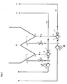
- FIG. 1 shows a first embodiment of a conveyor device according to the invention, with the granular material from a source 10 to - as in FIG. 1 exemplified-two different receiver sites 11 b2w. 12 can be promoted.
- the source 10 in this case has two outlets A1 and A2, the source 10 converging in a vertical direction from top to bottom conically to the respective outlets A1 and A2. Through the outlet ports A1 and A2, the granular material stored in the source 10 can be led out of the source 10. This results in two partial flows G1 and G2 of the granular material, which are supplied to two injectors I1 and I2 via the respective granule inlet Ib.
- the number of injectors I thus corresponds to the number of recipient sites.
- Each of the injectors I also has a propellant feed la, via which a corresponding blowing agent, for example water, can be fed into the injector I.
- a mixing of the propellant fed via the propellant feed to the feed supplied via the inlet 1b takes place Granules, wherein the granules entrained by the propellant stream and discharged via the respective outlet Ic from the respective injector I in the form of a granule-propellant mixture M1 or M2.
- Each injector 11 or 12 is preceded by a propellant pump P1 and P2, which can be driven for example via a motor M.
- a respective propellant flow T1 or T2 is generated via the pumps P1 and P2 and fed to the respective injector.
- a branch W is provided in each propellant stream T1 or T2, via which a purge stream S1 or S2 can be branched off from the propellant stream produced by the pumps P1 and P2.
- valves V may be present to regulate the purge flow.
- the purge stream is fed into the source 10 and may be directed, for example, in the outlet flow direction of the granules, so that an active discharge of the granules from the source 10 can be achieved by this purge stream.
- a separation of the granules from the propellant can take place, which thus freed of granules propellant can be supplied to the pumps P1 and P2 again.
- FIG. 2 shows an alternative embodiment of a conveying device according to the invention.
- the same reference numerals designate the same device components as in FIG FIG. 1 shown.
- the granulate source 10 has only a single outlet A, which is subsequently divided into three partial granule streams G1, G2 and G3.
- the individual granule flows G1, G2 and G3 are in each case supplied to individual injectors I1, I2 and I3, which in each case have a propellant feed Yes, a granulate feed Jb and an outlet Jc.
- the delivery device according to FIG. 2 also has three separate injectors I1, I2, I3.
- the respective injectors are preceded by propellant pumps P1, P2 and P3, wherein a separate purge stream S1, S2, S3 can also be branched off via the branches W1 to W3 and supplied to the source 10 here.
- the production plant for PA6 granules is operated in the following way:
- extraction column (10) has two outlet ports (A1, A2), 2 injectors (I1, 12) and 2 propellant pumps (P1, P2).
- the flow rate per injector is 1600 to 3400 kg PA6 granules / h.
- the granules produced have a diameter of 2.5 x 2.5 mm.
- the propellant flow is 25 to 35 m 3 of water / h at a propellant temperature of 95 to 99 ° C.
- the pressure in front of the injector is 6.5 to 9.5 bar.
- the delivery height of the granules is 36 m.
- the propellant pumps are operated with frequency converter.
Landscapes
- Engineering & Computer Science (AREA)
- Mechanical Engineering (AREA)
- Processing And Handling Of Plastics And Other Materials For Molding In General (AREA)
- Air Transport Of Granular Materials (AREA)
- Feeding, Discharge, Calcimining, Fusing, And Gas-Generation Devices (AREA)
- Structures Of Non-Positive Displacement Pumps (AREA)
Description
- Die vorliegende Erfindung betrifft eine Förderungsvorrichtung zur Förderung von in einer Quelle bevorratetem granulären Material gemäß dem Oberbegriff des Anspruchs 1, beispielsweise Polyamid 6 (PA6)-Granulat, zu mehreren Empfängerstellen, wobei die Förderungsvorrichtung eine der Anzahl an Empfängerstellen entsprechenden Anzahl von Injektoren aufweist. Zudem gibt die vorliegende Erfindung ein Verfahren zur Förderung von granulärem Material, beispielsweise PA6-Granulat von einer Quelle zu mehreren Empfängerstellen an.
- Bei der Extraktion von Polyamid-Granulaten (und Granulaten der Co-Polymere von Polyamid) besteht die Notwendigkeit, ein Granulat-Wasser-Gemisch über größere Entfernungen (> 20 m) und Höhen (> 10 m) zu transportieren. Dies geschieht zwischen einzelnen Extraktionsreaktoren bei mehrstufiger Extraktion sowie zwischen letztem Extraktionsreaktor und nachgeschalteter Trockenstufe. Hierzu hat sich neben der Förderung des Granulat-Wasser-Gemisches mittels dafür geeigneten Pumpen (Freistrompumpe mit offenem Laufrad) auch die Förderung mittels Injektoren (statische Treibstrompumpe) bewährt. Mittels eines Treibstromes wird das Granulat durch den Injektor gefördert und zusammen mit dem Treibstrom zur Empfängerstelle geleitet. Dort wird der Treibmittelstrom abgetrennt und wieder zurück zur Treibmittelpumpe geführt. Aus Kostengründen wird der Einsatz von Injektoren bei einer Förderung von einer Sendestelle zu jeweils einer Empfängerstelle bevorzugt. Die Treibstrompumpe beim Einsatz von Injektoren, die in der Regel als mehrstufige Kreiselpumpe ausgeführt ist, ist in der Regel günstiger als die Spezialpumpe, die für die Förderung eines Granulat-Wasser-Gemisches ohne Schädigung des Granulates notwendig ist. Der Wirkungsgrad einer derartigen Pumpe ist in der Regel deutlich schlechter als der Wirkungsgrad einer mehrstufigen Pumpe mit geschlossenem Laufrad.
- Die Regelung der Granulat-Fördermenge erfolgt in der Regel mittels Zellrad-schleuse, die im Zustrom der Förderpumpe oder des injektors installiert ist. Der Einsatz von Zellradschleusen ist besonders aufgrund der korrosiven Wirkung des Polyamid-Monomers Caprolactam sehr aufwendig und kostspielig Es müssen sehr leistungsfähige und korrosionsbeständige Dichtungsmaterialien verwendet werden.
- Eine Förderungsvorrichtung für Granulat sowie ein Verfahren zur Förderung von Granulat ist bereits aus der
WO 2009/157857 A1 bekannt. In dieser Erfindung wird mit Hilfe von komprimierter Luft und Wasser eine Mischung aus Granulat und Flüssigkeit durch ein Rohrsystem transportiert. Das Rohrsystem ist dabei nur an einer Stelle mit dem Behälter verbunden. - Kern und Aufgabe dieser Erfindung ist die Entwicklung eines Fördersystems für ein Granulat-Wasser-Gemisch von einer Sendestelle bzw. Quelle zu mehreren Empfängerstellen, z.B. Granulat-Wasser-Transport von dem letzten Extraktionsreaktor zu mehreren parallel nachgeschalteten Trocknungsreaktoren. Hierbei soll aus Kostengründen auf den Einsatz von Zellradschleusen und dem Einsatz von Spezialpumpen (offenes Laufrad oder Freistrompumpe) verzichtet werden, trotzdem jedoch eine genaue Dosierbarkeit der Förderströme gewährleistet werden.
- Es ist daher Aufgabe der vorliegenden Erfindung, eine Förderungsvorrichtung anzugeben, die auf zuverlässige Art und Weise die Förderung von granulärem Material von einer Quelle zu mehreren Empfängerstellen ermöglicht. Ebenso ist es Aufgabe der vorliegenden Erfindung, ein entsprechendes Förderungsverfahren für granuläres Material anzugeben.
- Diese Aufgabe wird bezüglich der Förderungsvorrichtung mit den Merkmalen des Anspruchs 1, bezüglich eines Verfahrens zur Förderung von Granulatmaterial mit den Merkmalen des Anspruchs 13 gelöst. Die jeweiligen abhängigen Ansprüche stellen dabei vorteilhafte Weiterbildungen dar.
- Erfindungsgemäß wird somit eine Förderungsvorrichtung mit den Merkmalen des Anspruchs 1 zur Förderung von in einer Quelle bevorratetem granulären Material von der Quelle zu mehreren Empfängerstellen angegeben, die eine Anzahl der Empfängerstellen entsprechende Anzahl von Injektoren aufweist, wobei jeder Injektor einen Treibmittelzulauf, einen mit einem Auslass der Quelle verbundenen Granulateinlass sowie einen Auslass für ein Gemisch aus Treibmittel und Granulat aufweist, und jedem Injektor über den jeweiligen Treibmittelzulauf mindestens eine Treibmittelpumpe vorgeschaltet und zwischen jedem Injektor und der mindestens einen vorgeschalteten Treibmittelpumpe mindestens eine Abzweigung zur Abtrennung eines Spülstroms des Treibmittels in die Quelle vorhanden ist.
- Gemäß der vorliegenden Erfindung ist somit vorgesehen, dass zur Förderung von granulärem Material zu mehreren Empfängerstationen, insbesondere in Form von Granulat-Wasser-Gemischen, parallel installierte Injektoren verwendet werden.
- Eine derartige Förderungsvorrichtung bietet die nachfolgenden Vorteile:
- Die Investitionskosten für die beschriebene Vorrichtung sind deutlich niedriger als die Investitionskosten die bei der Kombination aus Zellradschleuse mit Spezialpumpe oder Zellradschleuse mit Injektor entstehen würden.
- Die Genauigkeit der Regelung der Granulat-Fördermenge ist gleichwertig mit der Genauigkeit die mittels Zellradschleuse erreicht werden kann.
- Über die Rückführung von Extraktionsflüssigkeit, das mit dem Granulat aus dem Extraktionsreaktor heraus gefördert wurde, wird im Auslass des Extraktionsreaktors eine Flüssigkeitsströmung in Richtung des Injektors erzeugt. Hierdurch wird die Strömungsgeschwindigkeit des Granulates erhöht und die Dimension der Auslassstutzen kann reduziert werden. Dies ist bei dem Einsatz von Zellradschleusen nicht möglich.
- Die Betriebskosten bei der Verwendung von Injektoren sind geringfügig niedriger als bei Verwendung einer Spezialpumpe mit niedrigem Wirkungsgrad.
- Erfindungsgemäß ist vorgesehen, dass die Förderungsvorrichtung zwischen jedem Injektor und der jeweils mindestens einen vorgeschalteten Treibmittelpumpe mindestens eine Abzweigung zur Abtrennung eines Spülstroms des Treibmittels in die Quelle vorhanden ist.
- Durch diesen Spülstrom kann ein verbesserter Austrag von granulärem Material aus der Quelle gewährleistet werden.
- Insbesondere wird dabei der Spülstrom derart in die Quelle eingespeist, dass in der Quelle bevorratetes Granulat in Richtung des Auslasses gefördert wird.
- Vorzugsweise ist der Spülstrom regulierbar, insbesondere verfügt der Spülstrom über ein Regelventil.
- Eine weitere bevorzugte Ausführungsform sieht vor, dass die mindestens eine Treibmittelpumpe eine mehrstufige Kreiselpumpe mit geschlossenem oder offenem Laufrad ist.
- Vorteilhaft für die Ausführung ist die Verwendung eines Frequenzumformers für den Motor der Treibmittelpumpe. Durch die Modifikation der Pumpendrehzahl können Druck und Fördermenge des Treibmittels und damit auch die Menge des geförderten Granulates zur entsprechenden Empfangsstelle eingeregelt werden. Alternativ können
- Die Empfängerstellen verfügen vorteilhafterweise über eine Abtrennvorrichtung zur Abtrennung von Granulat vom Treibmittel.
- Insbesondere kann das Treibmittel der Förderungsvorrichtung im Kreislauf geführt werden, d.h. nach Abtrennen des Granulats vom Treibmittel an den Empfängerstellen wird das Treibmittel erneut zur Förderung von granulärem Material aus der Quelle zu den Empfängerstellen eingesetzt.
- Besonders vorteilhaft ist die Förderungsvorrichtung frei von Regeleinrichtungen, insbesondere Zellradschleusen und/oder Armaturen.
- Die Quelle kann insbesondere in zwei bevorzugten Ausgestaltungen ausgeführt sein, wobei die Quelle
- a) einerseits über einen Auslass für das Granulat verfügt, wobei der Granulatstrom nach Austritt aus der Quelle über eine Abzweigung in eine der Anzahl der Impfängerstellen entsprechende Anzahl von Teilströmen aufgeteilt und einem entsprechenden Granulateinlass eines Injektors zugeführt wird, oder
- b) mindestens zwei Auslässe aufweist, über die der Quelle jeweils ein Granulatstrom entnommen und einem entsprechenden Granulateinlass eines Injektors zugeführt wird.
- Insbesondere ist die Quelle ein Extraktionsreaktor zur Extraktion von Granulat.
- Das granuläre Material ist dabei insbesondere ein Granulat eines thermoplastischen Polymers, bevorzugt Polyamid-Granulat, insbesondere PA6 Granulat.
- Die Treibmittel können flüssig oder gasförmig sein und sind insbesondere ausgewählt aus der Gruppe bestehend aus Wasser oder Gemischen aus Wasser und ε-Caprolactam.
- Die vorliegende Erfindung betrifft ebenso ein Verfahren mit den Merkmalen des Anspruchs 13 zur Förderung von in einer Quelle bevorratetem granulären Material von der Quelle zu mehreren Empfängerstellen mit einer zuvor beschriebenen Förderungsvorrichtung, bei dem mittels der Treibmittelpumpe ein Treibmittelstrom erzeugt wird, derin einen Spülstrom und einen über den Treibmittelzulauf in den jeweiligen Injektor eingespeisten Treibmittelstrom geteilt wird, das granuläre Material aus dem mindestens einen Auslass der Quelle ausgetragen und über den Granulateinlass einem Injektor zugeführt und im Injektor mit dem Treibmittelstrom vermischt und als Granulat-/Treibmittelstrom über den Auslass aus dem jeweiligen Injektor ausgetragen, und dem jeweiligen Empfänger zugeführt wird.
- Das erfindungsgemäße Verfahren sieht vor, dass der Spülstrom das granuläre Material aus dem mindestens einen Auslass der Quelle austrägt und über den Granulateinlass einem Injektor zuführt.
- Vorzugsweise wird der Druck an der Abzweigung größer eingestellt als der Ausgangsdruck am Auslass der Quelle.
- Die vorliegende Erfindung wird anhand der nachfolgenden Figuren un des Beispiels näher erläutert, ohne die Erfindung jedoch auf die dargestellten speziellen Parameter zu beschränken.
-
-
Figur 1 eine erste Ausführungsform einer erfindungsgemäßen Fördervorrichtung, und -
Figur 2 eine zweite Ausführungsform einer erfindungsgemäßen Förderungsvorrichtung. -
Figur 1 zeigt eine erste Ausführungsform einer erfindungsgemäßen Förderungsvorrichtung, mit der granuläres Material von einer Quelle 10 zu - wie inFigur 1 beispielhaft dargestellt-zwei verschiedenen Empfängerstellen 11 b2w. 12 gefördert werden kann. Die Quelle 10 verfügt dabei über zwei Auslässe A1 und A2, wobei die Quelle 10 in vertikaler Richtung von oben nach unten konisch zu den jeweiligen Auslässen A1 und A2 zusammen läuft. Durch die Auslassstellen A1 und A2 kann das granuläre Material, das in der Quelle 10 bevorratet ist, aus der Quelle 10 herausgeführt werden. Dabei entstehen zwei Teilströme G1 und G2 des granulären Materials, die zwei Injektoren I1 bzw, I2 über den jeweiligen Granulateinlass Ib zugeführt werden. Die Anzahl der Injektoren I entspricht somit der Anzahl der Empfängerstellen. Jeder der Injektoren I verfügt ferner über einen Treibmittelzulauf la, über den ein entsprechendes Treibmittel, beispielsweise Wasser, in den Injektor I eingespeist werden kann. Im Injektor erfolgt eine Vermischung des über den Treibmittelzulaufs Ja zugeführten Treibmittels mit dem über den Zulauf Ib zugeführten Granulat, wobei das Granulat durch den Treibmittelstrom mitgerissen und über den jeweiligen Auslass Ic aus dem jeweiligen Injektor I in Form eines Granulat-Treibmittel-gemischs M1 bzw. M2 ausgetragen wird. Jedem Injektor 11 bzw. 12 ist eine Treibmittelpumpe P1 bzw. P2 vorgeschaltet, die beispielsweise über einen Motor M angetrieben werden kann. Über die Pumpen P1 bzw. P2 wird ein jeweiliger Treibmittelstrom T1 bzw. T2 erzeugt und dem jeweiligen Injektor zugeführt. Gemäß der speziellen Ausgestaltungsform nachFigur 1 ist in jedem Treibmittelstrom T1 bzw. T2 eine Abzweigung W vorgesehen, über die aus dem durch die Pumpen P1 bzw. P2 erzeugten Treibmittelstrom ein Spülstrom S1 bzw. S2 abgezweigt werden kann. Im Spülstrom können Ventile V zur Regulierung des Spülstroms vorhanden sein. Der Spülstrom wird dabei in die Quelle 10 eingespeist und kann beispielsweise in Auslassströmungsrichtung des Granulates gerichtet sein, sodass durch diesen Spülstrom ein aktiver Austrag des Granulats aus der Quelle 10 erreicht werden kann. An den Empfängerstellen 11 und 12 kann eine Abtrennung des Granulates vom Treibmittel erfolgen, das somit vom Granulat befreite Treibmittel kann erneut den Pumpen P1 bzw. P2 zugeführt werden. -
Figur 2 zeigt eine alternative Ausführungsform einer erfindungsgemäßen Förderungsvorrichtung. Gleiche Bezugszeichen bezeichnen dabei gleiche Vorrichtungsbestandteile wie inFigur 1 dargestellt. Im Unterschied zurFigur 1 weist dabei die Granulatquelle 10 nur einen einzigen Auslass A auf, der im Anschluss in drei Teilgranulatströme G1, G2 und G3 aufgeteilt wird. Die einzelnen Granulatströme G1, G2 und G3 werden dabei jeweils einzelnen Injektoren I1, I2 und I3, die jeweils über einen Treibmittelzulauf Ja, einen Granulatzulauf Jb sowie einen Auslass Jc aufweisen, zugeführt. Im Beispielsfall derFigur 2 sind drei Empfängerstellen 11, 12 und 13 vorhanden, weswegen die Förderungsvorrichtung gemäßFigur 2 auch über drei separate Injektoren I1, I2, I3 verfügt. Den jeweiligen Injektoren sind Treibmittelpumpen P1, P2 und P3 vorgeschaltet, wobei auch hier über die Abzweigungen W1 bis W3 ein separater Spülstrom S1, S2, S3 abgezweigt und der Quelle 10 zugeführt werden kann. - Die Produktionsanlage für PA6-Granulat wird in folgender Weise betrieben:
- Die in
Fig. 1 dargestellte Extraktionskolonne (10) weist zwei Auslassstutzen (A1, A2), 2 Injektoren (I1, 12) und 2 Treibmittelpumpen (P1, P2) auf. Die Fördermenge pro Injektor beträgt 1600 bis 3400 kg PA6-Granulat/h. Das erzeugte Granulat weist einen Durchmesser von 2,5 x 2,5 mm auf. Der Treibmittelstrom beträgt 25 bis 35 m3 Wasser/h bei einer Treibmitteltemperatur von 95 bis 99 °C. Der Druck vor dem Injektor liegt bei 6,5 bis 9,5 bar. Die Förderhöhe des Granulat beträgt 36 m. Die Treibmittelpumpen werden mit Frequenzumformer betrieben.
Claims (17)
- Förderungsvorrichtung zur Förderung von in einer Quelle (10) bevorratetem granulären Material von der Quelle (10) zu mehreren Empfängerstellen (11, 12, 13, ...), umfassend
eine der Anzahl der Empfängerstellen (11, 12, 13, ...) entsprechende Anzahl von Injektoren (I1, I2, I3, ...), wobei jeder Injektor (I1, I2, I3, ...) einen Treibmittelzulauf (la), einen mit einem Auslass (A) der Quelle (10) verbundenen Granulateinlass (Ib) sowie einen Auslass (Ic) für ein Gemisch aus Treibmittel und Granulat aufweist,
dadurch gekennzeichnet, dass jedem Injektor (I3, I2, I3, ...) über den jeweiligen Treibmittelzulauf (la) mindestens eine Treibmittelpumpe (P1, P2, P3, ...) vorgeschaltet ist und zwischen jedem Injektor (I1, I2, I3, ...) und der jeweils mindestens einen vorgeschalteten Treibmittelpumpe (P1, P2, P3, ...) mindestens eine Abzweigung (W) zur Abtrennung eines Spülstroms (S1, S2, S3, ...) des Treibmittels in die Quelle (10) vorhanden ist. - Förderungsvorrichtung nach einem der vorhergehenden Ansprüche, dadurch gekennzeichnet, dass der Spülstrom (S1, S2, S3, ...) derart in die Quelle (10) eingespeist wird, dass in der Quelle (10) bevorratetes Granulat in Richtung des Auslasses (A) gefördert wird.
- Förderungsvorrichtung nach einem der vorhergehenden Ansprüche, dadurch gekennzeichnet, dass der Spülstrom (S1, S2, S3, ...) regulierbar ist, insbesondere, dass der Spülstrom (S1, S2, S3, ...) über ein Regelventil (V) verfügt.
- Förderungsvorrichtung nach einem der vorhergehenden Ansprüche, dadurch gekennzeichnet, dass die mindestens eine Treibmittelpumpe (P1, P2, P3, ...) eine mehrstufige Kreiselpumpe mit geschlossenem oder offenem Laufrad ist.
- Förderungsvorrichtung nach Anspruch 5, dadurch gekennzeichnet, dass der Druck und die Fördermenge des Treibmittelstromes am Treibmittelzulauf (la) einregelbar ist, entweder über die Drehzahl der Treibmittelpumpe (P1, P2, P3, ...) oder über die Verwendung eines Regelventils zwischen Abzweigung (W1, W2, W3, ...) und dem Eingang des Injektors (I1, I2, I3, ...).
- Förderungsvorrichtung nach einem der vorhergehenden Ansprüche, dadurch gekennzeichnet, dass die Empfängerstellen (11, 12, 13, ...) über eine Abtrennvorrichtung zur Abtrennung von Granulat vom Treibmittel verfügen.
- Förderungsvorrichtung nach einem der vorhergenenden Ansprüche, dadurch gekennzeichnet, dass das Treibmittel im Kreislauf geführt wird.
- Förderungsvorrichtung nach einem der vorhergehenden Ansprüche, dadurch gekennzeichnet, dass die Förderungsvorrichtung frei ist von Regeleinrichtungen, insbesondere Zellradschleusen und/oder Armaturen.
- Förderungsvorrichtung nach einem der vorhergehenden Ansprüche, dadurch gekennzeichnet, dass die Quelle (10)a) über einen Auslass (A) für das Granulat verfügt, wobei der Granulatstrom nach Austritt aus der Quelle (10) über eine Abzweigung (W2) in eine der Anzahl der Empfängerstellen (11, 12, 13, ...) entsprechende Anzahl von Teilströmen (G1, G2, G3) aufgeteilt und einem entsprechenden Granulateinlass (Ib) eines Injektors (I1, I2, I3, ...) zugeführt wird, oderb) mindestens zwei Auslässe (A1, A2, ...) aufweist, über die der Quelle (10) jeweils ein Granulatstrom (G1, G2, ...) entnommen und einem entsprechenden Granulateinlass (Ib) eines Injektors (I1, I2, ...) zugeführt wird.
- Förderungsvorrichtung nach einem der vorhergehenden Ansprüche, dadurch gekennzeichnet, dass die Quelle (10) ein Extraktionsreaktor zur Extraktion von Granulat ist.
- Förderungsvorrichtung nach einem der vorhergehenden Ansprüche, dadurch gekennzeichnet, dass das granuläre Material ein Granulat eines thermoplastischen Polymers, bevorzugt Polyamid-Granulat, insbesondere PA 6 Granulat ist.
- Förderungsvorrichtung nach einem der vorhergehenden Ansprüche, dadurch gekennzeichnet, dass das Treibmittel flüssig oder gasförmig ist und insbesondere ausgewählt ist aus der Gruppe bestehend aus Wasser oder Gemischen aus Wasser und E-Caprofactam.
- Verfahren zur Förderung von in einer Quelle (10) bevorratetem granulären Material von der Quelle (10) zu mehreren Empfängerstellen (11, 12, 13, ...) mit einer Förderungsvorrichtung nach einem der vorhergehenden Ansprüche, bei dem
mittels der Treibmittelpumpe (P1, P2, P3, ...) ein Treibmittelstrom erzeugt wird, der in einen Spülstrom (S1, S2, S3, ...) und einen über den Treibmittelzulauf (la) in den jeweiligen Injektor (I1, I2, I3, ...) eingespeisten Treibmittelstrom (T1, T2, T3, ...) geteilt, das granuläre Material aus dem mindestens einen Auslass (A) der Quelle ausgetragen und über den Granulateinlass (Ib) einem Injektor (I1, I2, I3, ...) zugeführt und im Injektor (I1, I2, I3, ...) mit dem Treibmittelstrom (T1, T2, T3, ...) vermischt und als Granulat-/Treibmittelstrom (M1, M2, M3, ...) über den Auslass (Ic) aus dem jeweiligen Injektor (I1, I2, I3, ...) ausgetragen, und
dem jeweiligen Empfänger (11, 12, 13, ...) zugeführt wird. - Verfahren nach vorhergehendem Anspruch, dadurch gekennzeichnet, dass
das granuläre Material mittels des Spülstroms (S1, S2, S3, ...) aus dem mindestens einen Auslass (A) der Quelle ausgetragen und über den Granulateinlass (Ib) einem Injektor (I1, I2, I3, ...) zugeführt wird. - Verfahren nach einem der beiden vorhergehenden Ansprüche,
dadurch gekennzeichnet, dass der Druck an der Abzweigung (W, W2) größer eingestellt wird als der Ausgangsdruck am Auslass (A, A1, A2) der Quelle (10). - Verfahren nach einem der Ansprüche 13 bis 15, dadurch gekennzeichnet, dass an den Empfängerstellen (11, 12, 13, ...) eine Abtrennung des granulären Materials vom Treibmittel erfolgt.
- Verfahren nach einem der Ansprüche 13 bis 16, dadurch gekennzeichnet, dass das Treibmittel in einem Kreislauf geführt wird.
Priority Applications (9)
| Application Number | Priority Date | Filing Date | Title |
|---|---|---|---|
| ES13152700.4T ES2603728T3 (es) | 2013-01-25 | 2013-01-25 | Dispositivo y procedimiento para transportar granulado |
| SI201330360A SI2759499T1 (sl) | 2013-01-25 | 2013-01-25 | Naprava in postopek za transportiranje granulata |
| PL13152700T PL2759499T3 (pl) | 2013-01-25 | 2013-01-25 | Urządzenie i sposób przenoszenia granulatu |
| EP13152700.4A EP2759499B1 (de) | 2013-01-25 | 2013-01-25 | Vorrichtung und Verfahren zur Förderung von Granulat |
| CN201320124657.XU CN203638748U (zh) | 2013-01-25 | 2013-03-19 | 颗粒输送装置 |
| US14/762,105 US9643797B2 (en) | 2013-01-25 | 2014-01-20 | Conveying device for granulate and also method for conveying granulate |
| PCT/EP2014/051003 WO2014114586A1 (de) | 2013-01-25 | 2014-01-20 | Vorrichtung und verfahren zur förderung von granulat |
| TW103102199A TWI670218B (zh) | 2013-01-25 | 2014-01-22 | 用於粒料之輸送裝置以及用於輸送粒料之方法 |
| SA515360806A SA515360806B1 (ar) | 2013-01-25 | 2015-07-23 | جهاز وطريقة لنقل الحبيبات |
Applications Claiming Priority (1)
| Application Number | Priority Date | Filing Date | Title |
|---|---|---|---|
| EP13152700.4A EP2759499B1 (de) | 2013-01-25 | 2013-01-25 | Vorrichtung und Verfahren zur Förderung von Granulat |
Publications (2)
| Publication Number | Publication Date |
|---|---|
| EP2759499A1 EP2759499A1 (de) | 2014-07-30 |
| EP2759499B1 true EP2759499B1 (de) | 2016-08-24 |
Family
ID=47681699
Family Applications (1)
| Application Number | Title | Priority Date | Filing Date |
|---|---|---|---|
| EP13152700.4A Active EP2759499B1 (de) | 2013-01-25 | 2013-01-25 | Vorrichtung und Verfahren zur Förderung von Granulat |
Country Status (9)
| Country | Link |
|---|---|
| US (1) | US9643797B2 (de) |
| EP (1) | EP2759499B1 (de) |
| CN (1) | CN203638748U (de) |
| ES (1) | ES2603728T3 (de) |
| PL (1) | PL2759499T3 (de) |
| SA (1) | SA515360806B1 (de) |
| SI (1) | SI2759499T1 (de) |
| TW (1) | TWI670218B (de) |
| WO (1) | WO2014114586A1 (de) |
Families Citing this family (4)
| Publication number | Priority date | Publication date | Assignee | Title |
|---|---|---|---|---|
| ES2582302T3 (es) | 2011-07-11 | 2016-09-12 | Uhde Inventa-Fischer Gmbh | Procedimiento para la producción de una solución acuosa de sales |
| ES2671738T3 (es) | 2013-02-08 | 2018-06-08 | Uhde Inventa-Fischer Gmbh | Reactor con tubo de condensación vertical y procedimiento para la polimerización de poliamidas en un reactor de este tipo |
| US9854729B2 (en) * | 2015-10-29 | 2018-01-02 | Brooklyn Bridge To Cambodia, Inc. | Seed planter using air propulsion |
| TWI630500B (zh) * | 2017-09-08 | 2018-07-21 | 崴立飛科技有限公司 | 粒料級配系統及其方法 |
Family Cites Families (22)
| Publication number | Priority date | Publication date | Assignee | Title |
|---|---|---|---|---|
| US1908220A (en) * | 1931-12-07 | 1933-05-09 | Frank D Chapman | Hydraulic conveyer |
| US3490654A (en) * | 1968-01-22 | 1970-01-20 | Harry C Fischer | Controlled volume systems for pneumatic discharge of powdered and granular materials and the like |
| US5071289A (en) * | 1989-12-27 | 1991-12-10 | Alpheus Cleaning Technologies Corp. | Particulate delivery system |
| JP2703690B2 (ja) * | 1992-04-13 | 1998-01-26 | 三菱マテリアル株式会社 | 超微粉末の定量バッチ供給装置 |
| DE19906496A1 (de) * | 1999-02-17 | 2000-08-31 | Waeschle Gmbh | Verfahren und Vorrichtung zur hydraulischen Förderung von Schüttgut |
| DE19921162C1 (de) * | 1999-05-07 | 2000-10-12 | Waeschle Gmbh | Verfahren und Vorrichtung zur hydraulischen Förderung von Schüttgut |
| ITMI20011352A1 (it) * | 2001-06-27 | 2002-12-27 | 3V Cogeim S P A | Gruppo di scarico del prodotto essiccato particolarmente per filtri essicatori e simili |
| US7846399B2 (en) * | 2004-03-23 | 2010-12-07 | W.R. Grace & Co.-Conn. | System and process for injecting catalyst and/or additives into a fluidized catalytic cracking unit |
| DE102004018023B4 (de) * | 2004-04-14 | 2008-08-14 | Coperion Waeschle Gmbh & Co. Kg | Verfahren und Anlage zur hydraulischen Förderung von Schüttgut |
| US7270249B1 (en) * | 2005-03-03 | 2007-09-18 | Burkhead Ronnie J | Pneumatic metering apparatus for flowable solids product |
| US8844615B2 (en) * | 2006-09-15 | 2014-09-30 | Schlumberger Technology Corporation | Oilfield material delivery mechanism |
| US7311474B1 (en) * | 2007-01-04 | 2007-12-25 | Itswa Co., Ltd. | Pellet loader |
| SE532897C2 (sv) * | 2008-06-24 | 2010-05-04 | Uvaan Hagfors Teknologi Ab | Förfarande och anordning för utmatning av granulat från botten av en tank, som förutom granulat innehåller vatten |
| PL2532698T3 (pl) * | 2011-06-08 | 2016-12-30 | Sposób i urządzenie do bezpośredniej, ciągłej modyfikacji stopionych polimerów | |
| CN102827643A (zh) * | 2011-06-14 | 2012-12-19 | 通用电气公司 | 输送装置、系统及方法 |
| ES2582302T3 (es) * | 2011-07-11 | 2016-09-12 | Uhde Inventa-Fischer Gmbh | Procedimiento para la producción de una solución acuosa de sales |
| CN103998143B (zh) * | 2011-10-27 | 2016-07-13 | 格瑞克明尼苏达有限公司 | 真空系统供料辅助机构 |
| US9086164B2 (en) * | 2012-06-29 | 2015-07-21 | General Electric Company | Apparatus and method of delivering a fluid using a non-mechanical eductor pump and lock hopper |
| EP2903732B1 (de) * | 2012-10-01 | 2016-11-23 | Univation Technologies, LLC | Systeme und verfahren zur harzlagerung |
| ES2671738T3 (es) * | 2013-02-08 | 2018-06-08 | Uhde Inventa-Fischer Gmbh | Reactor con tubo de condensación vertical y procedimiento para la polimerización de poliamidas en un reactor de este tipo |
| PL2772305T3 (pl) * | 2013-02-27 | 2018-03-30 | Uhde Inventa-Fischer Gmbh | Urządzenie do polimeryzacji i sposób wytwarzania polimerów termoplastycznych |
| US8936416B2 (en) * | 2013-05-01 | 2015-01-20 | Crystal-Mark, Inc., A Swan Technologies Corporation | Fluidized particle abrasion device with precision control |
-
2013
- 2013-01-25 ES ES13152700.4T patent/ES2603728T3/es active Active
- 2013-01-25 PL PL13152700T patent/PL2759499T3/pl unknown
- 2013-01-25 SI SI201330360A patent/SI2759499T1/sl unknown
- 2013-01-25 EP EP13152700.4A patent/EP2759499B1/de active Active
- 2013-03-19 CN CN201320124657.XU patent/CN203638748U/zh not_active Expired - Lifetime
-
2014
- 2014-01-20 US US14/762,105 patent/US9643797B2/en active Active
- 2014-01-20 WO PCT/EP2014/051003 patent/WO2014114586A1/de not_active Ceased
- 2014-01-22 TW TW103102199A patent/TWI670218B/zh active
-
2015
- 2015-07-23 SA SA515360806A patent/SA515360806B1/ar unknown
Also Published As
| Publication number | Publication date |
|---|---|
| WO2014114586A1 (de) | 2014-07-31 |
| PL2759499T3 (pl) | 2017-02-28 |
| TWI670218B (zh) | 2019-09-01 |
| ES2603728T3 (es) | 2017-03-01 |
| US20150314969A1 (en) | 2015-11-05 |
| EP2759499A1 (de) | 2014-07-30 |
| SA515360806B1 (ar) | 2019-04-28 |
| CN203638748U (zh) | 2014-06-11 |
| TW201437131A (zh) | 2014-10-01 |
| SI2759499T1 (sl) | 2017-01-31 |
| US9643797B2 (en) | 2017-05-09 |
Similar Documents
| Publication | Publication Date | Title |
|---|---|---|
| EP3282823B1 (de) | Landwirtschaftliche verteilvorrichtung zum ausbringen von koernigem gut und verfahren zum umgang mit koernigem gut | |
| EP2378230A2 (de) | Vorrichtung zum Kühlen oder Heizen von Schüttgut | |
| EP3401248A1 (de) | Verfahren zur pneumatischen förderung von kunststoffgranulat | |
| WO2014114586A1 (de) | Vorrichtung und verfahren zur förderung von granulat | |
| EP3261894A1 (de) | Pneumatische fördereinrichtung und dosieranlage sowie sandungsanlage mit einer strahlpumpe für rieselfähiges gut | |
| EP2465617A1 (de) | Verfahren und Vorrichtung zur Abscheidung von feinen Partikeln aus granulatförmigen Schüttgütern in einer Rohrleitung | |
| EP3317538A1 (de) | Vorrichtung zum herstellen einer mischung aus wenigstens einem gas und wenigstens einer flüssigen kunststoffkomponente | |
| DE102013104740B4 (de) | Vorrichtung und Verfahren zum Ausscheiden von Verunreinigungen aus einem Schüttgutstrom | |
| EP3317063B1 (de) | Vorrichtung mit intermittierender bereitstellung einer mit gas vermischten flüssigen kunststoffkomponente | |
| DE102018105678A1 (de) | Anlage zur Aufbereitung von Brauchwasser, Wasserbelüftungsaggregat und Verfahren zur Brauchwasseraufbereitung | |
| EP3691951B1 (de) | Strömungseinrichtung und verfahren zum steuern und/oder einstellen eines drucks in einer pneumatischen sandfördervorrichtung für ein schienenfahrzeug und sandfördervorrichtung mit einer strömungseinrichtung | |
| AT502048B1 (de) | Verfahren und vorrichtung zum beschicken von verarbeitungsanlagen | |
| EP1715764A1 (de) | Verfahren zur diafiltration eines produktes und vorrichtung zur durchfuhrung des verfahrens | |
| EP0908215A2 (de) | Vorrichtung zur Bindung bzw. Niederschlagung von Staub | |
| DE2363505A1 (de) | Aufgabevorrichtung einer druckluftfoerderanlage fuer schuettgut | |
| DE102004005907A1 (de) | Verminderung von Biuret und freiem Ammoniak bei einem Verfahren zur Herstellung harnstoffhaltigen Düngemittelgranulats | |
| DE10349871B4 (de) | Verfahren und Einrichtung zur Versorgung von mehreren pneumatischen Förder-Anlagen mit Fördergas unter Druck | |
| DE2819726A1 (de) | Schwerkraftmischer fuer pulverfoermiges bis koerniges gut | |
| DE102017207035A1 (de) | Verfahren und Vorrichtung zur Herstellung eines Granulats | |
| DE102017122859B3 (de) | Strömungseinrichtung und Verfahren zum Steuern und/oder Einstellen eines Gegendrucks in einer pneumatischen Sandfördervorrichtung für ein Schienenfahrzeug und Sandfördervorrichtung mit einer Strömungseinrichtung | |
| DE3704637A1 (de) | Verfahren und vorrichtung zum einbringen von adsorptionsmittel in rauchgaskanaele | |
| DE19906496A1 (de) | Verfahren und Vorrichtung zur hydraulischen Förderung von Schüttgut | |
| DE3407402A1 (de) | Pneumatisches foerderverfahren fuer fliessfaehige schuettgueter | |
| DE102023200069A1 (de) | Modulares Partikelaustragungssystem | |
| DE19912298B4 (de) | Verfahren und Vorrichtung zur Aufbereitung eines körnigen Füllstoffes |
Legal Events
| Date | Code | Title | Description |
|---|---|---|---|
| PUAI | Public reference made under article 153(3) epc to a published international application that has entered the european phase |
Free format text: ORIGINAL CODE: 0009012 |
|
| 17P | Request for examination filed |
Effective date: 20130125 |
|
| AK | Designated contracting states |
Kind code of ref document: A1 Designated state(s): AL AT BE BG CH CY CZ DE DK EE ES FI FR GB GR HR HU IE IS IT LI LT LU LV MC MK MT NL NO PL PT RO RS SE SI SK SM TR |
|
| AX | Request for extension of the european patent |
Extension state: BA ME |
|
| R17P | Request for examination filed (corrected) |
Effective date: 20150119 |
|
| RBV | Designated contracting states (corrected) |
Designated state(s): AL AT BE BG CH CY CZ DE DK EE ES FI FR GB GR HR HU IE IS IT LI LT LU LV MC MK MT NL NO PL PT RO RS SE SI SK SM TR |
|
| 17Q | First examination report despatched |
Effective date: 20150828 |
|
| GRAP | Despatch of communication of intention to grant a patent |
Free format text: ORIGINAL CODE: EPIDOSNIGR1 |
|
| INTG | Intention to grant announced |
Effective date: 20160317 |
|
| GRAS | Grant fee paid |
Free format text: ORIGINAL CODE: EPIDOSNIGR3 |
|
| GRAA | (expected) grant |
Free format text: ORIGINAL CODE: 0009210 |
|
| AK | Designated contracting states |
Kind code of ref document: B1 Designated state(s): AL AT BE BG CH CY CZ DE DK EE ES FI FR GB GR HR HU IE IS IT LI LT LU LV MC MK MT NL NO PL PT RO RS SE SI SK SM TR |
|
| REG | Reference to a national code |
Ref country code: GB Ref legal event code: FG4D Free format text: NOT ENGLISH |
|
| REG | Reference to a national code |
Ref country code: CH Ref legal event code: EP |
|
| REG | Reference to a national code |
Ref country code: AT Ref legal event code: REF Ref document number: 822861 Country of ref document: AT Kind code of ref document: T Effective date: 20160915 |
|
| REG | Reference to a national code |
Ref country code: IE Ref legal event code: FG4D Free format text: LANGUAGE OF EP DOCUMENT: GERMAN |
|
| REG | Reference to a national code |
Ref country code: DE Ref legal event code: R096 Ref document number: 502013004113 Country of ref document: DE |
|
| REG | Reference to a national code |
Ref country code: CH Ref legal event code: NV Representative=s name: FIAMMENGHI-FIAMMENGHI, CH |
|
| REG | Reference to a national code |
Ref country code: NL Ref legal event code: FP |
|
| REG | Reference to a national code |
Ref country code: LT Ref legal event code: MG4D |
|
| PG25 | Lapsed in a contracting state [announced via postgrant information from national office to epo] |
Ref country code: RS Free format text: LAPSE BECAUSE OF FAILURE TO SUBMIT A TRANSLATION OF THE DESCRIPTION OR TO PAY THE FEE WITHIN THE PRESCRIBED TIME-LIMIT Effective date: 20160824 Ref country code: LT Free format text: LAPSE BECAUSE OF FAILURE TO SUBMIT A TRANSLATION OF THE DESCRIPTION OR TO PAY THE FEE WITHIN THE PRESCRIBED TIME-LIMIT Effective date: 20160824 Ref country code: NO Free format text: LAPSE BECAUSE OF FAILURE TO SUBMIT A TRANSLATION OF THE DESCRIPTION OR TO PAY THE FEE WITHIN THE PRESCRIBED TIME-LIMIT Effective date: 20161124 Ref country code: FI Free format text: LAPSE BECAUSE OF FAILURE TO SUBMIT A TRANSLATION OF THE DESCRIPTION OR TO PAY THE FEE WITHIN THE PRESCRIBED TIME-LIMIT Effective date: 20160824 Ref country code: HR Free format text: LAPSE BECAUSE OF FAILURE TO SUBMIT A TRANSLATION OF THE DESCRIPTION OR TO PAY THE FEE WITHIN THE PRESCRIBED TIME-LIMIT Effective date: 20160824 |
|
| PG25 | Lapsed in a contracting state [announced via postgrant information from national office to epo] |
Ref country code: PT Free format text: LAPSE BECAUSE OF FAILURE TO SUBMIT A TRANSLATION OF THE DESCRIPTION OR TO PAY THE FEE WITHIN THE PRESCRIBED TIME-LIMIT Effective date: 20161226 Ref country code: SE Free format text: LAPSE BECAUSE OF FAILURE TO SUBMIT A TRANSLATION OF THE DESCRIPTION OR TO PAY THE FEE WITHIN THE PRESCRIBED TIME-LIMIT Effective date: 20160824 Ref country code: GR Free format text: LAPSE BECAUSE OF FAILURE TO SUBMIT A TRANSLATION OF THE DESCRIPTION OR TO PAY THE FEE WITHIN THE PRESCRIBED TIME-LIMIT Effective date: 20161125 Ref country code: LV Free format text: LAPSE BECAUSE OF FAILURE TO SUBMIT A TRANSLATION OF THE DESCRIPTION OR TO PAY THE FEE WITHIN THE PRESCRIBED TIME-LIMIT Effective date: 20160824 |
|
| REG | Reference to a national code |
Ref country code: ES Ref legal event code: FG2A Ref document number: 2603728 Country of ref document: ES Kind code of ref document: T3 Effective date: 20170301 |
|
| PG25 | Lapsed in a contracting state [announced via postgrant information from national office to epo] |
Ref country code: EE Free format text: LAPSE BECAUSE OF FAILURE TO SUBMIT A TRANSLATION OF THE DESCRIPTION OR TO PAY THE FEE WITHIN THE PRESCRIBED TIME-LIMIT Effective date: 20160824 Ref country code: RO Free format text: LAPSE BECAUSE OF FAILURE TO SUBMIT A TRANSLATION OF THE DESCRIPTION OR TO PAY THE FEE WITHIN THE PRESCRIBED TIME-LIMIT Effective date: 20160824 |
|
| REG | Reference to a national code |
Ref country code: DE Ref legal event code: R097 Ref document number: 502013004113 Country of ref document: DE |
|
| PG25 | Lapsed in a contracting state [announced via postgrant information from national office to epo] |
Ref country code: BG Free format text: LAPSE BECAUSE OF FAILURE TO SUBMIT A TRANSLATION OF THE DESCRIPTION OR TO PAY THE FEE WITHIN THE PRESCRIBED TIME-LIMIT Effective date: 20161124 Ref country code: SK Free format text: LAPSE BECAUSE OF FAILURE TO SUBMIT A TRANSLATION OF THE DESCRIPTION OR TO PAY THE FEE WITHIN THE PRESCRIBED TIME-LIMIT Effective date: 20160824 Ref country code: BE Free format text: LAPSE BECAUSE OF NON-PAYMENT OF DUE FEES Effective date: 20170131 Ref country code: SM Free format text: LAPSE BECAUSE OF FAILURE TO SUBMIT A TRANSLATION OF THE DESCRIPTION OR TO PAY THE FEE WITHIN THE PRESCRIBED TIME-LIMIT Effective date: 20160824 Ref country code: CZ Free format text: LAPSE BECAUSE OF FAILURE TO SUBMIT A TRANSLATION OF THE DESCRIPTION OR TO PAY THE FEE WITHIN THE PRESCRIBED TIME-LIMIT Effective date: 20160824 Ref country code: DK Free format text: LAPSE BECAUSE OF FAILURE TO SUBMIT A TRANSLATION OF THE DESCRIPTION OR TO PAY THE FEE WITHIN THE PRESCRIBED TIME-LIMIT Effective date: 20160824 |
|
| PLBE | No opposition filed within time limit |
Free format text: ORIGINAL CODE: 0009261 |
|
| STAA | Information on the status of an ep patent application or granted ep patent |
Free format text: STATUS: NO OPPOSITION FILED WITHIN TIME LIMIT |
|
| 26N | No opposition filed |
Effective date: 20170526 |
|
| GBPC | Gb: european patent ceased through non-payment of renewal fee |
Effective date: 20170125 |
|
| PG25 | Lapsed in a contracting state [announced via postgrant information from national office to epo] |
Ref country code: MC Free format text: LAPSE BECAUSE OF FAILURE TO SUBMIT A TRANSLATION OF THE DESCRIPTION OR TO PAY THE FEE WITHIN THE PRESCRIBED TIME-LIMIT Effective date: 20160824 |
|
| REG | Reference to a national code |
Ref country code: FR Ref legal event code: ST Effective date: 20170929 |
|
| PG25 | Lapsed in a contracting state [announced via postgrant information from national office to epo] |
Ref country code: FR Free format text: LAPSE BECAUSE OF NON-PAYMENT OF DUE FEES Effective date: 20170131 |
|
| REG | Reference to a national code |
Ref country code: IE Ref legal event code: MM4A |
|
| PG25 | Lapsed in a contracting state [announced via postgrant information from national office to epo] |
Ref country code: LU Free format text: LAPSE BECAUSE OF NON-PAYMENT OF DUE FEES Effective date: 20170125 Ref country code: GB Free format text: LAPSE BECAUSE OF NON-PAYMENT OF DUE FEES Effective date: 20170125 |
|
| REG | Reference to a national code |
Ref country code: BE Ref legal event code: MM Effective date: 20170131 |
|
| PG25 | Lapsed in a contracting state [announced via postgrant information from national office to epo] |
Ref country code: IE Free format text: LAPSE BECAUSE OF NON-PAYMENT OF DUE FEES Effective date: 20170125 |
|
| PG25 | Lapsed in a contracting state [announced via postgrant information from national office to epo] |
Ref country code: MT Free format text: LAPSE BECAUSE OF FAILURE TO SUBMIT A TRANSLATION OF THE DESCRIPTION OR TO PAY THE FEE WITHIN THE PRESCRIBED TIME-LIMIT Effective date: 20160824 |
|
| PG25 | Lapsed in a contracting state [announced via postgrant information from national office to epo] |
Ref country code: AL Free format text: LAPSE BECAUSE OF FAILURE TO SUBMIT A TRANSLATION OF THE DESCRIPTION OR TO PAY THE FEE WITHIN THE PRESCRIBED TIME-LIMIT Effective date: 20160824 |
|
| REG | Reference to a national code |
Ref country code: AT Ref legal event code: MM01 Ref document number: 822861 Country of ref document: AT Kind code of ref document: T Effective date: 20180125 |
|
| PG25 | Lapsed in a contracting state [announced via postgrant information from national office to epo] |
Ref country code: AT Free format text: LAPSE BECAUSE OF NON-PAYMENT OF DUE FEES Effective date: 20180125 |
|
| PG25 | Lapsed in a contracting state [announced via postgrant information from national office to epo] |
Ref country code: HU Free format text: LAPSE BECAUSE OF FAILURE TO SUBMIT A TRANSLATION OF THE DESCRIPTION OR TO PAY THE FEE WITHIN THE PRESCRIBED TIME-LIMIT; INVALID AB INITIO Effective date: 20130125 |
|
| PG25 | Lapsed in a contracting state [announced via postgrant information from national office to epo] |
Ref country code: CY Free format text: LAPSE BECAUSE OF NON-PAYMENT OF DUE FEES Effective date: 20160824 |
|
| PG25 | Lapsed in a contracting state [announced via postgrant information from national office to epo] |
Ref country code: MK Free format text: LAPSE BECAUSE OF FAILURE TO SUBMIT A TRANSLATION OF THE DESCRIPTION OR TO PAY THE FEE WITHIN THE PRESCRIBED TIME-LIMIT Effective date: 20160824 |
|
| PG25 | Lapsed in a contracting state [announced via postgrant information from national office to epo] |
Ref country code: TR Free format text: LAPSE BECAUSE OF FAILURE TO SUBMIT A TRANSLATION OF THE DESCRIPTION OR TO PAY THE FEE WITHIN THE PRESCRIBED TIME-LIMIT Effective date: 20160824 |
|
| PG25 | Lapsed in a contracting state [announced via postgrant information from national office to epo] |
Ref country code: IS Free format text: LAPSE BECAUSE OF FAILURE TO SUBMIT A TRANSLATION OF THE DESCRIPTION OR TO PAY THE FEE WITHIN THE PRESCRIBED TIME-LIMIT Effective date: 20161224 |
|
| PGFP | Annual fee paid to national office [announced via postgrant information from national office to epo] |
Ref country code: ES Payment date: 20250226 Year of fee payment: 13 |
|
| PGFP | Annual fee paid to national office [announced via postgrant information from national office to epo] |
Ref country code: SI Payment date: 20250116 Year of fee payment: 13 |
|
| PGFP | Annual fee paid to national office [announced via postgrant information from national office to epo] |
Ref country code: IT Payment date: 20250129 Year of fee payment: 13 |
|
| REG | Reference to a national code |
Ref country code: CH Ref legal event code: U11 Free format text: ST27 STATUS EVENT CODE: U-0-0-U10-U11 (AS PROVIDED BY THE NATIONAL OFFICE) Effective date: 20260201 |
|
| PGFP | Annual fee paid to national office [announced via postgrant information from national office to epo] |
Ref country code: NL Payment date: 20260121 Year of fee payment: 14 |
|
| PGFP | Annual fee paid to national office [announced via postgrant information from national office to epo] |
Ref country code: DE Payment date: 20260121 Year of fee payment: 14 |
|
| PGFP | Annual fee paid to national office [announced via postgrant information from national office to epo] |
Ref country code: CH Payment date: 20260201 Year of fee payment: 14 |
|
| PGFP | Annual fee paid to national office [announced via postgrant information from national office to epo] |
Ref country code: PL Payment date: 20260119 Year of fee payment: 14 |