EP2756992A1 - Kraftfahrzeugsicherheitsanordnung und Verfahren - Google Patents
Kraftfahrzeugsicherheitsanordnung und Verfahren Download PDFInfo
- Publication number
- EP2756992A1 EP2756992A1 EP13151989.4A EP13151989A EP2756992A1 EP 2756992 A1 EP2756992 A1 EP 2756992A1 EP 13151989 A EP13151989 A EP 13151989A EP 2756992 A1 EP2756992 A1 EP 2756992A1
- Authority
- EP
- European Patent Office
- Prior art keywords
- vehicle
- safety belt
- control unit
- sensor
- collision
- Prior art date
- Legal status (The legal status is an assumption and is not a legal conclusion. Google has not performed a legal analysis and makes no representation as to the accuracy of the status listed.)
- Ceased
Links
Images

Classifications
-
- B—PERFORMING OPERATIONS; TRANSPORTING
- B60—VEHICLES IN GENERAL
- B60R—VEHICLES, VEHICLE FITTINGS, OR VEHICLE PARTS, NOT OTHERWISE PROVIDED FOR
- B60R22/00—Safety belts or body harnesses in vehicles
- B60R22/48—Control systems, alarms, or interlock systems, for the correct application of the belt or harness
-
- B—PERFORMING OPERATIONS; TRANSPORTING
- B60—VEHICLES IN GENERAL
- B60R—VEHICLES, VEHICLE FITTINGS, OR VEHICLE PARTS, NOT OTHERWISE PROVIDED FOR
- B60R21/00—Arrangements or fittings on vehicles for protecting or preventing injuries to occupants or pedestrians in case of accidents or other traffic risks
- B60R21/01—Electrical circuits for triggering passive safety arrangements, e.g. airbags, safety belt tighteners, in case of vehicle accidents or impending vehicle accidents
- B60R21/013—Electrical circuits for triggering passive safety arrangements, e.g. airbags, safety belt tighteners, in case of vehicle accidents or impending vehicle accidents including means for detecting collisions, impending collisions or roll-over
- B60R21/0134—Electrical circuits for triggering passive safety arrangements, e.g. airbags, safety belt tighteners, in case of vehicle accidents or impending vehicle accidents including means for detecting collisions, impending collisions or roll-over responsive to imminent contact with an obstacle, e.g. using radar systems
Definitions
- Embodiments herein relate to a motor vehicle safety arrangement for positioning an occupant properly relative to a back rest of a vehicle seat and restraining the occupant thus positioned on the vehicle seat in preparation of the vehicle potentially being subject to a rear-end collision.
- Still further embodiments herein relate to a motor vehicle comprising a motor vehicle safety arrangement for positioning an occupant properly relative to a back rest of a vehicle seat and restraining the occupant thus positioned on the vehicle seat in preparation of the vehicle potentially being subject to a rear-end collision.
- Collision warning systems provide a vehicle operator knowledge and awareness of objects or vehicles within a close proximity, so as to prevent colliding with those objects.
- Current collision warning systems usually rely on a sensor located on the vehicle which, upon sensing an object generates an object detection signal, which is communicated to the operator of that vehicle as a warning of a potential collision.
- Rear-end collisions may cause so called whiplash injuries to occupants of the vehicle being rear-ended.
- systems for preventing or mitigating whiplash related injuries during rear-end collisions usually rely on electric reversible seat-belt retractors or tensioners.
- WO2008002756 relates to a control system for warning a following vehicle of a potential collision with a leading vehicle.
- the leading vehicle is equipped with a rear collision warning system that can determine the range and range rate of the following vehicle using radar sensors or ultrasonic sensors.
- the control system employs an algorithm that detects the following vehicle and determines whether the potential exists for a collision with the leading vehicle.
- the algorithm compares a desired distance between the leading vehicle and the following vehicle based on the speed of the leading vehicle, and determines whether the difference between the desired distance and the actual distance is greater than a predetermined threshold. If the difference is greater than the threshold, the algorithm may provide one or more operations, such as flashing hazard lights to warn the following vehicle, or taking other courses of action in the event of an imminent collision, such as pre-tensioning seat belts.
- US6758495 relates to a method and system for restraining an occupant on a vehicle seat, the occupant being pulled into the vehicle seat is provided with a force by a belt tensioner when a critical driving state is detected and then held in a pulled-back position on the vehicle seat with a holding force.
- a forward-looking detection system for a dangerous driving state is provided, in which, when a dangerous driving state is detected, a belt tensioner is subjected to a force and the occupant is thereby pulled into the vehicle seat, and in which the occupant is held in a pulled-back position on the vehicle seat.
- a trigger criterion for belt tensioners can thus be derived by determining critical driving situations and/or with the aid of the forward-looking sensor system.
- the critical vehicle state is detected by monitoring the steering angle, distance from an object, relative velocity, vehicle deceleration, yaw angle, yaw rate, yawing acceleration, vehicle's own speed, steering angle, sharp changes in direction, jump in the road/tire friction coefficient, lateral acceleration, wheel speed and/or angle of inclination or any combination of these parameters.
- a time of collision is determined from this, i.e.
- Embodiments herein aim to provide an improved motor vehicle safety arrangement for positioning an occupant properly relative to a back rest of a vehicle seat and restraining the occupant thus positioned on the vehicle seat in preparation of the vehicle potentially being subject to a rear-end collision, the vehicle having a safety belt associated with the vehicle seat and an electric reversible safety belt retractor associated with the safety belt.
- a motor vehicle safety arrangement which comprises: a rearward-looking detection system for detecting and classifying the collision risk for an approaching object; at least one sensor for monitoring one or more vehicle parameters ; a control unit arranged to determine a driving state as critical or non-critical from the monitored vehicle parameters; and; where the control unit further is operable to control the electric reversible safety belt retractor to apply a predetermined pullback force on the safety belt to pull an occupant into the vehicle seat in response to the collision risk for an approaching object being classified as high within a predetermined time of an indicated critical driving state.
- a motor vehicle safety arrangement as above, performing belt retraction in response to the collision risk for an approaching object being classified as high within a predetermined time of an indicated critical driving state provides for taking into account driver behavior, such that the number of non-threatening instances being classified as instances where a collision is imminent can be reduced.
- At least one sensor is arranged to monitor at least one of the following vehicle parameters: vehicle velocity, steering wheel angle, vehicle yaw rate, yawing acceleration, lateral acceleration, angle of inclination and wheel speeds.
- control unit is arranged to determine critical driving from the monitored vehicle parameters when one or more of the vehicle parameters indicate: a low wheel to road friction coefficient, significant vehicle deceleration, vehicle lane change or strong vehicle turning.
- the provision of determining critical driving in this way also facilitates cost efficient realization of the arrangement as determination can be made from vehicle parameters obtained using sensors that are normally already present in today's vehicles.
- control unit is arranged to determine a low wheel to road friction coefficient based on at least differences in the monitored wheel speeds.
- the provision of determining a low wheel to road friction coefficient in this way also facilitates cost efficient realization of the arrangement as determination can be made from vehicle parameters obtained using wheel speed sensors that are normally already present in today's vehicles.
- control unit is arranged to determine significant vehicle deceleration based on at least a reduction of the monitored vehicle velocity exceeding a predetermined threshold during a predetermined time interval.
- Determining significant vehicle deceleration in this way is simple and cost efficient as determination can be made from vehicle parameters obtained using sensors that are normally already present in today's vehicles.
- control unit is arranged to determine vehicle lane change or strong vehicle turning based on at least one of the monitored steering wheel angle and vehicle yaw rate exceeding predetermined thresholds.
- Determining vehicle lane change or strong vehicle turning in this way is simple and cost efficient as determination can be made from vehicle parameters obtained using sensors that are normally already present in today's vehicles.
- the rearward-looking detection system comprises one or more of a radar sensor, a laser sensor, a lidar sensor, an ultrasound sensor, an infrared sensor, an image sensor, or any combination thereof.
- the rearward-looking detection system is arranged to estimate a time to collision and classify the collision risk for an approaching object as high when the estimated time to collision falls below a predetermined threshold.
- Estimating a time to collision and performing classification based on a predetermined threshold for this time to collision provides for a simple and reliable classification of the collision risk for an approaching object.
- a ninth aspect is further provided a method for positioning a vehicle occupant properly relative to a back rest of a vehicle seat and restraining the occupant thus positioned on the vehicle seat in preparation of the vehicle potentially being subject to a rear-end collision, the vehicle having a safety belt associated with the vehicle seat and an electric reversible safety belt retractor associated with the safety belt, where the method comprises the steps of: detecting and classifying the collision risk for an approaching object using a rearward-looking detection system; monitoring one or more vehicle parameters using at least one sensor; determining a driving state as critical or non-critical from the monitored vehicle parameters using a control unit; and controlling the electric reversible safety belt retractor to apply a predetermined pullback force on the safety belt to pull an occupant into the vehicle seat in response to the collision risk for an approaching object being classified as high within a predetermined time of an indicated critical driving state using the control unit.
- the provision of a method for positioning a vehicle occupant as above provides for reducing the number of non-threatening instances being classified as instances where a collision is imminent.
- a motor vehicle which comprises a motor vehicle safety arrangement as described herein.
- a motor vehicle comprising a motor vehicle safety arrangement as described herein will provide improved safety for vehicle occupants as through ensuring an allowance of a sufficient amount of time to be able to fully accomplish appropriate positioning of a vehicle occupant in order to affect adequate protection against whiplash injuries should the vehicle be at high risk of being subject to a rear-end collision.
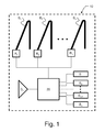
- inventions herein relate to a motor vehicle 30 safety arrangement 10, as schematically illustrated in figure 1 .
- the motor vehicle 30 safety arrangement 10 is provided for positioning a vehicle occupant properly relative to a back rest of a vehicle seat and restraining the vehicle occupant thus positioned on the vehicle seat in preparation of the vehicle 30 potentially being subject to a rear-end collision.
- the motor vehicle 30 has a respective safety belt B 1 , B 2 ...B n associated with each respective vehicle seat.
- a respective electric reversible safety belt retractor R 1 , R 2 ...R n is associated with each respective safety belt B 1 , B 2 ...B n .
- the motor vehicle 30 safety arrangement 10 comprises a rearward-looking detection system D 1 .
- the rearward-looking detection system D 1 is provided for detecting and classifying the collision risk for an approaching object, such as a vehicle approaching the motor vehicle 30 hosting the safety arrangement 10 from behind.
- the rearward-looking detection system D 1 suitably comprises processing means (not shown) arranged to perform the collision risk classification.
- the rearward-looking detection system D 1 comprises one or more of a Radio Detection And Ranging (RADAR) sensor, a Light Detection And Ranging (LIDAR) sensor, a Light Amplification by Stimulated Emission of Radiation (LASER) sensor, an ultrasound sensor, an infrared sensor, an image sensor, or any combination thereof.
- the image sensor may be a video sensor, designed as either a Charge-Coupled Device (CCD) camera or a Complementary Metal-Oxide Semiconductor (CMOS) camera, for example.
- CCD Charge-Coupled Device
- CMOS Complementary Metal-Oxide Semiconductor
- the rearward-looking detection system D 1 is arranged to estimate a time to collision and classify the collision risk for an approaching object as high when the estimated time to collision falls below a predetermined threshold.
- the safety arrangement 10 further comprises at least one sensor S 1 , S 2 ...S n , for monitoring one or more vehicle parameters.
- the at least one sensor S 1 , S 2 ...S n is arranged to monitor at least one of the following vehicle parameters: vehicle velocity, steering wheel angle, vehicle yaw rate, yawing acceleration, lateral acceleration, angle of inclination and wheel speeds.
- a control unit 20 is also comprised in the safety arrangement 10.
- the control unit 20 suitably comprises a processing unit, such as a computer processor, and appropriate software for controlling operation thereof.
- This control unit 20 is arranged to determine a driving state as critical or non-critical from the monitored vehicle parameters.
- the control unit 20 is arranged to determine critical driving from the monitored vehicle parameters when one or more of the vehicle parameters indicate: a low wheel to road friction coefficient, significant vehicle deceleration, vehicle lane change or strong vehicle turning.
- control unit 20 is arranged to determine a low wheel to road friction based on at least differences in the monitored wheel speeds.
- control unit 20 is arranged to determine significant vehicle deceleration based on at least a reduction of the monitored vehicle velocity exceeding a predetermined threshold during a predetermined time interval. This may e.g. be performed through the computer processor being arranged to continuously monitor the vehicle speed. If the vehicle speed reduces by more than X meters per second within a time interval of Y seconds, then a significant vehicle deceleration is detected.
- control unit 20 is arranged to determine vehicle lane change or strong vehicle turning based on at least one of the monitored steering wheel angle and vehicle yaw rate exceeding predetermined thresholds.
- the control unit 20 is further operable to control each electric reversible safety belt retractor R 1 , R 2 ...R n to apply a predetermined pullback force on each respective associated safety belt B 1 , B 2 ...B n , in order to pull an occupant into the vehicle seat in response to the collision risk for an approaching object being classified as high within a predetermined time of an indicated critical driving state.
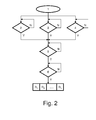
- FIG. 2 A schematic illustration of a method for positioning a vehicle 30 occupant properly relative to a back rest of a vehicle seat and restraining the occupant thus positioned on the vehicle seat in preparation of the vehicle 30 potentially being subject to a rear-end collision is schematically illustrated in figure 2 .
- the method is applicable to a vehicle 30 having a respective safety belt B 1 , B 2 ...B n associated with a respective vehicle seat and a respective electric reversible safety belt retractor R 1 , R 2 ... R n associated with each respective safety belt B 1 , B 2 ... B n .
- the method is initiated as a first step 1.
- the method comprises steps 2, 3, 4 of monitoring one or more vehicle parameters using at least one sensor S 1 , S 2 ...S n .
- figure 2 illustrates an embodiment where in step 2 is decided if a low wheel to road friction coefficient is present, in step 3 is decided if significant vehicle deceleration has occurred and in step 4 is decided if vehicle lane change or strong vehicle turning has occurred, where all of the above is decided from the monitored vehicle parameters.
- the method comprises arranging the at least one sensor S 1 , S 2 ...S n to monitor at least one of the following vehicle parameters: vehicle velocity, steering wheel angle, vehicle yaw rate, yawing acceleration, lateral acceleration, angle of inclination and wheel speeds.
- a step 5 of detecting and classifying the collision risk for an approaching object is performed using a rearward-looking detection system D 1 .
- the method comprises arranging to the rearward-looking detection system D 1 one or more of a radar sensor, a laser sensor, a lidar sensor, an ultrasound sensor, an infrared sensor, an image sensor, or any combination thereof.
- the method further comprises arranging the rearward-looking detection system D 1 to estimate a time to collision and classify the collision risk for an approaching object as high when the estimated time to collision falls below a predetermined threshold.
- a further step 6 of determining a driving state as critical or non-critical from the monitored vehicle parameters and controlling the electric reversible safety belt retractor R 1 , R 2 ...R n to apply a predetermined pullback force on the safety belt B 1 , B 2 ...B n to pull an occupant into the vehicle seat in response to the collision risk for an approaching object being classified as high within a predetermined time of an indicated critical driving state is performed using a control unit 20.
- the method further comprises arranging the control unit 20 to determine critical driving from the monitored vehicle parameters when one or more of the vehicle parameters indicate: a low wheel to road friction coefficient, significant vehicle deceleration, vehicle lane change or strong vehicle turning.
- the method also comprises arranging the control unit 20 to determine a low wheel to road friction coefficient based on at least differences in the monitored wheel speeds.
- the method further comprises arranging the control unit 20 to determine significant vehicle deceleration based on at least a reduction of the monitored vehicle velocity exceeding a predetermined threshold during a predetermined time interval.
- the method further comprises arranging the control unit 20 to determine vehicle lane change or strong vehicle turning based on at least one of the monitored steering wheel angle and vehicle yaw rate exceeding predetermined thresholds.
- a motor vehicle 30 that comprises a motor vehicle safety arrangement 10 as described herein.
Priority Applications (3)
| Application Number | Priority Date | Filing Date | Title |
|---|---|---|---|
| EP13151989.4A EP2756992A1 (de) | 2013-01-21 | 2013-01-21 | Kraftfahrzeugsicherheitsanordnung und Verfahren |
| CN201410016225.6A CN103935319A (zh) | 2013-01-21 | 2014-01-14 | 机动车安全设备和方法 |
| US14/154,491 US9545896B2 (en) | 2013-01-21 | 2014-01-14 | Motor vehicle safety arrangement and method |
Applications Claiming Priority (1)
| Application Number | Priority Date | Filing Date | Title |
|---|---|---|---|
| EP13151989.4A EP2756992A1 (de) | 2013-01-21 | 2013-01-21 | Kraftfahrzeugsicherheitsanordnung und Verfahren |
Publications (1)
| Publication Number | Publication Date |
|---|---|
| EP2756992A1 true EP2756992A1 (de) | 2014-07-23 |
Family
ID=47603384
Family Applications (1)
| Application Number | Title | Priority Date | Filing Date |
|---|---|---|---|
| EP13151989.4A Ceased EP2756992A1 (de) | 2013-01-21 | 2013-01-21 | Kraftfahrzeugsicherheitsanordnung und Verfahren |
Country Status (3)
| Country | Link |
|---|---|
| US (1) | US9545896B2 (de) |
| EP (1) | EP2756992A1 (de) |
| CN (1) | CN103935319A (de) |
Cited By (2)
| Publication number | Priority date | Publication date | Assignee | Title |
|---|---|---|---|---|
| WO2016024899A1 (en) * | 2014-08-13 | 2016-02-18 | Scania Cv Ab | System and method for safety improvement during operation of a motor vehicle |
| CN111098762A (zh) * | 2018-10-26 | 2020-05-05 | 现代自动车株式会社 | 预先主动安全调节控制方法及装置 |
Families Citing this family (4)
| Publication number | Priority date | Publication date | Assignee | Title |
|---|---|---|---|---|
| US9963251B2 (en) * | 2015-05-27 | 2018-05-08 | The Aerospace Corporation | Systems and methods for estimating parameters of a spacecraft based on emission from an atomic or molecular product of a plume from the spacecraft |
| EP3260344B1 (de) * | 2016-06-20 | 2021-10-06 | Volvo Car Corporation | Verfahren und system zur einstellung einer sicherheitsspannenschwelle einer fahrerunterstützungsfunktion |
| CN110780602B (zh) * | 2019-09-09 | 2022-02-18 | 腾讯科技(深圳)有限公司 | 一种仿真车辆换道轨迹的构建方法、装置及设备 |
| CN113200014A (zh) * | 2021-05-21 | 2021-08-03 | 上汽通用五菱汽车股份有限公司 | 安全带提示方法、车辆及可读存储介质 |
Citations (5)
| Publication number | Priority date | Publication date | Assignee | Title |
|---|---|---|---|---|
| US20020105416A1 (en) * | 2001-02-06 | 2002-08-08 | Haruhisa Kore | Occupant protection system for vehicle |
| US6758495B2 (en) | 2000-02-04 | 2004-07-06 | Daimlerchrysler Ag | Method and safety restraint device for restraining an occupant on a vehicle seat |
| EP1783007A1 (de) * | 2005-11-02 | 2007-05-09 | Robert Bosch Gmbh | Verfahren und Vorrichtung zur Aktivierung von Insassenschutzsystemen |
| WO2008002756A2 (en) | 2006-06-27 | 2008-01-03 | Gm Global Tecgnology Operations, Inc. | Rear collision warning system |
| JP2008120228A (ja) * | 2006-11-10 | 2008-05-29 | Toyota Motor Corp | 後突予測装置 |
Family Cites Families (3)
| Publication number | Priority date | Publication date | Assignee | Title |
|---|---|---|---|---|
| DE102004038167B4 (de) * | 2004-08-06 | 2013-03-07 | Daimler Ag | Kraftfahrzeug mit einem präventiv wirkenden Schutzsystem |
| WO2011114442A1 (ja) * | 2010-03-16 | 2011-09-22 | トヨタ自動車株式会社 | 運転支援装置 |
| US8855866B2 (en) * | 2011-11-22 | 2014-10-07 | Continental Automotive Systems, Inc. | Rear end advanced collision technology |
-
2013
- 2013-01-21 EP EP13151989.4A patent/EP2756992A1/de not_active Ceased
-
2014
- 2014-01-14 CN CN201410016225.6A patent/CN103935319A/zh active Pending
- 2014-01-14 US US14/154,491 patent/US9545896B2/en active Active
Patent Citations (5)
| Publication number | Priority date | Publication date | Assignee | Title |
|---|---|---|---|---|
| US6758495B2 (en) | 2000-02-04 | 2004-07-06 | Daimlerchrysler Ag | Method and safety restraint device for restraining an occupant on a vehicle seat |
| US20020105416A1 (en) * | 2001-02-06 | 2002-08-08 | Haruhisa Kore | Occupant protection system for vehicle |
| EP1783007A1 (de) * | 2005-11-02 | 2007-05-09 | Robert Bosch Gmbh | Verfahren und Vorrichtung zur Aktivierung von Insassenschutzsystemen |
| WO2008002756A2 (en) | 2006-06-27 | 2008-01-03 | Gm Global Tecgnology Operations, Inc. | Rear collision warning system |
| JP2008120228A (ja) * | 2006-11-10 | 2008-05-29 | Toyota Motor Corp | 後突予測装置 |
Cited By (3)
| Publication number | Priority date | Publication date | Assignee | Title |
|---|---|---|---|---|
| WO2016024899A1 (en) * | 2014-08-13 | 2016-02-18 | Scania Cv Ab | System and method for safety improvement during operation of a motor vehicle |
| US10315560B2 (en) | 2014-08-13 | 2019-06-11 | Scania Cv Ab | System and method for safety improvement during operation of a motor vehicle |
| CN111098762A (zh) * | 2018-10-26 | 2020-05-05 | 现代自动车株式会社 | 预先主动安全调节控制方法及装置 |
Also Published As
| Publication number | Publication date |
|---|---|
| US20140207339A1 (en) | 2014-07-24 |
| CN103935319A (zh) | 2014-07-23 |
| US9545896B2 (en) | 2017-01-17 |
Similar Documents
| Publication | Publication Date | Title |
|---|---|---|
| EP2484573B1 (de) | Verfahren zur Verringerung des Risikos eines Zusammenpralls zwischen einem Fahrzeug und einem ersten externen Objekt | |
| US9545896B2 (en) | Motor vehicle safety arrangement and method | |
| CN104960509B (zh) | 用于基于碰撞置信度最小化自动制动侵扰的方法 | |
| CN108357492B (zh) | 用于减轻道路车辆之间前向碰撞的设备和方法 | |
| CN107010059B (zh) | 用于确定车辆即将发生碰撞的概率的控制系统和控制方法 | |
| US10625735B2 (en) | Vehicle control apparatus and vehicle control method | |
| US8150583B2 (en) | Method and apparatus for avoiding or mitigating vehicle collisions | |
| EP2682318B1 (de) | Motorfahrzeugkollisionswarnsystem | |
| EP2913234B1 (de) | Automatische Bremsung bei Rückwärtsfahren | |
| EP2266022B1 (de) | Strassendetektionssystem mit erweiterter sicht | |
| JP4942642B2 (ja) | 車両における安全手段を制御するための方法と構成 | |
| EP3501911A1 (de) | Vorrichtung und verfahren zur steuerung eines aktiven fahrzeugsitzgurtes | |
| US8855866B2 (en) | Rear end advanced collision technology | |
| JP6983915B2 (ja) | 後方プリクラッシュセーフティシステム | |
| EP2883743B1 (de) | Vorrichtung und Verfahren für Fahrzeuginsassenschutz beim Abkommen von der Straße | |
| US20170151937A1 (en) | Vehicle control apparatus | |
| EP2743144A2 (de) | GPS-Daten zur Verbesserung von Fußgängerschutz | |
| KR100666360B1 (ko) | 차량 동역학에 근거한 충돌예방 안전장치 | |
| US11912127B2 (en) | Method for controlling a vehicle | |
| JP2007168697A (ja) | 乗員保護装置及び乗員保護方法 | |
| KR101511862B1 (ko) | 에어백 전개 기능을 포함한 자동 비상 제동 장치 및 그 제어방법 | |
| EP2650177B1 (de) | Verfahren zum Auslösen eines motorisierten Einzugs für ein Sicherheitsgurtsystem eines Fahrzeugs | |
| KR20230072569A (ko) | 차량 승객 사고 방지 시스템 및 그 제어 방법 | |
| KR20160054927A (ko) | 단계적 충돌 방지 시스템 | |
| CN115703463A (zh) | 用于控制车辆的装置和方法 |
Legal Events
| Date | Code | Title | Description |
|---|---|---|---|
| PUAI | Public reference made under article 153(3) epc to a published international application that has entered the european phase |
Free format text: ORIGINAL CODE: 0009012 |
|
| 17P | Request for examination filed |
Effective date: 20130121 |
|
| AK | Designated contracting states |
Kind code of ref document: A1 Designated state(s): AL AT BE BG CH CY CZ DE DK EE ES FI FR GB GR HR HU IE IS IT LI LT LU LV MC MK MT NL NO PL PT RO RS SE SI SK SM TR |
|
| AX | Request for extension of the european patent |
Extension state: BA ME |
|
| R17P | Request for examination filed (corrected) |
Effective date: 20150123 |
|
| RBV | Designated contracting states (corrected) |
Designated state(s): AL AT BE BG CH CY CZ DE DK EE ES FI FR GB GR HR HU IE IS IT LI LT LU LV MC MK MT NL NO PL PT RO RS SE SI SK SM TR |
|
| STAA | Information on the status of an ep patent application or granted ep patent |
Free format text: STATUS: THE APPLICATION HAS BEEN REFUSED |
|
| 18R | Application refused |
Effective date: 20181126 |