EP2756919A1 - Machine tool pallet changer, changing method and machine tool - Google Patents
Machine tool pallet changer, changing method and machine tool Download PDFInfo
- Publication number
- EP2756919A1 EP2756919A1 EP11872376.6A EP11872376A EP2756919A1 EP 2756919 A1 EP2756919 A1 EP 2756919A1 EP 11872376 A EP11872376 A EP 11872376A EP 2756919 A1 EP2756919 A1 EP 2756919A1
- Authority
- EP
- European Patent Office
- Prior art keywords
- pallet
- arm
- changing
- axis
- traverser
- Prior art date
- Legal status (The legal status is an assumption and is not a legal conclusion. Google has not performed a legal analysis and makes no representation as to the accuracy of the status listed.)
- Granted
Links
Images


Classifications
-
- B—PERFORMING OPERATIONS; TRANSPORTING
- B23—MACHINE TOOLS; METAL-WORKING NOT OTHERWISE PROVIDED FOR
- B23Q—DETAILS, COMPONENTS, OR ACCESSORIES FOR MACHINE TOOLS, e.g. ARRANGEMENTS FOR COPYING OR CONTROLLING; MACHINE TOOLS IN GENERAL CHARACTERISED BY THE CONSTRUCTION OF PARTICULAR DETAILS OR COMPONENTS; COMBINATIONS OR ASSOCIATIONS OF METAL-WORKING MACHINES, NOT DIRECTED TO A PARTICULAR RESULT
- B23Q1/00—Members which are comprised in the general build-up of a form of machine, particularly relatively large fixed members
- B23Q1/25—Movable or adjustable work or tool supports
- B23Q1/64—Movable or adjustable work or tool supports characterised by the purpose of the movement
- B23Q1/66—Worktables interchangeably movable into operating positions
-
- B—PERFORMING OPERATIONS; TRANSPORTING
- B23—MACHINE TOOLS; METAL-WORKING NOT OTHERWISE PROVIDED FOR
- B23Q—DETAILS, COMPONENTS, OR ACCESSORIES FOR MACHINE TOOLS, e.g. ARRANGEMENTS FOR COPYING OR CONTROLLING; MACHINE TOOLS IN GENERAL CHARACTERISED BY THE CONSTRUCTION OF PARTICULAR DETAILS OR COMPONENTS; COMBINATIONS OR ASSOCIATIONS OF METAL-WORKING MACHINES, NOT DIRECTED TO A PARTICULAR RESULT
- B23Q1/00—Members which are comprised in the general build-up of a form of machine, particularly relatively large fixed members
- B23Q1/25—Movable or adjustable work or tool supports
- B23Q1/44—Movable or adjustable work or tool supports using particular mechanisms
- B23Q1/50—Movable or adjustable work or tool supports using particular mechanisms with rotating pairs only, the rotating pairs being the first two elements of the mechanism
- B23Q1/54—Movable or adjustable work or tool supports using particular mechanisms with rotating pairs only, the rotating pairs being the first two elements of the mechanism two rotating pairs only
-
- B—PERFORMING OPERATIONS; TRANSPORTING
- B23—MACHINE TOOLS; METAL-WORKING NOT OTHERWISE PROVIDED FOR
- B23Q—DETAILS, COMPONENTS, OR ACCESSORIES FOR MACHINE TOOLS, e.g. ARRANGEMENTS FOR COPYING OR CONTROLLING; MACHINE TOOLS IN GENERAL CHARACTERISED BY THE CONSTRUCTION OF PARTICULAR DETAILS OR COMPONENTS; COMBINATIONS OR ASSOCIATIONS OF METAL-WORKING MACHINES, NOT DIRECTED TO A PARTICULAR RESULT
- B23Q7/00—Arrangements for handling work specially combined with or arranged in, or specially adapted for use in connection with, machine tools, e.g. for conveying, loading, positioning, discharging, sorting
- B23Q7/04—Arrangements for handling work specially combined with or arranged in, or specially adapted for use in connection with, machine tools, e.g. for conveying, loading, positioning, discharging, sorting by means of grippers
-
- B—PERFORMING OPERATIONS; TRANSPORTING
- B23—MACHINE TOOLS; METAL-WORKING NOT OTHERWISE PROVIDED FOR
- B23Q—DETAILS, COMPONENTS, OR ACCESSORIES FOR MACHINE TOOLS, e.g. ARRANGEMENTS FOR COPYING OR CONTROLLING; MACHINE TOOLS IN GENERAL CHARACTERISED BY THE CONSTRUCTION OF PARTICULAR DETAILS OR COMPONENTS; COMBINATIONS OR ASSOCIATIONS OF METAL-WORKING MACHINES, NOT DIRECTED TO A PARTICULAR RESULT
- B23Q7/00—Arrangements for handling work specially combined with or arranged in, or specially adapted for use in connection with, machine tools, e.g. for conveying, loading, positioning, discharging, sorting
- B23Q7/04—Arrangements for handling work specially combined with or arranged in, or specially adapted for use in connection with, machine tools, e.g. for conveying, loading, positioning, discharging, sorting by means of grippers
- B23Q7/043—Construction of the grippers
-
- B—PERFORMING OPERATIONS; TRANSPORTING
- B23—MACHINE TOOLS; METAL-WORKING NOT OTHERWISE PROVIDED FOR
- B23Q—DETAILS, COMPONENTS, OR ACCESSORIES FOR MACHINE TOOLS, e.g. ARRANGEMENTS FOR COPYING OR CONTROLLING; MACHINE TOOLS IN GENERAL CHARACTERISED BY THE CONSTRUCTION OF PARTICULAR DETAILS OR COMPONENTS; COMBINATIONS OR ASSOCIATIONS OF METAL-WORKING MACHINES, NOT DIRECTED TO A PARTICULAR RESULT
- B23Q7/00—Arrangements for handling work specially combined with or arranged in, or specially adapted for use in connection with, machine tools, e.g. for conveying, loading, positioning, discharging, sorting
- B23Q7/04—Arrangements for handling work specially combined with or arranged in, or specially adapted for use in connection with, machine tools, e.g. for conveying, loading, positioning, discharging, sorting by means of grippers
- B23Q7/048—Multiple gripper units
-
- B—PERFORMING OPERATIONS; TRANSPORTING
- B23—MACHINE TOOLS; METAL-WORKING NOT OTHERWISE PROVIDED FOR
- B23Q—DETAILS, COMPONENTS, OR ACCESSORIES FOR MACHINE TOOLS, e.g. ARRANGEMENTS FOR COPYING OR CONTROLLING; MACHINE TOOLS IN GENERAL CHARACTERISED BY THE CONSTRUCTION OF PARTICULAR DETAILS OR COMPONENTS; COMBINATIONS OR ASSOCIATIONS OF METAL-WORKING MACHINES, NOT DIRECTED TO A PARTICULAR RESULT
- B23Q7/00—Arrangements for handling work specially combined with or arranged in, or specially adapted for use in connection with, machine tools, e.g. for conveying, loading, positioning, discharging, sorting
- B23Q7/14—Arrangements for handling work specially combined with or arranged in, or specially adapted for use in connection with, machine tools, e.g. for conveying, loading, positioning, discharging, sorting co-ordinated in production lines
- B23Q7/1426—Arrangements for handling work specially combined with or arranged in, or specially adapted for use in connection with, machine tools, e.g. for conveying, loading, positioning, discharging, sorting co-ordinated in production lines with work holders not rigidly fixed to the transport devices
- B23Q7/1431—Work holder changers
-
- B—PERFORMING OPERATIONS; TRANSPORTING
- B23—MACHINE TOOLS; METAL-WORKING NOT OTHERWISE PROVIDED FOR
- B23Q—DETAILS, COMPONENTS, OR ACCESSORIES FOR MACHINE TOOLS, e.g. ARRANGEMENTS FOR COPYING OR CONTROLLING; MACHINE TOOLS IN GENERAL CHARACTERISED BY THE CONSTRUCTION OF PARTICULAR DETAILS OR COMPONENTS; COMBINATIONS OR ASSOCIATIONS OF METAL-WORKING MACHINES, NOT DIRECTED TO A PARTICULAR RESULT
- B23Q7/00—Arrangements for handling work specially combined with or arranged in, or specially adapted for use in connection with, machine tools, e.g. for conveying, loading, positioning, discharging, sorting
- B23Q7/14—Arrangements for handling work specially combined with or arranged in, or specially adapted for use in connection with, machine tools, e.g. for conveying, loading, positioning, discharging, sorting co-ordinated in production lines
- B23Q7/1426—Arrangements for handling work specially combined with or arranged in, or specially adapted for use in connection with, machine tools, e.g. for conveying, loading, positioning, discharging, sorting co-ordinated in production lines with work holders not rigidly fixed to the transport devices
- B23Q7/1494—Arrangements for handling work specially combined with or arranged in, or specially adapted for use in connection with, machine tools, e.g. for conveying, loading, positioning, discharging, sorting co-ordinated in production lines with work holders not rigidly fixed to the transport devices using grippers
-
- B—PERFORMING OPERATIONS; TRANSPORTING
- B65—CONVEYING; PACKING; STORING; HANDLING THIN OR FILAMENTARY MATERIAL
- B65G—TRANSPORT OR STORAGE DEVICES, e.g. CONVEYORS FOR LOADING OR TIPPING, SHOP CONVEYOR SYSTEMS OR PNEUMATIC TUBE CONVEYORS
- B65G25/00—Conveyors comprising a cyclically-moving, e.g. reciprocating, carrier or impeller which is disengaged from the load during the return part of its movement
- B65G25/04—Conveyors comprising a cyclically-moving, e.g. reciprocating, carrier or impeller which is disengaged from the load during the return part of its movement the carrier or impeller having identical forward and return paths of movement, e.g. reciprocating conveyors
-
- Y—GENERAL TAGGING OF NEW TECHNOLOGICAL DEVELOPMENTS; GENERAL TAGGING OF CROSS-SECTIONAL TECHNOLOGIES SPANNING OVER SEVERAL SECTIONS OF THE IPC; TECHNICAL SUBJECTS COVERED BY FORMER USPC CROSS-REFERENCE ART COLLECTIONS [XRACs] AND DIGESTS
- Y10—TECHNICAL SUBJECTS COVERED BY FORMER USPC
- Y10T—TECHNICAL SUBJECTS COVERED BY FORMER US CLASSIFICATION
- Y10T29/00—Metal working
- Y10T29/51—Plural diverse manufacturing apparatus including means for metal shaping or assembling
- Y10T29/5124—Plural diverse manufacturing apparatus including means for metal shaping or assembling with means to feed work intermittently from one tool station to another
-
- Y—GENERAL TAGGING OF NEW TECHNOLOGICAL DEVELOPMENTS; GENERAL TAGGING OF CROSS-SECTIONAL TECHNOLOGIES SPANNING OVER SEVERAL SECTIONS OF THE IPC; TECHNICAL SUBJECTS COVERED BY FORMER USPC CROSS-REFERENCE ART COLLECTIONS [XRACs] AND DIGESTS
- Y10—TECHNICAL SUBJECTS COVERED BY FORMER USPC
- Y10T—TECHNICAL SUBJECTS COVERED BY FORMER US CLASSIFICATION
- Y10T29/00—Metal working
- Y10T29/51—Plural diverse manufacturing apparatus including means for metal shaping or assembling
- Y10T29/5176—Plural diverse manufacturing apparatus including means for metal shaping or assembling including machining means
-
- Y—GENERAL TAGGING OF NEW TECHNOLOGICAL DEVELOPMENTS; GENERAL TAGGING OF CROSS-SECTIONAL TECHNOLOGIES SPANNING OVER SEVERAL SECTIONS OF THE IPC; TECHNICAL SUBJECTS COVERED BY FORMER USPC CROSS-REFERENCE ART COLLECTIONS [XRACs] AND DIGESTS
- Y10—TECHNICAL SUBJECTS COVERED BY FORMER USPC
- Y10T—TECHNICAL SUBJECTS COVERED BY FORMER US CLASSIFICATION
- Y10T29/00—Metal working
- Y10T29/51—Plural diverse manufacturing apparatus including means for metal shaping or assembling
- Y10T29/5196—Multiple station with conveyor
-
- Y—GENERAL TAGGING OF NEW TECHNOLOGICAL DEVELOPMENTS; GENERAL TAGGING OF CROSS-SECTIONAL TECHNOLOGIES SPANNING OVER SEVERAL SECTIONS OF THE IPC; TECHNICAL SUBJECTS COVERED BY FORMER USPC CROSS-REFERENCE ART COLLECTIONS [XRACs] AND DIGESTS
- Y10—TECHNICAL SUBJECTS COVERED BY FORMER USPC
- Y10T—TECHNICAL SUBJECTS COVERED BY FORMER US CLASSIFICATION
- Y10T409/00—Gear cutting, milling, or planing
- Y10T409/30—Milling
- Y10T409/304536—Milling including means to infeed work to cutter
- Y10T409/30532—Milling including means to infeed work to cutter with means to advance work or product
-
- Y—GENERAL TAGGING OF NEW TECHNOLOGICAL DEVELOPMENTS; GENERAL TAGGING OF CROSS-SECTIONAL TECHNOLOGIES SPANNING OVER SEVERAL SECTIONS OF THE IPC; TECHNICAL SUBJECTS COVERED BY FORMER USPC CROSS-REFERENCE ART COLLECTIONS [XRACs] AND DIGESTS
- Y10—TECHNICAL SUBJECTS COVERED BY FORMER USPC
- Y10T—TECHNICAL SUBJECTS COVERED BY FORMER US CLASSIFICATION
- Y10T409/00—Gear cutting, milling, or planing
- Y10T409/30—Milling
- Y10T409/306048—Milling with means to advance work or product
Definitions
- Patent Document 1 Japanese Unexamined Patent Publication No. H07-171730
- the pallet is attached to the pallet support by fitting a projection provided on the pallet support into a dovetail groove provided in the pallet.
- coupling a pallet and a pallet support by a projection and a dovetail groove as the pallet changer of Patent Document 1, has the problem that it takes relatively a long time to transport a pallet between the pallet support and a table of the machine tool. Further, it requires increased weight of the pallet and the arm member.
- the arm member when changing a non-processed workpiece and a processed workpiece with each other, the arm member must be horizontally (X-axis direction) reciprocated twice along with a heavy arm base, which further increases the time for changing the pallets.
- a pallet changer for changing pallets between a table to which a pallet is vertically mounted and a pallet loading station in which a pallet is held horizontally, comprising: a changing arm provided for rotation between the table and the pallet loading station about a rotational axis upwardly inclined relative to a horizontal axis by 45 degrees; and two arm portions, provided at the either end of the changing arm, for gripping gripped members, each of the gripped members being disposed on a side of the pallet, which side is positioned at a lower end of the pallet when the pallet is vertically oriented.
- a machine tool comprising: a spindle held for rotation about a horizontal rotational axis; a table, provided so as to be able to face the spindle, for mounting a vertically oriented pallet to which a workpiece is attached; means for linearly feeding the table and the spindle relative to each other along three orthogonal axes; means for rotationally feeding the table about a vertical axis; and a pallet loading station for attaching a non-processed workpiece to a horizontally held pallet and detaching a processed workpiece from the pallet; the machine tool further comprising a changing arm having first and second arm portions at either end thereof, and provided to grip one end of the pallets and rotate about a rotational axis upwardly inclined relative to a horizontal axis by 45 degrees between the table side position, where the changing arm faces to the table, and the pallet loading station, the one side becoming the lower end when the pallet is mounted to the table.
- the X-axis feed mechanism may include a pair of X-axis guide rails 102a horizontally extending in the left-right direction in the top face of the bed 102, guide blocks (not shown) mounted to a bottom face of the column 104 for sliding along the X-axis guide rails 102a, an X-axis ball screw (not shown) extending in the X-axis direction in the bed 102, a nut (not shown) mounted to the lower end portion of the column 104 so as to engage the X-axis ball screw and a servomotor, connected to an end of the X-axis ball screw, for driving the X-axis ball screw.
Landscapes
- Engineering & Computer Science (AREA)
- Mechanical Engineering (AREA)
- Feeding Of Workpieces (AREA)
Abstract
Description
- The invention relates to a pallet changer and a pallet changing method for changing a pallet vertically attached to a table with a pallet horizontally disposed at a pallet loading station, and to a machine tool provided with the pallet changer.
- In the field of machine tools, a workpiece is conventionally attached to a pallet which is detachably attached to a table of a machine tool whereby the workpiece is processed. In such machine tools, a non-processed workpiece and a processed workpiece, each attached to a pallet, are exchanged with each other by a pallet changer.
- Patent Document 1, for example, discloses a pallet changer which is provided with an arm member, rotatable about an axis inclined by 45 degrees relative to a horizontal plane. The arm member has a pair of pallet supports, symmetrically disposed relative to the inclined axis of the arm member, whereby the rotation of the arm member exchanges the pallet supports between a pallet changing position and a work changing position.
- Patent Document 1: Japanese Unexamined Patent Publication No.
H07-171730 - In the pallet changer described in Patent Document 1, the pallet is attached to the pallet support by fitting a projection provided on the pallet support into a dovetail groove provided in the pallet. However, coupling a pallet and a pallet support by a projection and a dovetail groove, as the pallet changer of Patent Document 1, has the problem that it takes relatively a long time to transport a pallet between the pallet support and a table of the machine tool. Further, it requires increased weight of the pallet and the arm member. Furthermore, in the pallet changer of Patent Document 1, when changing a non-processed workpiece and a processed workpiece with each other, the arm member must be horizontally (X-axis direction) reciprocated twice along with a heavy arm base, which further increases the time for changing the pallets.
- The invention is directed to solve the problems in the prior art, and the objective of the invention is to provide a pallet changer, a pallet changing method and a machine tool which can quickly change a pallet vertically attached to a table with a pallet horizontally disposed at a pallet loading station securely and quickly by a simple configuration and a compact movement. Further, the objective of the invention is to provide a pallet changer, a pallet changing method and a machine tool which allow use of light weight pallets in the form of flat and simple plates.
a rotary workhead device for a machine tool, which processes a workpiece under tensile or compressive force applied, improved to have a simple configuration whereby the production cost is reduced. - According to the invention, there is provided a pallet changer for changing pallets between a table to which a pallet is vertically mounted and a pallet loading station in which a pallet is held horizontally, comprising: a changing arm provided for rotation between the table and the pallet loading station about a rotational axis upwardly inclined relative to a horizontal axis by 45 degrees; and two arm portions, provided at the either end of the changing arm, for gripping gripped members, each of the gripped members being disposed on a side of the pallet, which side is positioned at a lower end of the pallet when the pallet is vertically oriented.
- Further, according to the invention, there is provided a pallet changing method of changing pallets between a table to which a pallet is vertically mounted and a pallet loading station in which a pallet is held horizontally, characterized by the steps of: gripping a lower end of the pallet mounted to the table by a first arm portion of a changing arm; gripping one side of the pallet which is positioned in the pallet loading station by a second arm portion of the changing arm, the one side becoming the lower end when the pallet is mounted to the table; and rotating the changing arm by 180 degrees about a rotational axis upwardly inclined relative to a horizontal axis by 45 degrees.
- Further, according to the invention, there is provided a machine tool, comprising: a spindle held for rotation about a horizontal rotational axis; a table, provided so as to be able to face the spindle, for mounting a vertically oriented pallet to which a workpiece is attached; means for linearly feeding the table and the spindle relative to each other along three orthogonal axes; means for rotationally feeding the table about a vertical axis; and a pallet loading station for attaching a non-processed workpiece to a horizontally held pallet and detaching a processed workpiece from the pallet;
the machine tool further comprising a changing arm having first and second arm portions at either end thereof, and provided to grip one end of the pallets and rotate about a rotational axis upwardly inclined relative to a horizontal axis by 45 degrees between the table side position, where the changing arm faces to the table, and the pallet loading station, the one side becoming the lower end when the pallet is mounted to the table. - According to the invention, during the rotational movement of the the changing arm, the gripped members of the pallets are biased against the arm portions by the gravity applied to the pallets, except when the pallet is horizontally oriented in the pallet loading station. Therefore, if the pallet changing operation is normally carried out, the pallets cannot be disengaged from the pallet gripping parts. Therefore, the pallet changing operation has a simple configuration, i.e., gripping one side of the pallets with the changing arm. The other functional operation and the advantageous effect of the present invention will be apparent from the description of the following mode for carrying out the invention.
-
-
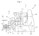
Figure 1 is a side view illustrating a machining center according to an embodiment of the invention. -
Figure 2 is a front view of a pallet changer in the direction of arrow II inFigure 1 . -
Figure 3 is a side view of the pallet changer in the direction of arrow III inFigure 1 , showing pallet A and a pallet holder. -
Figure 4 is a front view of the pallet changer in the direction of arrow IV inFigure 1 . -
Figure 5A is an enlarged view of a pallet gripping part of the pallet changer and a locking mechanism, showing a situation of the locking mechanism in which locking pins engage with a gripped member of the pallet. -
Figure 5B is an enlarged view of a pallet gripping part of the pallet changer and a locking mechanism, showing a situation of the locking mechanism in which locking pins disengage from a gripped member of the pallet. -
Figure 6 is a side view of the changing arm. -
Figure 7 is a sectional view of the changing arm shown with changing arm driving means. -
Figure 8 is a partially sectional view along line VIII-VIII inFigure 7 . -
Figure 9 is a plan view of the pallet changer in the direction of arrow IX inFigure 1 . -
Figure 10A is a flow chart explaining the pallet changing operation of the pallet changer. -
Figure 10A is a flow chart explaining the pallet changing operation of the pallet changer. - With reference to
Figures 1-10 , an embodiment of a machining center according to the invention will be described below. - With reference to
Figure 1 , amachine tool 100, provided with apallet changer 10 according the embodiment of the invention, is a horizontal machine tool comprising abed 102 adapted to be secured to a factory floor, acolumn 104 mounted to the top face of a rear part (the right side part inFigure 1 ) of thebed 102 for moving in the left-right direction (X-axis direction) by an X-axis feed mechanism, aspindle head 106 mounted to the front surface of thecolumn 104 for moving in the vertical direction (Y-axis direction) by a Y-axis feed mechanism and a B-axis base 110 mounted to the top face of a front part of thebed 102 for moving in the front-rear direction (Z-axis direction) by a Z-axis feed mechanism. Aspindle 108 is supported by the spindledhead 106 for rotation about a horizontal rotational axis Os. A tool T is attached to the end of thespindle 108. A B-axis table 112 is rotatably supported by the B-axis base 110 for angular range of ± 180 degrees about a vertical axis (B-axis). A servomotor (not shown) is incorporated as a B-axis feed mechanism in the B-axis base 110. - The X-axis feed mechanism may include a pair of
X-axis guide rails 102a horizontally extending in the left-right direction in the top face of thebed 102, guide blocks (not shown) mounted to a bottom face of thecolumn 104 for sliding along theX-axis guide rails 102a, an X-axis ball screw (not shown) extending in the X-axis direction in thebed 102, a nut (not shown) mounted to the lower end portion of thecolumn 104 so as to engage the X-axis ball screw and a servomotor, connected to an end of the X-axis ball screw, for driving the X-axis ball screw. - Similarly, the Y-axis feed mechanism may include a pair of Y-axis guide rails (not shown) vertically extending in the
column 104, guide blocks (not shown) mounted to thespindle head 106 for sliding along the Y-axis guide rails, a Y-axis ball screw (not shown) extending in the Y-axis direction in thecolumn 104, a nut (not shown) mounted in thespindle head 106 so as to engage the Y-axis ball screw and a servomotor, connected to an end of the Y-axis ball screw, for driving the Y-axis ball screw. - Similarly, the Z-axis feed mechanism may include a pair of Z-
axis guide rails 102b horizontally extending in the top face of thebed 102 perpendicular to theX-axis guide rails 102a, guide blocks (not shown) mounted to a bottom face of the B-axis base 110 for sliding along the Z-axis guide rails 102b, a Z-axis ball screw (not shown) extending in the Z-axis direction in thebed 102, a nut (not shown) mounted to a bottom face of the B-axis base 110 so as to engage the Z-axis ball screw and a servomotor, connected to an end of the Z-axis ball screw, for driving the Z-axis ball screw. - Secured to the top face of the B-axis table 112 is a C-
axis base 114, to which a C-axis table 116, having a vertical pallet mounting face, is mounted for rotation about a horizontally extending rotational axis, defining a C-axis. C-axis base 114 is incorporated with a servomotor (not shown) providing a C-axis feed mechanism for the C-axis table 116. A pallet A, to which a workpiece W is attached, is detachably secured to the pallet mounting face of the C-axis table 116. When the pallet A is secured to the pallet mounting face, a workpiece mounting face, defined by the pallet A, is aligned with the B-axis. The C-axis table 116 provides the table described in the claims. - Accordingly, the
machine tool 100 is a machine tool having five feed axes of three orthogonal liner feed axes, i.e., X-axis, Y-axis and Z-axis, and two rotational feed axes, i.e., B-axis and C-axis. As described below, a first pallet changing position is defined on the Z-axis by the position of the B-axis table 112 where a pallet A is removed from the C-axis table, and a second pallet changing position is defined on the Z-axis by the position of the B-axis table where a pallet B is mounted to the C-axis table 116. - The pallet changer (APC) 10 comprises an APC base 12 (corresponding to the base of claim 6) which is secured to the front part (the left side part in
Figure 1 ) of thebed 102, a pallet loading station (PLS) 14, a changingarm 16 mounted to theAPC base 12 for rotation about an inclined rotation axis O and for moving in the vertical direction and atraverser 18 for transporting the pallet A between the changingarm 16 and the C-axis table 116. The changingarm 16 is formed into substantially an L shape having twoarm portions pallet gripping parts 17 and a palletengaging mechanism 50 are provided on each of thearm portions spindle 108, upwardly from a horizontal axis by 45 degrees. - In the
pallet loading station 14, a PLS table 130 reciprocally movable in the Z-axis, ahydraulic cylinder 132 providing means for moving the PLS table 130, apallet mount 134 mounted to the PLS table 130 for rotation about a vertical axis Op, and anindex pin 136 for locking thepallet mount 134 relative to the PLS table at a desired rotational position. The PLS table 130 is reciprocally movable between a preparation position shown by a pallet indicated by dash and dot line inFigure 9 and a third pallet changing position shown by another pallet indicated by solid line. At the preparation position, an operator of themachining center 100 removes a processed workpiece from the pallet A and attaches a non-processed workpiece to the pallet B. At the third pallet changing position, the pallet B can be engaged with thesecond arm portion 16b of the changingarm 16, as described below. - With reference to
Figures 2 and 3 , thepallet 118, to which a workpiece W is attached, comprises a body defining aworkpiece attachment face 120a for attaching the workpiece W, agripped member 122 laterally extending from one side of thebody 120 and adapted to be engaged by the changingarm 16, aheld member 124 laterally and outwardly extending further from thegripped member 122 and adapted to be engaged by apallet holder 36 of thetraverser 18, andpull studs 126 extending from the face of thebody 120 opposite to theworkpiece attachment face 120a and adapted to be engaged by a clamper (not shown) provided on the C-axis table 116. The pallet A is a pallet to which a processed workpiece W is attached and the pallet B is a pallet to which a non-processed workpiece W is attached. - The
traverser 18 comprises first andsecond sliders APC base 12, andhydraulic cylinder 24 providing an actuator for driving the first andsecond sliders first slider 20 is slidable alongfirst rails 26 secured to the top face of the traverser base and extending in the Z-axis. Thesecond slider 22 is slidable alongsecond rails 28 secured to a top face of thefirst slider 20 and extending in the Z-axis. Afirst rack 30, extending in the Z-axis, is secured to the top face of the traverser. Thefirst slider 20 has apinion 32 engaging with therack 30. Secured to a bottom face of thesecond slider 22 is asecond rack 34 which also engages thepinion 32. - Disposed at the distal end of the
second slider 22 are apallet holder 36 which is vertically movable relative to thesecond slider 22 in order to engage with and disengage from theholder member 124 of thepallet 118, ahydraulic cylinder 39 for lifting and lowering thepallet holder 36 relative to thesecond slider 22, and avertical guide 38 for guiding the lifting and lowering movement of thepallet holder 36. Thepallet holder 36 is further provided with a plurality of holdingpins member 124 of thepallet 118. The pallet holding pins 40 and 42 are offset from each other in the Z-axis direction, as shown in this embodiment, so that the pallet holding pins 40, located outside inFigure 2 , engage with the back side of the heldmember 124, while the pallet holding pins 42, located inside, engage the front side of the heldmember 124. Therefore, thepallet 118 is held by thepallet holder 36 by inserting the heldmember 124 between the pallet holding pins 40 and pallet holding pins 42. - With reference to
Figures 5A and5B , at the distal end of the eacharm portions pallet gripping parts 17 is provided for gripping thepallet 118 by engaging with the grippedmember 122. The grippedmember 122 is provided withfitting portions 122a complementary to thepallet gripping parts 17. As shown inFigures 4 and9 , thefitting portions 122a disposed at the either end of the grippedmember 122 is adapted to fit into C-shaped grooves defined in thepallet gripping parts 17. Further,pallet locking mechanisms 50, for preventing the grippedmember 122 from disengage from the pallet gripped members, are disposed outside each of thepallet gripping parts 17. - The
pallet locking mechanisms 50 comprise, as main elements,plungers 52, locking pins 54 andlinks 56 for operatively connecting theplungers 52 and the locking pins 54. On the side walls of theAPC base 12,first dogs 64, which are adapted to be abutted by theplungers 52 when thearm portions arm 16 are positioned at machine side position where they face the C-axis base 114, and second gods which are adapted to be abutted by theplungers 52 when thearm portions arm 16 are positioned in the pallet loading station. Thesecond dogs 78 have aninclined face 78a. - The
plungers 52 are reciprocably held bybrackets 58 mounted to the sides of thearm portions arm 16 at the distal ends thereof. Theplungers 52 haverollers 52a mounted at their ends facing thefirst dogs 64, pins 52b disposed at the opposite ends so as to engageslots 56a of thelinks 56 andcoil springs 65 disposed around theplungers 52 for biasing theplungers 52 toward thefirst dogs 64. - The locking pins are oriented substantially perpendicular to the
plungers 52 within lockingpin holes 16c formed in thearm portions locking pin holes 16c so that theirend portions 54a can engage with and disengage from engaging holes formed in the sides of the grippedmember 122 of thepallet 118. At the rear ends of the locking pins 54, pins 54b are provided to engageslots 56b of thelinks 54. Thelinks 56 define the slots 65a engaging thepins 52b of theplungers 52 and theslots 56b engaging thepins 54b of the locking pins 54, and are mounted to thebrackets 58 for rotation about pivots defined by pins 60. Therefore, thepallet locking mechanisms 50 are preferably enclosed by covers 80. - With reference to
Figures 6 and7 , the changingarm 16 has thearm portions arm portions sleeve portion 62 is rotatably mounted to acam base 74. Thecam base 74 has avertical guide 66 disposed within aguide hole 12a defined in theAPC base 12 whereby the cam base is mounted to theAPC base 12 for lifting and lowering motion in the Y-axis direction by ahydraulic cylinder 68 providing lifting and lowering means. - Provided within the
sleeve portion 62 is acylindrical cam 70 which provides rotation means for rotating the changingarm 16. Ahydraulic cylinder 72, providing cam driving means for reciprocating thecylindrical cam 70 along the rotation axis O within thesleeve portion 62, is mounted to thecam base 74. At least onecam groove 70a is provided in the outer surface of thecylindrical cam 70, while at least onecam follower 76, engaging thecam groove 74, is disposed in the inside surface of the sleeve portion. Accordingly, the liner motion of thehydraulic cylinder 72 is converted into the rotation of the changingarm 16. - With reference to flow charts, illustrating the pallet changing operation of the pallet changer, shown in
Figures 10A and10B , the functional operation of the pallet changer of the present embodiment will be described below. - When the
machining center 100 complete the process on the workpiece W, the B-axis base 110 moves apart from thecolumn 104 in the Z-axis direction to the first pallet changing position (step S1). The B-axis table rotates so that the pallet A, mounted to the C-axis table 116, faces opposite to the spindle 108 (step S2). The C-axis table 116 rotates to the home position so as to orient the heldmember 124 of the pallet A down (step S3). - The
traverser 18 extends so as to position the pallet holder 46 under the held member 124 (step S4). Thehydraulic cylinder 39 of thepallet holder 36 lifts thepallet holder 36 so as to insert the heldmember 124 between the pallet holding pins 40 and pallet holding pins 42 whereby the pallet A is held (step S5). The pallet A is unclamped by disengaging the clamper of the C-axis table 116 (step S6). Thetraverser 18 is retracted with the pallet A is held by thepallet holder 36 so as to move the pallet A toward thearm portion 16a. Then, thehydraulic cylinder 39 moves thepallet holder 36 downwardly whereby the grippedmember 122 of the pallet A is fitted with thepallet gripping parts 17. At the same time, the PLS table 130 with the pallet B mounted, to which a non-processed workpiece is attached, moves toward the changingarm 16 to the third changing position whereby the grippedmember 122 is fitted with thepallet gripping parts 17 of thearm portion 16b of the changingarm 16, the arm portion being positioned in the pallet loading station (step S8). - Then, the
hydraulic cylinder 68 lifts thecam base 74. Accordingly, the changingarm 16 moves upwardly so that theplunders 52 of the lockingmechanisms 50 of thearm portion 16a at the machine side position move apart from thefirst dogs 64 whereby the locking pins 54 engage the grippedmember 122. At the same time, theplunger 52 of the lockingmechanisms 50 of thearm portion 16, in thepallet loading station 14, move along theinclined face 78a and apart from thesecond dogs 78 whereby the locking pins 54 engage the grippedmember 122 of the pallet B (step S9). - By linearly moving the
cylindrical cam 70 along the inclined rotation axis O with thehydraulic cylinder 72, the changingarm 16 is rotated by 180 degrees about the inclined rotation axis O by the engagement between thecam groove 70a of thecylindrical cam 70 and thecam follower 76, whereby the pallet A and pallet B are exchanged with each other (step S10). Meanwhile, the grippedmembers 122 of the pallets A and B are biased against thearm portions pallet loading station 14. Therefore, according to the present embodiment, the pallets A and B cannot be disengaged from thepallet gripping parts 17 even if the engagement between the locking pins 54 of the lockingmechanisms 50 and the grippedmembers 122 is insufficient for some reason. - Then, the
hydraulic cylinder 68 moves downwardly thecam base 74 along with the changingarm 16 so that theplungers 52 of thearm portion 16 abut thefirst dogs 64 whereby the locking pins 54 move apart the grippedmember 122 of the pallet B, while at the same time theplungers 52 of thearm portion 16b move along theinclined face 78a whereby the locking pins 54 move apart from the grippedmember 122 of the pallet A (step S11). - The
hydraulic cylinder 39 of thetraverser 18 lifts thepallet holder 36 whereby the heldmember 124 of the pallet B is held by thepallet holder 36. At the same time, in thepallet loading station 14, thehydraulic cylinder 132 moves the PLS table 130, with the pallet A mounted thereto, from the third pallet changing position to the preparation position (step S12). At the preparation station, an operator of themachining center 100 detaches the processed workpiece from the pallet A in exchange with a non-processed workpiece. - Then, the B-
axis base 110 is moved in the Z-axis direction slightly, for example 1mm, from the first pallet changing position toward the changingarm 16 to the second pallet changing position (step S13). Then, thetraverser 18 extends so that the pallet B with the non-processed workpiece attached thereto is moved to the C-axis table 116 (step S14). By engaging the clamper (not shown) of the C-axis table 116, the pallet B is clamped to the C-axis table 116 (step S15). Then, thepallet holder 36 of thetraverser 18 moves downwardly (step S16), and thetraverser 18 returns to the changingarm 16 side whereby the sequence of the pallet changing operation is completed. - In relation to step S13, in the present invention, the upper end of the pallet B will leans slightly toward the changing
arm 16, because thepallet holder 36 holds the heldmember 124 of the pallet B by inserting it betweenpallet holding pins 40 and the pallet holding pins 42. Therefore, at the first pallet changing position (theoretical position on the Z-axis where the pallet holder can hold the pallet A with the maximum extension of the traverser 18), insufficient clamp may result because thepull studs 126 are not fully inserted into the clamper due to a small gap formed between the pallet B and the C-axis table 116. Therefore, in step S13, by moving slightly the B-axis base 110 toward the changingarm 16 to the second pallet changing position along the Z-axis, thetraverser 18 pushes the pallet B to the C-axis by a small distance, for example 1mm, so that the formation of gap between the pallet B and the C-axis table 116 is avoided whereby the clamping operation can be securely carried out. On the other hand, in unclamping operation, the pallet is vertically secured to the C-axis table 116, and therefore such an operation is not required. - The
traverser 18 is formed of a double speed mechanism, so that the traverser is enclosed in the changingarm 16 on standby, while it has a long stroke by extending. Thepallet holder 36 disposed at the distal end of thetraverser 18 has a simple configuration having the pallet holding pins 40 and 42 between which the grippedmember 124 of thepallet 118 is inserted. Therefore, thetraverser 18 can extend farther into a narrow space. - A machine tool having a deep table, similar to the present embodiment in which the
workpiece attachment face 120a of thepallet 118 is aligned with the B-axis, has advantages of compact machine size and accessibility to thepallet 118. Further, it is possible to convey thepallet 118 toward the C-axis table 116 with the pallet oriented to face the C-axis table. Therefore, the pallet can be formed of a simple plate having only the pull studs so that it is possible to reduce its thickness and weight whereby the pallet is not required to be formed into a complex configuration such as the pallet of Patent Document 1. Further, the provision of thetraverser 18 avoids the necessity to move the changingarm 16 reciprocally in the Z-axis unlike Patent Document 1, and therefore the changingarm 16 can be a compact rotary arm. - The
pallet locking mechanism 50 works with the lifting and lowering movements of the changingarm 16, and therefore it is not required to provide two actuators at the either end of the changing arm for locking the pallets. - Further, the provision of the
cylindrical cam 70 in the mechanism for rotating the changingarm 16 reduces the size of thepallet changer 10. The PLS table 130 is provided for reciprocal movement in thepallet station 14 so that when thepallet 118 moves from the third pallet changing position to the preparation position, thepallet gripping part 17 and the gripped member are disengaged from each other whereby the pallet can be held at any rotational position during the preparation of a workpiece, thus the preparation work is facilitated. - The
pallet holder 36 may have a gripper including an additional actuator for gripping the grippedmember 124 at the front and rear faces thereof, instead of the configuration of the pallet holding pins 40 and 42 between which the gripped member is inserted. - According to the present invention, the
pallet loading station 14 is disposed at the left side inFigure 1 . However, thepallet changer 10 may be provided with apallet station 14 disposed at one of the distal and proximal sides in the direction perpendicular to the plane ofFigure 1 , and a inclined axis O extends in a vertical plane including X-axis upwardly from the horizontal axis by 45 degrees. Further, the machine tool may be of a vertical type. Although the table is provided with the C-axis table 116 rotatable about C-axis in the embodiment, a fixed-type table may be employed. -
- 10
- Pallet Changer
- 12
- APC Base
- 14
- Pallet Loading Station
- 16
- Changing Arm
- 16a
- Arm Portion
- 16b
- Arm Portion
- 17
- Pallet Gripping Part
- 18
- Traverser
- 20
- First Slider
- 22
- Second Slider
- 24
- Hydraulic Cylinder
- 30
- First Rack
- 34
- Second Rack
- 36
- Pallet Holder
- 39
- Hydraulic Cylinder
- 40
- Pallet Holding Pin
- 42
- Pallet Holding Pin
- 50
- Pallet Locking Mechanism
- 52
- Plunger
- 54
- Pallet Locking Pin
- 56
- Link
- 66
- Vertical Guide
- 68
- Hydraulic Cylinder
- 70
- Cylindrical Cam
- 72
- Hydraulic Cylinder
- 100
- Machine Tool
- 108
- Spindle
- 110
- B-Axis Base
- 112
- B-Axis Table
- 114
- C-Axis Base
- 116
- C-Axis Table
- 118
- Pallet
- 122
- Gripped Member
- 124
- Held Member
- 130
- PLS Table
- 132
- Hydraulic Cylinder
- 134
- Pallet Mount
Claims (19)
- A pallet changer for changing pallets between a table to which a pallet is vertically mounted and a pallet loading station in which a pallet is held horizontally, characterized by:a changing arm provided for rotation between the table and the pallet loading station about a rotational axis upwardly inclined relative to a horizontal axis by 45 degrees; andtwo arm portions, provided at the either end of the changing arm, for gripping gripped members, each of the gripped members being disposed on a side of the pallet, which side is positioned at a lower end of the pallet when the pallet is vertically oriented.
- A pallet changer according to claim 1, further comprising a pallet gripping part provided at a distal end of each arm portion of the changing arm, the gripping part being complementarily formed to the gripped member for fitting therewith.
- A pallet changer according to claim 2, wherein the pallet gripping parts open vertically upward when the arm portions are positioned at a table side position, and open horizontally when the arm portions are positioned in the pallet loading station.
- A pallet changer according to claim 1, further comprising a traverser for conveying the pallet between the arm portion, which is positioned at the table side position, and the table
- A pallet changer according to claim 4, wherein the traverser comprises a first slider reciprocable in a horizontal direction relative to the arm portion, a second slider reciprocable in the horizontal direction relative to the first slider and a pallet holder, provided further outside of the gripped member of the pallet for engagement with the gripped member.
- A pallet changer according to claim 5, wherein the traverser comprises a double speed mechanism including:a traverser base secured to a base;a first rack secured to a top face of the traverse base and defining a plurality of teeth facing the first slider;a pinion mounted to the first slider and having a plurality of teeth engaging the teeth of the first rack; anda second rack secure to a bottom face of the second slider and defining a plurality of teeth engaging the teeth of the pinion.
- A pallet changer according to claim 5 or 6, wherein the pallet holder of the traverser comprises a plurality of vertically extending pins for holding the gripped member of the pallet by contacting from the opposing sides thereof
- A pallet changer according to claim 1, further comprising,rotation means for rotating the changing arm about the inclined axis; andlifting and lowering means for vertically moving the changing arm along with rotation means.
- A pallet changer according to claim 2, wherein the changing arm further comprises locking means for preventing the gripped member of the pallet from disengaging from the pallet gripping part during the pallet gripping part engaging the gripped member of the pallet.
- A pallet changer according to claim 9, wherein the locking means comprises:plungers provided at sides of the arm portions of the changing arm;locking pins oriented perpendicular to the plungers so as to engage with and disengage from the gripped member of the pallet;links operably connecting the plungers and the locking pins;first dogs provided for abutment with ends of the plungers at the table side position; andsecond dogs provided for abutment with the ends of the plungers in the pallet loading station;wherein the plungers move apart from the dogs when the changing arm is lifted whereby the locking pin engages the gripped member, and the plungers abut the dog when the changing arm is lowered whereby the locking pins disengage from the gripped member.
- A pallet changing method of changing pallets between a table to which a pallet is vertically mounted and a pallet loading station in which a pallet is held horizontally, characterized by the steps of:gripping a lower end of the pallet mounted to the table by a first arm portion of a changing arm;gripping one side of the pallet which is positioned in the pallet loading station by a second arm portion of the changing arm, the one side becoming the lower end when the pallet is mounted to the table; androtating the changing arm by 180 degrees about a rotational axis upwardly inclined relative to a horizontal axis by 45 degrees.
- A pallet changing method according to claim 11, wherein the step of gripping the lower end of the pallet mounted to the table including a step of conveying the pallet by a traverser with the pallet vertically oriented.
- A pallet changing method according to claim 12, wherein the step of conveying the pallet by the traverser includes steps of:lifting a pallet holder of the traverser to engage a pallet holder with a pallet held member provided at one side of the lower end of the pallet; andmoving the traverser, which holds the pallet unclamped from the table, toward the first arm portion of the changing arm from the table.
- A pallet changing method according to claim 13, wherein the step of gripping the lower end of the pallet, which is mounted to the table, further includes a step of lowering the pallet holder of the traverser so as to engage the gripped member provided at the lower end of the pallet with a pallet gripping part provided at the end of the first arm portion of the changing arm.
- A pallet changing method according to claim 11, further comprising a step of lifting the changing arm before the changing arm is rotated.
- A pallet changing method according to claim 15, wherein the step of engaging the gripped member of the pallet with the pallet gripping part of the changing arm further including a step of engaging a locking pin with the gripped member by lifting the changing arm.
- A pallet changing method according to claim 13, further comprising the steps of:moving the table from a position where the pallet is unclamped toward the changing arm; andmoving a pallet to which a non-processed workpiece is attached from the second arm portion of the changing arm toward the table by the traverser.
- A pallet changing method according to claim 14, further comprising a step of conveying the pallet from a preparation position, where a processed workpiece is detached from the pallet and a non-processed workpiece is attached to the pallet in the pallet loading station, so as to engage the gripped member of the pallet with the pallet gripping part of the second arm portion of the changing arm.
- A machine tool, comprising: a spindle held for rotation about a horizontal rotational axis; a table, provided so as to be able to face the spindle, for mounting a vertically oriented pallet to which a workpiece is attached; means for linearly feeding the table and the spindle relative to each other along three orthogonal axes; means for rotationally feeding the table about a vertical axis; and a pallet loading station for attaching a non-processed workpiece to a horizontally held pallet and detaching a processed workpiece from the pallet;
characterized by a changing arm having first and second arm portions at either end thereof, and provided to grip the one ends of the pallets and rotate about a rotational axis upwardly inclined relative to a horizontal axis by 45 degrees between the table side position, where the changing arm faces to the table, and the pallet loading station, the one side becoming the lower end when the pallet is mounted to the table.
Applications Claiming Priority (1)
| Application Number | Priority Date | Filing Date | Title |
|---|---|---|---|
| PCT/JP2011/071283 WO2013038568A1 (en) | 2011-09-16 | 2011-09-16 | Machine tool pallet changer, changing method and machine tool |
Publications (3)
| Publication Number | Publication Date |
|---|---|
| EP2756919A1 true EP2756919A1 (en) | 2014-07-23 |
| EP2756919A4 EP2756919A4 (en) | 2015-07-22 |
| EP2756919B1 EP2756919B1 (en) | 2019-03-27 |
Family
ID=47882826
Family Applications (1)
| Application Number | Title | Priority Date | Filing Date |
|---|---|---|---|
| EP11872376.6A Active EP2756919B1 (en) | 2011-09-16 | 2011-09-16 | Machine tool pallet changer, changing method and machine tool |
Country Status (5)
| Country | Link |
|---|---|
| US (1) | US9434037B2 (en) |
| EP (1) | EP2756919B1 (en) |
| JP (1) | JP5855114B2 (en) |
| CN (1) | CN103796793B (en) |
| WO (1) | WO2013038568A1 (en) |
Families Citing this family (12)
| Publication number | Priority date | Publication date | Assignee | Title |
|---|---|---|---|---|
| CN105033670A (en) * | 2015-07-29 | 2015-11-11 | 南通科技投资集团股份有限公司 | Double-workbench mechanism applied to horizontal type machine tool |
| JP6604592B2 (en) * | 2015-10-01 | 2019-11-13 | エンシュウ株式会社 | Machine Tools |
| TWI632020B (en) * | 2017-01-17 | 2018-08-11 | 沈冠宇 | Horizontal processing machine table vertical horizontal exchange device |
| CN107088754A (en) * | 2017-06-28 | 2017-08-25 | 深圳市钜人数控设备有限公司 | A kind of Polyhedron processing center |
| CN111050994B (en) * | 2017-09-13 | 2022-04-08 | 株式会社牧野铣床制作所 | machine tool |
| JP6298570B1 (en) * | 2017-10-20 | 2018-03-20 | 株式会社松浦機械製作所 | Pallet changer |
| DE102018201419A1 (en) * | 2018-01-30 | 2019-08-01 | Deckel Maho Pfronten Gmbh | machine tool |
| CN109262031B (en) * | 2018-07-26 | 2021-10-01 | 科德数控股份有限公司 | Method for realizing five-axis single-wall horizontal type plate-turning milling and plate-turning milling machine |
| CN110227953A (en) * | 2019-07-13 | 2019-09-13 | 上海大侨誉远精密机械有限公司 | A kind of horizontal Machining centers that bridge plate exchanges automatically |
| CN114248125B (en) * | 2022-03-02 | 2022-04-29 | 冈田精机(常州)有限公司 | Separating type exchange workbench |
| CN119260453B (en) * | 2024-12-11 | 2025-04-01 | 第一拖拉机股份有限公司 | Numerical control machine tool capable of automatically feeding and discharging parts |
| CN121104727B (en) * | 2025-11-14 | 2026-01-13 | 山东豪迈数控机床有限公司 | An automatic workpiece loading and unloading device for machine tools |
Family Cites Families (21)
| Publication number | Priority date | Publication date | Assignee | Title |
|---|---|---|---|---|
| US3550487A (en) * | 1969-07-17 | 1970-12-29 | Kearney & Trecker Corp | Machine tool |
| US3689988A (en) | 1970-04-22 | 1972-09-12 | Devlieg Machine Co | Machine tool with automatic tool changing mechanism |
| DE3028685A1 (en) | 1980-07-29 | 1982-07-29 | DIAG-Deutsche Industrieanlagen GmbH Fritz Werner, Werkzeugmaschinen, 1000 Berlin | DEVICE FOR MACHINING WORKPIECES, LIKE DRILLING, MILLING, O.A., ESPECIALLY IN THE FORM OF A MULTI-SPINDLE MACHINING CENTER |
| JPS6179508A (en) * | 1984-09-28 | 1986-04-23 | Komatsu Ltd | Numerical control slope machining method |
| JPS6186144A (en) * | 1984-10-03 | 1986-05-01 | Mazda Motor Corp | Machining center |
| JPS6244343A (en) | 1985-08-19 | 1987-02-26 | Fanuc Ltd | Automatic pallet exchanger |
| AT386371B (en) | 1985-11-25 | 1988-08-10 | Gomelsky Stankostroitelny Z Im | DEVICE FOR AUTOMATIC WORKPIECE CHANGE IN NUMERICALLY CONTROLLED MULTI-OPERATION TOOLING MACHINES |
| JPH045339A (en) | 1990-04-23 | 1992-01-09 | Nitto Kenkyusho:Kk | Structure for mounting step metal fixture of manhole |
| JPH0742589Y2 (en) * | 1990-04-27 | 1995-10-04 | オークマ株式会社 | Pallet gripping mechanism in automatic pallet changer |
| JP2700524B2 (en) * | 1993-08-27 | 1998-01-21 | オークマ株式会社 | Pallet magazine for machining centers |
| JPH07171730A (en) | 1993-12-20 | 1995-07-11 | Okuma Mach Works Ltd | Pallet magazine for machining center |
| JP3224968B2 (en) | 1995-04-26 | 2001-11-05 | オークマ株式会社 | Pallet changer |
| JP2838393B2 (en) | 1996-06-21 | 1998-12-16 | 株式会社オーエム製作所 | Pallet changing device in processing machine |
| DE19728580A1 (en) * | 1996-07-16 | 1998-01-22 | Volkswagen Ag | Rotary table, especially to hold car doors during manufacture |
| EP1310324B1 (en) | 2000-08-14 | 2005-07-20 | Makino Milling Machine Co. Ltd. | Machine tool |
| JP2002331431A (en) * | 2001-05-08 | 2002-11-19 | Pascal Corp | Work palette |
| JP2002346872A (en) * | 2001-05-18 | 2002-12-04 | Aska Trading Kk | L-shaped pallet base and interchanging apparatus thereof |
| JP4310156B2 (en) * | 2003-09-11 | 2009-08-05 | 株式会社松浦機械製作所 | Pallet changer |
| KR100600026B1 (en) * | 2004-12-29 | 2006-07-13 | 두산인프라코어 주식회사 | Tilt prevention guide device of automatic pallet changer |
| FR2916663A1 (en) | 2007-05-28 | 2008-12-05 | Huron Granffenstaden Sas Soc P | Multiaxis center bore for e.g. machining ball end cutter, has multiaxis table mounted in movable manner with respect to frame along direction coplanar to rotational tiltint axis between working position and fixed loading position |
| JP5171111B2 (en) * | 2007-05-29 | 2013-03-27 | オークマ株式会社 | Pallet changer |
-
2011
- 2011-09-16 WO PCT/JP2011/071283 patent/WO2013038568A1/en not_active Ceased
- 2011-09-16 EP EP11872376.6A patent/EP2756919B1/en active Active
- 2011-09-16 CN CN201180073463.5A patent/CN103796793B/en active Active
- 2011-09-16 JP JP2013533450A patent/JP5855114B2/en active Active
- 2011-09-16 US US14/344,822 patent/US9434037B2/en active Active
Also Published As
| Publication number | Publication date |
|---|---|
| US9434037B2 (en) | 2016-09-06 |
| CN103796793B (en) | 2017-02-15 |
| JP5855114B2 (en) | 2016-02-09 |
| JPWO2013038568A1 (en) | 2015-03-23 |
| CN103796793A (en) | 2014-05-14 |
| US20140338163A1 (en) | 2014-11-20 |
| EP2756919A4 (en) | 2015-07-22 |
| WO2013038568A1 (en) | 2013-03-21 |
| EP2756919B1 (en) | 2019-03-27 |
Similar Documents
| Publication | Publication Date | Title |
|---|---|---|
| EP2756919B1 (en) | Machine tool pallet changer, changing method and machine tool | |
| KR102571167B1 (en) | Tool magazine of machine tool | |
| JPH0716722B2 (en) | Punching machine with replaceable punching tool and work feeding device | |
| EP2708312A1 (en) | Machining center | |
| EP2982473B1 (en) | Automatic tool exchanging device for angle tool holder for 5-face machining in vertical machining center | |
| WO2013175831A1 (en) | Machine tool and machining method | |
| US20170259434A1 (en) | Workpiece conveying apparatus for a pressing machine | |
| US8640313B2 (en) | Machine tool with feed and removal device | |
| WO2012063710A1 (en) | Robot hand for bending long material, and system for bending long material | |
| JP2009006455A (en) | Machine tool | |
| JP5843452B2 (en) | Robot and workpiece machining system | |
| JP2014065133A (en) | Parallel two-axis composite machine tool | |
| JP2002137136A (en) | Machine tool pallet changer | |
| CN114178893B (en) | Vertical machine tool and tool replacement method | |
| US7150213B2 (en) | Vertical processing center | |
| JP5524676B2 (en) | Work carry-in / out device and method in machining system | |
| JP3985998B2 (en) | Machine tools for complex machining | |
| JP5512354B2 (en) | Method and apparatus for machining rod-shaped workpiece | |
| CN218427166U (en) | Inclined lathe bed double-spindle type material moving device and numerically controlled lathe using same | |
| JP2014111304A (en) | Article transport device and machine tool | |
| CN219189470U (en) | Tool setting device, tool changing device and processing machine tool | |
| US20230356338A1 (en) | Equipping device, machine tool and method for loading or unloading tools | |
| CN115870812B (en) | A five-axis CNC machine tool | |
| KR101801202B1 (en) | Machining center with multiple spindle | |
| JP4047695B2 (en) | Tool changer for machine tools |
Legal Events
| Date | Code | Title | Description |
|---|---|---|---|
| PUAI | Public reference made under article 153(3) epc to a published international application that has entered the european phase |
Free format text: ORIGINAL CODE: 0009012 |
|
| 17P | Request for examination filed |
Effective date: 20140328 |
|
| AK | Designated contracting states |
Kind code of ref document: A1 Designated state(s): AL AT BE BG CH CY CZ DE DK EE ES FI FR GB GR HR HU IE IS IT LI LT LU LV MC MK MT NL NO PL PT RO RS SE SI SK SM TR |
|
| DAX | Request for extension of the european patent (deleted) | ||
| RIC1 | Information provided on ipc code assigned before grant |
Ipc: B23Q 1/66 20060101ALI20150126BHEP Ipc: B23Q 7/00 20060101AFI20150126BHEP |
|
| RA4 | Supplementary search report drawn up and despatched (corrected) |
Effective date: 20150619 |
|
| RIC1 | Information provided on ipc code assigned before grant |
Ipc: B23Q 1/66 20060101ALI20150615BHEP Ipc: B23Q 7/00 20060101AFI20150615BHEP Ipc: B23Q 7/14 20060101ALI20150615BHEP Ipc: B23Q 7/04 20060101ALI20150615BHEP |
|
| STAA | Information on the status of an ep patent application or granted ep patent |
Free format text: STATUS: EXAMINATION IS IN PROGRESS |
|
| 17Q | First examination report despatched |
Effective date: 20161124 |
|
| GRAP | Despatch of communication of intention to grant a patent |
Free format text: ORIGINAL CODE: EPIDOSNIGR1 |
|
| STAA | Information on the status of an ep patent application or granted ep patent |
Free format text: STATUS: GRANT OF PATENT IS INTENDED |
|
| INTG | Intention to grant announced |
Effective date: 20181010 |
|
| RIN1 | Information on inventor provided before grant (corrected) |
Inventor name: OZONE, KENTARO Inventor name: TSUCHIYA, YUICHIRO |
|
| GRAS | Grant fee paid |
Free format text: ORIGINAL CODE: EPIDOSNIGR3 |
|
| GRAA | (expected) grant |
Free format text: ORIGINAL CODE: 0009210 |
|
| STAA | Information on the status of an ep patent application or granted ep patent |
Free format text: STATUS: THE PATENT HAS BEEN GRANTED |
|
| AK | Designated contracting states |
Kind code of ref document: B1 Designated state(s): AL AT BE BG CH CY CZ DE DK EE ES FI FR GB GR HR HU IE IS IT LI LT LU LV MC MK MT NL NO PL PT RO RS SE SI SK SM TR |
|
| REG | Reference to a national code |
Ref country code: GB Ref legal event code: FG4D |
|
| REG | Reference to a national code |
Ref country code: CH Ref legal event code: EP |
|
| REG | Reference to a national code |
Ref country code: AT Ref legal event code: REF Ref document number: 1112491 Country of ref document: AT Kind code of ref document: T Effective date: 20190415 |
|
| REG | Reference to a national code |
Ref country code: IE Ref legal event code: FG4D |
|
| REG | Reference to a national code |
Ref country code: DE Ref legal event code: R096 Ref document number: 602011057649 Country of ref document: DE |
|
| PG25 | Lapsed in a contracting state [announced via postgrant information from national office to epo] |
Ref country code: NO Free format text: LAPSE BECAUSE OF FAILURE TO SUBMIT A TRANSLATION OF THE DESCRIPTION OR TO PAY THE FEE WITHIN THE PRESCRIBED TIME-LIMIT Effective date: 20190627 Ref country code: FI Free format text: LAPSE BECAUSE OF FAILURE TO SUBMIT A TRANSLATION OF THE DESCRIPTION OR TO PAY THE FEE WITHIN THE PRESCRIBED TIME-LIMIT Effective date: 20190327 Ref country code: SE Free format text: LAPSE BECAUSE OF FAILURE TO SUBMIT A TRANSLATION OF THE DESCRIPTION OR TO PAY THE FEE WITHIN THE PRESCRIBED TIME-LIMIT Effective date: 20190327 Ref country code: LT Free format text: LAPSE BECAUSE OF FAILURE TO SUBMIT A TRANSLATION OF THE DESCRIPTION OR TO PAY THE FEE WITHIN THE PRESCRIBED TIME-LIMIT Effective date: 20190327 |
|
| REG | Reference to a national code |
Ref country code: NL Ref legal event code: MP Effective date: 20190327 |
|
| PG25 | Lapsed in a contracting state [announced via postgrant information from national office to epo] |
Ref country code: HR Free format text: LAPSE BECAUSE OF FAILURE TO SUBMIT A TRANSLATION OF THE DESCRIPTION OR TO PAY THE FEE WITHIN THE PRESCRIBED TIME-LIMIT Effective date: 20190327 Ref country code: NL Free format text: LAPSE BECAUSE OF FAILURE TO SUBMIT A TRANSLATION OF THE DESCRIPTION OR TO PAY THE FEE WITHIN THE PRESCRIBED TIME-LIMIT Effective date: 20190327 Ref country code: GR Free format text: LAPSE BECAUSE OF FAILURE TO SUBMIT A TRANSLATION OF THE DESCRIPTION OR TO PAY THE FEE WITHIN THE PRESCRIBED TIME-LIMIT Effective date: 20190628 Ref country code: LV Free format text: LAPSE BECAUSE OF FAILURE TO SUBMIT A TRANSLATION OF THE DESCRIPTION OR TO PAY THE FEE WITHIN THE PRESCRIBED TIME-LIMIT Effective date: 20190327 Ref country code: BG Free format text: LAPSE BECAUSE OF FAILURE TO SUBMIT A TRANSLATION OF THE DESCRIPTION OR TO PAY THE FEE WITHIN THE PRESCRIBED TIME-LIMIT Effective date: 20190627 Ref country code: RS Free format text: LAPSE BECAUSE OF FAILURE TO SUBMIT A TRANSLATION OF THE DESCRIPTION OR TO PAY THE FEE WITHIN THE PRESCRIBED TIME-LIMIT Effective date: 20190327 |
|
| REG | Reference to a national code |
Ref country code: AT Ref legal event code: MK05 Ref document number: 1112491 Country of ref document: AT Kind code of ref document: T Effective date: 20190327 |
|
| PG25 | Lapsed in a contracting state [announced via postgrant information from national office to epo] |
Ref country code: EE Free format text: LAPSE BECAUSE OF FAILURE TO SUBMIT A TRANSLATION OF THE DESCRIPTION OR TO PAY THE FEE WITHIN THE PRESCRIBED TIME-LIMIT Effective date: 20190327 Ref country code: RO Free format text: LAPSE BECAUSE OF FAILURE TO SUBMIT A TRANSLATION OF THE DESCRIPTION OR TO PAY THE FEE WITHIN THE PRESCRIBED TIME-LIMIT Effective date: 20190327 Ref country code: CZ Free format text: LAPSE BECAUSE OF FAILURE TO SUBMIT A TRANSLATION OF THE DESCRIPTION OR TO PAY THE FEE WITHIN THE PRESCRIBED TIME-LIMIT Effective date: 20190327 Ref country code: AL Free format text: LAPSE BECAUSE OF FAILURE TO SUBMIT A TRANSLATION OF THE DESCRIPTION OR TO PAY THE FEE WITHIN THE PRESCRIBED TIME-LIMIT Effective date: 20190327 Ref country code: ES Free format text: LAPSE BECAUSE OF FAILURE TO SUBMIT A TRANSLATION OF THE DESCRIPTION OR TO PAY THE FEE WITHIN THE PRESCRIBED TIME-LIMIT Effective date: 20190327 Ref country code: SK Free format text: LAPSE BECAUSE OF FAILURE TO SUBMIT A TRANSLATION OF THE DESCRIPTION OR TO PAY THE FEE WITHIN THE PRESCRIBED TIME-LIMIT Effective date: 20190327 Ref country code: PT Free format text: LAPSE BECAUSE OF FAILURE TO SUBMIT A TRANSLATION OF THE DESCRIPTION OR TO PAY THE FEE WITHIN THE PRESCRIBED TIME-LIMIT Effective date: 20190727 |
|
| PG25 | Lapsed in a contracting state [announced via postgrant information from national office to epo] |
Ref country code: PL Free format text: LAPSE BECAUSE OF FAILURE TO SUBMIT A TRANSLATION OF THE DESCRIPTION OR TO PAY THE FEE WITHIN THE PRESCRIBED TIME-LIMIT Effective date: 20190327 Ref country code: SM Free format text: LAPSE BECAUSE OF FAILURE TO SUBMIT A TRANSLATION OF THE DESCRIPTION OR TO PAY THE FEE WITHIN THE PRESCRIBED TIME-LIMIT Effective date: 20190327 |
|
| PG25 | Lapsed in a contracting state [announced via postgrant information from national office to epo] |
Ref country code: AT Free format text: LAPSE BECAUSE OF FAILURE TO SUBMIT A TRANSLATION OF THE DESCRIPTION OR TO PAY THE FEE WITHIN THE PRESCRIBED TIME-LIMIT Effective date: 20190327 Ref country code: IS Free format text: LAPSE BECAUSE OF FAILURE TO SUBMIT A TRANSLATION OF THE DESCRIPTION OR TO PAY THE FEE WITHIN THE PRESCRIBED TIME-LIMIT Effective date: 20190727 |
|
| REG | Reference to a national code |
Ref country code: DE Ref legal event code: R097 Ref document number: 602011057649 Country of ref document: DE |
|
| PG25 | Lapsed in a contracting state [announced via postgrant information from national office to epo] |
Ref country code: DK Free format text: LAPSE BECAUSE OF FAILURE TO SUBMIT A TRANSLATION OF THE DESCRIPTION OR TO PAY THE FEE WITHIN THE PRESCRIBED TIME-LIMIT Effective date: 20190327 |
|
| PLBE | No opposition filed within time limit |
Free format text: ORIGINAL CODE: 0009261 |
|
| STAA | Information on the status of an ep patent application or granted ep patent |
Free format text: STATUS: NO OPPOSITION FILED WITHIN TIME LIMIT |
|
| PG25 | Lapsed in a contracting state [announced via postgrant information from national office to epo] |
Ref country code: SI Free format text: LAPSE BECAUSE OF FAILURE TO SUBMIT A TRANSLATION OF THE DESCRIPTION OR TO PAY THE FEE WITHIN THE PRESCRIBED TIME-LIMIT Effective date: 20190327 |
|
| 26N | No opposition filed |
Effective date: 20200103 |
|
| PG25 | Lapsed in a contracting state [announced via postgrant information from national office to epo] |
Ref country code: TR Free format text: LAPSE BECAUSE OF FAILURE TO SUBMIT A TRANSLATION OF THE DESCRIPTION OR TO PAY THE FEE WITHIN THE PRESCRIBED TIME-LIMIT Effective date: 20190327 |
|
| PG25 | Lapsed in a contracting state [announced via postgrant information from national office to epo] |
Ref country code: MC Free format text: LAPSE BECAUSE OF FAILURE TO SUBMIT A TRANSLATION OF THE DESCRIPTION OR TO PAY THE FEE WITHIN THE PRESCRIBED TIME-LIMIT Effective date: 20190327 |
|
| REG | Reference to a national code |
Ref country code: CH Ref legal event code: PL |
|
| PG25 | Lapsed in a contracting state [announced via postgrant information from national office to epo] |
Ref country code: CH Free format text: LAPSE BECAUSE OF NON-PAYMENT OF DUE FEES Effective date: 20190930 Ref country code: IE Free format text: LAPSE BECAUSE OF NON-PAYMENT OF DUE FEES Effective date: 20190916 Ref country code: LI Free format text: LAPSE BECAUSE OF NON-PAYMENT OF DUE FEES Effective date: 20190930 Ref country code: LU Free format text: LAPSE BECAUSE OF NON-PAYMENT OF DUE FEES Effective date: 20190916 |
|
| REG | Reference to a national code |
Ref country code: BE Ref legal event code: MM Effective date: 20190930 |
|
| PG25 | Lapsed in a contracting state [announced via postgrant information from national office to epo] |
Ref country code: BE Free format text: LAPSE BECAUSE OF NON-PAYMENT OF DUE FEES Effective date: 20190930 |
|
| PG25 | Lapsed in a contracting state [announced via postgrant information from national office to epo] |
Ref country code: CY Free format text: LAPSE BECAUSE OF FAILURE TO SUBMIT A TRANSLATION OF THE DESCRIPTION OR TO PAY THE FEE WITHIN THE PRESCRIBED TIME-LIMIT Effective date: 20190327 |
|
| PG25 | Lapsed in a contracting state [announced via postgrant information from national office to epo] |
Ref country code: MT Free format text: LAPSE BECAUSE OF FAILURE TO SUBMIT A TRANSLATION OF THE DESCRIPTION OR TO PAY THE FEE WITHIN THE PRESCRIBED TIME-LIMIT Effective date: 20190327 Ref country code: HU Free format text: LAPSE BECAUSE OF FAILURE TO SUBMIT A TRANSLATION OF THE DESCRIPTION OR TO PAY THE FEE WITHIN THE PRESCRIBED TIME-LIMIT; INVALID AB INITIO Effective date: 20110916 |
|
| PG25 | Lapsed in a contracting state [announced via postgrant information from national office to epo] |
Ref country code: MK Free format text: LAPSE BECAUSE OF FAILURE TO SUBMIT A TRANSLATION OF THE DESCRIPTION OR TO PAY THE FEE WITHIN THE PRESCRIBED TIME-LIMIT Effective date: 20190327 |
|
| PGFP | Annual fee paid to national office [announced via postgrant information from national office to epo] |
Ref country code: DE Payment date: 20250730 Year of fee payment: 15 |
|
| PGFP | Annual fee paid to national office [announced via postgrant information from national office to epo] |
Ref country code: IT Payment date: 20250825 Year of fee payment: 15 |
|
| PGFP | Annual fee paid to national office [announced via postgrant information from national office to epo] |
Ref country code: GB Payment date: 20250731 Year of fee payment: 15 |
|
| PGFP | Annual fee paid to national office [announced via postgrant information from national office to epo] |
Ref country code: FR Payment date: 20250808 Year of fee payment: 15 |