EP2756896A2 - Device for venting a casting mould - Google Patents
Device for venting a casting mould Download PDFInfo
- Publication number
- EP2756896A2 EP2756896A2 EP14150199.9A EP14150199A EP2756896A2 EP 2756896 A2 EP2756896 A2 EP 2756896A2 EP 14150199 A EP14150199 A EP 14150199A EP 2756896 A2 EP2756896 A2 EP 2756896A2
- Authority
- EP
- European Patent Office
- Prior art keywords
- mold
- venting
- segments
- mold half
- particular according
- Prior art date
- Legal status (The legal status is an assumption and is not a legal conclusion. Google has not performed a legal analysis and makes no representation as to the accuracy of the status listed.)
- Withdrawn
Links
Images


Classifications
-
- B—PERFORMING OPERATIONS; TRANSPORTING
- B22—CASTING; POWDER METALLURGY
- B22C—FOUNDRY MOULDING
- B22C9/00—Moulds or cores; Moulding processes
- B22C9/06—Permanent moulds for shaped castings
- B22C9/067—Venting means for moulds
-
- B—PERFORMING OPERATIONS; TRANSPORTING
- B22—CASTING; POWDER METALLURGY
- B22D—CASTING OF METALS; CASTING OF OTHER SUBSTANCES BY THE SAME PROCESSES OR DEVICES
- B22D17/00—Pressure die casting or injection die casting, i.e. casting in which the metal is forced into a mould under high pressure
- B22D17/14—Machines with evacuated die cavity
- B22D17/145—Venting means therefor
Definitions
- the one mold half 12 of the device 10 is - as in Fig. 6 shown - sunk in a fixed mold element 32 sunk.
- the other mold half 14 of the device 10 is - as in Fig. 2 shown - in a movable mold element 34, namely out of this protruding or outstanding arranged.
- this latter mold half 14 is part of a slider.
- the casting mold is preferably a diecasting mold.
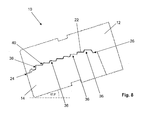
- successive mold halves 12, 14 form - as in Fig. 8 illustrated - the steps 16 of a mold half 12 with the steps 16 of the second mold half 14th a staircase-shaped gap 22 having an inlet 24 and an outlet 26, through which when displaced the mold from the same displaced air and excess molten material can flow.
- the stepped gap 22 can be sealed on both sides over the length of the device 10.
- the device 10 has a collar 42 on both sides, which allows a corresponding sealing of the gap in the lateral direction, wherein the two mold halves 12, 14 are directly adjacent to each other in the region of the collar 42 provided on both sides.
Abstract
Description
Die Erfindung betrifft eine Vorrichtung nach dem Oberbegriff des Anspruchs 1.The invention relates to a device according to the preamble of claim 1.
Beim Befüllen einer Gießform, beispielsweise im Hochdruck- oder Niederdruckguss, beim Kokillenguss oder einem sonstigen Gussverfahren, muss die in der Gießform befindliche Luft aus der Gießform entfernt werden, um ein sauberes Gussergebnis ohne Lunker und Porositäten zu erzielen. Dies kann entweder aktiv durch Evakuieren der Form vor dem eigentlichen Füllvorgang, passiv durch Verdrängen der Luft beim Einbringen des Gussmaterials oder durch eine Kombination beider Verfahren erfolgen.When filling a mold, for example in high pressure or low pressure casting, chill casting or other casting process, the air in the mold must be removed from the mold to achieve a clean casting result without voids and porosities. This can be done either actively by evacuating the mold before the actual filling process, passively by displacing the air when introducing the casting material or by a combination of both methods.
Aus der
Aufgrund der hohen Strömungsgeschwindigkeit des Gussmaterials in den Ventilkörper tritt im Einströmbereich ein erhöhter Verschleiß des Ventilkörpers auf. Es ist bekannt, den Ventilkörper im Einströmbereich mit verschleißfestem Werkstoff auszubilden, doch sind solche verschleißfesten Werkstoffe relativ teuer.Due to the high flow velocity of the casting material into the valve body, increased wear of the valve body occurs in the inflow region. It is known to form the valve body in the inflow region with wear-resistant material, but such wear-resistant materials are relatively expensive.
Ausgehend von diesem Stand der Technik liegt der Erfindung daher die Aufgabe zugrunde, eine Vorrichtung zur Entlüftung einer Gießform alternativ so auszubilden, dass dem Verschleiß im Einströmbereich kostengünstiger entgegengewirkt werden kann. Außerdem liegt der Erfindung die Aufgabe zugrunde, eine Vorrichtung zur Entlüftung einer Gießform zu optimieren, um so Gussteile, insbesondere Druckgussteile, aus vorzugsweise Aluminium- und Magnesiumlegierungen fertigen zu können, die höchsten Qualitätsansprüchen genügen. Eine weitere Aufgabe der Erfindung besteht darin, eine Vorrichtung zur Entlüftung einer Gießform derart weiterzubilden, dass nicht durch vorzeitiges Zufrieren der Entlüftungskanäle die weitere Entlüftung verhindert wird. Eine weitere Aufgabe der Erfindung besteht darin, eine Vorrichtung zur Entlüftung einer Gießform bereitzustellen, die auch ohne Kühleinrichtung und ohne Auswerfer auskommt, auch einfach zu handhaben ist und vergleichsweise wenig Wartungskosten verursacht.Based on this prior art, the invention is therefore the object of an alternative to form a device for venting a mold so that the wear in the inflow can be counteracted cost-effective. In addition, the invention has the object to optimize a device for venting a mold, so as to be able to manufacture castings, in particular die castings, preferably made of aluminum and magnesium alloys that meet the highest quality standards. Another object of the invention is to further develop a device for venting a casting mold in such a way that further venting is not prevented by premature freezing of the venting channels. Another object of the invention is to provide a device for venting a mold, which also works without a cooling device and without ejector, is also easy to handle and causes relatively little maintenance costs.
Diese Aufgabe wird durch eine Vorrichtung nach dem Oberbegriff des Anspruchs 1 durch die kennzeichnenden Merkmale des Anspruchs 1 gelöst. Vorteilhafte Ausgestaltungen und Weiterbildungen der Erfindung ergeben sich aus den Unteransprüchen.This object is achieved by a device according to the preamble of claim 1 by the characterizing features of claim 1. Advantageous embodiments and further developments of the invention will become apparent from the dependent claims.
Ausgehend von einer Vorrichtung zum Entlüften einer Gießform, insbesondere in Form eines Chill-Vents, mit zwei einander gegenüberliegenden und zueinander form- und funktionskomplementären Formhälften, die in ihren zueinander weisenden Flächen jeweils eine Mehrzahl von zueinander im Wesentlichen parallel und zur Strömungsrichtung im Wesentlichen quer verlaufenden Erhebungen und/oder Vertiefungen aufweisen, dergestalt, dass sich bei aufeinander gesetzten Formhälften zwischen den Formhälften zumindest teilweise ein Spalt mit einem Einlass und einem Auslass ausbildet, der insbesondere waschbrett-, labyrinth- und/oder mäanderförmig ist, und durch den beim Füllen der Gießform aus der Gießform verdrängte Luft und überschüssiges schmelzflüssiges Material strömen kann, zeichnet sich die Erfindung dadurch aus, dass zumindest eine oder vorzugsweise jede Formhälfte durch mehrere, in Längsrichtung der Formhälfte nebeneinander angeordnete und lösbar befestigte, vorzugsweise miteinander verbundene Segmente gebildet ist.Starting from a device for venting a mold, in particular in the form of a chill vents, with two mutually opposite and mutually form and function complementary mold halves, each having a plurality of mutually substantially parallel to each other and substantially transverse to the flow direction in their facing surfaces Have elevations and / or depressions, such that at set mold halves between the mold halves at least partially forms a gap with an inlet and an outlet, which is particularly washboard, labyrinth and / or meandering, and by the filling of the mold From the mold displaced air and excess molten material can flow, the invention is characterized in that at least one or preferably each mold half by several, in the longitudinal direction of the mold half juxtaposed and releasably secured, preferably mi Tied segments is formed.
Durch die Segmentierung ist es möglich, kostengünstigste Materialien einzusetzen und die Segmente bei Bedarf, also wenn ein Segment eine Verschleißgrenze erreicht hat, auszuwechseln. Dies ist sehr kostengünstig, da die Formhälften nicht mehr komplett ausgewechselt werden müssen, sondern die Segmente einzeln ausgetauscht werden. Dabei kann so vorgegangen, dass ein, insbesondere das im Einströmbereich erste verschlissene Segment durch ein neues Segment ersetzt wird. Es kann aber auch vorteilhaft sein, wenn das dem verschlissenen Segment benachbarte, weniger verschlissene Segment an dessen Stelle tritt, und an die Stelle des weniger verschlissenen Segments das diesem zuvor benachbarte noch weniger verschlissene Segment tritt usw., bis letztendlich das neue Segment an die Stelle des am wenigstens verschlissenen Segments tritt.The segmentation makes it possible to use the most cost-effective materials and to replace the segments as needed, ie when a segment has reached a wear limit. This is very cost effective because the mold halves no longer need to be completely replaced, but the segments individually be replaced. In this case, it is possible to replace a segment that has been worn first in the inflow region by a new segment. However, it may also be advantageous if the less worn segment adjacent to the worn segment replaces it and the less worn segment is replaced by the previously less worn segment adjacent thereto, and so on, until eventually the new segment comes into place of the at least worn segment occurs.
Es kann von Vorteil sein, wenn die nebeneinander angeordneten Segmente der Formhälfte jeweils zumindest eine Bohrung zur Aufnahme eines Befestigungsmittels aufweisen. Dadurch lassen sich die Segmente an gewünschter Stelle innerhalb der Gießform fixieren.It may be advantageous if the juxtaposed segments of the mold half each have at least one bore for receiving a fastening means. As a result, the segments can be fixed at the desired location within the mold.
Es kann zweckmäßig sein, wenn je Segment zumindest eine, vorzugsweise zwei voneinander beabstandete und in Längsrichtung durchgängige Bohrungen vorgesehen sind, wobei jede in Längsrichtung durchgängige Bohrung zu einer Bohrung eines daneben angeordneten Segments fluchtet, derart, dass die Segmente mittels eines durch die zueinander fluchtenden Bohrungen geführten Befestigungsmittels untereinander verbindbar, insbesondere verschraubbar sind. Durch das Befestigungsmittel kann die Formhälfte zudem vorteilhaft in der Gießform befestigt sein. Die genannte Befestigungsmöglichkeit stellt insbesondere sicher, dass die einzelnen nebeneinander angeordneten Segmente sehr dicht untereinander bzw. miteinander verbunden sind, so dass sich zwischen diesen keine Spalte ausbilden, in die nachteilig flüssiges Metall strömen könnte.It may be expedient if at least one, preferably two spaced apart and longitudinally continuous bores are provided per segment, each longitudinally continuous bore being aligned with a bore of a segment arranged next thereto, such that the segments are aligned by means of holes aligned with one another guided fastener interconnected, in particular screwed. By the fastening means, the mold half may also be advantageously secured in the mold. The above attachment option ensures in particular that the individual juxtaposed segments are very close to each other or connected to each other, so that no gaps form between them, could flow into the disadvantageous liquid metal.
Es kann vorteilhaft sein, wenn je Segment zumindest eine, vorzugsweise mehrere voneinander beabstandete und in Querrichtung von außen einseitig eingebrachte Bohrungen für Befestigungsmittel vorgesehen sind, wodurch jedes Segment mit einem Basiskörper, insbesondere der Gießform, verbindbar, insbesondere verschraubbar ist, vorzugsweise derart, dass die Segmente in Längsrichtung der Formhälfte lösbar nebeneinander angeordnet sind. Diese Befestigungsmöglichkeit erleichtert die Austauschbarkeit einzelner Segmente.It may be advantageous if at least one, preferably a plurality of spaced apart and transversely introduced from the outside unilaterally holes for fastening means are provided per segment, whereby each segment with a base body, in particular the mold, connectable, in particular screwed, preferably such that the Segments in the longitudinal direction of the mold half are detachably arranged side by side. This mounting option facilitates the interchangeability of individual segments.
Es kann vorteilhaft sein, wenn die Segmente der Formhälfte untereinander lösbar form- und/oder kraftschlüssig verbindbar sind.It may be advantageous if the segments of the mold half are releasably positively and / or non-positively connectable.
Es kann von Vorteil sein, wenn die Segmente einer Formhälfte aus dem gleichen Werkstoff, vorzugsweise aus kostengünstigem Stahl, bestehen.It may be advantageous if the segments of a mold half from the same material, preferably made of inexpensive steel exist.
Es kann von Vorteil sein, wenn zumindest zwei Segmente einer Formhälfte aus unterschiedlichem Werkstoff, vorzugsweise aus Stahl, Kupfer, Wolfram oder einer Molybdänlegierung, bestehen.It may be advantageous if at least two segments of a mold half made of different materials, preferably made of steel, copper, tungsten or a molybdenum alloy exist.
Es kann vorteilhaft sein, wenn zumindest zwei Segmente der Formhälfte formidentisch ausgebildet sind, wodurch weniger unterschiedliche Typen von Segmenten vorrätig gehalten werden müssen und die Herstell- sowie Lagerhaltungskosten reduziert werden können.It may be advantageous if at least two segments of the mold half are formed identical in shape, whereby fewer different types of segments must be kept in stock and the manufacturing and storage costs can be reduced.
Es kann vorteilhaft sein, wenn die zueinander fluchtenden Bohrungen als Kühlmittelleitung, insbesondere für Luft oder Wasser, verwendbar sind.It may be advantageous if the mutually aligned bores as a coolant line, in particular for air or water, can be used.
Die Erfindung bezieht sich sowohl als Weiterbildung als auch eigenständig ebenso auf eine Vorrichtung zum Entlüften einer Gießform, insbesondere in Form eines Chill-Vents, mit zwei einander gegenüberliegenden und zueinander form- und funktionskomplementären Formhälften, die in ihren zueinander weisenden Flächen jeweils eine Mehrzahl von zueinander im Wesentlichen parallel und zur Strömungsrichtung im Wesentlichen quer verlaufenden Stufen aufweisen, dergestalt, dass bei aufeinander gesetzten Formhälften die Stufen einer Formhälfte mit den Stufen der zweiten Formhälfte einen treppenförmigen Spalt mit einem Einlass und einem Auslass ausbilden, durch den beim Füllen der Gießform aus der Form verdrängte Luft und überschüssiges schmelzflüssiges Material strömen kann.The invention relates both as a development and independently as well to a device for venting a mold, in particular in the form of a chill-vents, with two mutually opposite and mutually form and function complementary mold halves, in each of their mutually facing surfaces a plurality of each other have substantially parallel and to the flow direction substantially transversely extending stages, such that with successive mold halves, the steps of a mold half with the steps of the second mold half form a stepped gap with an inlet and an outlet, by the filling of the mold from the mold displaced air and excess molten material can flow.
Durch den erfindungsgemäßen treppenförmigen Spalt und die damit einhergehende strömungsoptimierte Geometrie haben Luft und Schmelze über die Länge der Vorrichtung einen Höhenunterschied zu überwinden, wobei die Luft nur einen geringen Widerstand in der Strömung erfährt, die Schmelze dagegen besonders gut innerhalb des treppenförmigen Spalts gebremst wird.The staircase-shaped gap according to the invention and the associated flow-optimized geometry have air and melt over the length of the device to overcome a height difference, the air only a small Resistance in the flow experiences, the melt, however, is particularly well braked within the staircase gap.
Die einzelnen Stufen des treppenförmigen Spaltes weisen vorzugsweise eine über die Länge der Vorrichtung gleichbleibende Breite auf, wobei die Breite des Einlasses und/oder Auslasses von der Breite des Spaltes verschieden sein kann. Für einige Anwendungsfälle kann es auch sinnvoll sein, wenn sich die Breite einer oder mehrerer Stufen des treppenförmigen Spaltes teilweise über die Länge der Vorrichtung von anderen Stufen des treppenförmigen Spaltes unterscheidet.The individual steps of the step-shaped gap preferably have a constant width over the length of the device, wherein the width of the inlet and / or outlet may be different from the width of the gap. For some applications, it may also be useful if the width of one or more steps of the step-shaped gap differs in part over the length of the device from other stages of the step-shaped gap.
Es hat sich herausgestellt, dass eine Kombination der Werkstoffmaterialien, nämlich Wolfram bzw. eine Wolframlegierung für die in Strömungsrichtung gesehen ersten, vorzugsweise ersten drei Stufen und Kupfer bzw. eine Kupferlegierung für die in Strömungsrichtung darauf folgenden Stufen, ein optimales Ergebnis hinsichtlich der Verschleißanfälligkeit und Wärmeableitbarkeit der Vorrichtung ergibt.It has been found that a combination of the material materials, namely tungsten or a tungsten alloy for the flow direction first, preferably first three stages and copper or a copper alloy for the subsequent stages in the flow direction, an optimal result in terms of susceptibility to wear and heat dissipation the device results.
Im Übrigen ist es allgemein bekannt und bedarf keiner weiteren Ausführung, dass beidseitig über die Länge der Vorrichtung der Spalt abgeschlossen sein muss. Die Vorrichtung kann dafür vorteilhaft einen beidseitigen Bund aufweisen, der eine entsprechende Abdichtung des Spaltes in seitlicher Richtung ermöglicht. Im Bereich des beidseitig vorhandenen Bundes liegen die beiden Formhälften spaltlos direkt aufeinander.Incidentally, it is generally known and requires no further execution that on both sides over the length of the device, the gap must be completed. The device can advantageously have a two-sided collar, which allows a corresponding sealing of the gap in the lateral direction. In the area of the federal government on both sides, the two halves of the mold lie directly against each other without a gap.
Selbstverständlich kann die Vorrichtung auch weitere bauliche Elemente aufweisen, beispielsweise Führungselemente zur Ausrichtung der beiden Formhälften zueinander oder Aufnahmen zur Befestigung und Ausrichtung der Vorrichtung innerhalb der Gießform.Of course, the device may also have other structural elements, for example guide elements for aligning the two mold halves to each other or recordings for attachment and alignment of the device within the mold.
Es kann von Vorteil sein, wenn der treppenförmige Spalt mindestens 6, vorzugsweise mindestens 8 aufeinanderfolgende Stufen aufweist.It may be advantageous if the step-shaped gap has at least 6, preferably at least 8 consecutive stages.
Es kann vorteilhaft sein, wenn der treppenförmige Spalt höchstens 12, vorzugsweise höchstens 8 aufeinanderfolgende Stufen aufweist.It may be advantageous if the stepped gap has at most 12, preferably at most 8 consecutive stages.
Es kann zweckmäßig sein, wenn der treppenförmige Spalt wenigstens einen, vorzugsweise einen einzigen Treppenlauf aufweist. Vorliegend werden unter einem Treppenlauf mehrere aufeinanderfolgende Stufen verstanden, die keine Unterbrechung, beispielsweise in Form eines Treppenabsatzes, aufweisen.It may be expedient if the stepped gap has at least one, preferably a single flight of stairs. In the present case, a flight of stairs means several successive stages which have no interruption, for example in the form of a landing.
Es kann aber auch von Vorteil sein, wenn der treppenförmige Spalt wenigstens einen Treppenabsatz aufweist, also eine Art Plattform, die den Treppenlauf unterbricht und den treppenförmigen Spalt in quasi mehrere kleinere Segmente unterteilt.But it may also be advantageous if the staircase-shaped gap has at least one landing, so a kind of platform that interrupts the flight of stairs and divided the staircase-shaped gap in quasi several smaller segments.
Es kann von Vorteil sein, wenn der treppenförmige Spalt eine Treppensteigung mit einem Steigungswinkel von 10 bis 35°, vorzugsweise von 15 bis 20°, ganz bevorzugt von 16 bis 18° aufweist.It may be advantageous if the staircase-shaped gap has a rise in pitch with a pitch angle of 10 to 35 °, preferably 15 to 20 °, more preferably 16 to 18 °.
Es kann zweckmäßig sein, wenn der treppenförmige Spalt wenigstens eine Setzstufe aufweist, die eine andere Höhe aufweist als eine andere Setzstufe des treppenförmigen Spalts. Die Setzstufe ist quasi in Strömungsrichtung vom Spalteinlass betrachtet der vertikale Teil einer Stufe.It may be expedient if the step-shaped gap has at least one riser which has a different height than another riser of the stepped gap. The riser is seen in the direction of flow from the column inlet, the vertical part of a stage.
Um den Schmelzestrom möglichst stark abzubremsen, ist es vorteilhaft, wenn wenigstens eine in Strömungsrichtung vordere, vorzugsweise die erste Setzstufe des treppenförmigen Spalts eine größere Höhe aufweist als wenigstens eine der in Strömungsrichtung folgenden Setzstufen des treppenförmigen Spalts.In order to decelerate the melt stream as strongly as possible, it is advantageous if at least one front step, preferably the first riser of the step-shaped gap has a greater height than at least one of the risers following the step-shaped gap.
Es kann vorteilhaft sein, wenn die Höhe der in Strömungsrichtung ersten Setzstufe des treppenförmigen Spalts zwischen 5 und 20 mm, vorzugsweise zwischen 5 und 10 mm, ganz bevorzugt zwischen 7 und 9 mm beträgt.It may be advantageous if the height of the first riser of the step-shaped gap in the flow direction is between 5 and 20 mm, preferably between 5 and 10 mm, very preferably between 7 and 9 mm.
Es kann von Vorteil sein, wenn die Höhe der in Strömungsrichtung der ersten Setzstufe des treppenförmigen Spalts folgenden Setzstufen zwischen 1 und 10 mm, vorzugsweise zwischen 2 und 7 mm, ganz bevorzugt zwischen 3 und 6 mm beträgt.It may be advantageous if the height of the risers following in the flow direction of the first riser of the step-shaped gap is between 1 and 10 mm, preferably between 2 and 7 mm, very preferably between 3 and 6 mm.
Es kann von Vorteil sein, wenn die Länge der Trittstufen des treppenförmigen Spalts zwischen 5 und 20 mm, vorzugsweise zwischen 10 und 18 mm, ganz bevorzugt zwischen 12 und 15 mm beträgt. Die Trittstufe ist quasi in Strömungsrichtung vom Spalteinlass betrachtet der horizontale Teil einer Stufe.It may be advantageous if the length of the treads of the stepped gap is between 5 and 20 mm, preferably between 10 and 18 mm, very preferably between 12 and 15 mm. The tread is viewed in the flow direction from the column inlet, the horizontal part of a step.
Es kann zweckmäßig sein, wenn die die Lauflänge des treppenförmigen Spalts, gemessen als Gerade zwischen Vorderkante der in Strömungsrichtung gesehen ersten Stufe und Vorderkante der in Strömungsrichtung gesehen letzten Stufe, zwischen 50 und 300 mm, vorzugsweise 70 und 200 mm, ganz besonders zwischen 90 und 150 mm beträgt.It may be expedient if the run length of the step-shaped gap, measured as a straight line between the front edge of the first stage and the front edge viewed in the flow direction, between 50 and 300 mm, preferably 70 and 200 mm, especially between 90 and 150 mm.
Es kann vorteilhaft sein, wenn die Vorrichtung zumindest mit einer Formhälfte in einem Schieber der Gießform angeordnet ist, derart, dass sich diese Formhälfte beim Ziehen des Schiebers von der gegenüberliegenden Formhälfte trennt.It may be advantageous if the device is arranged at least with a mold half in a slide of the mold, such that this mold half separates when pulling the slide from the opposite mold half.
Es kann zweckmäßig sein, wenn die Vorrichtung mit einer Formhälfte im feststehenden Gießformelement und mit der anderen Formhälfte im beweglichen Gießformelement vorgesehen ist.It may be useful if the device is provided with a mold half in the fixed mold element and with the other mold half in the movable mold element.
Es kann von Vorteil sein, wenn die eine Formhälfte der Vorrichtung im feststehenden Gießformelement versenkt angeordnet ist und wenn die andere Formhälfte der Vorrichtung aus dem beweglichen Gießformelement heraustretend angeordnet ist.It may be advantageous if one mold half of the device is sunk in the fixed mold element and if the other mold half the device is arranged heraustretend from the movable mold element.
Es kann vorteilhaft sein, wenn die Gießform eine Druckgießform ist.It may be advantageous if the casting mold is a diecasting mold.
Es kann von Vorteil sein, wenn der sich zwischen den Stufen einer Formhälfte und den Stufen der zweiten Formhälfte ausbildende treppenförmigen Spalt über die Länge der Vorrichtung ein gleichbleibendes oder ein sich änderndes Spaltmaß aufweist.It may be advantageous if the step-shaped gap forming between the steps of a mold half and the steps of the second mold half has a constant or changing gap dimension over the length of the device.
Weitere Einzelheiten und vorteilhafte Ausgestaltungen der Erfindung ergeben sich aus der nachfolgenden Beschreibung von Ausführungsbeispielen in Verbindung mit der Zeichnung. In dieser zeigen:
- Fig. 1
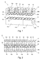
- in schematischer perspektivischer Darstellung eine obere und eine untere Formhälfte einer ersten erfindungsgemäßen Vorrichtung aus jeweils drei Segmenten, wobei die obere Formhälfte transparent dargestellt ist,
- Fig. 2
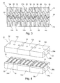
- in schematischer Längsschnittdarstellung zwei aufeinander gesetzte Formhälften einer zweiten erfindungsgemäßen Vorrichtung,
- Fig. 3
- in schematischer Längsschnittdarstellung zwei aufeinander gesetzte Formhälften einer dritten erfindungsgemäßen Vorrichtung,
- Fig. 4
- in schematischer perspektivischer Darstellung eine obere und eine untere Formhälfte der ersten erfindungsgemäßen Vorrichtung,
- Fig. 5
- in schematischer perspektivischer Darstellung ein Segment der unteren Formhälfte der ersten erfindungsgemäßen Vorrichtung,
- Fig. 6
- in schematischer Darstellung eine erste Formhälfte der erfindungsgemäßen Vorrichtung, eingelassen in einem feststehenden Gießformelement,
- Fig. 7
- in schematischer Darstellung eine zweite Formhälfte der erfindungsgemäßen Vorrichtung, herausragend aus einem bewegbaren Gießformelement, insbesondere aus einem separat im bewegbaren Gießformelement vorgesehenen Schieber, und
- Fig. 8
- in schematischer Längsschnittdarstellung zwei aufeinander gesetzte Formhälften der erfindungsgemäßen Vorrichtung.
- Fig. 1
- a schematic perspective view of an upper and a lower mold half of a first device according to the invention from three segments, wherein the upper mold half is shown transparent,
- Fig. 2
- in a schematic longitudinal sectional view of two successive mold halves of a second device according to the invention,
- Fig. 3
- in a schematic longitudinal sectional view of two successive mold halves of a third device according to the invention,
- Fig. 4
- in a schematic perspective view of an upper and a lower mold half of the first device according to the invention,
- Fig. 5
- a schematic perspective view of a segment of the lower mold half of the first device according to the invention,
- Fig. 6
- a schematic representation of a first mold half of the device according to the invention, embedded in a fixed mold element,
- Fig. 7
- a schematic representation of a second mold half of the device according to the invention, outstanding from a movable mold element, in particular from a separately provided in the movable mold element slide, and
- Fig. 8
- in a schematic longitudinal sectional view of two successive mold halves of the device according to the invention.
Werden in den
Wie in den
Zur Befestigung weisen die nebeneinander angeordneten Segmente 12a, 12b, 12c, 14a, 14b, 14c der Formhälfte 12, 14 jeweils zumindest eine Bohrung 28a, 28b, 30 zur Aufnahme eines Befestigungsmittels auf.For attachment, the juxtaposed
Wie in den
Wie insbesondere in
Die Segmente 12a, 12b, 12c, 14a, 14b, 14c der Formhälfte 12, 14 sind untereinander lösbar form- und/oder kraftschlüssig verbindbar.The
Vorteilhaft bestehen die Segmente 12a, 12b, 12c, 14a, 14b, 14c einer Formhälfte 12, 14 aus dem gleichen, möglichst kostengünstigen Werkstoff, vorzugsweise aus Stahl, so dass bei Verschleiß das entsprechende Segment nur ausgewechselt werden muss.Advantageously, the
Es ist natürlich auch möglich, dass zumindest zwei Segmente 12a, 12b, 12c, 14a, 14b, 14c einer Formhälfte 12, 14 aus unterschiedlichem Werkstoff, vorzugsweise aus Stahl, Kupfer, Wolfram oder einer Molybdänlegierung. So kann gegebenenfalls auch auf verschleißfestere Materialien zurückgegriffen werden, wenn dieses angezeigt ist.It is of course also possible that at least two
Besonders sinnvoll ist es, wenn zumindest zwei Segmente 12a, 12b, 12c, 14a, 14b, 14c der Formhälfte 12, 14 formidentisch ausgebildet sind, wodurch eine kostengünstige Austauschbarkeit gegeben ist und hierzu kein große Vielfalt an Segmenten bevorratet werden muss. Das spart auch Herstell- und Lagerhaltungskosten.It is particularly useful if at least two
Es hat sich gezeigt, dass die zueinander fluchtenden Bohrungen 28a, 28b besonders gut als Kühlmittelleitung, insbesondere für Luft oder Wasser, verwendbar sind.It has been shown that the mutually aligned
Die erfindungsgemäße Vorrichtung 10 zum Entlüften einer Gießform kann als Weiterbildung, aber auch eigenständig zwei einander gegenüberliegende und zueinander form- und funktionskomplementäre Formhälften 12, 14 umfassen , die in ihren zueinander weisenden Flächen jeweils eine Mehrzahl von zueinander im Wesentlichen parallel und zur Strömungsrichtung im Wesentlichen quer verlaufenden Stufen 36 aufweisen.The
Die eine Formhälfte 12 der Vorrichtung 10 ist - wie in
Bei aufeinander gesetzten Formhälften 12, 14 bilden - wie in
In successive mold halves 12, 14 form - as in
Der treppenförmige Spalt 22 weist in einem einzigen Treppenlauf acht aufeinanderfolgende Stufen 36 auf.The staircase-shaped
Der treppenförmige Spalt 22 weist in der vorliegenden Ausführungsform eine Treppensteigung mit einem Steigungswinkel von 17,5° auf.The staircase-shaped
Erfindungsgemäß weist die in Strömungsrichtung erste Setzstufe 38 des treppenförmigen Spalts 22 eine größere Höhe auf als die in Strömungsrichtung folgende Setzstufe 40 des treppenförmigen Spalts 22.According to the invention, the
In den
Claims (10)
Applications Claiming Priority (1)
| Application Number | Priority Date | Filing Date | Title |
|---|---|---|---|
| DE102013100442 | 2013-01-16 |
Publications (2)
| Publication Number | Publication Date |
|---|---|
| EP2756896A2 true EP2756896A2 (en) | 2014-07-23 |
| EP2756896A3 EP2756896A3 (en) | 2018-01-10 |
Family
ID=49917573
Family Applications (1)
| Application Number | Title | Priority Date | Filing Date |
|---|---|---|---|
| EP14150199.9A Withdrawn EP2756896A3 (en) | 2013-01-16 | 2014-01-06 | Device for venting a casting mould |
Country Status (4)
| Country | Link |
|---|---|
| US (1) | US9272326B2 (en) |
| EP (1) | EP2756896A3 (en) |
| CN (1) | CN104070150B (en) |
| DE (1) | DE102014100053A1 (en) |
Cited By (1)
| Publication number | Priority date | Publication date | Assignee | Title |
|---|---|---|---|---|
| CZ306937B6 (en) * | 2015-10-05 | 2017-09-27 | Innomia A.S. | A method of producing a venting insert |
Families Citing this family (8)
| Publication number | Priority date | Publication date | Assignee | Title |
|---|---|---|---|---|
| CN106180637B (en) * | 2016-09-30 | 2020-02-14 | 东莞宜安科技股份有限公司 | Die-casting die |
| DE102017123470A1 (en) * | 2017-10-10 | 2019-04-11 | Raskopf GmbH Sauerländer Werkzeugfabrik | Apparatus for producing castings of metal |
| DE102018105570B3 (en) * | 2018-03-12 | 2019-01-31 | InterGuss Gießereiprodukte GmbH | Ventilation device for venting a casting mold |
| CN110397174B (en) * | 2019-08-20 | 2021-08-03 | 马鞍山市金韩防水保温工程有限责任公司 | Waterproof composite insulation board and preparation method thereof |
| KR20210058169A (en) * | 2019-11-13 | 2021-05-24 | 현대자동차주식회사 | Vacuum system for die casting mold |
| DE102019133354B3 (en) * | 2019-12-06 | 2020-11-19 | InterGuss Gießereiprodukte GmbH | Venting device for venting a casting mold with a sawtooth-shaped gap |
| US11213884B1 (en) * | 2020-12-17 | 2022-01-04 | Metal Industries Research And Development Centre | Stationary vacuum valve |
| CN114749629A (en) * | 2022-04-04 | 2022-07-15 | 中国第一汽车股份有限公司 | Tungsten-copper alloy exhaust wave plate |
Citations (2)
| Publication number | Priority date | Publication date | Assignee | Title |
|---|---|---|---|---|
| DE20208464U1 (en) | 2002-05-31 | 2002-11-21 | Mfsa Modell Werkzeug & Formenb | Venting in the foundry process |
| DE202010006751U1 (en) | 2010-05-12 | 2010-08-05 | InterGuss Gießereiprodukte GmbH | mold venting |
Family Cites Families (11)
| Publication number | Priority date | Publication date | Assignee | Title |
|---|---|---|---|---|
| GB855495A (en) * | 1959-06-12 | 1960-11-30 | Walter Milton Goldhamer | Improvements in die casting machines |
| JPS59179309A (en) * | 1983-03-31 | 1984-10-11 | Hitachi Metals Ltd | Gas removing method of molding material and metal die therefor |
| JPH069730Y2 (en) * | 1987-04-10 | 1994-03-16 | トヨタ自動車株式会社 | Cylvent structure in casting mold |
| JP3423873B2 (en) * | 1997-11-20 | 2003-07-07 | 日本碍子株式会社 | Chill vent |
| US6425433B1 (en) * | 2001-02-17 | 2002-07-30 | John W. Hayes | Die casting vacuum apparatus |
| US6513569B1 (en) * | 2001-11-02 | 2003-02-04 | Chun Hsien Li | Vacuum valve for die casting machine |
| US7134637B2 (en) * | 2002-09-27 | 2006-11-14 | Dubay Richard L | Vacuum and vent block for use with molding and casting systems |
| US7770627B2 (en) * | 2003-10-01 | 2010-08-10 | Cast Centre Pty Ltd | Venting assembly for a casting mould |
| US7631851B2 (en) * | 2007-03-02 | 2009-12-15 | Dubay Richard L | High volume vacuum/vent block for molding and casting systems |
| CN201684910U (en) * | 2010-05-31 | 2010-12-29 | 广东鸿特精密技术股份有限公司 | Improved structure of exhaust block |
| US8424587B1 (en) * | 2012-06-05 | 2013-04-23 | Richard L. Dubay | Vacuum/vent block having non-uniform purge passage |
-
2014
- 2014-01-02 US US14/146,147 patent/US9272326B2/en active Active
- 2014-01-06 DE DE102014100053.6A patent/DE102014100053A1/en not_active Withdrawn
- 2014-01-06 EP EP14150199.9A patent/EP2756896A3/en not_active Withdrawn
- 2014-01-16 CN CN201410021544.6A patent/CN104070150B/en not_active Expired - Fee Related
Patent Citations (2)
| Publication number | Priority date | Publication date | Assignee | Title |
|---|---|---|---|---|
| DE20208464U1 (en) | 2002-05-31 | 2002-11-21 | Mfsa Modell Werkzeug & Formenb | Venting in the foundry process |
| DE202010006751U1 (en) | 2010-05-12 | 2010-08-05 | InterGuss Gießereiprodukte GmbH | mold venting |
Cited By (1)
| Publication number | Priority date | Publication date | Assignee | Title |
|---|---|---|---|---|
| CZ306937B6 (en) * | 2015-10-05 | 2017-09-27 | Innomia A.S. | A method of producing a venting insert |
Also Published As
| Publication number | Publication date |
|---|---|
| CN104070150A (en) | 2014-10-01 |
| DE102014100053A1 (en) | 2014-07-17 |
| EP2756896A3 (en) | 2018-01-10 |
| US20140196864A1 (en) | 2014-07-17 |
| US9272326B2 (en) | 2016-03-01 |
| CN104070150B (en) | 2018-09-21 |
Similar Documents
| Publication | Publication Date | Title |
|---|---|---|
| EP2756896A2 (en) | Device for venting a casting mould | |
| DE102016124801B3 (en) | Mold plate and mold | |
| DE10058428B4 (en) | Cylinder liner and cylinder block and method for producing the same | |
| EP2321075B1 (en) | Strand casting mold for liquid metal, particularly for liquid steel | |
| DE102012004057B3 (en) | Device for venting a casting mold | |
| DE102011083268B4 (en) | Mold insert assembly and method of casting | |
| DE112012001298T5 (en) | Tire vulcanizing mold and method for its production | |
| EP3523069B1 (en) | Mold divider for installing in a mold | |
| WO2016193458A1 (en) | Hot runner feed system for a diecasting mould | |
| EP2049286A1 (en) | Extrusion die for liquid metals, in particular for liquid steel materials | |
| EP3108983B1 (en) | Pouring assembly | |
| WO2013004214A1 (en) | Method for producing a piston for an internal combustion engine | |
| EP3320788B1 (en) | Machine for producing rod-shaped products for the tobacco processing industry and related forming set | |
| DE102015215328A1 (en) | A method of continuously casting a metal strand and determining the shrinkage of a continuously cast metal strand | |
| DE19829606A1 (en) | Broad side of a slab mold | |
| EP0968778A1 (en) | Device and method for continuous casting of hollow profiles | |
| DE202005001310U1 (en) | Verbundgußplatte | |
| DE102014104025A1 (en) | Method and device for the production of an internal thread having metallic castings and such castings | |
| EP2548675A1 (en) | Mould for strand casting metallic long products | |
| DE202013103821U1 (en) | Mandrel element for an aluminum extrusion device | |
| EP3525955B1 (en) | Mold having a mold divider | |
| AT522037B1 (en) | Mold unit for the continuous casting of metal products as well as a continuous caster | |
| EP1393837B1 (en) | Mould pipe | |
| WO2021163740A1 (en) | Method for producing a metal component, and apparatus therefor | |
| DE102017211108A1 (en) | Mold plate and mold for a continuous casting plant and continuous casting process |
Legal Events
| Date | Code | Title | Description |
|---|---|---|---|
| PUAI | Public reference made under article 153(3) epc to a published international application that has entered the european phase |
Free format text: ORIGINAL CODE: 0009012 |
|
| 17P | Request for examination filed |
Effective date: 20140106 |
|
| AK | Designated contracting states |
Kind code of ref document: A2 Designated state(s): AL AT BE BG CH CY CZ DE DK EE ES FI FR GB GR HR HU IE IS IT LI LT LU LV MC MK MT NL NO PL PT RO RS SE SI SK SM TR |
|
| AX | Request for extension of the european patent |
Extension state: BA ME |
|
| PUAL | Search report despatched |
Free format text: ORIGINAL CODE: 0009013 |
|
| AK | Designated contracting states |
Kind code of ref document: A3 Designated state(s): AL AT BE BG CH CY CZ DE DK EE ES FI FR GB GR HR HU IE IS IT LI LT LU LV MC MK MT NL NO PL PT RO RS SE SI SK SM TR |
|
| AX | Request for extension of the european patent |
Extension state: BA ME |
|
| RIC1 | Information provided on ipc code assigned before grant |
Ipc: B22C 9/06 20060101AFI20171206BHEP |
|
| STAA | Information on the status of an ep patent application or granted ep patent |
Free format text: STATUS: REQUEST FOR EXAMINATION WAS MADE |
|
| R17P | Request for examination filed (corrected) |
Effective date: 20180620 |
|
| RBV | Designated contracting states (corrected) |
Designated state(s): AL AT BE BG CH CY CZ DE DK EE ES FI FR GB GR HR HU IE IS IT LI LT LU LV MC MK MT NL NO PL PT RO RS SE SI SK SM TR |
|
| STAA | Information on the status of an ep patent application or granted ep patent |
Free format text: STATUS: EXAMINATION IS IN PROGRESS |
|
| 17Q | First examination report despatched |
Effective date: 20190415 |
|
| GRAP | Despatch of communication of intention to grant a patent |
Free format text: ORIGINAL CODE: EPIDOSNIGR1 |
|
| STAA | Information on the status of an ep patent application or granted ep patent |
Free format text: STATUS: GRANT OF PATENT IS INTENDED |
|
| INTG | Intention to grant announced |
Effective date: 20201126 |
|
| STAA | Information on the status of an ep patent application or granted ep patent |
Free format text: STATUS: THE APPLICATION IS DEEMED TO BE WITHDRAWN |
|
| 18D | Application deemed to be withdrawn |
Effective date: 20210407 |