EP2756210B1 - Verfahren zum ansteuern eines antriebs-stranges eines fahrzeugs und vorrichtung zur durchführung des verfahrens - Google Patents
Verfahren zum ansteuern eines antriebs-stranges eines fahrzeugs und vorrichtung zur durchführung des verfahrens Download PDFInfo
- Publication number
- EP2756210B1 EP2756210B1 EP12762533.3A EP12762533A EP2756210B1 EP 2756210 B1 EP2756210 B1 EP 2756210B1 EP 12762533 A EP12762533 A EP 12762533A EP 2756210 B1 EP2756210 B1 EP 2756210B1
- Authority
- EP
- European Patent Office
- Prior art keywords
- control
- travel
- speed
- internal combustion
- combustion engine
- Prior art date
- Legal status (The legal status is an assumption and is not a legal conclusion. Google has not performed a legal analysis and makes no representation as to the accuracy of the status listed.)
- Active
Links
Images
Classifications
-
- F—MECHANICAL ENGINEERING; LIGHTING; HEATING; WEAPONS; BLASTING
- F02—COMBUSTION ENGINES; HOT-GAS OR COMBUSTION-PRODUCT ENGINE PLANTS
- F02D—CONTROLLING COMBUSTION ENGINES
- F02D28/00—Program control of engines
-
- B—PERFORMING OPERATIONS; TRANSPORTING
- B60—VEHICLES IN GENERAL
- B60W—CONJOINT CONTROL OF VEHICLE SUB-UNITS OF DIFFERENT TYPE OR DIFFERENT FUNCTION; CONTROL SYSTEMS SPECIALLY ADAPTED FOR HYBRID VEHICLES; ROAD VEHICLE DRIVE CONTROL SYSTEMS FOR PURPOSES NOT RELATED TO THE CONTROL OF A PARTICULAR SUB-UNIT
- B60W10/00—Conjoint control of vehicle sub-units of different type or different function
- B60W10/04—Conjoint control of vehicle sub-units of different type or different function including control of propulsion units
- B60W10/06—Conjoint control of vehicle sub-units of different type or different function including control of propulsion units including control of combustion engines
-
- B—PERFORMING OPERATIONS; TRANSPORTING
- B60—VEHICLES IN GENERAL
- B60W—CONJOINT CONTROL OF VEHICLE SUB-UNITS OF DIFFERENT TYPE OR DIFFERENT FUNCTION; CONTROL SYSTEMS SPECIALLY ADAPTED FOR HYBRID VEHICLES; ROAD VEHICLE DRIVE CONTROL SYSTEMS FOR PURPOSES NOT RELATED TO THE CONTROL OF A PARTICULAR SUB-UNIT
- B60W30/00—Purposes of road vehicle drive control systems not related to the control of a particular sub-unit, e.g. of systems using conjoint control of vehicle sub-units
- B60W30/18—Propelling the vehicle
- B60W30/18009—Propelling the vehicle related to particular drive situations
- B60W30/18036—Reversing
- B60W30/18045—Rocking, i.e. fast change between forward and reverse
-
- F—MECHANICAL ENGINEERING; LIGHTING; HEATING; WEAPONS; BLASTING
- F16—ENGINEERING ELEMENTS AND UNITS; GENERAL MEASURES FOR PRODUCING AND MAINTAINING EFFECTIVE FUNCTIONING OF MACHINES OR INSTALLATIONS; THERMAL INSULATION IN GENERAL
- F16H—GEARING
- F16H61/00—Control functions within control units of change-speed- or reversing-gearings for conveying rotary motion ; Control of exclusively fluid gearing, friction gearing, gearings with endless flexible members or other particular types of gearing
- F16H61/38—Control of exclusively fluid gearing
- F16H61/40—Control of exclusively fluid gearing hydrostatic
- F16H61/42—Control of exclusively fluid gearing hydrostatic involving adjustment of a pump or motor with adjustable output or capacity
- F16H61/431—Pump capacity control by electro-hydraulic control means, e.g. using solenoid valves
-
- F—MECHANICAL ENGINEERING; LIGHTING; HEATING; WEAPONS; BLASTING
- F16—ENGINEERING ELEMENTS AND UNITS; GENERAL MEASURES FOR PRODUCING AND MAINTAINING EFFECTIVE FUNCTIONING OF MACHINES OR INSTALLATIONS; THERMAL INSULATION IN GENERAL
- F16H—GEARING
- F16H61/00—Control functions within control units of change-speed- or reversing-gearings for conveying rotary motion ; Control of exclusively fluid gearing, friction gearing, gearings with endless flexible members or other particular types of gearing
- F16H61/38—Control of exclusively fluid gearing
- F16H61/40—Control of exclusively fluid gearing hydrostatic
- F16H61/46—Automatic regulation in accordance with output requirements
- F16H61/465—Automatic regulation in accordance with output requirements for achieving a target input speed
-
- B—PERFORMING OPERATIONS; TRANSPORTING
- B60—VEHICLES IN GENERAL
- B60W—CONJOINT CONTROL OF VEHICLE SUB-UNITS OF DIFFERENT TYPE OR DIFFERENT FUNCTION; CONTROL SYSTEMS SPECIALLY ADAPTED FOR HYBRID VEHICLES; ROAD VEHICLE DRIVE CONTROL SYSTEMS FOR PURPOSES NOT RELATED TO THE CONTROL OF A PARTICULAR SUB-UNIT
- B60W2540/00—Input parameters relating to occupants
- B60W2540/10—Accelerator pedal position
- B60W2540/106—Rate of change
-
- B—PERFORMING OPERATIONS; TRANSPORTING
- B60—VEHICLES IN GENERAL
- B60W—CONJOINT CONTROL OF VEHICLE SUB-UNITS OF DIFFERENT TYPE OR DIFFERENT FUNCTION; CONTROL SYSTEMS SPECIALLY ADAPTED FOR HYBRID VEHICLES; ROAD VEHICLE DRIVE CONTROL SYSTEMS FOR PURPOSES NOT RELATED TO THE CONTROL OF A PARTICULAR SUB-UNIT
- B60W2540/00—Input parameters relating to occupants
- B60W2540/16—Ratio selector position
-
- B—PERFORMING OPERATIONS; TRANSPORTING
- B60—VEHICLES IN GENERAL
- B60W—CONJOINT CONTROL OF VEHICLE SUB-UNITS OF DIFFERENT TYPE OR DIFFERENT FUNCTION; CONTROL SYSTEMS SPECIALLY ADAPTED FOR HYBRID VEHICLES; ROAD VEHICLE DRIVE CONTROL SYSTEMS FOR PURPOSES NOT RELATED TO THE CONTROL OF A PARTICULAR SUB-UNIT
- B60W2710/00—Output or target parameters relating to a particular sub-units
- B60W2710/06—Combustion engines, Gas turbines
- B60W2710/0644—Engine speed
-
- B—PERFORMING OPERATIONS; TRANSPORTING
- B60—VEHICLES IN GENERAL
- B60Y—INDEXING SCHEME RELATING TO ASPECTS CROSS-CUTTING VEHICLE TECHNOLOGY
- B60Y2200/00—Type of vehicle
- B60Y2200/40—Special vehicles
- B60Y2200/41—Construction vehicles, e.g. graders, excavators
- B60Y2200/413—Compactors
Definitions
- the invention relates to a method for controlling a drive train of a vehicle, in particular the drive train of a compaction machine in earthworks, wherein a control of the drive pump is independent of the rotational speed of the internal combustion engine according to a predetermined control profile, if a predetermined driving operation is present.
- the invention further relates to an apparatus for carrying out the method and to a use of this method in a soil compaction machine, in particular a landfill compactor, and a soil compaction machine with such a device.
- an operator controls the power of the drive train on the speed of an internal combustion engine.
- a feed pump is coupled to the output shaft of the internal combustion engine, which generates a control pressure proportional to the rotational speed of the internal combustion engine.
- the control pressure acts on a pressure-dependent drive pump, which acts on the drive motor.
- the delivery rate of the driving pump is proportional to this control pressure, so that the driving speed is also proportional to the engine speed of the internal combustion engine.
- the driving speed is thus firmly tied to the engine speed of the internal combustion engine.
- the invention is therefore based on the object to provide a method and an apparatus of the type mentioned, which reduces engine wear and fuel consumption.
- the controller is determined by the timing of the operation of a driver that the control profile is set so that frequent speed and / or load changes of the engine are avoided, the speed of the internal combustion engine within a first predetermined Fixed time interval is fixed, that the control profile is set so that the speed of the internal combustion engine within a second predetermined time interval T2 follows a predetermined course, and that the predetermined intervals are set so that the succession of accelerations and braking within a typical interval no speed change he follows.
- the object is achieved in that on the input side to a drive motor acting on the drive pump, a pressure control valve is present, which is controlled by a machine control, wherein in the machine control the driving profile is stored.
- a pressure control valve is present, which is controlled by a machine control, wherein in the machine control the driving profile is stored.
- the invention can be used in all vehicles that are operated with a frequent change of direction or frequently changing driving speeds.
- a preferred use of the method and apparatus is a self-propelled compacting machine or a landfill compactor.
- the control profile is determined statically or dynamically depending on the position of the direction switch and the time course of the accelerator pedal.
- the invention makes use of the basic idea of operating the internal combustion engine in an optimal operating range under certain conditions of use or during a specific driving operation, so that the internal combustion engine is not exposed to repeated speed changes, in particular not over a large rotational speed range. While in conventional controls stop and restart or reversing the direction of the machine concerned is only possible if the speed of the engine is lowered to idle speed, to then be raised again to the rated speed, according to the invention the speed of the engine in the optimal working range, even if the traction motor is stopped or switched in the direction of travel becomes. Even in the partial load range, the engine speed is lowered.
- the invention thus has the advantage that the number of speed and load changes of the internal combustion engine are reduced, resulting in lower fuel consumption and longer service life of the internal combustion engine.
- the comfort of the operator increases, since the otherwise usual driving through the speed range is perceived as subjectively unpleasant.
- the machine in question can be stopped at a predetermined speed of the engine above the idle speed, for example, at the rated speed of the engine.
- a preferred embodiment of the invention is that the speed of the internal combustion engine is fixedly determined within a first predetermined time interval and, alternatively or additionally, follows a predetermined course within a second predetermined time interval. This makes it possible, on the one hand to maintain the speed for briefly occurring stops or changes in direction and, on the other hand, to adjust the engine speed for slightly longer pauses between two changes in the driving behavior without major fluctuations in speed occurring.
- the course of the speed change within the second predetermined time interval can preferably be carried out with a predetermined time delay and / or a predetermined attenuation of that course which would occur if no control according to the invention were present.
- a particularly agile acceleration of the vehicle concerned is achieved in that the control profile is set so that the speed of the internal combustion engine is set to a predetermined value in standby mode (standby speed).
- the machine can be approached in this way compared to conventional machines with increased engine speed.
- Favorable is a speed which corresponds to about 80% of the rated speed of the internal combustion engine.
- control profile is created from driving patterns of a typical driving operation.
- driving patterns of a typical driving operation it is known from the working sequences of a machine that certain cycles are repeated, for example, that a machine repeatedly travels backwards and forwards in succession. This is typical for a refuse compactor, for example. Since you also the temporal Knowing the course of these forward / reverse drives, you can set the control profile so that speed fluctuations are avoided.
- control profile is adjusted during operation of the machine.
- a flexible adaptation to the current operating conditions can take place, for example, the duration of successive forward / reverse drives, changing loads or the topography in which the vehicle in question moves, such as gradients, curves or the like.
- the control can be effected in a simple manner by generating a control pressure which determines the delivery rate as a function of the predetermined control profile.
- the inventive solution of the task by means of a pressure control valve has the advantage that the "hydraulic load limit control" of the drive pump is maintained. So there is no electronic load limit control required.
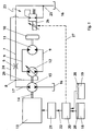
- a vehicle wheel 10 of a soil compaction machine is driven by a drive train that includes a hydraulic traction motor 11, a pressure-dependent traction pump 12, a feed pump 15 and an internal combustion engine 13.
- the drive pump 12 leads the traction motor 11 via lines 9 hydraulic fluid.
- the applied in the control line 29 control pressure is hereinafter referred to as effective control pressure.
- the internal combustion engine 13 drives the drive pump 12 and the feed pump 15 via an output shaft 14. This promotes a main flow of hydraulic fluid from a tank 16 in a main line 17, which branches at a node 8 in the control line 29 to the drive pump 12 and a return line 7 to the tank 16.
- the feed pump 15 generates a control pressure in the main line 17, which is proportional to the rotational speed of the internal combustion engine 13, which is referred to below as a speed-dependent control pressure.
- At node 8 is also a pressure regulating line 24 with a pressure control valve 23 which is controlled by an electronic machine control 20.
- the pressure applied in the pressure regulating line 24 is hereinafter referred to as the regulating pressure.
- the effective control pressure in the control line 29 is thus determined by the speed-dependent control pressure in the main line 17 and the Regulier horr in the pressure regulating line 24, which is superimposed on the speed-dependent control pressure.
- the effective control pressure in the control line 29 is regulated by the fact that the speed-dependent control pressure can be reduced by the pressure control valve 23.
- the pressure regulating line 24 is connected via a further node 25 downstream of the valve 6 to the return line 7 and the tank 16. Pressure equalization between the effective control pressure at the input of the drive pump 12 and the pressure in the return line 7, which corresponds to the tank pressure, can thus take place via the pressure control valve 23.
- the speed-dependent pressure built up by the feed pump 15 at the node 8 decreases accordingly, so that only the differential pressure in the control line 29 is applied, even if the pumping power of the feed pump 15, i. the main volume flow is not reduced.
- the voltage applied to the pressure-dependent drive pump 12 effective control pressure is thus determined by the speed-dependent control pressure of the feed pump 15 and in an independent overlay and the pressure control valve 23.
- the speed-dependent control pressure in the main line 17 is completely discharged via the pressure regulating valve 23, the effective pressure in the control line 29 is reduced to "zero" and the vehicle stops. If the effective pressure in the control line 29 is increased again by appropriate actuation of the pressure control valve 23, the soil compacting machine sets in motion again in accordance with the differential pressure at the node 8.
- the driving speed can therefore be determined without changing the rotational speed of the internal combustion engine 13.
- the pressure control valve 23 is executed in the illustrated embodiment with a magnetic control coil 26 with armature and provided with a return spring.
- the control of the pressure control valve 23 via a control signal from the machine control 20, which is connected via a control line 27 directly to the input of the control coil 26 of the pressure control valve 23.
- the driving speed and the desired direction of travel of the soil compaction machine are entered by an operator.
- the driver may also be configured as a joystick, slider, wheel or the like, with which an operator controls the acceleration and deceleration of the vehicle.
- the positions of the accelerator pedal 18 and the direction switch 19 are monitored by sensors 28.
- the respective output signals are supplied to the electronic machine controller 20, which is connected upstream of an electronic engine controller 21 and connected to it, for example via a CAN bus 22.
- the engine controller 20 controls, via the engine controller 21, the rotational speed of the engine 13 and, via the pressure regulating valve 23, the vehicle speed as described above.
- the engine control unit 20 evaluates the position of the accelerator pedal 18 and the direction switch 19 and generates a target value for the rotational speed of the internal combustion engine 13, which is given to the motor controller 21, and generates the control signal for the control coil 26 of the pressure control valve 23, in each case depending on a statically or dynamically determined control profile.
- a statically determined control profile is determined by tests and then stored in the machine control. During operation, the machine control accesses this predetermined profile.
- a dynamic determination is made by the fact that during the operation of the soil compacting machine frequently repeated driving and acceleration processes and / / or determined driving cycles and from which the control profile for the current use is derived.
- the control profile is based on the evaluation of typical trajectories of the soil compaction machine, which are represented by the course of the position changes of the accelerator pedal. It causes that in the presence of a typical course of the changes in position of the accelerator pedal, the traction motor is driven in accordance with the positions of the accelerator pedal, but that the rotational speed of the internal combustion engine 13 does not necessarily follow the position of the accelerator pedal 18. Rather, the speed is specified by the control profile.
- Typical trajectories are short acceleration and braking and change between forward and reverse in frequent change.
- Predetermined changes in position of the accelerator pedal 18 within a first predetermined time interval do not lead to a change in the rated speed. Further predetermined position changes within a second predetermined time interval lead to the standby speed or the idle speed.
- the control profile selects the predetermined time intervals based on typical acceleration and braking operations as well as forward and reverse travel during a work operation of the soil compaction machine.
- the intervals are set so that no speed change occurs or speed changes are delayed in the succession of accelerations and braking within a typical interval, preferably in predetermined levels.
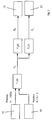
- Fig. 2 the control is based on the following functions. It is constantly the current position of the accelerator pedal 18 is determined, ie, it is determined whether the accelerator pedal 18 is operated at all and to what extent the accelerator pedal 18 is optionally actuated. This results in values that can be described from a minimum of 0% to a maximum of 100%. In conjunction with a value which is derived from the position of the direction-of-travel switch 19, a speed setpoint value V S is determined in a first function f 1 (x).
- the speed set point V S is subject to a second and third function f 2 (x), f 3 (x) respectively.
- a speed signal D S for driving the internal combustion engine 13 is derived therefrom.
- it depends on the speed setpoint V S and the speed of the diesel engine (ie, the internal combustion engine) generates a target value P S for driving the pressure control valve 23.
- the control also includes the filter function of a low-pass filter, according to which only actuations of the accelerator pedal 18 take effect, which does not take place within predetermined time periods.
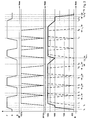
- the control profile is exemplified by the diagrams of Fig. 3 explained in which the course of the accelerator pedal position FP by means of its deflection in%, the position of the direction switch SF in forward, backward and neutral position and the speed D of the internal combustion engine in revolutions per minute (n / rpm) over the time in seconds ( t / s) are shown.
- the position SF of the direction switch over the time course FP of the accelerator pedal position illustrate a typical driving course of the soil compaction machine with frequent reversing.
- the direction switch of the soil compaction machine is first switched from the neutral position N and at idle speed of the engine (here 800 rpm) to the forward drive position F at time t0.
- the speed D is then controlled by the machine controller 20 (FIG. Fig. 1 ) is increased until it reaches a standby speed (here 1600 rpm) at time t1, without the accelerator pedal having to be pressed.
- the accelerator pedal is then pressed at time t2 and brought from position 0% in the position 100%, the speed of the engine increases and the vehicle is accelerated forward until it at time t3 its rated speed (here 1900 rpm) and its final speed has reached.
- the accelerator pedal remains depressed in its maximum position and the vehicle advances at a constant speed until the accelerator pedal is returned to the 0% position at the time t4 and the vehicle is braked.
- the direction switch is then set to reverse R.
- the vehicle is then reversed by pressing the accelerator pedal accelerates until it reverses at constant speed at time t6.
- it is braked again at time t7 by withdrawing the accelerator pedal to 0%, and at time t8, the direction switch is again set to forward travel F.
- the forward and reverse drive is now repeated according to the same temporal pattern, which is typical for example for the labor input of a refuse compactor.
- the time interval between the initiation of the braking, that is, when the accelerator pedal leaves the 100% position until the time when the subsequent acceleration is completed, ie, when the accelerator pedal is in the 100% position, is typically about 2 to 3 sec.
- the repeated starting and braking according to dot-dash line would lead to a four-time speed increase up to a rated speed of here 1900 rpm and four speed drops to idle speed.
- the first speed increase would be from the idle speed at time t2 when the accelerator pedal is depressed.
- the control profile for the rotational speed of the internal combustion engine from the driving course described is created as follows for this period.
- the speed is already raised when operating the direction switch at time t1 to a standby speed, which it reaches before the time t2, and preferably corresponds to about 80% of the rated speed, here 1600 rpm.
- the rated speed is reached faster at the time t3 than in a conventional control.
- the rated speed is maintained constant for a presettable first time interval T1.
- the speed within a second time interval T2 is slowly reduced until they either the standby speed achieved, which is the case in the example at time t12, or the accelerator pedal is pressed again at the time t13. If the accelerator pedal is actuated to accelerate, as in the example shown at the time t12, the rated speed is reset. The standby speed is not exceeded during the entire driving operation, ie as long as the direction switch is set to forward or reverse.
- the direction switch is set to neutral N, i. the driving is stopped. Thereupon, within a presettable third time interval T3, in this case 2 sec, a slow reduction to the idling speed, which is reached at the time t19, takes place at the time t18. Only if the direction switch is operated again in the meantime, the standby speed is resumed.
- the switching of the speed thus takes place in a predetermined sequence between three stages, namely the idle speed, the standby speed and the rated speed.
- the engine speed is set by the engine controller without using the control profile.
- the use of the control profile can optionally be switched off, for example for maintenance and repair work.
Landscapes
- Engineering & Computer Science (AREA)
- Mechanical Engineering (AREA)
- General Engineering & Computer Science (AREA)
- Chemical & Material Sciences (AREA)
- Combustion & Propulsion (AREA)
- Transportation (AREA)
- Automation & Control Theory (AREA)
- Control Of Vehicle Engines Or Engines For Specific Uses (AREA)
- Operation Control Of Excavators (AREA)
Description
- Die Erfindung betrifft ein Verfahren zum Ansteuern eines Antriebsstranges eines Fahrzeugs, insbesondere dem Antriebsstrang einer Verdichtungsmaschine im Erdbau, wobei eine Steuerung der Fahrpumpe unabhängig von der Drehzahl des Verbrennungsmotors nach einem vorgegebenen Steuerungsprofil erfolgt, wenn ein vorgegebener Fahrbetrieb vorliegt. Die Erfindung betrifft ferner eine Vorrichtung zur Durchführung des Verfahrens sowie eine Verwendung dieses Verfahrens bei einer Bodenverdichtungsmaschine, insbesondere einem Müllverdichter, und eine Bodenverdichtungsmaschine mit einer derartigen Vorrichtung.
- Bei bekannten Verdichtungsmaschinen im Erdbau mit einem hydraulischen Fahrmotor steuert eine Bedienungsperson die Leistung des Antriebsstranges über die Drehzahl eines Verbrennungsmotors. Dazu ist eine Speisepumpe mit der Abtriebswelle des Verbrennungsmotors gekoppelt, welche einen Steuerdruck proportional zur Drehzahl des Verbrennungsmotors erzeugt. Der Steuerdruck wirkt auf eine druckabhängige Fahrpumpe, welche den Fahrmotor beaufschlagt. Die Fördermenge der Fahrpumpe ist proportional zu diesem Steuerdruck, so dass die Fahrgeschwindigkeit ebenfalls proportional zur Motordrehzahl des Verbrennungsmotors ist. Die Fahrgeschwindigkeit ist somit fest an die Motordrehzahl des Verbrennungsmotors gebunden.
- Es ist auch ein Verfahren zur Leistungsregelung von Verdichtungsmaschinen im Erdbau und eine entsprechende Vorrichtung aus
EP 1722036 A2 bekannt. Dabei erfolgt eine hydraulische Leistungsregelung des Fahrmotors dadurch, dass in die Hydraulikhauptleitung zwischen dem Fahrmotor und einer ihn versorgenden Speisepumpe ein verstellbares Stromregelventil geschaltet ist. Mit diesem wird der dem Fahrmotor zugeführte Volumenstrom mengenmäßig proportional zu einer Steuergröße verändert, welche aus einer Messung der Bodensteifigkeit des zu verdichtenden Untergrunds abgeleitet ist. - Aus
DE 4425130 A1 undDE 112008002977 T5 sind Verfahren zur Steuerung des Fahrantriebs unabhängig von der Drehzahl des Verbrennungsmotors bekannt. Aus der gattungsgemäßenUS 2009/264252 A1 ,EP 1 544 440 A1 undUS 5 277 269 A sind Verfahren bekannt, in denen die Drehzahl des Verbrennungsmotors zum Erreichen einer optimalen Funktion des Hydraulikantriebs reguliert wird. - In der Praxis muss bei bestimmten Einsatzbedingungen häufig die Fahrtrichtung oder die Beschleunigung des betreffenden Fahrzeugs verändert werden, was mit ungünstigem Kraftstoffverbrauch und hohen Verschleiß des Verbrennungsmotors verbunden ist.
- Der Erfindung liegt daher die Aufgabe zu Grunde, ein Verfahren und eine Vorrichtung der eingangs genannten Art anzugeben, welche den Motorverschleiß und den Kraftstoffverbrauch verringert.
- Diese Aufgabe wird verfahrensmäßig dadurch gelöst, dass die Steuerung vom zeitlichen Verlauf der Betätigung eines Fahrgebers bestimmt wird, dass das Steuerungsprofil so eingestellt ist, dass häufige Drehzahl-/ und/ oder Lastwechsel des Verbrennungsmotors vermieden werden, wobei die Drehzahl des Verbrennungsmotors innerhalb eines ersten vorgegebenen Zeitintervalls fest vorgegeben ist, dass das Steuerungsprofil so eingestellt ist, dass die Drehzahl des Verbrennungsmotors innerhalb eines zweiten vorgegebenen Zeitintervalls T2 einem vorgegebenen Verlauf folgt, und dass die vorgegebenen Intervalle so festgesetzt sind, dass beim Aufeinanderfolgen von Beschleunigen und Bremsen innerhalb eines typischen Intervalls keine Drehzahländerung erfolgt.
- Vorrichtungsmäßig wird die Aufgabe dadurch gelöst, dass eingangsseitig zu einer den Fahrmotor beaufschlagenden Fahrpumpe ein Druckregelventil vorhanden ist, welches von einer Maschinensteuerung angesteuert ist, wobei in der Maschinensteuerung das Fahrprofil abgespeichert ist. Grundsätzlich kann die Erfindung bei allen Fahrzeugen eingesetzt werden, die mit einem häufigen Fahrtrichtungswechsel oder häufig wechselnden Fahrgeschwindigkeiten betrieben werden. Eine bevorzugte Verwendung des Verfahrens und der Vorrichtung ist eine selbstfahrende Verdichtungsmaschine oder ein Müllverdichter. Vorteilhafte Weiterbildungen der Erfindung sind in den abhängigen Ansprüchen beschrieben.
- Das Steuerungsprofil wird statisch oder dynamisch abhängig von der Stellung des Fahrtrichtungsschalters und dem zeitlichen Verlauf des Fahrpedals ermittelt. Die Erfindung macht sich die Grundidee zunutze, den Verbrennungsmotor bei bestimmten Einsatzbedingungen bzw. bei einem bestimmten Fahrbetrieb in einem optimalen Arbeitsbereich zu betreiben, so dass der Verbrennungsmotor nicht einem wiederholten Drehzahlwechsel ausgesetzt ist, insbesondere nicht über einen großen Drehzahlbereich. Während bei herkömmlichen Steuerungen ein Anhalten und Wiederanfahren oder eine Fahrtrichtungsumkehr der betreffenden Maschine nur möglich ist, wenn die Drehzahl des Verbrennungsmotors auf Leerlaufdrehzahl abgesenkt wird, um danach wieder auf die Nenndrehzahl angehoben zu werden, bleibt erfindungsgemäß die Drehzahl des Verbrennungsmotors im optimalen Arbeitsbereich, auch wenn der Fahrmotor gestoppt oder in der Fahrtrichtung umgeschaltet wird. Auch im Teillastbereich erfolgt eine Absenkung der Motordrehzahl.
- Die Erfindung hat somit den Vorteil, dass die Anzahl der Drehzahl-/ und Lastwechsel des Verbrennungsmotors verringert werden, was zu geringerem Kraftstoffverbrauch und höheren Standzeiten des Verbrennungsmotors führt. Außerdem erhöht sich der Komfort der Bedienperson, da das ansonsten übliche Durchfahren des Drehzahlbereichs als subjektiv unangenehm empfunden wird. Auch kann die betreffende Maschine bei einer vorgebbaren Drehzahl des Verbrennungsmotors oberhalb der Leerlaufdrehzahl angehalten werden, beispielsweise auch bei der Nenndrehzahl des Motors.
- Eine bevorzugte Weiterbildung der Erfindung besteht darin, dass die Drehzahl des Verbrennungsmotors innerhalb eines ersten vorgegebenen Zeitintervalls fest vorgegeben ist und alternativ oder zusätzlich innerhalb eines zweiten vorgegebenen Zeitintervalls einem vorgegebenen Verlauf folgt. Dadurch ist es möglich, einerseits bei kurzzeitig auftretenden Fahrstopps oder Fahrtrichtungswechseln die Drehzahl beizubehalten und andererseits, bei etwas länger andauernden Pausen zwischen zwei Veränderungen des Fahrverhaltens die Motordrehzahl anzupassen, ohne dass größere Drehzahlschwankungen auftreten. Der Verlauf des Drehzahlwechsels innerhalb des zweiten vorgegebenen Zeitintervalls kann bevorzugt mit einer vorgegebenen Zeitverzögerung und/ oder einer vorgegebenen Abschwächung desjenigen Verlaufs vorgenommen werden, welcher auftreten würde, wenn keine erfindungsgemäße Steuerung vorhanden wäre.
- Eine besonders agile Beschleunigung des betreffenden Fahrzeugs wird dadurch erreicht, dass das Steuerungsprofil so eingestellt ist, dass die Drehzahl des Verbrennungsmotors im Standbetrieb auf einen vorgegebenen Wert (Standby-Drehzahl) eingestellt wird. Die Maschine kann auf diese Weise im Vergleich zu herkömmlichen Maschinen mit erhöhter Motordrehzahl angefahren werden. Günstig ist eine Drehzahl, die etwa 80% der Nenndrehzahl des Verbrennungsmotors entspricht.
- Es ist auch zweckmäßig, dass das Steuerungsprofil aus Fahrmustern eines typischen Fahrbetriebs erstellt wird. Aus der Praxis weiß man aus den Arbeitsabläufen einer Maschine, dass sich bestimmte Zyklen wiederholen, beispielsweise dass eine Maschine hintereinander wiederholt vorwärts und rückwärts fährt. Typisch ist dies zum Beispiel für einen Müllverdichter. Da man auch den zeitlichen Verlauf dieser Vorwärts-/ Rückwärtsfahrten kennt, kann man das Steuerungsprofil so einstellen, dass Drehzahlschwankungen vermieden werden.
- Es erweist sich als besonders vorteilhaft, dass das Steuerungsprofil während des Betriebs der Maschine eingestellt wird. Auf diese Weise kann eine flexible Anpassung an die aktuellen Einsatzbedingungen erfolgen, beispielsweise an die Dauer von aufeinander folgenden Vorwärts-/ Rückwärtsfahrten, wechselnde Lasten oder an die Topographie, in welchem sich das betreffenden Fahrzeug bewegt, wie Steigungen, Kurven oder ähnliches.
- Die Steuerung kann auf einfache Weise dadurch erfolgen, dass ein die Fördermenge bestimmender Steuerdruck in Abhängigkeit vom vorgegebenen Steuerungsprofil erzeugt wird. Das hat den Vorteil, dass die Erfindung bei an sich bekannten steuerdruckabhängige Pumpenansteuerungen eingesetzt werden kann. Somit können auch Nachrüstungen von bereits vorhandenen Maschinen kostengünstig erfolgen.
- Die erfindungsgemäße Lösung der Aufgabe mittels eines Druckregelventils hat den Vorteil, dass die "hydraulische Grenzlastregelung" der Fahrpumpe erhalten bleibt. Es ist also keine elektronische Grenzlastregelung erforderlich.
- Nachfolgend wird die Erfindung anhand eines Ausführungsbeispieles weiter beschrieben. Es zeigen schematisch:
- Fig. 1
- einen Hydraulikplan eines Antriebsstranges einer Bodenverdichtungsmaschine;
- Fig. 2
- ein Funktions-Blockschaltbild einer Steuerung einer Fahrpumpe der Bodenverdichtungsmaschine; und
- Fig. 3
- Diagramme einer Fahrpedalposition, eines Verlaufs der Bewegung eines Fahrtrichtungsschalthebels sowie der zugehörigen Drehzahlen eines Verbrennungsmotors der Bodenverdichtungsmaschine.
- Gemäß
Fig. 1 wird ein Fahrzeugrad 10 einer Bodenverdichtungsmaschine von einem Antriebsstrang angetrieben, der einen hydraulischen Fahrmotor 11, eine druckabhängige Fahrpumpe 12, eine Speisepumpe 15 sowie einen Verbrennungsmotor 13 umfasst. Die Fahrpumpe 12 führt dem Fahrmotor 11 über Leitungen 9 Hydraulikflüssigkeit zu. Die Fördermenge der Fahrpumpe 12, die proportional dem eingangsseitig in einer Steuerleitung 29 anliegenden Steuerdruck ist, bestimmt die Fahrgeschwindigkeit der Bodenverdichtungsmaschine. Der in der Steuerleitung 29 anliegende Steuerdruck wird nachfolgend als wirksamer Steuerdruck bezeichnet. - Der Verbrennungsmotor 13 treibt über eine Abtriebswelle 14 die Fahrpumpe 12 sowie die Speisepumpe 15 an. Diese fördert einen Hauptvolumenstrom einer Hydraulikflüssigkeit aus einem Tank 16 in eine Hauptleitung 17, die sich an einem Knotenpunkt 8 in die Steuerleitung 29 zur Fahrpumpe 12 und eine Rücklaufleitung 7 zum Tank 16 verzweigt. Die Speisepumpe 15 erzeugt einen Steuerdruck in der Hauptleitung 17, welcher proportional zur Drehzahl des Verbrennungsmotors 13 ist, der nachfolgend als drehzahlabhängiger Steuerdruck bezeichnet wird. Die Verbindung der Hauptleitung 17 zum Tank 16 erfolgt über eine Drossel 6.
- Am Knotenpunkt 8 liegt ferner einer Druckregulierleitung 24 mit einem Druckregelventil 23, das von einer elektronischen Maschinensteuerung 20 angesteuert wird. Der in der Druckregulierleitung 24 anliegende Druck wird nachfolgend als Regulierdruck bezeichnet. Der wirksame Steuerdruck in der Steuerleitung 29 wird somit vom drehzahlabhängigen Steuerdruck in der Hauptleitung 17 und dem Regulierdruck in der Druckregulierleitung 24 bestimmt, welcher dem drehzahlabhängigen Steuerdruck überlagert ist. Durch Veränderung des Regulierdruckes ist es möglich, den wirksamen Steuerdruck und damit die Fördermenge der Fahrpumpe 12 zu verändern, ohne dass die Drehzahl des Verbrennungsmotors 13 verändert wird. Die Fahrgeschwindigkeit kann also über die Maschinensteuerung 20 unabhängig von der Drehzahl des Verbrennungsmotors 13 verändert werden.
- Im vorliegenden Beispiel wird der wirksame Steuerdruck in der Steuerleitung 29 dadurch reguliert, dass der drehzahlabhängige Steuerdruck durch das Druckregelventil 23 reduziert werden kann. Zu diesem Zweck ist die Druckregulierleitung 24 über einen weiteren Knotenpunkt 25 stromabwärts des Ventils 6 mit der Rücklaufleitung 7 bzw. dem Tank 16 verbunden. Über das Druckregelventil 23 kann somit ein Druckausgleich zwischen dem wirksamen Steuerdruck am Eingang der Fahrpumpe 12 und dem Druck in der Rücklaufleitung 7 erfolgen, der dem Tankdruck entspricht. Bei einer Druckreduzierung durch das Druckregelventil 23 verringert sich der von der Speisepumpe 15 aufgebaute drehzahlabhängige Druck am Knotenpunkt 8 entsprechend, so dass lediglich der Differenzdruck in der Steuerleitung 29 anliegt, auch wenn die Pumpleistung der Speisepumpe 15, d.h. der Hauptvolumenstrom, nicht verringert wird.
- Der an der druckabhängigen Fahrpumpe 12 anliegende wirksame Steuerdruck wird also vom drehzahlabhängigen Steuerdruck der Speisepumpe 15 und in einer unabhängigen Überlagerung auch vom Druckregelventil 23 bestimmt. Das bedeutet, dass die Fördermenge der Fahrpumpe 12 unabhängig von der Drehzahl des Verbrennungsmotors 13 variiert werden kann, indem der Druck in der wirksamen Steuerleitung 29 reduziert wird. Durch Öffnen des Druckregelventils 23 erfolgt eine Verringerung des Drucks in der wirksamen Steuerleitung 29 und damit eine Verringerung der Fahrgeschwindigkeit. Wenn der drehzahlabhängige Steuerdruck in der Hauptleitung 17 über das Druckregulierventil 23 vollständig abgeleitet wird, wird der wirksame Druck in der Steuerleitung 29 auf "Null" reduziert und das Fahrzeug kommt zum stehen. Wird durch entsprechende Ansteuerung des Druckregelventils 23 der wirksame Druck in der Steuerleitung 29 wieder erhöht, setzt sich die Bodenverdichtungsmaschine entsprechend dem Differenzdruck am Knotenpunkt 8 wieder in Bewegung. Die Fahrgeschwindigkeit kann also ohne Änderung der Drehzahl des Verbrennungsmotors 13 bestimmt werden.
- Das Druckregelventil 23 ist in dem dargestellten Ausführungsbeispiel mit einer magnetischen Steuerspule 26 mit Anker ausgeführt und mit einer Rückstellfeder versehen. Die Steuerung des Druckregelventils 23 erfolgt über ein Steuersignal von der Maschinensteuerung 20, das über eine Steuerleitung 27 direkt mit dem Eingang der Steuerspule 26 des Drucksteuerventils 23 verbunden ist.
- Über ein als Fahrgeber ausgebildetes Fahrpedal 18 und einen Fahrtrichtungs-Schalthebel 19 werden von einem Bediener die Fahrgeschwindigkeit und die gewünschte Fahrtrichtung der Bodenverdichtungsmaschine eingegeben. Der Fahrgeber kann auch als Joystick, Schieber, Rad oder ähnliches ausgebildet sein, mit welchen ein Bediener die Beschleunigung und das Abbremsen des Fahrzeugs steuert. Die Stellungen des Fahrpedals 18 und des Fahrtrichtungsschalters 19 werden von Sensoren 28 überwacht. Die betreffenden Ausgangssignale werden der elektronischen Maschinensteuerung 20 zugeführt, die einer elektronischen Motorsteuerung 21 vorgeschaltet und mit ihr beispielsweise über einen CAN-Bus 22 verbunden ist. Die Maschinensteuerung 20 steuert über die Motorsteuerung 21 die Drehzahl des Verbrennungsmotors 13 und über das Druckregelventil 23 die Fahrgeschwindigkeit, wie oben beschrieben wurde. Die Maschinensteuerung 20 wertet hierzu die Position des Fahrpedals 18 und des Fahrtrichtungsschalters 19 aus und generiert einen Sollwert für die Drehzahl des Verbrennungsmotors 13, der an die Motorsteuerung 21 gegeben wird, und generiert das Steuersignal für die Steuerspule 26 des Drucksteuerventils 23, jeweils in Abhängigkeit von einem statisch oder dynamisch ermittelten Steuerungsprofil.
- Ein statisch ermitteltes Steuerungsprofil wird durch Versuche ermittelt und dann in der Maschinensteuerung abgespeichert. Während des Betriebs greift die Maschinensteuerung auf dieses vorgegebene Profil zu. Eine dynamische Ermittlung erfolgt dadurch, dass während des Betriebs der Bodenverdichtungsmaschine sich häufig wiederholende Fahr- und Beschleunigungsvorgänge und/ oder bestimme Fahrzyklen ermittelt und davon das Steuerungsprofil für den aktuellen Einsatz abgeleitet wird.
- Das Steuerungsprofil beruht auf der Auswertung typischer Fahrverläufe der Bodenverdichtungsmaschine, die durch den Verlauf der Stellungsänderungen des Fahrpedals repräsentiert werden. Es bewirkt, dass bei Vorliegen eines typischen Verlaufs der Stellungsänderungen des Fahrpedals der Fahrmotor entsprechend der Stellungen des Fahrpedals angesteuert wird, dass aber die Drehzahl des Verbrennungsmotors 13 nicht zwangsläufig der Stellung des Fahrpedals 18 folgt. Vielmehr wird die Drehzahl durch das Steuerungsprofil vorgegeben.
- Typische Fahrverläufe sind kurzes Beschleunigen und Bremsen sowie Wechsel zwischen Vorwärts- und Rückwärtsfahrt in häufigem Wechsel. Abhängig von diesem Verlauf werden nur bestimmte Sollwerte der Drehzahlen vorgegeben, beispielsweise eine Nenndrehzahl, eine Standby-Drehzahl und eine Leerlaufdrehzahl. Vorgegebene Stellungsänderungen des Fahrpedals 18 innerhalb eines ersten vorgegebenen Zeitintervalls führen nicht zu einer Änderung der Nenndrehzahl. Weitere vorgegebene Stellungsänderungen innerhalb eines zweiten vorgegebenen Zeitintervalls führen zur Standby-Drehzahl oder der Leerlaufdrehzahl. Mit dem Steuerungsprofil erfolgt eine Glättung des Verlaufs der Drehzahlschwankungen, weil eine vorgegebene hohe Frequenz von Stellungsänderun-gen des Fahrpedals 18 keine Drehzahländerung zur Folge hat, anders als bei herkömmlichen Steuerungen. Das Steuerungsprofil wählt die vorgegebenen Zeitintervalle auf Grund typischer Beschleunigungs- und Bremsvorgänge sowie Vorwärts- und Rückwärtsfahrten bei einem Arbeitseinsatz der Bodenverdichtungsmaschine. Die Intervalle sind dabei so festgesetzt, dass beim Aufeinanderfolgen von Beschleunigen und Bremsen innerhalb eines typischen Intervalls keine Drehzahländerung erfolgt oder Drehzahländerungen verzögert werden, bevorzugt in vorgegebenen Stufen.
- Gemäß
Fig. 2 beruht die Steuerung auf folgenden Funktionen. Es wird laufend die aktuelle Position des Fahrpedals 18 ermittelt, d.h., es wird festgestellt, ob das Fahrpedal 18 überhaupt betätigt ist und in welchem Maß das Fahrpedal 18 gegebenenfalls betätigt ist. Daraus ergeben sich Werte, welche von minimal 0% bis maximal 100% beschrieben werden können. In Verbindung mit einem Wert, welcher aus der Position des Fahrtrichtungsschalters 19 abgeleitet wird, wird in einer ersten Funktion f1(x) ein Geschwindigkeits-Sollwert VS ermittelt. - Der Geschwindigkeits-Sollwert VS unterliegt jeweils einer zweiten und dritten Funktion f2(x), f3(x). Zum einen wird daraus gemäß der zweiten Funktion f2(x) ein Drehzahlsignal DS zum Ansteuern des Verbrennungsmotors 13 abgeleitet. Zum anderen wird abhängig vom Geschwindigkeitssollwert VS und der Drehzahl des Dieselmotors (d.h. des Verbrennungsmotors) ein Sollwert PS zum Ansteuern des Druckregelventils 23 generiert.
- Mit der zweiten Funktion f2(x) zur Erzeugung des Drehzahlsignals DS wird auch eine Signalverzögerung erzeugt, d.h. das Drehzahlsignal DS wird erst nach einer gewissen Verzögerungszeit (Totzeit) am Verbrennungsmotor 13 wirksam. Dadurch wird ereicht, dass die Drehzahl des Verbrennungsmotors 13 nicht jeder Betätigung des Fahrpedals 18 folgt. Vielmehr werden Betätigungen des Fahrpedals 18, die innerhalb der vorgegebenen Zeitabschnitte erfolgen, herausgefiltert und die Drehzahl des Verbrennungsmotors 18 unterliegt dadurch entsprechend weniger Schwankungen. Die Steuerung beinhaltet also auch die Filterfunktion eines Tiefpasses, derzufolge nur Betätigungen des Fahrpedals 18 wirksam werden, die nicht innerhalb vorgegebener Zeitspannen erfolgen.
- Außerdem werden bei dieser zweiten Funktion wahlweise vorgebbare konstante Drehzahl-Werte berücksichtigt, die für wahlweise vorgebbare Zeitabschnitte eingehalten werden.
- Das Steuerungsprofil wird anhand eines Beispiels anhand der Diagramme von
Fig. 3 weiter erläutert, in welchen der Verlauf der Fahrpedalposition FP anhand seiner Auslenkung in %, die Stellung des Fahrtrichtungsschalters SF in Vorwärts-, Rückwärts- und Neutralstellung sowie die Drehzahl D des Verbrennungsmotors in Umdrehungen pro Minute (n/rpm) über der Zeit in Sekunden (t/s) dargestellt sind. - Die Stellung SF des Fahrtrichtungsschalters über dem zeitlichen Verlauf FP der Fahrpedalposition veranschaulichen einen typischen Fahrverlauf der Bodenverdichtungsmaschine mit häufigen Reversierfahrten. Der Fahrtrichtungsschalter der Bodenverdichtungsmaschine wird zum Zeitpunkt t0 zunächst aus der Neutralstellung N und bei Leerlaufdrehzahl des Verbrennungsmotors (hier 800 rpm) in die Stellung Vorwärtsfahrt F geschaltet. Daraufhin wird die Drehzahl D gesteuert von der Maschinensteuerung 20 (
Fig. 1 ) erhöht, bis sie zum Zeitpunkt t1 eine Standby-Drehzahl (hier 1600 rpm) erreicht, ohne dass das Fahrpedal gedrückt zu werden braucht. Zum Anfahren wird anschließend zum Zeitpunkt t2 das Fahrpedal gedrückt und von Stellung 0 % in die Stellung 100 % gebracht, wobei die Drehzahl des Verbrennungsmotors erhöht und das Fahrzeug vorwärts beschleunigt wird, bis es zum Zeitpunkt t3 seine Nenndrehzahl (hier 1900 rpm) und seine Endgeschwindigkeit erreicht hat. Das Fahrpedal bleibt in seiner maximalen Stellung gedrückt und das Fahrzeug fährt mit konstanter Geschwindigkeit vorwärts, bis zum Zeitpunkt t4 das Fahrpedal in die Stellung 0 % zurückgeführt wird, und das Fahrzeug gebremst wird. Zum Zeitpunkt t5 wird dann der Fahrtrichtungsschalter auf Rückwärtsfahrt R gelegt. Daraufhin wird das Fahrzeug durch Drücken des Fahrpedals rückwärts fahrend beschleunigt, bis es zum Zeitpunkt t6 mit konstanter Geschwindigkeit rückwärts fährt. Dann wird es zum Zeitpunkt t7 durch Zurücknehmen des Fahrpedals auf 0 % wieder abgebremst und zum Zeitpunkt t8 wird der Fahrtrichtungsschalter wieder auf Vorwärtsfahrt F gelegt. Die Vorwärts- und Rückwärtsfahrt wird nun nach dem gleichen zeitlichen Muster wiederholt, was zum Beispiel typisch für den Arbeitseinsatz eines Müllverdichters ist. Das Zeitintervall zwischen dem Einleiten der Bremsung, d.h., wenn das Fahrpedal die 100 % Position verlässt, bis zum Zeitpunkt, wenn die anschließende Beschleunigung abgeschlossen ist, d.h., wenn das Fahrpedal wieder auf Stellung 100 % steht, liegt typischerweise bei ca. 2 bis 3 sec. - Bei einer herkömmlichen Drehzahlsteuerung würde das wiederholte Anfahren und Bremsen gemäß strichpunktierter Linie zu einer viermaligen Drehzahlerhöhung bis zu einer Nenndrehzahl von hier 1900 rpm und vier Drehzahlabfällen auf die Leerlaufdrehzahl führen. Die erste Drehzahlerhöhung wäre ausgehend von der Leerlaufdrehzahl zum Zeitpunkt t2, wenn das Fahrpedal betätigt wird.
- Erfindungsgemäß wird für diese Zeitspanne das Steuerungsprofil für die Drehzahl des Verbrennungsmotors aus dem beschriebenen Fahrverlauf folgendermaßen erstellt. Ausgehend von der Leerlaufdrehzahl wird die Drehzahl bereits beim Betätigen des Fahrtrichtungsschalters zum Zeitpunkt t1 auf eine Standby-Drehzahl angehoben, die sie bereits vor dem Zeitpunkt t2 erreicht, und die bevorzugt ca. 80 % der Nenndrehzahl entspricht, hier 1600 rpm. Dies hat zur Folge, dass die Maschine zum Zeitpunkt t2 agiler beschleunigen kann als bei einer herkömmlichen Steuerung, da der Verbrennungsmotor bereits ein höheres Drehmoment bereit stellen kann. Außerdem wird die Nenndrehzahl zum Zeitpunkt t3 schneller erreicht als bei einer herkömmlichen Steuerung. Mit dem Beginn des Bremsens zum Zeitpunkt t4 wird die Nenndrehzahl für ein voreinstellbares erstes Zeitintervall T1 konstant beibehalten. Wenn - wie im dargestellten Beispiel - innerhalb dieses ersten Intervalls T1 das Fahrpedal zum Zeitpunkt t5 erneut betätigt wird, bleibt die Nenndrehzahl auch während des anschließenden Beschleunigens konstant. Dies trifft in
Fig. 3 auf die ersten drei Bremsvorgänge zu den Zeitpunkten t4, t7 und t9 und die folgenden Beschleunigungen zu. - Wenn nach Rückstellung des Fahrpedals auf 0 %, wie zum Zeitpunkt t10, und anschließendem Ablauf des ersten Zeitintervalls T1 keine Betätigung des Fahrpedals erfolgt, wie zum Zeitpunkt t11, wird die Drehzahl innerhalb eines zweiten Zeitintervalls T2 langsam reduziert, bis sie entweder die Standby-Drehzahl erreicht, was im Beispiel zum Zeitpunkt t12 der Fall ist, oder das Fahrpedal zum Zeitpunkt t13 wieder betätigt wird. Wird das Fahrpedal zum Beschleunigen betätigt, wie im dargestellten Beispiel zum Zeitpunkt t12, wird die Nenndrehzahl wieder eingestellt. Die Standby-Drehzahl wird während des gesamten Fahrbetriebs nicht unterschritten, d.h. solange der Fahrtrichtungsschalter auf Vorwärts- oder Rückwärtsfahrt gestellt ist.
- In dem dargestellten Beispiel folgen nach dem Zeitpunkt t12 eine Vorwärts- und Rückwärtsfahrt wie oben beschrieben, sowie beginnend zum Zeitpunkt t14 eine letzte Vorwärtsfahrt, die zum Zeitpunkt t15 durch Zurückstellen des Fahrpedals gebremst wird. Im anschließenden ersten Zeitintervall T1 wird keine erneute Betätigung des Fahrpedals festgestellt. Daher wird die Drehzahl auf die Standby-Drehzahl reduziert, die sie zum Zeitpunkt t16 erreicht.
- In dem Beispiel wird dann zum Zeitpunkt t17 der Fahrtrichtungsschalter auf Stellung Neutral N gestellt, d.h. der Fahrbetrieb wird beendet. Daraufhin erfolgt innerhalb eines voreinstellbaren dritten Zeitintervalls T3, hier 2 sec, zum Zeitpunkt t18 eine langsame Reduzierung auf die Leerlaufdrehzahl, die zum Zeitpunkt t19 erreicht wird. Nur wenn zwischenzeitlich wieder der Fahrtrichtungsschalter betätigt wird, wird die Standby-Drehzahl wieder eingenommen.
- Die Umschaltung der Drehzahl erfolgt also in vorgegebener Reihenfolge zwischen drei Stufen, nämlich der Leerlaufdrehzahl, der Standby-Drehzahl und der Nenndrehzahl.
- Wird das Fahrpedal bei der Stellung Neutral N des Fahrtrichtungsschalters betätigt, so wird die Drehzahl des Verbrennungsmotors von der Maschinensteuerung ohne Verwendung des Steuerungsprofils eingestellt. Ferner kann die Verwendung des Steuerungsprofils wahlweise abgeschaltet werden, beispielsweise zu Wartungs- und Reparaturarbeiten.
Claims (12)
- Verfahren zum Ansteuern eines Antriebsstranges eines Fahrzeugs, insbesondere des Antriebsstranges einer Verdichtungsmaschine für den Erdbau, wobei eine Verstellung einer von einem Verbrennungsmotor (13) angetriebenen Fahrpumpe (12) erzeugt wird, und wobei eine Steuerung des Antriebsstranges unabhängig von der Drehzahl des Verbrennungsmotors nach einem vorgegebenen Steuerungsprofil erfolgt, wenn ein vorgegebener Fahrbetrieb vorliegt,
dadurch gekennzeichnet,
dass die Steuerung vom zeitlichen Verlauf der Betätigung eines Fahrgebers (18) bestimmt wird, dass das Steuerungsprofil so eingestellt ist, dass häufige Drehzahl-/ und/ oder Lastwechsel des Verbrennungsmotors vermieden werden, wobei die Drehzahl des Verbrennungsmotors innerhalb eines ersten vorgegebenen Zeitintervalls (T1) fest vorgegeben ist, dass das Steuerungsprofil so eingestellt ist, dass die Drehzahl des Verbrennungsmotors innerhalb eines zweiten vorgegebenen Zeitintervalls (T2) einem vorgegebenen Verlauf folgt, und dass die vorgegebenen Intervalle so festgesetzt sind, dass beim Aufeinanderfolgen von Beschleunigen und Bremsen innerhalb eines typischen Intervalls keine Drehzahländerung erfolgt. - Verfahren nach Anspruch 1,
dadurch gekennzeichnet,
dass das Steuerungsprofil so eingestellt ist, dass die Drehzahl des Verbrennungsmotors im Fahrbetrieb nicht unter einen vorgegebenen Wert abgesenkt wird. - Verfahren nach Anspruch 1, bei welchem ein drehzahlabhängiger Steuerdruck für eine druckabhängige Fahrpumpe eines Fahrmotors erzeugt wird,
dadurch gekennzeichnet,
dass das Steuerungsprofil aus Fahrmustern eines typischen Fahrbetriebs erstellt wird. - Verfahren nach Anspruch 3,
dadurch gekennzeichnet,
dass das Steuerungsprofil unter Berücksichtigung von häufigen Reversierfahrten erstellt wird. - Verfahren nach einem der vorhergehenden Ansprüche,
dadurch gekennzeichnet,
dass ein die Fahrpumpe bestimmender Steuerdruck in Abhängigkeit vom vorgegebenen Steuerungsprofil erzeugt wird. - Verfahren nach Anspruch 5,
dadurch gekennzeichnet,
dass der von der Drehzahl des Verbrennungsmotors abhängige, die Fahrpumpe bestimmender Steuerdruck in Abhängigkeit vom Steuerungsprofil verringert wird. - Vorrichtung zur Durchführung des Verfahrens nach Anspruch 1,
dadurch gekennzeichnet,
dass eingangsseitig zu einer ein Fahrmotor (11) beaufschlagenden Fahrpumpe (12) ein Druckregelventil (23) vorhanden ist, welches von einer Maschinensteuerung (20) angesteuert ist, und das in der Maschinensteuerung (20) ein Fahrprofil abgespeichert ist. - Vorrichtung nach Anspruch 7,
dadurch gekennzeichnet,
dass das Druckregelventil (23) zwischen dem Eingang der Fahrpumpe (12) und einem Vorratstank (16) für die Hydraulikflüssigkeit liegt. - Vorrichtung nach einem der Ansprüche 7 oder 8,
dadurch gekennzeichnet,
dass Sensoren (24) zur Überwachung eines Fahrtrichtungsschalters (18) und/ oder eines Fahrpedals (18) vorhanden sind, die ausgangsseitig mit der Maschinensteuerung (20) verbunden sind. - Bodenverdichtungsmaschine für den Erdbau, mit einem Antriebsstrang, der einen Verbrennungsmotor und eine Fahrpumpe aufweist,
dadurch gekennzeichnet,
dass eine Steuerung vorhanden ist, welche die Fahrpumpe (12) unabhängig von der Drehzahl des Verbrennungsmotors (13) ansteuert, wenn ein vorgegebener Fahrbetrieb vorliegt, und dass in der Steuerung ein vorgegebenes Steuerungsprofil abgespeichert ist, wobei das Steuerungsprofil Zeitintervalle aufgrund typischer Beschleunigungs- und Bremsvorgänge sowie Vorwärts- und Rückwärtsfahrten bei einem Arbeitseinsatz der Bodenverdichtungsmaschine wählt und die Intervalle dabei so festgesetzt sind, dass beim Aufeinanderfolgen von Beschleunigen und Bremsen innerhalb eines typischen Intervalls keine Drehzahländerung erfolgt. - Verwendung eines Verfahrens nach Anspruch 1 bei einer Verdichtungsmaschine für den Erdbau.
- Verwendung eines Verfahrens nach Anspruch 1 bei einem Müllverdichter.
Applications Claiming Priority (2)
| Application Number | Priority Date | Filing Date | Title |
|---|---|---|---|
| DE102011113485A DE102011113485A1 (de) | 2011-09-15 | 2011-09-15 | Verfahren zum Ansteuern eines Antriebsstranges eines Fahrzeugs und Vorrichtung zur Durchführung des Verfahrens |
| PCT/EP2012/003868 WO2013037500A1 (de) | 2011-09-15 | 2012-09-17 | Verfahren zum ansteuern eines antriebs-stranges eines fahrzeugs und vorrichtung zur durchführung des verfahrens |
Publications (2)
| Publication Number | Publication Date |
|---|---|
| EP2756210A1 EP2756210A1 (de) | 2014-07-23 |
| EP2756210B1 true EP2756210B1 (de) | 2016-05-25 |
Family
ID=46924384
Family Applications (1)
| Application Number | Title | Priority Date | Filing Date |
|---|---|---|---|
| EP12762533.3A Active EP2756210B1 (de) | 2011-09-15 | 2012-09-17 | Verfahren zum ansteuern eines antriebs-stranges eines fahrzeugs und vorrichtung zur durchführung des verfahrens |
Country Status (4)
| Country | Link |
|---|---|
| US (1) | US9638112B2 (de) |
| EP (1) | EP2756210B1 (de) |
| DE (1) | DE102011113485A1 (de) |
| WO (1) | WO2013037500A1 (de) |
Families Citing this family (2)
| Publication number | Priority date | Publication date | Assignee | Title |
|---|---|---|---|---|
| DE102011113485A1 (de) * | 2011-09-15 | 2013-03-21 | Bomag Gmbh | Verfahren zum Ansteuern eines Antriebsstranges eines Fahrzeugs und Vorrichtung zur Durchführung des Verfahrens |
| EP3351447A1 (de) | 2017-01-18 | 2018-07-25 | Deere & Company | Steuerungsanordnung für einen motor und hydrostatisches getriebe eines fahrzeugs |
Family Cites Families (43)
| Publication number | Priority date | Publication date | Assignee | Title |
|---|---|---|---|---|
| EP0528042B1 (de) | 1991-02-05 | 1996-05-15 | Hitachi Construction Machinery Co., Ltd. | System zum regeln der drehzahl einer kraftmaschine in einem hydraulisch angetriebenen fahrzeug |
| DE4206833C1 (de) * | 1992-03-04 | 1993-01-28 | Hydromatik Gmbh, 7915 Elchingen, De | |
| DE4425130A1 (de) * | 1993-08-17 | 1995-02-23 | Sauer Sundstrand Gmbh & Co | Hydrostatischer Fahrantrieb mit proportionaler Drucksteuerung |
| US6056657A (en) * | 1999-06-11 | 2000-05-02 | Caterpillar Inc. | Control strategy for optimizing multi-range hydro-mechanical transmission |
| US6260647B1 (en) * | 1999-08-30 | 2001-07-17 | Caterpillar Inc. | Electronic engine speed controller |
| JP2001248728A (ja) * | 2000-03-07 | 2001-09-14 | Kanzaki Kokyukoki Mfg Co Ltd | 車軸駆動装置 |
| JP3902379B2 (ja) | 2000-03-31 | 2007-04-04 | 本田技研工業株式会社 | 変速機の制御方法 |
| AU2002314290A1 (en) * | 2001-05-11 | 2002-11-25 | Ricardo Mtc Limited | Electrical and mechanical dual drive for hydraulic pump |
| US7273124B2 (en) * | 2002-09-26 | 2007-09-25 | Hitachi Construction Machinery Co., Ltd. | Prime mover control device of construction machine |
| JP4857518B2 (ja) * | 2003-12-24 | 2012-01-18 | トヨタ自動車株式会社 | 車両の制御装置 |
| US20060014608A1 (en) * | 2004-07-13 | 2006-01-19 | Mitchell Herman R | Continuous variable control methods for hydraulic powertrain systems of a vehicle |
| JP4404313B2 (ja) * | 2004-12-07 | 2010-01-27 | ヤンマー株式会社 | 作業車両の制御装置 |
| DE102005022627A1 (de) | 2005-05-11 | 2006-11-16 | Ammann Verdichtung Gmbh | Bodenverdichtungsgerät |
| US20070034294A1 (en) * | 2005-07-11 | 2007-02-15 | Rayco Manufacturing, Inc. | Load control for stump cutter |
| DE102006017792B4 (de) * | 2006-04-18 | 2020-04-23 | Robert Bosch Gmbh | Verfahren und Computerprogramm zum Regeln eines Antriebs |
| WO2008081856A1 (ja) | 2006-12-28 | 2008-07-10 | Hitachi Construction Machinery Co., Ltd. | 油圧式走行車両の走行制御装置 |
| DE102007003800B3 (de) * | 2007-01-25 | 2008-05-08 | Sauer-Danfoss Gmbh & Co Ohg | Verfahren zur Regelung eines hydrostatischen Antriebssystems |
| JP5046690B2 (ja) * | 2007-03-12 | 2012-10-10 | 日立建機株式会社 | 作業車両の制御装置 |
| JP5074086B2 (ja) * | 2007-04-26 | 2012-11-14 | 株式会社小松製作所 | 建設車両 |
| US7854681B2 (en) * | 2007-04-30 | 2010-12-21 | Caterpillar Inc | System for controlling a machine with a continuously variable transmission |
| US7549287B2 (en) * | 2007-09-14 | 2009-06-23 | Cnh America Llc | Hydrostatic auto/manual speed control |
| US20090127018A1 (en) * | 2007-11-21 | 2009-05-21 | Caterpillar Paving Products Inc. | Component combination for a hydrostatically driven vehicle |
| US7849953B2 (en) * | 2007-11-29 | 2010-12-14 | Caterpillar Paving Products Inc | Control system and method for operating a hydrostatically driven vehicle |
| DE102007058535A1 (de) * | 2007-12-06 | 2009-06-10 | Deere & Company, Moline | Antriebssystem eines Arbeitsfahrzeugs |
| US8639418B2 (en) * | 2008-04-18 | 2014-01-28 | Caterpillar Inc. | Machine control system with directional shift management |
| US8261544B2 (en) * | 2008-08-28 | 2012-09-11 | Caterpillar Inc. | Control system and method for braking a hydrostatic drive machine |
| JP5274581B2 (ja) * | 2008-12-17 | 2013-08-28 | 株式会社小松製作所 | 静油圧式変速車両の制御装置 |
| PL2333157T3 (pl) * | 2009-11-30 | 2014-07-31 | Joseph Voegele Ag | Sposób regulacji mocy wykańczarki albo zasilacza i wykańczarka albo zasilacz |
| US20120065853A1 (en) * | 2010-09-10 | 2012-03-15 | Caterpillar Inc. | System and method to prevent shift hunting |
| US20120065854A1 (en) * | 2010-09-10 | 2012-03-15 | Caterpillar Inc. | System and method to prevent shift hunting in a powertrain |
| US8424630B2 (en) * | 2010-12-17 | 2013-04-23 | Caterpillar Paving Products Inc. | Control apparatus and method for a hydrostatically actuated vehicle |
| US8568271B2 (en) * | 2011-04-19 | 2013-10-29 | Caterpillar Inc. | System and method to prevent shift hunting in a powertrain |
| JP5119349B2 (ja) * | 2011-04-27 | 2013-01-16 | 株式会社小松製作所 | 作業車両の制御装置およびその制御方法 |
| DE102011113485A1 (de) * | 2011-09-15 | 2013-03-21 | Bomag Gmbh | Verfahren zum Ansteuern eines Antriebsstranges eines Fahrzeugs und Vorrichtung zur Durchführung des Verfahrens |
| JP5092059B1 (ja) * | 2012-03-29 | 2012-12-05 | 株式会社小松製作所 | 作業車両及び作業車両の制御方法 |
| US9303633B2 (en) * | 2012-09-14 | 2016-04-05 | Caterpillar Inc. | Over-speed control system and method |
| US9179600B2 (en) * | 2012-11-27 | 2015-11-10 | Deere & Company | Mower-conditioner header speed control based on forward travel speed |
| US9772018B2 (en) * | 2013-03-27 | 2017-09-26 | Kubota Corporation | Working machine |
| IN2015DN06419A (de) * | 2013-07-22 | 2015-07-31 | Komatsu Mfg Co Ltd | |
| US9568030B2 (en) * | 2014-03-24 | 2017-02-14 | Caterpillar Inc. | System and method for managing machine power system |
| US9457841B2 (en) * | 2014-05-23 | 2016-10-04 | Deere & Company | Drive system with serially arranged variable displacement componentry |
| US9688276B2 (en) * | 2015-02-26 | 2017-06-27 | Caterpillar Inc. | System and method for controlling engine and transmission system of a machine |
| US9958061B2 (en) * | 2016-04-25 | 2018-05-01 | Caterpillar Inc. | Method for controlling variator of transmission system |
-
2011
- 2011-09-15 DE DE102011113485A patent/DE102011113485A1/de not_active Withdrawn
-
2012
- 2012-09-17 EP EP12762533.3A patent/EP2756210B1/de active Active
- 2012-09-17 US US14/344,194 patent/US9638112B2/en active Active
- 2012-09-17 WO PCT/EP2012/003868 patent/WO2013037500A1/de not_active Ceased
Non-Patent Citations (3)
| Title |
|---|
| HAMM AG: "HD+... die Tandemwalzen mit dem Plus-Faktor", PROSPEKT, April 2011 (2011-04-01), pages 12pp, XP055357508 |
| HAMM AG: "Hydraulikplan Hydraulic diagram GRW 280-H195", ANNOUNCEMENT WIRTGEN, 1 January 2010 (2010-01-01), pages 2pp, XP055357515 |
| HAMM AG: "Hydraulikschema", TECHNICAL DRAWING, 2008, pages 1PP, XP055357530 |
Also Published As
| Publication number | Publication date |
|---|---|
| DE102011113485A1 (de) | 2013-03-21 |
| EP2756210A1 (de) | 2014-07-23 |
| US9638112B2 (en) | 2017-05-02 |
| WO2013037500A1 (de) | 2013-03-21 |
| US20140257671A1 (en) | 2014-09-11 |
Similar Documents
| Publication | Publication Date | Title |
|---|---|---|
| DE102004013655B4 (de) | Fahrtregelvorrichtung für ein Fahrzeug | |
| EP1426499B1 (de) | Verfahren und Vorrichtung zur Endlagendämpfung in Hydraulikzylindern von mobilen Arbeitsmachinen | |
| EP2595847B1 (de) | Verfahren zur regelung eines elektrohydraulischen bremssystems sowie elektrohydraulisches bremssystem | |
| DE102018205811A1 (de) | Verfahren zum Erzeugen von Bremskraft durch Betätigen mindestens eines elektrischen Bremsmotors in einer Fahrzeug-Feststellbremse | |
| DE102006051179B4 (de) | Fahrzeuggeschwindigkeitssteuerungssystem | |
| DE102013001043B3 (de) | Verfahren zum Betreiben einer Brennkraftmaschine sowie entsprechende Brennkraftmaschine | |
| EP1057684A2 (de) | Verfahren und Vorrichtung zur Begrenzung der Fahrgeschwindigkeit eines Kraftfahrzeugs | |
| DE102004025741A1 (de) | Verfahren und Vorrichtung zur Unterstützung einer Geschwindigkeitsregelfunktion an einem Kraftfahrzeug | |
| DE112011104656T5 (de) | System und Verfahren zur Maschinensteuerung mit Ratenbegrenzung | |
| EP0656290B1 (de) | Steuerung zur Geschwindigkeitsbeeinflussung eines Fahrzeuges | |
| DE102019108502A1 (de) | Verfahren und Steuervorrichtung zur Steuerung eines selbsttätigen Notbremssystems | |
| DE3526603A1 (de) | System zum steuern der maschinengeschwindigkeit bei einer fahrtrichtungsaenderung eines fahrzeugs | |
| DE69210713T2 (de) | System zum regeln der drehzahl einer kraftmaschine in einem hydraulisch angetriebenen fahrzeug | |
| WO2013045003A1 (de) | Verfahren zum steuern eines automatgetriebes | |
| DE19615805A1 (de) | Verfahren und Vorrichtung zur Steuerung der Bremsanlage eines Fahrzeugs | |
| DE102010034724B4 (de) | Vorrichtung und Verfahren zur Einstellung eines Abstands einer elektronischen Bremse | |
| WO2013037500A1 (de) | Verfahren zum ansteuern eines antriebs-stranges eines fahrzeugs und vorrichtung zur durchführung des verfahrens | |
| DE10228348A1 (de) | Verfahren und Vorrichtung zur Regelung der Fahrgeschwindigkeit eines Fahrzeugs | |
| DE3007011C2 (de) | Hydraulischer Antrieb für insbesondere Baumaschinen und Steuerverfahren | |
| DE10221341A1 (de) | Verfahren und Vorrichtung zur Steuerung der Antriebseinheit eines Fahrzeuges | |
| DE102009039347A1 (de) | Verfahren zum Betreiben eines Kraftwagens | |
| DE102015219181A1 (de) | Verfahren zum Betreiben eines Antriebsmotors | |
| EP2123500A1 (de) | Verfahren und Vorrichtung zur Ermittlung der Ein- und Ausschaltbedingung für eine Motorbremse einer Dauerbremsanlage eines Fahrzeuges, insbesondere eines Nutzfahrzeuges | |
| DE102006055932A1 (de) | Verfahren zur Regelung einer Hydropumpe und elektronische Steuereinheit | |
| DE102018213866A1 (de) | Verfahren zur Initialisierung einer elektronisch schlupfregelbaren Fremdkraftbremsanlage nach einer Inbetriebnahme sowie elektronisch schlupfregelbare Fremdkraftbremsanlage |
Legal Events
| Date | Code | Title | Description |
|---|---|---|---|
| PUAI | Public reference made under article 153(3) epc to a published international application that has entered the european phase |
Free format text: ORIGINAL CODE: 0009012 |
|
| 17P | Request for examination filed |
Effective date: 20140310 |
|
| AK | Designated contracting states |
Kind code of ref document: A1 Designated state(s): AL AT BE BG CH CY CZ DE DK EE ES FI FR GB GR HR HU IE IS IT LI LT LU LV MC MK MT NL NO PL PT RO RS SE SI SK SM TR |
|
| DAX | Request for extension of the european patent (deleted) | ||
| GRAP | Despatch of communication of intention to grant a patent |
Free format text: ORIGINAL CODE: EPIDOSNIGR1 |
|
| INTG | Intention to grant announced |
Effective date: 20160209 |
|
| GRAS | Grant fee paid |
Free format text: ORIGINAL CODE: EPIDOSNIGR3 |
|
| GRAA | (expected) grant |
Free format text: ORIGINAL CODE: 0009210 |
|
| AK | Designated contracting states |
Kind code of ref document: B1 Designated state(s): AL AT BE BG CH CY CZ DE DK EE ES FI FR GB GR HR HU IE IS IT LI LT LU LV MC MK MT NL NO PL PT RO RS SE SI SK SM TR |
|
| REG | Reference to a national code |
Ref country code: GB Ref legal event code: FG4D Free format text: NOT ENGLISH |
|
| REG | Reference to a national code |
Ref country code: CH Ref legal event code: EP |
|
| REG | Reference to a national code |
Ref country code: IE Ref legal event code: FG4D Free format text: LANGUAGE OF EP DOCUMENT: GERMAN Ref country code: AT Ref legal event code: REF Ref document number: 802616 Country of ref document: AT Kind code of ref document: T Effective date: 20160615 |
|
| REG | Reference to a national code |
Ref country code: DE Ref legal event code: R096 Ref document number: 502012007260 Country of ref document: DE |
|
| REG | Reference to a national code |
Ref country code: LT Ref legal event code: MG4D Ref country code: FR Ref legal event code: PLFP Year of fee payment: 5 |
|
| REG | Reference to a national code |
Ref country code: NL Ref legal event code: MP Effective date: 20160525 |
|
| PG25 | Lapsed in a contracting state [announced via postgrant information from national office to epo] |
Ref country code: NL Free format text: LAPSE BECAUSE OF FAILURE TO SUBMIT A TRANSLATION OF THE DESCRIPTION OR TO PAY THE FEE WITHIN THE PRESCRIBED TIME-LIMIT Effective date: 20160525 Ref country code: NO Free format text: LAPSE BECAUSE OF FAILURE TO SUBMIT A TRANSLATION OF THE DESCRIPTION OR TO PAY THE FEE WITHIN THE PRESCRIBED TIME-LIMIT Effective date: 20160825 Ref country code: LT Free format text: LAPSE BECAUSE OF FAILURE TO SUBMIT A TRANSLATION OF THE DESCRIPTION OR TO PAY THE FEE WITHIN THE PRESCRIBED TIME-LIMIT Effective date: 20160525 |
|
| PG25 | Lapsed in a contracting state [announced via postgrant information from national office to epo] |
Ref country code: RS Free format text: LAPSE BECAUSE OF FAILURE TO SUBMIT A TRANSLATION OF THE DESCRIPTION OR TO PAY THE FEE WITHIN THE PRESCRIBED TIME-LIMIT Effective date: 20160525 Ref country code: LV Free format text: LAPSE BECAUSE OF FAILURE TO SUBMIT A TRANSLATION OF THE DESCRIPTION OR TO PAY THE FEE WITHIN THE PRESCRIBED TIME-LIMIT Effective date: 20160525 Ref country code: ES Free format text: LAPSE BECAUSE OF FAILURE TO SUBMIT A TRANSLATION OF THE DESCRIPTION OR TO PAY THE FEE WITHIN THE PRESCRIBED TIME-LIMIT Effective date: 20160525 Ref country code: SE Free format text: LAPSE BECAUSE OF FAILURE TO SUBMIT A TRANSLATION OF THE DESCRIPTION OR TO PAY THE FEE WITHIN THE PRESCRIBED TIME-LIMIT Effective date: 20160525 Ref country code: GR Free format text: LAPSE BECAUSE OF FAILURE TO SUBMIT A TRANSLATION OF THE DESCRIPTION OR TO PAY THE FEE WITHIN THE PRESCRIBED TIME-LIMIT Effective date: 20160826 Ref country code: PT Free format text: LAPSE BECAUSE OF FAILURE TO SUBMIT A TRANSLATION OF THE DESCRIPTION OR TO PAY THE FEE WITHIN THE PRESCRIBED TIME-LIMIT Effective date: 20160926 |
|
| PG25 | Lapsed in a contracting state [announced via postgrant information from national office to epo] |
Ref country code: IT Free format text: LAPSE BECAUSE OF FAILURE TO SUBMIT A TRANSLATION OF THE DESCRIPTION OR TO PAY THE FEE WITHIN THE PRESCRIBED TIME-LIMIT Effective date: 20160525 |
|
| PG25 | Lapsed in a contracting state [announced via postgrant information from national office to epo] |
Ref country code: DK Free format text: LAPSE BECAUSE OF FAILURE TO SUBMIT A TRANSLATION OF THE DESCRIPTION OR TO PAY THE FEE WITHIN THE PRESCRIBED TIME-LIMIT Effective date: 20160525 Ref country code: SK Free format text: LAPSE BECAUSE OF FAILURE TO SUBMIT A TRANSLATION OF THE DESCRIPTION OR TO PAY THE FEE WITHIN THE PRESCRIBED TIME-LIMIT Effective date: 20160525 Ref country code: CZ Free format text: LAPSE BECAUSE OF FAILURE TO SUBMIT A TRANSLATION OF THE DESCRIPTION OR TO PAY THE FEE WITHIN THE PRESCRIBED TIME-LIMIT Effective date: 20160525 Ref country code: RO Free format text: LAPSE BECAUSE OF FAILURE TO SUBMIT A TRANSLATION OF THE DESCRIPTION OR TO PAY THE FEE WITHIN THE PRESCRIBED TIME-LIMIT Effective date: 20160525 Ref country code: EE Free format text: LAPSE BECAUSE OF FAILURE TO SUBMIT A TRANSLATION OF THE DESCRIPTION OR TO PAY THE FEE WITHIN THE PRESCRIBED TIME-LIMIT Effective date: 20160525 |
|
| REG | Reference to a national code |
Ref country code: DE Ref legal event code: R026 Ref document number: 502012007260 Country of ref document: DE |
|
| PLBI | Opposition filed |
Free format text: ORIGINAL CODE: 0009260 |
|
| PG25 | Lapsed in a contracting state [announced via postgrant information from national office to epo] |
Ref country code: SM Free format text: LAPSE BECAUSE OF FAILURE TO SUBMIT A TRANSLATION OF THE DESCRIPTION OR TO PAY THE FEE WITHIN THE PRESCRIBED TIME-LIMIT Effective date: 20160525 Ref country code: PL Free format text: LAPSE BECAUSE OF FAILURE TO SUBMIT A TRANSLATION OF THE DESCRIPTION OR TO PAY THE FEE WITHIN THE PRESCRIBED TIME-LIMIT Effective date: 20160525 Ref country code: BE Free format text: LAPSE BECAUSE OF NON-PAYMENT OF DUE FEES Effective date: 20160930 |
|
| 26 | Opposition filed |
Opponent name: HAMM AG Effective date: 20170215 |
|
| PLAX | Notice of opposition and request to file observation + time limit sent |
Free format text: ORIGINAL CODE: EPIDOSNOBS2 |
|
| PG25 | Lapsed in a contracting state [announced via postgrant information from national office to epo] |
Ref country code: MC Free format text: LAPSE BECAUSE OF FAILURE TO SUBMIT A TRANSLATION OF THE DESCRIPTION OR TO PAY THE FEE WITHIN THE PRESCRIBED TIME-LIMIT Effective date: 20160525 |
|
| REG | Reference to a national code |
Ref country code: CH Ref legal event code: PL |
|
| GBPC | Gb: european patent ceased through non-payment of renewal fee |
Effective date: 20160917 |
|
| PG25 | Lapsed in a contracting state [announced via postgrant information from national office to epo] |
Ref country code: SI Free format text: LAPSE BECAUSE OF FAILURE TO SUBMIT A TRANSLATION OF THE DESCRIPTION OR TO PAY THE FEE WITHIN THE PRESCRIBED TIME-LIMIT Effective date: 20160525 |
|
| REG | Reference to a national code |
Ref country code: IE Ref legal event code: MM4A |
|
| PG25 | Lapsed in a contracting state [announced via postgrant information from national office to epo] |
Ref country code: LI Free format text: LAPSE BECAUSE OF NON-PAYMENT OF DUE FEES Effective date: 20160930 Ref country code: GB Free format text: LAPSE BECAUSE OF NON-PAYMENT OF DUE FEES Effective date: 20160917 Ref country code: IE Free format text: LAPSE BECAUSE OF NON-PAYMENT OF DUE FEES Effective date: 20160917 Ref country code: CH Free format text: LAPSE BECAUSE OF NON-PAYMENT OF DUE FEES Effective date: 20160930 |
|
| PLAF | Information modified related to communication of a notice of opposition and request to file observations + time limit |
Free format text: ORIGINAL CODE: EPIDOSCOBS2 |
|
| PG25 | Lapsed in a contracting state [announced via postgrant information from national office to epo] |
Ref country code: LU Free format text: LAPSE BECAUSE OF NON-PAYMENT OF DUE FEES Effective date: 20160917 |
|
| PLBP | Opposition withdrawn |
Free format text: ORIGINAL CODE: 0009264 |
|
| REG | Reference to a national code |
Ref country code: FR Ref legal event code: PLFP Year of fee payment: 6 |
|
| PLBB | Reply of patent proprietor to notice(s) of opposition received |
Free format text: ORIGINAL CODE: EPIDOSNOBS3 |
|
| PLBD | Termination of opposition procedure: decision despatched |
Free format text: ORIGINAL CODE: EPIDOSNOPC1 |
|
| REG | Reference to a national code |
Ref country code: BE Ref legal event code: MM Effective date: 20160930 |
|
| REG | Reference to a national code |
Ref country code: DE Ref legal event code: R100 Ref document number: 502012007260 Country of ref document: DE |
|
| PLBM | Termination of opposition procedure: date of legal effect published |
Free format text: ORIGINAL CODE: 0009276 |
|
| STAA | Information on the status of an ep patent application or granted ep patent |
Free format text: STATUS: OPPOSITION PROCEDURE CLOSED |
|
| 27C | Opposition proceedings terminated |
Effective date: 20171127 |
|
| PG25 | Lapsed in a contracting state [announced via postgrant information from national office to epo] |
Ref country code: HU Free format text: LAPSE BECAUSE OF FAILURE TO SUBMIT A TRANSLATION OF THE DESCRIPTION OR TO PAY THE FEE WITHIN THE PRESCRIBED TIME-LIMIT; INVALID AB INITIO Effective date: 20120917 |
|
| PG25 | Lapsed in a contracting state [announced via postgrant information from national office to epo] |
Ref country code: CY Free format text: LAPSE BECAUSE OF FAILURE TO SUBMIT A TRANSLATION OF THE DESCRIPTION OR TO PAY THE FEE WITHIN THE PRESCRIBED TIME-LIMIT Effective date: 20160525 Ref country code: MK Free format text: LAPSE BECAUSE OF FAILURE TO SUBMIT A TRANSLATION OF THE DESCRIPTION OR TO PAY THE FEE WITHIN THE PRESCRIBED TIME-LIMIT Effective date: 20160525 Ref country code: IS Free format text: LAPSE BECAUSE OF FAILURE TO SUBMIT A TRANSLATION OF THE DESCRIPTION OR TO PAY THE FEE WITHIN THE PRESCRIBED TIME-LIMIT Effective date: 20160525 Ref country code: MT Free format text: LAPSE BECAUSE OF FAILURE TO SUBMIT A TRANSLATION OF THE DESCRIPTION OR TO PAY THE FEE WITHIN THE PRESCRIBED TIME-LIMIT Effective date: 20160525 Ref country code: HR Free format text: LAPSE BECAUSE OF FAILURE TO SUBMIT A TRANSLATION OF THE DESCRIPTION OR TO PAY THE FEE WITHIN THE PRESCRIBED TIME-LIMIT Effective date: 20160525 |
|
| PG25 | Lapsed in a contracting state [announced via postgrant information from national office to epo] |
Ref country code: BG Free format text: LAPSE BECAUSE OF FAILURE TO SUBMIT A TRANSLATION OF THE DESCRIPTION OR TO PAY THE FEE WITHIN THE PRESCRIBED TIME-LIMIT Effective date: 20160525 |
|
| REG | Reference to a national code |
Ref country code: FR Ref legal event code: PLFP Year of fee payment: 7 |
|
| PG25 | Lapsed in a contracting state [announced via postgrant information from national office to epo] |
Ref country code: AL Free format text: LAPSE BECAUSE OF FAILURE TO SUBMIT A TRANSLATION OF THE DESCRIPTION OR TO PAY THE FEE WITHIN THE PRESCRIBED TIME-LIMIT Effective date: 20160525 Ref country code: TR Free format text: LAPSE BECAUSE OF FAILURE TO SUBMIT A TRANSLATION OF THE DESCRIPTION OR TO PAY THE FEE WITHIN THE PRESCRIBED TIME-LIMIT Effective date: 20160525 |
|
| REG | Reference to a national code |
Ref country code: AT Ref legal event code: MM01 Ref document number: 802616 Country of ref document: AT Kind code of ref document: T Effective date: 20170917 |
|
| PG25 | Lapsed in a contracting state [announced via postgrant information from national office to epo] |
Ref country code: AT Free format text: LAPSE BECAUSE OF NON-PAYMENT OF DUE FEES Effective date: 20170917 |
|
| P01 | Opt-out of the competence of the unified patent court (upc) registered |
Effective date: 20230527 |
|
| REG | Reference to a national code |
Ref country code: DE Ref legal event code: R082 Ref document number: 502012007260 Country of ref document: DE Representative=s name: ZIMMERMANN & PARTNER PATENTANWAELTE MBB, DE |
|
| PGFP | Annual fee paid to national office [announced via postgrant information from national office to epo] |
Ref country code: FI Payment date: 20250922 Year of fee payment: 14 |
|
| PGFP | Annual fee paid to national office [announced via postgrant information from national office to epo] |
Ref country code: DE Payment date: 20250919 Year of fee payment: 14 |
|
| PGFP | Annual fee paid to national office [announced via postgrant information from national office to epo] |
Ref country code: FR Payment date: 20250925 Year of fee payment: 14 |