EP2755491B1 - Venturi effect technology on a food product molding machine - Google Patents
Venturi effect technology on a food product molding machine Download PDFInfo
- Publication number
- EP2755491B1 EP2755491B1 EP12832307.8A EP12832307A EP2755491B1 EP 2755491 B1 EP2755491 B1 EP 2755491B1 EP 12832307 A EP12832307 A EP 12832307A EP 2755491 B1 EP2755491 B1 EP 2755491B1
- Authority
- EP
- European Patent Office
- Prior art keywords
- plate
- fill
- mold
- breather
- venturi
- Prior art date
- Legal status (The legal status is an assumption and is not a legal conclusion. Google has not performed a legal analysis and makes no representation as to the accuracy of the status listed.)
- Active
Links
- 235000013305 food Nutrition 0.000 title claims description 32
- 230000000694 effects Effects 0.000 title claims description 21
- 238000000465 moulding Methods 0.000 title claims description 9
- 238000005516 engineering process Methods 0.000 title description 13
- 230000003252 repetitive effect Effects 0.000 claims description 3
- 238000005086 pumping Methods 0.000 claims description 2
- 239000000835 fiber Substances 0.000 description 23
- 235000013372 meat Nutrition 0.000 description 18
- 108060008487 Myosin Proteins 0.000 description 13
- 102000003505 Myosin Human genes 0.000 description 13
- 239000000463 material Substances 0.000 description 10
- 102000004169 proteins and genes Human genes 0.000 description 9
- 108090000623 proteins and genes Proteins 0.000 description 9
- 230000007704 transition Effects 0.000 description 9
- 210000004027 cell Anatomy 0.000 description 8
- 239000007788 liquid Substances 0.000 description 7
- 238000002156 mixing Methods 0.000 description 6
- 210000000663 muscle cell Anatomy 0.000 description 6
- 108010085238 Actins Proteins 0.000 description 5
- 102000007469 Actins Human genes 0.000 description 5
- 239000007787 solid Substances 0.000 description 5
- VYZAMTAEIAYCRO-UHFFFAOYSA-N Chromium Chemical group [Cr] VYZAMTAEIAYCRO-UHFFFAOYSA-N 0.000 description 4
- 230000008859 change Effects 0.000 description 4
- 238000005520 cutting process Methods 0.000 description 4
- 210000000416 exudates and transudate Anatomy 0.000 description 4
- 238000000034 method Methods 0.000 description 4
- 210000003205 muscle Anatomy 0.000 description 4
- 230000009467 reduction Effects 0.000 description 4
- 230000001133 acceleration Effects 0.000 description 3
- 230000008602 contraction Effects 0.000 description 3
- 239000000284 extract Substances 0.000 description 3
- 235000013622 meat product Nutrition 0.000 description 3
- 210000003365 myofibril Anatomy 0.000 description 3
- 210000001087 myotubule Anatomy 0.000 description 3
- 230000009471 action Effects 0.000 description 2
- 238000013459 approach Methods 0.000 description 2
- 230000001788 irregular Effects 0.000 description 2
- 238000004519 manufacturing process Methods 0.000 description 2
- 230000004118 muscle contraction Effects 0.000 description 2
- 230000008569 process Effects 0.000 description 2
- 238000010008 shearing Methods 0.000 description 2
- 125000006850 spacer group Chemical group 0.000 description 2
- 230000003068 static effect Effects 0.000 description 2
- 230000001360 synchronised effect Effects 0.000 description 2
- 108010043137 Actomyosin Proteins 0.000 description 1
- 238000009825 accumulation Methods 0.000 description 1
- 230000015572 biosynthetic process Effects 0.000 description 1
- 230000000903 blocking effect Effects 0.000 description 1
- 238000004140 cleaning Methods 0.000 description 1
- 238000010411 cooking Methods 0.000 description 1
- 230000007423 decrease Effects 0.000 description 1
- 238000000605 extraction Methods 0.000 description 1
- 239000012530 fluid Substances 0.000 description 1
- 238000000227 grinding Methods 0.000 description 1
- 235000020993 ground meat Nutrition 0.000 description 1
- 238000010438 heat treatment Methods 0.000 description 1
- 230000007062 hydrolysis Effects 0.000 description 1
- 238000006460 hydrolysis reaction Methods 0.000 description 1
- 230000007246 mechanism Effects 0.000 description 1
- 239000002184 metal Substances 0.000 description 1
- 239000002245 particle Substances 0.000 description 1
- 230000037361 pathway Effects 0.000 description 1
- 230000029058 respiratory gaseous exchange Effects 0.000 description 1
- 238000004904 shortening Methods 0.000 description 1
- 239000000126 substance Substances 0.000 description 1
Images


Classifications
-
- A—HUMAN NECESSITIES
- A22—BUTCHERING; MEAT TREATMENT; PROCESSING POULTRY OR FISH
- A22C—PROCESSING MEAT, POULTRY, OR FISH
- A22C7/00—Apparatus for pounding, forming, or pressing meat, sausage-meat, or meat products
-
- B—PERFORMING OPERATIONS; TRANSPORTING
- B02—CRUSHING, PULVERISING, OR DISINTEGRATING; PREPARATORY TREATMENT OF GRAIN FOR MILLING
- B02C—CRUSHING, PULVERISING, OR DISINTEGRATING IN GENERAL; MILLING GRAIN
- B02C18/00—Disintegrating by knives or other cutting or tearing members which chop material into fragments
- B02C18/30—Mincing machines with perforated discs and feeding worms
- B02C18/36—Knives or perforated discs
- B02C18/365—Perforated discs
-
- A—HUMAN NECESSITIES
- A22—BUTCHERING; MEAT TREATMENT; PROCESSING POULTRY OR FISH
- A22C—PROCESSING MEAT, POULTRY, OR FISH
- A22C7/00—Apparatus for pounding, forming, or pressing meat, sausage-meat, or meat products
- A22C7/0023—Pressing means
- A22C7/003—Meat-moulds
- A22C7/0076—Devices for making meat patties
-
- A—HUMAN NECESSITIES
- A22—BUTCHERING; MEAT TREATMENT; PROCESSING POULTRY OR FISH
- A22C—PROCESSING MEAT, POULTRY, OR FISH
- A22C17/00—Other devices for processing meat or bones
- A22C17/0006—Cutting or shaping meat
- A22C17/0026—Mincing and grinding meat
-
- A—HUMAN NECESSITIES
- A23—FOODS OR FOODSTUFFS; TREATMENT THEREOF, NOT COVERED BY OTHER CLASSES
- A23L—FOODS, FOODSTUFFS, OR NON-ALCOHOLIC BEVERAGES, NOT COVERED BY SUBCLASSES A21D OR A23B-A23J; THEIR PREPARATION OR TREATMENT, e.g. COOKING, MODIFICATION OF NUTRITIVE QUALITIES, PHYSICAL TREATMENT; PRESERVATION OF FOODS OR FOODSTUFFS, IN GENERAL
- A23L13/00—Meat products; Meat meal; Preparation or treatment thereof
-
- A—HUMAN NECESSITIES
- A23—FOODS OR FOODSTUFFS; TREATMENT THEREOF, NOT COVERED BY OTHER CLASSES
- A23P—SHAPING OR WORKING OF FOODSTUFFS, NOT FULLY COVERED BY A SINGLE OTHER SUBCLASS
- A23P10/00—Shaping or working of foodstuffs characterised by the products
- A23P10/10—Securing foodstuffs on a non-edible supporting member
-
- A—HUMAN NECESSITIES
- A23—FOODS OR FOODSTUFFS; TREATMENT THEREOF, NOT COVERED BY OTHER CLASSES
- A23P—SHAPING OR WORKING OF FOODSTUFFS, NOT FULLY COVERED BY A SINGLE OTHER SUBCLASS
- A23P30/00—Shaping or working of foodstuffs characterised by the process or apparatus
-
- A—HUMAN NECESSITIES
- A23—FOODS OR FOODSTUFFS; TREATMENT THEREOF, NOT COVERED BY OTHER CLASSES
- A23L—FOODS, FOODSTUFFS, OR NON-ALCOHOLIC BEVERAGES, NOT COVERED BY SUBCLASSES A21D OR A23B-A23J; THEIR PREPARATION OR TREATMENT, e.g. COOKING, MODIFICATION OF NUTRITIVE QUALITIES, PHYSICAL TREATMENT; PRESERVATION OF FOODS OR FOODSTUFFS, IN GENERAL
- A23L13/00—Meat products; Meat meal; Preparation or treatment thereof
- A23L13/60—Comminuted or emulsified meat products, e.g. sausages; Reformed meat from comminuted meat product
- A23L13/67—Reformed meat products other than sausages
-
- A—HUMAN NECESSITIES
- A23—FOODS OR FOODSTUFFS; TREATMENT THEREOF, NOT COVERED BY OTHER CLASSES
- A23V—INDEXING SCHEME RELATING TO FOODS, FOODSTUFFS OR NON-ALCOHOLIC BEVERAGES AND LACTIC OR PROPIONIC ACID BACTERIA USED IN FOODSTUFFS OR FOOD PREPARATION
- A23V2002/00—Food compositions, function of food ingredients or processes for food or foodstuffs
-
- A—HUMAN NECESSITIES
- A23—FOODS OR FOODSTUFFS; TREATMENT THEREOF, NOT COVERED BY OTHER CLASSES
- A23V—INDEXING SCHEME RELATING TO FOODS, FOODSTUFFS OR NON-ALCOHOLIC BEVERAGES AND LACTIC OR PROPIONIC ACID BACTERIA USED IN FOODSTUFFS OR FOOD PREPARATION
- A23V2300/00—Processes
- A23V2300/26—Homogenisation
-
- F—MECHANICAL ENGINEERING; LIGHTING; HEATING; WEAPONS; BLASTING
- F41—WEAPONS
- F41A—FUNCTIONAL FEATURES OR DETAILS COMMON TO BOTH SMALLARMS AND ORDNANCE, e.g. CANNONS; MOUNTINGS FOR SMALLARMS OR ORDNANCE
- F41A21/00—Barrels; Gun tubes; Muzzle attachments; Barrel mounting means
- F41A21/32—Muzzle attachments or glands
- F41A21/36—Muzzle attachments or glands for recoil reduction ; Stabilisators; Compensators, e.g. for muzzle climb prevention
Definitions
- the present invention relates to an apparatus for creating a venturi effect in a food product molding machine.
- the venturi effect accelerates food product in order to cause the product to be stretched aligning the fibers of the product.
- actin is the major component of thin filaments, which together with the motor protein myosin (which forms thick filaments), are arranged into actomyosin myofibrils. These fibrils comprise the mechanism of muscle contraction.
- myosin heads undergo a cycle during which they attach to thin filaments, exerting a tension, and then depending on the load, perform a power stroke that causes the thin filaments to slide past, shortening the muscle.
- Muscle fibril structure is measured from micrometers to several millimeters in length. These fibril structures are bundled together to form muscles. Myofibril proteins are the largest group and probably more is known about these proteins than any other. In muscle cells actin is the scaffold on which myosin proteins generate force to support muscle contraction. Myosin is the major protein that is extracted from the muscle cells by mechanical means.
- An important purpose of tumbling and massaging is to solubiliize and extract myofibril proteins to produce a protein exudate on the surface of the meat.
- the exudates bind the formed pieces together upon heating. Binding strength also increases with increased massaging or blending time. This is due to increased exudate formation on the surface of the meat. Crude myosin extraction is increased with increased blending time.
- Grinding/chopping utilizes the concept of rupturing the cell to release protein. This mechanical chopping or shearing takes place at the shear/fill plate hole. This process extracts myosin from muscle cells.
- Mixing utilizes friction and kinetic energy to release protein exudate. Fill hole shape and spacing can cause dead spots and turbulence in the meat flow. This change of direction is a form of mixing and massaging. This is another process, which extracts myosin from muscle cells.
- Massaging takes place almost anywhere meat comes in contact with processing equipment and is moved or has a change of direction via pressure. This is also a procedure which involves extracting myosin from muscle cells.
- US4356595 describes a known food patty molding method and apparatus, utilizing a cyclically driven mold plate containing one or more mold cavities, in which the fill passage connecting the food pump to the mold cavity has a cross sectional area, immediately adjacent the mold plate fill position, encompassing the entire mold cavity surface area.
- the fill passage comprises a multiplicity of orifices.
- the present invention provides a food molding machine as defined in appended claim 1.
- the fiber orientation technology to reduce the release and mixing of myosin with actin. It is an object of the present invention for the fiber orientation technology to control orientation of the fiber. It is an object of the present invention for the fiber orientation technology to provide less myosin activity resulting in a better bite/bind and control over the final cook shape.
- the present invention relates to an apparatus for accelerating food product in order to cause the product to be stretched aligning the fibers of the product. It is an object of the present invention for a hole or orifice to change size from a larger to a smaller diameter with vertical or concave sides.
- the principle has design similarities to a venturi. It is referred to as a nozzle, venturi, orifice, or a restriction to flow which results in product acceleration with a corresponding pressure drop through the orifice.
- a venturi allows a smooth transition from a larger orifice to a smaller one. This transition minimizes flow transitions and thereby reduces restrictions in the system. The transition minimizes energy loss and supports fiber alignment.
- the present invention relates to a food molding machine having a breather plate.
- a breather plate normally has a thickness less than 4.7 mm ( 3/16") in the area of the breather holes.
- a breather plate is positioned adjacent to the mold plate and opposite the fill slot plate.
- the breather plate is designed to evacuate air from the patty cavities and collect and route excess food matter back to a food supply source.
- the breather plate contains various ports which allow evacuation of air and accumulation of excess food matter from the filled patty cavities. The ports feed into a channel of openings which is cut into the back side of the breather plate.
- a breather plate sits adjacent to the mold plate on the opposite side of the fill slot, and slideably engages the mold plate.
- the breather plate includes at least one air pressure release passage, wherein a plurality of small breather holes enable the cavities of the mold plate to fluidly communicate with the passage.
- the air passage enables air in the cavities to escape as the machine pumps the cavities full of meat.
- the mold cover plate is adjacent the breather plate and its associated passage.
- the orifices are cylindrical and vary in number of orifices and diameters.
- venturi nozzle The typical way of accomplishing this is the use of a venturi nozzle.
- a venturi requires a gradual area reduction and a finite length throat. Given the restrictions of the plate thickness in the breathing area, it is not feasible to put current venturi designs in a breather plate.
- the air can achieve acceleration by intersecting a cylinder with a sphere of a larger diameter.
- the breather plate orifice has a spherical hemisphere or curved structure which has a diameter which is no greater than the choke flow for the liquid gas or solid used and is no less than the diameter of the connected cylindrical portion.
- the spherical hemisphere or curved structure to have a diameter between 1.1 to 2.5 times greater than a cylindrical portion which intersects the same. It is preferred to have a sharper edge from the edge to the hole.
- the present invention relates to a food molding machine having a mold plate and at least one mold cavity therein.
- a mold plate drive is connected to the mold plate for driving the mold plate along a given path, and a repetitive cycle, between a fill position and a discharge position.
- a food pump is provided for pumping a moldable food product through a fill passage connecting the food pump to the mold cavity when the mold plate is in the fill position.
- a fill plate, interposed in the fill passage adjacent to the mold plate has a multiplicity of fill orifices distributed in a predetermined pattern throughout an area aligned with the mold cavity when the mold plate is in fill position.
- the fill orifices define paths through the fill plate, wherein some of the paths each have a path portion obliquely angled or perpendicular to the fill side of the mold plate.
- the paths comprise spherical intersections. It is an object of the present invention to have a spherical hemisphere or curved structure which has a diameter which is no greater than the choke flow for the liquid gas or solid used and is no less than the diameter of the connected cylindrical portion.
- the side of the fill plate which is in contact with the stripper plate comprises a spherical hemisphere or curved structure which has a diameter between approximately 1.1 to 2.5 times greater than a cylindrical portion which intersect the top of the mold plate perpendicularly or at an angle of less than or equal to about +/-75 degrees, or about +/- 45 degrees in a preferred embodiment as measured from vertical in the longitudinal direction of the mold plate.
- a "venturi" condition is created.
- intersections between cylinder and spheres or curved structures create transitions which can be manufactured whose geometry approaches a venturi style system. It is preferred to have a sharper edge from the edge to the hole.
- the fill plate is chrome coated on the side adjacent to the stripper plate with a material significantly harder than the fill plate material. This is because the stripper plate wears out.
- the piece is approximately 39 Rockwell C. It becomes approximately 60-65 Rockwell C.
- the material is applied in a thickness to facilitate a surface which cuts the food product upon movement of a stripper plate. The material goes from about l/1000 th of an inch to about 10/1000 th of an inch with the chrome. A cutting hemisphere into bottom of plate, with a cylinder.
- the stripper plate is interposed in the fill passage immediately adjacent to the fill plate.
- the stripper plate is movable between the fill and discharge locations.
- the stripper plate has a multiplicity of fill openings aligned one-for-one with the fill orifices in the fill plate when the stripper plate is in fill position.
- the stripper plate drive is synchronized with the mold plate drive, such that the movement of the stripper plate facilitates the cutting of the meat product, which was pushed through the fill plate by the food pump.
- the stripper plate drive moves the stripper plate to its discharge position, in each mold cycle, before the mold plate moves appreciably toward the discharge location.
- the stripper plate drive maintains the stripper plate in the discharge position until the mold plate cavity is displaced beyond the fill orifices.
- the fill paths are in a direction to the front, vertical or rear of the machine.
- all fill paths consist of a hemispherical shape which is intersected by a cylindrical shape at an angle less or equal to about +/- 75 degrees of vertical, and preferably about +/- 45 degrees of vertical.
- the apparatus has a spherical hemisphere or curved structure which has a diameter which is no greater than the choke flow for the liquid gas or solid used and is no less than the diameter of the connected cylindrical portion to create conditions to meat flow which maintain improved cell structure.
- Irregular shapes do not have diameters, but they do have areas. For a given ratio of a linear item, the ratio becomes the square of the linear ratio. For curved and irregular shapes, the ratio of the initial area and the reduced area is from approximately 1.2 to 6.25.
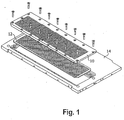
- Figure 1 shows an unassembled view of a fill plate 10, stripper plate 12 and a top plate 14.
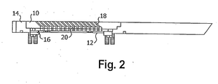
- Figure 2 shows an assembled view of the fill plate 10, stripper plate 12 and top plate 14, further comprising a stripper plate spacer and hold down 16, a cylindrical section 18 and a curved section 20.
- Figure 1 shows an unassembled view of a fill plate 10, stripper plate 12 and a top plate 14.
- Figure 2 shows an assembled view of the fill plate 10, stripper plate 12 and top plate 14, further comprising a stripper plate spacer and hold down 16, a cylindrical section 18 and a curved section 20.
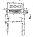
- Figure 3 shows a side view of the patty molding machine having an auger driver motor 30 an auger 32, knockouts 34 and a shear plate drive cylinder 36.
- Figure 4 shows a top view of an embodiment of the present invention, having a stripper plate drive 40, a fill and stripper plate assembly 42, a mold plate 44 and a draw bar 46.
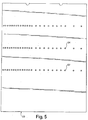
- Figure 5 shows a breather plate 60 having orifices 62 and 64 in the breather plate 60.
- Figure 6 shows the breather plate 70 having orifices 72 and 74.
- the channels are made up of a spherical section 76 intersecting a cylindrical section 78.
- Figure 7 further shows the orifice 74 having the spherical section 76 and a cylindrical section 78.
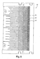
- Figure 8 shows the breather plate 80 having the orifices 82.
- Figure 9 shows the breather plate 90 having the orifices 92.
- Figure 10 shows a venturi 100 comprising a diameter 102 angle transition 104, throat length 106 and discharge 108.
- the present invention relates to fiber orientation technology.
- the fiber orientation technology drops pressure across the fill plate, aligns the fibers of meat so that the contraction of the muscle fiber that does take place is in a direction of choice controlling both bite and shrinkage.
- the fiber orientation technology provides a lower resistance to product flow using a venturi.
- the fiber orientation technology provides a better shear surface for a cleaner cut.
- the fiber orientation technology aligns the fibers in the fill hole so the shearing action disrupts as few muscle cells as possible.
- the fiber orientation technology decreases the total area of metal fill plate blocking the meat flow resulting in less direction change to the product which works the meat.
- the fiber orientation technology pulls the meat fiber through the fill hole instead of pushing using the principles of the venturi.
- Spherical geometry in fill or stripper plate creates venturi effects.
- a food molding machine has a mold plate and at least one mold cavity therein.
- a mold plate drive is connected to the mold plate for driving the mold plate along a given path, and a repetitive cycle, between a fill position and a discharge position.
- a food pump pumps a moldable food product through a fill passage connecting the food pump to the mold cavity when the mold plate is in the fill position.
- a fill plate, interposed in the fill passage immediately adjacent to the mold plate has a fill slot, fill horn, or multiplicity of fill orifices distributed in a predetermined pattern throughout an area aligned with the mold cavity when the mold plate is in fill position.
- the fill orifices define paths through the fill plate, wherein some of the paths each have a path portion obliquely angled or perpendicular to the fill side of the mold plate.
- the paths consist of spherical intersections or a curved structure.
- the side of the fill plate which is in contact with the stripper plate consists of a spherical hemisphere or curved structure has a diameter which is no greater than the choke flow for the liquid gas or solid used and is no less than the diameter of the connected cylindrical portion.
- the side of the fill plate which is in contact with the stripper consists of a spherical hemisphere or curved structure which has a diameter approximately 1.1 to 2.5 times greater than a cylindrical portion which intersect the top of the mold plate perpendicularly or at an angle of less than or equal to about +/-75 degrees, or about +/- 45 degrees in a preferred embodiment as measured from vertical in the longitudinal direction of the mold plate.
- a "venturi" condition is created.
- intersections between cylinder and spheres or curved structures create transitions which can be manufactured whose geometry approaches a venturi style system. It is preferred to have a sharper edge from the edge to the hole. To get a perfect edge it is preferred to sharpen with a grinder.
- the fill plate is chrome coated on the side adjacent to the stripper plate with a material significantly harder than the fill plate material. This is because the stripper plate wears out.
- the piece is approximately 39 Rockwell C. It becomes approximately 60-65 Rockwell C.
- the material is applied in a thickness to facilitate a surface which cuts the food product upon movement of a stripper plate. The material goes from 1/1000 th of an inch to about 10/1000 th of an inch with the chrome. A cutting hemisphere into bottom of plate, with a cylinder.
- a stripper plate is interposed in the fill passage immediately adjacent to the fill plate.
- the stripper plate is movable between the fill and discharge locations.
- the stripper plate has a multiplicity of fill openings aligned one-for-one with the fill orifices in the fill plate when the stripper plate is in fill position.
- a stripper plate drive is synchronized with the mold plate drive, such that the movement of the stripper plate facilitates the cutting of the meat product, which was pushed through the fill plate by the food pump.
- the stripper plate drive moves the stripper plate to its discharge position, in each mold cycle, before the mold plate moves appreciably toward the discharge location.
- the stripper plate drive maintains the stripper plate in the discharge position until the mold plate cavity is displaced beyond the fill orifices.
- the fill paths can be in a direction to the front, vertical or rear of the machine. All fill paths consist of a hemispherical shape which is intersected by a cylindrical shape at an angle less or equal to about +/- 75 degrees of vertical, and preferably about +/- 45 degrees of vertical.
- a spherical geometry feeding into a circular cross section creates a product velocity increase while maintaining more consistent pressure on the food product.
- a sphere has the following properties:
Description
- The present invention relates to an apparatus for creating a venturi effect in a food product molding machine. The venturi effect accelerates food product in order to cause the product to be stretched aligning the fibers of the product.
- Current forming technology relies on high pressure, speed and complicated material flow pathways which produce a product lacking in quality. High pressure works the meat cells, the higher the pressure the more massaging or squeezing of the meat cells takes place. High speed combined with a complicated flow path massages and works the meat product, releasing myosin/actin from the cells causing the muscle fiber to bind together and contract (protein bind). The contraction takes place during high heat application as in cooking. The action of the meat fiber is to contract in length, this contraction combined with protein bind not only shortens the muscle fiber which if not controlled causes odd cook shapes but a rubber like texture with a tough bite.
- In muscle, actin is the major component of thin filaments, which together with the motor protein myosin (which forms thick filaments), are arranged into actomyosin myofibrils. These fibrils comprise the mechanism of muscle contraction. Using the hydrolysis of ATP for energy, myosin heads undergo a cycle during which they attach to thin filaments, exerting a tension, and then depending on the load, perform a power stroke that causes the thin filaments to slide past, shortening the muscle.
- Muscle fibril structure is measured from micrometers to several millimeters in length. These fibril structures are bundled together to form muscles. Myofibril proteins are the largest group and probably more is known about these proteins than any other. In muscle cells actin is the scaffold on which myosin proteins generate force to support muscle contraction. Myosin is the major protein that is extracted from the muscle cells by mechanical means.
- An important purpose of tumbling and massaging is to solubiliize and extract myofibril proteins to produce a protein exudate on the surface of the meat. The exudates bind the formed pieces together upon heating. Binding strength also increases with increased massaging or blending time. This is due to increased exudate formation on the surface of the meat. Crude myosin extraction is increased with increased blending time.
- Grinding/chopping utilizes the concept of rupturing the cell to release protein. This mechanical chopping or shearing takes place at the shear/fill plate hole. This process extracts myosin from muscle cells.
- Mixing, utilizes friction and kinetic energy to release protein exudate. Fill hole shape and spacing can cause dead spots and turbulence in the meat flow. This change of direction is a form of mixing and massaging. This is another process, which extracts myosin from muscle cells.
- Massaging takes place almost anywhere meat comes in contact with processing equipment and is moved or has a change of direction via pressure. This is also a procedure which involves extracting myosin from muscle cells.
-
US4356595 describes a known food patty molding method and apparatus, utilizing a cyclically driven mold plate containing one or more mold cavities, in which the fill passage connecting the food pump to the mold cavity has a cross sectional area, immediately adjacent the mold plate fill position, encompassing the entire mold cavity surface area. In one embodiment the fill passage comprises a multiplicity of orifices. - The present invention provides a food molding machine as defined in appended claim 1.
- It is an object of the present invention for the fiber orientation technology to reduce the release and mixing of myosin with actin. It is an object of the present invention for the fiber orientation technology to control orientation of the fiber. It is an object of the present invention for the fiber orientation technology to provide less myosin activity resulting in a better bite/bind and control over the final cook shape.
- The present invention relates to an apparatus for accelerating food product in order to cause the product to be stretched aligning the fibers of the product. It is an object of the present invention for a hole or orifice to change size from a larger to a smaller diameter with vertical or concave sides. The principle has design similarities to a venturi. It is referred to as a nozzle, venturi, orifice, or a restriction to flow which results in product acceleration with a corresponding pressure drop through the orifice.
- By reducing the cross-sectional area of a tube through which a substance passes, the velocity is increased. This is the principle of Conservation of Mass. When the velocity increases the pressure of the material is reduced. This is the principle of the Conservation of Energy.
- For every liquid, there is a ratio between the cross-sectional area (C) and the cross-sectional area (c) through which velocity can only be increased by reducing temperature or increasing pressure. Although ground meat is not a homogeneous liquid, the same concepts still apply. It is impossible to attain venturi effect unless there is a transition between the orifices and the small orifice has a finite length.
- A venturi allows a smooth transition from a larger orifice to a smaller one. This transition minimizes flow transitions and thereby reduces restrictions in the system. The transition minimizes energy loss and supports fiber alignment.
- The transition in a venturi is extremely difficult to create in a production tooling environment. As a result, using the geometric properties of a sphere or similar shape allows the ability to obtain many of the venturi effect properties using standard production practices.
- All points on a sphere are the same distance from a fixed point. Contours and plane sections of spheres are circles. Spheres have the same width and girth. Spheres have maximum volume with minimum surface area. All of the above properties allow meat to flow with minimum interruptions. There are no static or dead zones. No matter what angle the cylinder intersects the sphere, the cross section is always a perfect circle.
- It is an object of the present invention to increase food product velocity forcing linear fiber alignment.
- It is an object of the present invention to have spherical geometry in breather plate to create venturi effects.
- The present invention relates to a food molding machine having a breather plate. A breather plate normally has a thickness less than 4.7 mm ( 3/16") in the area of the breather holes. A breather plate is positioned adjacent to the mold plate and opposite the fill slot plate. The breather plate is designed to evacuate air from the patty cavities and collect and route excess food matter back to a food supply source. The breather plate contains various ports which allow evacuation of air and accumulation of excess food matter from the filled patty cavities. The ports feed into a channel of openings which is cut into the back side of the breather plate.
- A breather plate sits adjacent to the mold plate on the opposite side of the fill slot, and slideably engages the mold plate. The breather plate includes at least one air pressure release passage, wherein a plurality of small breather holes enable the cavities of the mold plate to fluidly communicate with the passage. The air passage enables air in the cavities to escape as the machine pumps the cavities full of meat. The mold cover plate is adjacent the breather plate and its associated passage.
- In the current breather plate designs there is a resistance to forming the patties wherein evacuate out of the holes in the breather plate. In the case of prior art breather plates, the orifices are cylindrical and vary in number of orifices and diameters.
- This air flow can be accelerated by using a system which will reduce the cylinder size. Using the equation from Bernoulli's law of A1V1=A2V2, the velocity is increased by reducing the cross sectional area.
- The typical way of accomplishing this is the use of a venturi nozzle. However, a venturi requires a gradual area reduction and a finite length throat. Given the restrictions of the plate thickness in the breathing area, it is not feasible to put current venturi designs in a breather plate.
- However, utilizing the properties of a sphere, the air can achieve acceleration by intersecting a cylinder with a sphere of a larger diameter.
- In a sphere pressure is equal in all directions. Therefore, when the sphere is intersected by a cylinder, the air will move in a direction coaxial with the cylinder at a high velocity. The impact on the meat particles in the breather system is greater because air moving at a higher velocity will generate more momentum.
- It is an object of the present invention to provide a venturi effect in the hole by creating a sphere to cylinder hole. This creates a venturi effect or a venturi pump. This accelerates the product through the hole. It is an object of the invention for this to create a self-cleaning breather plate. The spherical cut creates equal pressure in all directions. In an example, the breather plate orifice has a spherical hemisphere or curved structure which has a diameter which is no greater than the choke flow for the liquid gas or solid used and is no less than the diameter of the connected cylindrical portion. In an example, the spherical hemisphere or curved structure to have a diameter between 1.1 to 2.5 times greater than a cylindrical portion which intersects the same. It is preferred to have a sharper edge from the edge to the hole.
- The present invention relates to a food molding machine having a mold plate and at least one mold cavity therein. A mold plate drive is connected to the mold plate for driving the mold plate along a given path, and a repetitive cycle, between a fill position and a discharge position. A food pump is provided for pumping a moldable food product through a fill passage connecting the food pump to the mold cavity when the mold plate is in the fill position. A fill plate, interposed in the fill passage adjacent to the mold plate has a multiplicity of fill orifices distributed in a predetermined pattern throughout an area aligned with the mold cavity when the mold plate is in fill position. The fill orifices define paths through the fill plate, wherein some of the paths each have a path portion obliquely angled or perpendicular to the fill side of the mold plate. The paths comprise spherical intersections. It is an object of the present invention to have a spherical hemisphere or curved structure which has a diameter which is no greater than the choke flow for the liquid gas or solid used and is no less than the diameter of the connected cylindrical portion. In an example, the side of the fill plate which is in contact with the stripper plate comprises a spherical hemisphere or curved structure which has a diameter between approximately 1.1 to 2.5 times greater than a cylindrical portion which intersect the top of the mold plate perpendicularly or at an angle of less than or equal to about +/-75 degrees, or about +/- 45 degrees in a preferred embodiment as measured from vertical in the longitudinal direction of the mold plate. By a reduction in the diameter a "venturi" condition is created. By using spherical sections or a curved structure, intersections between cylinder and spheres or curved structures create transitions which can be manufactured whose geometry approaches a venturi style system. It is preferred to have a sharper edge from the edge to the hole.
- In an example, the fill plate is chrome coated on the side adjacent to the stripper plate with a material significantly harder than the fill plate material. This is because the stripper plate wears out. The piece is approximately 39 Rockwell C. It becomes approximately 60-65 Rockwell C. In an example, the material is applied in a thickness to facilitate a surface which cuts the food product upon movement of a stripper plate. The material goes from about l/1000th of an inch to about 10/1000th of an inch with the chrome. A cutting hemisphere into bottom of plate, with a cylinder.
- In an example, the stripper plate is interposed in the fill passage immediately adjacent to the fill plate. In an example, the stripper plate is movable between the fill and discharge locations. In an example, the stripper plate has a multiplicity of fill openings aligned one-for-one with the fill orifices in the fill plate when the stripper plate is in fill position. In an example, the stripper plate drive is synchronized with the mold plate drive, such that the movement of the stripper plate facilitates the cutting of the meat product, which was pushed through the fill plate by the food pump. In an example, the stripper plate drive moves the stripper plate to its discharge position, in each mold cycle, before the mold plate moves appreciably toward the discharge location. In an example, the stripper plate drive maintains the stripper plate in the discharge position until the mold plate cavity is displaced beyond the fill orifices.
- In an example, the fill paths are in a direction to the front, vertical or rear of the machine. In an example, all fill paths consist of a hemispherical shape which is intersected by a cylindrical shape at an angle less or equal to about +/- 75 degrees of vertical, and preferably about +/- 45 degrees of vertical.
- In an example, the apparatus has a spherical hemisphere or curved structure which has a diameter which is no greater than the choke flow for the liquid gas or solid used and is no less than the diameter of the connected cylindrical portion to create conditions to meat flow which maintain improved cell structure.
- It is an object of the present invention to use spherical geometry, with cylindrical intersections, and the ratio of the diameter of the sphere divided by the area of the cylinder to be approximately 1.1 to 2.5 to create conditions to meat flow which maintain improved cell structure.
- Irregular shapes do not have diameters, but they do have areas. For a given ratio of a linear item, the ratio becomes the square of the linear ratio. For curved and irregular shapes, the ratio of the initial area and the reduced area is from approximately 1.2 to 6.25.
- It is an object of the present invention to provide a venturi effect in the hole by creating a sphere to cylinder hole. This creates a venturi effect or a venturi pump. This accelerates the product through the hole. It is an object of the present invention for this to be used in a fill plate.
- It is an object of the present invention to provide a venturi effect in the hole by creating a sphere to cylinder hole. This creates a venturi effect or a venturi pump. This accelerates the product through the hole. It is an object of the present invention for this to be used in a stripper plate.
- It is an object of the present invention to provide a venturi effect in the hole by creating a sphere to cylinder hole. This creates a venturi effect or a venturi pump. This accelerates the product through the hole. It is an object of the present invention for this to be used in a breather plate.
-
-
Figure 1 is an unassembled view of a fill plate and stripper plate of the present invention. -
Figure 2 is an assembled view of a fill plate and stripper plate of the present invention. -
Figure 3 shows a side view of an embodiment of the invention. -
Figure 4 shows a top view of an embodiment of the invention. -
Figure 5 is a top view of the breather plate design of the present invention. -
Figure 6 is a side view of the breather plate design of the present invention. -
Figure 7 is a view of a single hole of the breather plate design of the present invention. -
Figure 8 is a top view of the breather plate design of the present invention. -
Figure 9 is a top view of the breather plate design of the present invention. -
Figure 10 is an illustration of a venturi. -
Figure 1 shows an unassembled view of afill plate 10,stripper plate 12 and atop plate 14. -
Figure 2 shows an assembled view of thefill plate 10,stripper plate 12 andtop plate 14, further comprising a stripper plate spacer and hold down 16, acylindrical section 18 and acurved section 20. - It is an object of the present invention to provide a venturi effect in the hole by creating a sphere to cylinder hole. This creates a venturi effect or a venturi pump. This accelerates the product through the hole. It is an object of the present invention for this to be used in a breather plate.
-
-
Figure 1 is an unassembled view of a fill plate and stripper plate of the present invention. -
Figure 2 is an assembled view of a fill plate and stripper plate of the present invention. -
Figure 3 shows a side view of an embodiment of the invention. -
Figure 4 shows a top view of an embodiment of the invention. -
Figure 5 is a top view of the breather plate design of the present invention. -
Figure 6 is a side view of the breather plate design of the present invention. -
Figure 7 is a view of a single hole of the breather plate design of the present invention. -
Figure 8 is a top view of the breather plate design of the present invention. -
Figure 9 is a top view of the breather plate design of the present invention. -
Figure 10 is an illustration of a venturi. -
Figure 1 shows an unassembled view of afill plate 10,stripper plate 12 and atop plate 14. -
Figure 2 shows an assembled view of thefill plate 10,stripper plate 12 andtop plate 14, further comprising a stripper plate spacer and hold down 16, acylindrical section 18 and acurved section 20. -
Figure 3 shows a side view of the patty molding machine having anauger driver motor 30 anauger 32,knockouts 34 and a shearplate drive cylinder 36. -
Figure 4 shows a top view of an embodiment of the present invention, having astripper plate drive 40, a fill andstripper plate assembly 42, amold plate 44 and adraw bar 46. -
Figure 5 shows abreather plate 60 havingorifices breather plate 60. -
Figure 6 shows thebreather plate 70 havingorifices spherical section 76 intersecting acylindrical section 78. -
Figure 7 further shows theorifice 74 having thespherical section 76 and acylindrical section 78. -
Figure 8 shows thebreather plate 80 having theorifices 82. -
Figure 9 shows thebreather plate 90 having theorifices 92. -
Figure 10 shows aventuri 100 comprising adiameter 102angle transition 104,throat length 106 anddischarge 108. - The present invention relates to fiber orientation technology. The fiber orientation technology drops pressure across the fill plate, aligns the fibers of meat so that the contraction of the muscle fiber that does take place is in a direction of choice controlling both bite and shrinkage. The fiber orientation technology provides a lower resistance to product flow using a venturi.
- The fiber orientation technology provides a better shear surface for a cleaner cut. The fiber orientation technology aligns the fibers in the fill hole so the shearing action disrupts as few muscle cells as possible. The fiber orientation technology decreases the total area of metal fill plate blocking the meat flow resulting in less direction change to the product which works the meat. The fiber orientation technology pulls the meat fiber through the fill hole instead of pushing using the principles of the venturi.
- All of these characteristics of fiber orientation technology reduce the release and mixing of myosin with actin, the net effect is a controlled orientation of the fiber, less myosin activity resulting in a better bite/bind and control over the final cook shape.
- Spherical geometry in fill or stripper plate creates venturi effects.
- A food molding machine has a mold plate and at least one mold cavity therein. A mold plate drive is connected to the mold plate for driving the mold plate along a given path, and a repetitive cycle, between a fill position and a discharge position. A food pump pumps a moldable food product through a fill passage connecting the food pump to the mold cavity when the mold plate is in the fill position. A fill plate, interposed in the fill passage immediately adjacent to the mold plate has a fill slot, fill horn, or multiplicity of fill orifices distributed in a predetermined pattern throughout an area aligned with the mold cavity when the mold plate is in fill position. The fill orifices define paths through the fill plate, wherein some of the paths each have a path portion obliquely angled or perpendicular to the fill side of the mold plate. The paths consist of spherical intersections or a curved structure. In an embodiment, the side of the fill plate which is in contact with the stripper plate consists of a spherical hemisphere or curved structure has a diameter which is no greater than the choke flow for the liquid gas or solid used and is no less than the diameter of the connected cylindrical portion. In an embodiment, the side of the fill plate which is in contact with the stripper consists of a spherical hemisphere or curved structure which has a diameter approximately 1.1 to 2.5 times greater than a cylindrical portion which intersect the top of the mold plate perpendicularly or at an angle of less than or equal to about +/-75 degrees, or about +/- 45 degrees in a preferred embodiment as measured from vertical in the longitudinal direction of the mold plate. By a reduction in the cross-sectional area a "venturi" condition is created. By using spherical sections or a curved structure, intersections between cylinder and spheres or curved structures create transitions which can be manufactured whose geometry approaches a venturi style system. It is preferred to have a sharper edge from the edge to the hole. To get a perfect edge it is preferred to sharpen with a grinder.
- In a preferred embodiment, the fill plate is chrome coated on the side adjacent to the stripper plate with a material significantly harder than the fill plate material. This is because the stripper plate wears out. The piece is approximately 39 Rockwell C. It becomes approximately 60-65 Rockwell C. The material is applied in a thickness to facilitate a surface which cuts the food product upon movement of a stripper plate. The material goes from 1/1000th of an inch to about 10/1000th of an inch with the chrome. A cutting hemisphere into bottom of plate, with a cylinder.
- A stripper plate is interposed in the fill passage immediately adjacent to the fill plate. The stripper plate is movable between the fill and discharge locations. The stripper plate has a multiplicity of fill openings aligned one-for-one with the fill orifices in the fill plate when the stripper plate is in fill position. A stripper plate drive is synchronized with the mold plate drive, such that the movement of the stripper plate facilitates the cutting of the meat product, which was pushed through the fill plate by the food pump. The stripper plate drive moves the stripper plate to its discharge position, in each mold cycle, before the mold plate moves appreciably toward the discharge location. The stripper plate drive maintains the stripper plate in the discharge position until the mold plate cavity is displaced beyond the fill orifices.
- The fill paths can be in a direction to the front, vertical or rear of the machine. All fill paths consist of a hemispherical shape which is intersected by a cylindrical shape at an angle less or equal to about +/- 75 degrees of vertical, and preferably about +/- 45 degrees of vertical.
- The use of spherical geometry, with cylindrical sections wherein the spherical hemisphere or curved structure which has a diameter which is no greater than the choke flow for the liquid gas or solid used and is no less than the diameter of the connected cylindrical portion creates conditions to meat flow which maintain improved cell structure.
- The use of spherical geometry, with cylindrical intersections, and the ratio of the diameter of the sphere divided by the diameter of the cylinder is approximately 1.1 to 2.5 creates conditions to meat flow which maintain improved cell structure.
- In
Figure 10 a fluid enters at the, left end of the tube. Using conservation of mass and conservation of energy principles the volume rate of flow must be equal at all points in the systems. (ρ1A1V1) = (ρ2A2V2). Since p is a constant, velocity is inversely proportional to cross sectional area. Also, a venturi requires a ramp of some finite distance and a throat which also has a finite distance. - A spherical geometry feeding into a circular cross section creates a product velocity increase while maintaining more consistent pressure on the food product. A sphere has the following properties:
- All points on a sphere are the same distance from a fixed point.

- Contours and plane sections of spheres are circles.
- Spheres have the same width and girth.
- Spheres have maximum volume with minimum surface area.
- These properties allow food products to flow with minimum interruptions. There are no static or dead zones.
- No matter what angle the cylinder intersects the sphere; the cross section is always a perfect circle.
- Pressure inside of a sphere is uniform in all directions.
- When food product is passed through a circular cross section of a sphere, the fact that pressure is uniform in a sphere creates forces which will be coaxial with the sphere. The reduction in area accelerates the food product through the cylindrical section of the fill plate. The acceleration has been shown empirically to align fibers in the primary direct of flow. Hence, there is fiber orientation.
Claims (1)
- A food molding machine, comprising:a mold plate (44) having at least one mold cavity therein, a mold plate drive being connected to the mold plate for driving the mold plate along a given path, in a repetitive cycle, between a fill position and a discharge position;a food pump for pumping a moldable food product;a fill passage connecting said food pump to said mold cavity when said mold plate is in said fill position;a fill plate (42), interposed in said fill passage adjacent to said mold plate, and a breather plate (70);characterised by a multiplicity of breather plate orifices (72, 74) distributed in a predetermined pattern throughout an area of said breather plate,wherein each of said orifices (72, 74) has the shape of a sphere section (76) intersected by a cylinder (78) to create a Venturi effect.
Applications Claiming Priority (7)
| Application Number | Priority Date | Filing Date | Title |
|---|---|---|---|
| US13/199,910 US8985993B2 (en) | 2011-09-12 | 2011-09-12 | Fiber orienting technology |
| US13/374,423 US9713341B2 (en) | 2011-09-12 | 2011-12-27 | Food patty |
| US13/374,422 US9022772B2 (en) | 2011-09-12 | 2011-12-27 | Fiber orienting technology for a fill plate |
| US13/374,421 US9161549B2 (en) | 2011-09-12 | 2011-12-27 | Fiber orienting technology for a breather plate |
| US13/374,417 US9089242B2 (en) | 2011-09-12 | 2011-12-28 | Fiber orienting technology for a grinding machine |
| US13/374,441 US20130062371A1 (en) | 2011-09-12 | 2011-12-29 | System and method for creating a venturi effect within an orifice |
| PCT/US2012/000397 WO2013039552A1 (en) | 2011-09-12 | 2012-09-12 | Venturi effect technology on a food product molding machine |
Publications (3)
| Publication Number | Publication Date |
|---|---|
| EP2755491A1 EP2755491A1 (en) | 2014-07-23 |
| EP2755491A4 EP2755491A4 (en) | 2015-12-09 |
| EP2755491B1 true EP2755491B1 (en) | 2020-05-13 |
Family
ID=47883593
Family Applications (5)
| Application Number | Title | Priority Date | Filing Date |
|---|---|---|---|
| EP12831539.7A Active EP2755507B1 (en) | 2011-09-12 | 2012-09-12 | System and method for creating a venturi effect within an orifice |
| EP22188983.5A Pending EP4140309A1 (en) | 2011-09-12 | 2012-09-12 | System and method for creating a venturi effect within an orifice |
| EP12832471.2A Pending EP2755766A4 (en) | 2011-09-12 | 2012-09-12 | Fiber orienting technology for a grinding machine |
| EP12832228.6A Pending EP2755506A4 (en) | 2011-09-12 | 2012-09-12 | Improved formed food product |
| EP12832307.8A Active EP2755491B1 (en) | 2011-09-12 | 2012-09-12 | Venturi effect technology on a food product molding machine |
Family Applications Before (4)
| Application Number | Title | Priority Date | Filing Date |
|---|---|---|---|
| EP12831539.7A Active EP2755507B1 (en) | 2011-09-12 | 2012-09-12 | System and method for creating a venturi effect within an orifice |
| EP22188983.5A Pending EP4140309A1 (en) | 2011-09-12 | 2012-09-12 | System and method for creating a venturi effect within an orifice |
| EP12832471.2A Pending EP2755766A4 (en) | 2011-09-12 | 2012-09-12 | Fiber orienting technology for a grinding machine |
| EP12832228.6A Pending EP2755506A4 (en) | 2011-09-12 | 2012-09-12 | Improved formed food product |
Country Status (13)
| Country | Link |
|---|---|
| EP (5) | EP2755507B1 (en) |
| JP (9) | JP6078070B2 (en) |
| KR (6) | KR20210057200A (en) |
| CN (6) | CN104066343A (en) |
| AU (5) | AU2012309164B2 (en) |
| BR (5) | BR112014005593A2 (en) |
| CA (5) | CA3172877A1 (en) |
| ES (1) | ES2929611T3 (en) |
| MX (3) | MX367628B (en) |
| MY (2) | MY163941A (en) |
| RU (4) | RU2671175C2 (en) |
| WO (4) | WO2013039548A2 (en) |
| ZA (4) | ZA201402685B (en) |
Families Citing this family (3)
| Publication number | Priority date | Publication date | Assignee | Title |
|---|---|---|---|---|
| US20150196038A1 (en) * | 2014-01-13 | 2015-07-16 | Spherical Ip, Llc. | Grinder Assembly |
| CN106984413B (en) * | 2017-03-06 | 2018-08-28 | 中国农业科学院兰州畜牧与兽药研究所 | A kind of yak bone powder working apparatus |
| KR102335897B1 (en) * | 2020-10-23 | 2021-12-06 | 조선대학교산학협력단 | Composite material output apparatus for additive alignment control |
Family Cites Families (77)
| Publication number | Priority date | Publication date | Assignee | Title |
|---|---|---|---|---|
| US930920A (en) * | 1907-09-05 | 1909-08-10 | A J Deer Co | Meat-cutter. |
| US2823127A (en) * | 1956-02-24 | 1958-02-11 | Glenn B Gwilliam | Process for manufacturing steak product |
| GB869383A (en) * | 1958-01-30 | 1961-05-31 | Ofu Ofenbau Union Ges M B H | Method of and means for producing a gaseous heat carrier |
| US3640081A (en) * | 1969-04-02 | 1972-02-08 | Olin Mathieson | Hollow spherical ice bodies and method of making the same |
| US3852487A (en) * | 1969-08-28 | 1974-12-03 | Lever Brothers Ltd | Meat paste product and process for preparing same |
| GB1332133A (en) * | 1969-09-25 | 1973-10-03 | Beloit Corp | Method of film or sheet extrusion coating and forming |
| US3793466A (en) * | 1971-06-11 | 1974-02-19 | Lever Brothers Ltd | Process for preparing a restructured meat product |
| US3903315A (en) * | 1971-07-20 | 1975-09-02 | Lever Brothers Ltd | Process for making a restructured meat product |
| US3762658A (en) * | 1971-12-10 | 1973-10-02 | J Barnes | Meat cutting and extruding device |
| JPS5646806B2 (en) * | 1974-10-22 | 1981-11-05 | ||
| US3928641A (en) * | 1974-10-29 | 1975-12-23 | Ralston Purina Co | Method of collecting protein filaments |
| US4272864A (en) * | 1979-03-29 | 1981-06-16 | Holly Harry H | Method for making food patty |
| US4361588A (en) * | 1980-07-30 | 1982-11-30 | Nutrisearch Company | Fabricated food products from textured protein particles |
| US4356595A (en) * | 1980-11-07 | 1982-11-02 | Formax, Inc. | Method and apparatus for molding food patties |
| US4372008A (en) * | 1981-04-23 | 1983-02-08 | Formax, Inc. | Food patty molding machine with multi-orifice fill passage and stripper plate |
| US4541143A (en) * | 1982-11-23 | 1985-09-17 | Holly Systems, Inc. | Method and apparatus for forming a patty to accommodate tissue fiber flow |
| US4535505A (en) * | 1982-11-23 | 1985-08-20 | Holly Systems, Inc. | Method and apparatus for forming a patty to accommodate tissue fiber flow |
| EP0140898B1 (en) * | 1983-01-11 | 1989-06-28 | Ultimate Technologies, Inc. | A food patty with improved void structure, shape, and strength and method and apparatus for forming said patty |
| US4608731A (en) * | 1983-01-11 | 1986-09-02 | Holly Systems, Inc. | Food patty with improved void structure, shape, and strength and method and apparatus for forming said patty |
| SU1175519A1 (en) * | 1984-01-02 | 1985-08-30 | Фрунзенский политехнический институт | Contact tray for mass-transfer apparatus |
| US4716953A (en) * | 1986-05-13 | 1988-01-05 | Burnswick Industrial Supply Co. | Vent plug |
| US4810514A (en) * | 1986-10-22 | 1989-03-07 | Board Of Regents Acting For And On Behalf Of Oklahoma State University | Method of realigning fibers in manufacturing meat products |
| US4910040A (en) * | 1987-02-20 | 1990-03-20 | Horizons International Foods, Inc. | Method and protein product having aligned fibers |
| US4832593A (en) * | 1988-01-25 | 1989-05-23 | Husky Injection Molding Systems Ltd. | Large nozzle for hot runner mold |
| US4821376A (en) * | 1988-06-02 | 1989-04-18 | Formax, Inc. | Seal-off for food patty molding machine with multi-orifice fill passage and stripper plate |
| CN2039508U (en) * | 1988-09-15 | 1989-06-21 | 王宝林 | Apparatus for manufacturing imitative meat of livestock and fowl |
| US4872241A (en) * | 1988-10-31 | 1989-10-10 | Formax, Inc. | Patty molding mechanism for fibrous food product |
| KR0170770B1 (en) * | 1989-05-16 | 1999-01-15 | 이마나가 후미호 | Method and its apparatus of manufacturing fibrous fish or shellfish 'neriseihin' product |
| JPH03168149A (en) * | 1989-11-28 | 1991-07-19 | Matsushita Electric Ind Co Ltd | Nozzle apparatus for jet stream apparatus |
| FR2657489A1 (en) | 1990-01-19 | 1991-07-26 | Egide Sa | Device, such as plasma generator, with sequential flow of fluids |
| US5160290A (en) * | 1990-12-11 | 1992-11-03 | Richburg James B | Meat deboning apparatus and method |
| US5251829A (en) * | 1991-02-13 | 1993-10-12 | Weiler And Company, Inc. | Bone collector assembly for a meat grinder |
| US5443214A (en) * | 1991-02-13 | 1995-08-22 | Weiler And Company, Inc. | Hard material collector assembly for a grinder |
| CN1060016A (en) * | 1991-08-15 | 1992-04-08 | 童世英 | Hollow fluffy protein fibre dried meat making method |
| CN2146123Y (en) * | 1992-11-14 | 1993-11-17 | 山西农业大学 | Sausage filling or stuffing machine for forming preserved meat |
| RU2053853C1 (en) * | 1993-01-11 | 1996-02-10 | Минское экспериментально-конструкторское бюро машиностроения | Cutting mechanism of gyroscope |
| CN2156943Y (en) * | 1993-04-29 | 1994-02-23 | 孙绍波 | Fluidized powder self-suction type powder feeder for spray pistol |
| EP0720816B1 (en) * | 1995-01-04 | 1999-10-27 | Unilever Plc | Method of manufacturing a food product |
| GB9509585D0 (en) * | 1995-05-11 | 1995-07-05 | Matthews Bernard Plc | Method and apparatus for making an extruded meat product |
| US5713519A (en) * | 1995-07-21 | 1998-02-03 | Minnesota Mining And Manufacturing Company | Fluid spraying system |
| IT1279636B1 (en) * | 1995-09-21 | 1997-12-16 | Evolution Srl | GRINDING UNIT FOR AN INDUSTRIAL MEAT MINCER |
| JPH10276667A (en) * | 1997-04-04 | 1998-10-20 | Togami Electric Mfg Co Ltd | Mincing machine, transporting device therefor and transportation of material to be processed in mincing machine |
| IL121786A (en) * | 1997-09-17 | 2000-02-29 | Tivall 1993 Ltd | Fibrous food product and method and device for its production |
| DE19802782C2 (en) * | 1998-01-26 | 2002-10-24 | Eberhard Haack | Perforated disc-knife combination for cutting sets of meat grinders |
| US6319538B1 (en) * | 1999-01-26 | 2001-11-20 | Jac Pac Foods, Ltd. | Method of producing a clamshell shaped meatball |
| CN2373163Y (en) * | 1999-05-14 | 2000-04-12 | 重庆钢铁设计研究院 | Venturi |
| ATE296130T1 (en) * | 1999-05-28 | 2005-06-15 | Novo Nordisk As | METHOD AND SYSTEM FOR PRODUCING A PLASTIC NEEDLE |
| WO2002019285A2 (en) * | 2000-05-23 | 2002-03-07 | Munroe Chirnomas | Method and apparatus for including article identification in an article handling device |
| US6379738B1 (en) * | 1999-11-16 | 2002-04-30 | Nestec S.A. | Meat emulsion product |
| US6416314B1 (en) * | 2000-04-08 | 2002-07-09 | Formax, Inc. | Patty-forming mold plate assembly |
| JP2001299198A (en) | 2000-04-21 | 2001-10-30 | Teramoto Engineering:Kk | Mincing plate |
| US6604935B2 (en) * | 2001-09-28 | 2003-08-12 | Tomahawk Manufacturing, Inc. | Double row molding apparatus |
| US7887838B2 (en) * | 2002-01-18 | 2011-02-15 | Banner Pharmacaps, Inc. | Non-gelatin film and method and apparatus for producing same |
| US20060092758A1 (en) * | 2002-07-03 | 2006-05-04 | Ellmers Peter H | Fluid mixing venturi |
| JP3738754B2 (en) * | 2002-07-11 | 2006-01-25 | 日産自動車株式会社 | Aluminum plating structural member for electrodeposition coating and manufacturing method thereof |
| US7488171B2 (en) * | 2002-10-25 | 2009-02-10 | R.J. Reynolds Tobacco Company | Gas micro burner |
| US7163391B2 (en) | 2003-08-20 | 2007-01-16 | Formax, Inc. | Molding apparatus for forming food patties having top and bottom surface contours |
| WO2005041698A2 (en) * | 2003-10-28 | 2005-05-12 | Patriot Universal Holdings, Llc. | A method and system for controlling product flow on a food product molding machine |
| US20050095345A1 (en) * | 2003-11-04 | 2005-05-05 | Schillinger John A. | Soy products and soy product production methods and apparatus |
| RU2267358C1 (en) * | 2004-07-12 | 2006-01-10 | Государственное образовательное учреждение высшего профессионального образования Воронежская государственная технологическая академия | Trimming grid for raw meat-and-bone material grinding apparatus |
| CN101010543A (en) * | 2004-08-18 | 2007-08-01 | 乔治洛德方法研究和开发液化空气有限公司 | Method and apparatus for injecting a gas into a two-phase stream |
| CN2753158Y (en) * | 2004-12-22 | 2006-01-25 | 哈尔滨商业大学 | Shashlik automatic-filling-metering forming mechanism |
| US7862330B2 (en) * | 2005-04-22 | 2011-01-04 | Formax, Inc. | Angled fill ports and seal-off arrangement for patty-forming apparatus |
| UA14451U (en) * | 2005-11-24 | 2006-05-15 | Mykhailo Vasyliovych Yefremov | A bushing plate for making mineral fibre |
| CN1824389A (en) * | 2006-01-26 | 2006-08-30 | 苏继香 | Pneumatic crushing machine gaseous material mixing jetting type charging technology |
| CN2890712Y (en) * | 2006-02-22 | 2007-04-18 | 孙海波 | Power-less indoor air purifier |
| CN101099581A (en) * | 2006-07-06 | 2008-01-09 | 李德一 | Method for making fishbone-taken-off fish piece and food made from fishbone-taken-off fish piece |
| US7591644B2 (en) * | 2006-09-15 | 2009-09-22 | Formax, Inc. | Counter-balanced mold plate for food patty molding machine |
| CN102026553A (en) * | 2006-12-28 | 2011-04-20 | 索莱有限责任公司 | Ground meat and meat analog compositions having improved nutritional properties |
| EA010227B1 (en) * | 2007-03-29 | 2008-06-30 | Общество С Ограниченной Ответственностью "Марс" | Foodstuff imitating pieces of natural meat flesh and method for preparing thereof |
| US20080248167A1 (en) * | 2007-04-05 | 2008-10-09 | Solae, Llc | Processed Meat Products Comprising Structured Protein Products |
| US20080254167A1 (en) * | 2007-04-10 | 2008-10-16 | Solae, Llc | Seafood Compositions Comprising Structured Protein Products |
| EA016531B1 (en) * | 2007-07-19 | 2012-05-30 | ДСМ АйПи АССЕТС Б.В. | Improved method for the treatment of food, feed and agricultural products with a polyene antifungal compound |
| US20090202293A1 (en) * | 2008-02-12 | 2009-08-13 | Peter Kajuch | Air induction showerhead ball joint |
| CN101278710B (en) * | 2008-05-19 | 2011-04-20 | 谢安国 | Bionic meat made from wheat specially matched with instant noodles catsup and method of preparing the same |
| CN101411346A (en) * | 2008-11-28 | 2009-04-22 | 中山职业技术学院 | Power transmission device of full-automatic muddy flesh processor |
| ES2432617T3 (en) * | 2009-07-06 | 2013-12-04 | Willy A. Bachofen Ag | Ball mill with stirrer |
-
2012
- 2012-09-12 RU RU2014114476A patent/RU2671175C2/en active
- 2012-09-12 CA CA3172877A patent/CA3172877A1/en active Pending
- 2012-09-12 MY MYPI2014000711A patent/MY163941A/en unknown
- 2012-09-12 EP EP12831539.7A patent/EP2755507B1/en active Active
- 2012-09-12 KR KR1020217013558A patent/KR20210057200A/en not_active IP Right Cessation
- 2012-09-12 ES ES12831539T patent/ES2929611T3/en active Active
- 2012-09-12 JP JP2014530651A patent/JP6078070B2/en active Active
- 2012-09-12 MX MX2014002926A patent/MX367628B/en active IP Right Grant
- 2012-09-12 EP EP22188983.5A patent/EP4140309A1/en active Pending
- 2012-09-12 KR KR1020147009751A patent/KR20140061531A/en active Application Filing
- 2012-09-12 CN CN201280055504.2A patent/CN104066343A/en active Pending
- 2012-09-12 EP EP12832471.2A patent/EP2755766A4/en active Pending
- 2012-09-12 AU AU2012309164A patent/AU2012309164B2/en active Active
- 2012-09-12 EP EP12832228.6A patent/EP2755506A4/en active Pending
- 2012-09-12 RU RU2014114475A patent/RU2623235C2/en active
- 2012-09-12 CN CN201280055498.0A patent/CN104023563A/en active Pending
- 2012-09-12 BR BR112014005593A patent/BR112014005593A2/en not_active Application Discontinuation
- 2012-09-12 KR KR1020147009743A patent/KR102212542B1/en active IP Right Grant
- 2012-09-12 CA CA2848389A patent/CA2848389C/en active Active
- 2012-09-12 CN CN201810365897.6A patent/CN108576164B/en active Active
- 2012-09-12 CA CA2848399A patent/CA2848399C/en active Active
- 2012-09-12 AU AU2012309163A patent/AU2012309163A1/en not_active Abandoned
- 2012-09-12 JP JP2014530649A patent/JP2014526260A/en active Pending
- 2012-09-12 BR BR112014005590A patent/BR112014005590A2/en not_active Application Discontinuation
- 2012-09-12 WO PCT/US2012/000392 patent/WO2013039548A2/en active Application Filing
- 2012-09-12 BR BR112014005594A patent/BR112014005594A2/en not_active Application Discontinuation
- 2012-09-12 MX MX2014002927A patent/MX2014002927A/en unknown
- 2012-09-12 AU AU2012309165A patent/AU2012309165B2/en active Active
- 2012-09-12 WO PCT/US2012/000390 patent/WO2013039546A1/en active Application Filing
- 2012-09-12 EP EP12832307.8A patent/EP2755491B1/en active Active
- 2012-09-12 MX MX2014002928A patent/MX2014002928A/en unknown
- 2012-09-12 RU RU2014114445A patent/RU2627497C2/en active
- 2012-09-12 WO PCT/US2012/000397 patent/WO2013039552A1/en active Application Filing
- 2012-09-12 CN CN201710866462.5A patent/CN107646953B/en active Active
- 2012-09-12 CA CA2848396A patent/CA2848396C/en active Active
- 2012-09-12 WO PCT/US2012/000391 patent/WO2013039547A1/en active Application Filing
- 2012-09-12 KR KR1020147009745A patent/KR102212546B1/en active IP Right Grant
- 2012-09-12 KR KR1020237000156A patent/KR102616316B1/en active IP Right Grant
- 2012-09-12 KR KR1020147009663A patent/KR102212584B1/en active IP Right Grant
- 2012-09-12 BR BR122019014804-0A patent/BR122019014804B1/en active IP Right Grant
- 2012-09-12 JP JP2014530648A patent/JP2014531207A/en active Pending
- 2012-09-12 RU RU2014114477A patent/RU2609406C2/en active
- 2012-09-12 CN CN201280055540.9A patent/CN104080538B/en active Active
- 2012-09-12 MY MYPI2014000710A patent/MY169633A/en unknown
- 2012-09-12 CA CA2848404A patent/CA2848404C/en active Active
- 2012-09-12 BR BR112014005587A patent/BR112014005587A2/en not_active Application Discontinuation
- 2012-09-12 CN CN201280055488.7A patent/CN104080347B/en active Active
- 2012-09-12 JP JP2014530650A patent/JP6078069B2/en active Active
- 2012-09-12 AU AU2012309169A patent/AU2012309169B9/en active Active
-
2014
- 2014-04-11 ZA ZA2014/02685A patent/ZA201402685B/en unknown
- 2014-04-11 ZA ZA2014/02682A patent/ZA201402682B/en unknown
- 2014-04-11 ZA ZA2014/02684A patent/ZA201402684B/en unknown
- 2014-04-11 ZA ZA2014/02683A patent/ZA201402683B/en unknown
-
2017
- 2017-04-19 JP JP2017082439A patent/JP2017131241A/en active Pending
- 2017-05-31 JP JP2017107818A patent/JP6794314B2/en active Active
-
2018
- 2018-01-03 AU AU2018200049A patent/AU2018200049B2/en active Active
-
2019
- 2019-09-27 JP JP2019177397A patent/JP2020014472A/en active Pending
-
2021
- 2021-10-11 JP JP2021166791A patent/JP2022016436A/en active Pending
-
2022
- 2022-12-28 JP JP2022212282A patent/JP2023052173A/en active Pending
Non-Patent Citations (1)
| Title |
|---|
| None * |
Also Published As
Similar Documents
| Publication | Publication Date | Title |
|---|---|---|
| US9604223B2 (en) | Fiber orienting technology for a grinding machine | |
| US8979522B2 (en) | Fiber orienting technology for a grinding machine | |
| EP2755491B1 (en) | Venturi effect technology on a food product molding machine | |
| US11172686B2 (en) | Venturi effect technology on a food product molding machine | |
| US9161549B2 (en) | Fiber orienting technology for a breather plate | |
| US20150196038A1 (en) | Grinder Assembly | |
| US20150209737A1 (en) | Fiber orienting technology for a fill plate | |
| US9022772B2 (en) | Fiber orienting technology for a fill plate | |
| US20130062371A1 (en) | System and method for creating a venturi effect within an orifice | |
| US9713341B2 (en) | Food patty |
Legal Events
| Date | Code | Title | Description |
|---|---|---|---|
| PUAI | Public reference made under article 153(3) epc to a published international application that has entered the european phase |
Free format text: ORIGINAL CODE: 0009012 |
|
| 17P | Request for examination filed |
Effective date: 20140409 |
|
| AK | Designated contracting states |
Kind code of ref document: A1 Designated state(s): AL AT BE BG CH CY CZ DE DK EE ES FI FR GB GR HR HU IE IS IT LI LT LU LV MC MK MT NL NO PL PT RO RS SE SI SK SM TR |
|
| DAX | Request for extension of the european patent (deleted) | ||
| RA4 | Supplementary search report drawn up and despatched (corrected) |
Effective date: 20151106 |
|
| RIC1 | Information provided on ipc code assigned before grant |
Ipc: B02C 18/36 20060101ALI20151102BHEP Ipc: A22C 17/00 20060101ALI20151102BHEP Ipc: A22C 7/00 20060101AFI20151102BHEP |
|
| STAA | Information on the status of an ep patent application or granted ep patent |
Free format text: STATUS: EXAMINATION IS IN PROGRESS |
|
| 17Q | First examination report despatched |
Effective date: 20190314 |
|
| GRAP | Despatch of communication of intention to grant a patent |
Free format text: ORIGINAL CODE: EPIDOSNIGR1 |
|
| STAA | Information on the status of an ep patent application or granted ep patent |
Free format text: STATUS: GRANT OF PATENT IS INTENDED |
|
| INTG | Intention to grant announced |
Effective date: 20191202 |
|
| GRAS | Grant fee paid |
Free format text: ORIGINAL CODE: EPIDOSNIGR3 |
|
| GRAA | (expected) grant |
Free format text: ORIGINAL CODE: 0009210 |
|
| STAA | Information on the status of an ep patent application or granted ep patent |
Free format text: STATUS: THE PATENT HAS BEEN GRANTED |
|
| AK | Designated contracting states |
Kind code of ref document: B1 Designated state(s): AL AT BE BG CH CY CZ DE DK EE ES FI FR GB GR HR HU IE IS IT LI LT LU LV MC MK MT NL NO PL PT RO RS SE SI SK SM TR |
|
| REG | Reference to a national code |
Ref country code: GB Ref legal event code: FG4D |
|
| REG | Reference to a national code |
Ref country code: CH Ref legal event code: EP |
|
| REG | Reference to a national code |
Ref country code: DE Ref legal event code: R096 Ref document number: 602012070123 Country of ref document: DE |
|
| REG | Reference to a national code |
Ref country code: AT Ref legal event code: REF Ref document number: 1269021 Country of ref document: AT Kind code of ref document: T Effective date: 20200615 |
|
| REG | Reference to a national code |
Ref country code: CH Ref legal event code: NV Representative=s name: DENNEMEYER AG, CH |
|
| REG | Reference to a national code |
Ref country code: NL Ref legal event code: FP |
|
| REG | Reference to a national code |
Ref country code: LT Ref legal event code: MG4D |
|
| PG25 | Lapsed in a contracting state [announced via postgrant information from national office to epo] |
Ref country code: SE Free format text: LAPSE BECAUSE OF FAILURE TO SUBMIT A TRANSLATION OF THE DESCRIPTION OR TO PAY THE FEE WITHIN THE PRESCRIBED TIME-LIMIT Effective date: 20200513 Ref country code: LT Free format text: LAPSE BECAUSE OF FAILURE TO SUBMIT A TRANSLATION OF THE DESCRIPTION OR TO PAY THE FEE WITHIN THE PRESCRIBED TIME-LIMIT Effective date: 20200513 Ref country code: NO Free format text: LAPSE BECAUSE OF FAILURE TO SUBMIT A TRANSLATION OF THE DESCRIPTION OR TO PAY THE FEE WITHIN THE PRESCRIBED TIME-LIMIT Effective date: 20200813 Ref country code: GR Free format text: LAPSE BECAUSE OF FAILURE TO SUBMIT A TRANSLATION OF THE DESCRIPTION OR TO PAY THE FEE WITHIN THE PRESCRIBED TIME-LIMIT Effective date: 20200814 Ref country code: FI Free format text: LAPSE BECAUSE OF FAILURE TO SUBMIT A TRANSLATION OF THE DESCRIPTION OR TO PAY THE FEE WITHIN THE PRESCRIBED TIME-LIMIT Effective date: 20200513 Ref country code: IS Free format text: LAPSE BECAUSE OF FAILURE TO SUBMIT A TRANSLATION OF THE DESCRIPTION OR TO PAY THE FEE WITHIN THE PRESCRIBED TIME-LIMIT Effective date: 20200913 Ref country code: PT Free format text: LAPSE BECAUSE OF FAILURE TO SUBMIT A TRANSLATION OF THE DESCRIPTION OR TO PAY THE FEE WITHIN THE PRESCRIBED TIME-LIMIT Effective date: 20200914 |
|
| PG25 | Lapsed in a contracting state [announced via postgrant information from national office to epo] |
Ref country code: LV Free format text: LAPSE BECAUSE OF FAILURE TO SUBMIT A TRANSLATION OF THE DESCRIPTION OR TO PAY THE FEE WITHIN THE PRESCRIBED TIME-LIMIT Effective date: 20200513 Ref country code: HR Free format text: LAPSE BECAUSE OF FAILURE TO SUBMIT A TRANSLATION OF THE DESCRIPTION OR TO PAY THE FEE WITHIN THE PRESCRIBED TIME-LIMIT Effective date: 20200513 Ref country code: BG Free format text: LAPSE BECAUSE OF FAILURE TO SUBMIT A TRANSLATION OF THE DESCRIPTION OR TO PAY THE FEE WITHIN THE PRESCRIBED TIME-LIMIT Effective date: 20200813 Ref country code: RS Free format text: LAPSE BECAUSE OF FAILURE TO SUBMIT A TRANSLATION OF THE DESCRIPTION OR TO PAY THE FEE WITHIN THE PRESCRIBED TIME-LIMIT Effective date: 20200513 |
|
| REG | Reference to a national code |
Ref country code: AT Ref legal event code: MK05 Ref document number: 1269021 Country of ref document: AT Kind code of ref document: T Effective date: 20200513 |
|
| PG25 | Lapsed in a contracting state [announced via postgrant information from national office to epo] |
Ref country code: AL Free format text: LAPSE BECAUSE OF FAILURE TO SUBMIT A TRANSLATION OF THE DESCRIPTION OR TO PAY THE FEE WITHIN THE PRESCRIBED TIME-LIMIT Effective date: 20200513 |
|
| PG25 | Lapsed in a contracting state [announced via postgrant information from national office to epo] |
Ref country code: RO Free format text: LAPSE BECAUSE OF FAILURE TO SUBMIT A TRANSLATION OF THE DESCRIPTION OR TO PAY THE FEE WITHIN THE PRESCRIBED TIME-LIMIT Effective date: 20200513 Ref country code: CZ Free format text: LAPSE BECAUSE OF FAILURE TO SUBMIT A TRANSLATION OF THE DESCRIPTION OR TO PAY THE FEE WITHIN THE PRESCRIBED TIME-LIMIT Effective date: 20200513 Ref country code: ES Free format text: LAPSE BECAUSE OF FAILURE TO SUBMIT A TRANSLATION OF THE DESCRIPTION OR TO PAY THE FEE WITHIN THE PRESCRIBED TIME-LIMIT Effective date: 20200513 Ref country code: DK Free format text: LAPSE BECAUSE OF FAILURE TO SUBMIT A TRANSLATION OF THE DESCRIPTION OR TO PAY THE FEE WITHIN THE PRESCRIBED TIME-LIMIT Effective date: 20200513 Ref country code: IT Free format text: LAPSE BECAUSE OF FAILURE TO SUBMIT A TRANSLATION OF THE DESCRIPTION OR TO PAY THE FEE WITHIN THE PRESCRIBED TIME-LIMIT Effective date: 20200513 Ref country code: EE Free format text: LAPSE BECAUSE OF FAILURE TO SUBMIT A TRANSLATION OF THE DESCRIPTION OR TO PAY THE FEE WITHIN THE PRESCRIBED TIME-LIMIT Effective date: 20200513 Ref country code: AT Free format text: LAPSE BECAUSE OF FAILURE TO SUBMIT A TRANSLATION OF THE DESCRIPTION OR TO PAY THE FEE WITHIN THE PRESCRIBED TIME-LIMIT Effective date: 20200513 Ref country code: SM Free format text: LAPSE BECAUSE OF FAILURE TO SUBMIT A TRANSLATION OF THE DESCRIPTION OR TO PAY THE FEE WITHIN THE PRESCRIBED TIME-LIMIT Effective date: 20200513 |
|
| REG | Reference to a national code |
Ref country code: DE Ref legal event code: R097 Ref document number: 602012070123 Country of ref document: DE |
|
| PG25 | Lapsed in a contracting state [announced via postgrant information from national office to epo] |
Ref country code: PL Free format text: LAPSE BECAUSE OF FAILURE TO SUBMIT A TRANSLATION OF THE DESCRIPTION OR TO PAY THE FEE WITHIN THE PRESCRIBED TIME-LIMIT Effective date: 20200513 Ref country code: SK Free format text: LAPSE BECAUSE OF FAILURE TO SUBMIT A TRANSLATION OF THE DESCRIPTION OR TO PAY THE FEE WITHIN THE PRESCRIBED TIME-LIMIT Effective date: 20200513 |
|
| PLBE | No opposition filed within time limit |
Free format text: ORIGINAL CODE: 0009261 |
|
| STAA | Information on the status of an ep patent application or granted ep patent |
Free format text: STATUS: NO OPPOSITION FILED WITHIN TIME LIMIT |
|
| 26N | No opposition filed |
Effective date: 20210216 |
|
| PG25 | Lapsed in a contracting state [announced via postgrant information from national office to epo] |
Ref country code: MC Free format text: LAPSE BECAUSE OF FAILURE TO SUBMIT A TRANSLATION OF THE DESCRIPTION OR TO PAY THE FEE WITHIN THE PRESCRIBED TIME-LIMIT Effective date: 20200513 |
|
| PG25 | Lapsed in a contracting state [announced via postgrant information from national office to epo] |
Ref country code: SI Free format text: LAPSE BECAUSE OF FAILURE TO SUBMIT A TRANSLATION OF THE DESCRIPTION OR TO PAY THE FEE WITHIN THE PRESCRIBED TIME-LIMIT Effective date: 20200513 |
|
| REG | Reference to a national code |
Ref country code: BE Ref legal event code: MM Effective date: 20200930 |
|
| PG25 | Lapsed in a contracting state [announced via postgrant information from national office to epo] |
Ref country code: LU Free format text: LAPSE BECAUSE OF NON-PAYMENT OF DUE FEES Effective date: 20200912 |
|
| PG25 | Lapsed in a contracting state [announced via postgrant information from national office to epo] |
Ref country code: BE Free format text: LAPSE BECAUSE OF NON-PAYMENT OF DUE FEES Effective date: 20200930 |
|
| PGFP | Annual fee paid to national office [announced via postgrant information from national office to epo] |
Ref country code: IE Payment date: 20211001 Year of fee payment: 10 |
|
| PG25 | Lapsed in a contracting state [announced via postgrant information from national office to epo] |
Ref country code: TR Free format text: LAPSE BECAUSE OF FAILURE TO SUBMIT A TRANSLATION OF THE DESCRIPTION OR TO PAY THE FEE WITHIN THE PRESCRIBED TIME-LIMIT Effective date: 20200513 Ref country code: MT Free format text: LAPSE BECAUSE OF FAILURE TO SUBMIT A TRANSLATION OF THE DESCRIPTION OR TO PAY THE FEE WITHIN THE PRESCRIBED TIME-LIMIT Effective date: 20200513 Ref country code: CY Free format text: LAPSE BECAUSE OF FAILURE TO SUBMIT A TRANSLATION OF THE DESCRIPTION OR TO PAY THE FEE WITHIN THE PRESCRIBED TIME-LIMIT Effective date: 20200513 |
|
| PG25 | Lapsed in a contracting state [announced via postgrant information from national office to epo] |
Ref country code: MK Free format text: LAPSE BECAUSE OF FAILURE TO SUBMIT A TRANSLATION OF THE DESCRIPTION OR TO PAY THE FEE WITHIN THE PRESCRIBED TIME-LIMIT Effective date: 20200513 |
|
| PG25 | Lapsed in a contracting state [announced via postgrant information from national office to epo] |
Ref country code: IE Free format text: LAPSE BECAUSE OF NON-PAYMENT OF DUE FEES Effective date: 20220912 |
|
| PGFP | Annual fee paid to national office [announced via postgrant information from national office to epo] |
Ref country code: NL Payment date: 20230928 Year of fee payment: 12 Ref country code: GB Payment date: 20230928 Year of fee payment: 12 |
|
| PGFP | Annual fee paid to national office [announced via postgrant information from national office to epo] |
Ref country code: FR Payment date: 20230922 Year of fee payment: 12 Ref country code: DE Payment date: 20230928 Year of fee payment: 12 |
|
| REG | Reference to a national code |
Ref country code: IE Ref legal event code: NE4A |
|
| PGFP | Annual fee paid to national office [announced via postgrant information from national office to epo] |
Ref country code: CH Payment date: 20231001 Year of fee payment: 12 |
|
| PG25 | Lapsed in a contracting state [announced via postgrant information from national office to epo] |
Ref country code: IE Free format text: LAPSE BECAUSE OF NON-PAYMENT OF DUE FEES Effective date: 20220912 |
|
| PGFP | Annual fee paid to national office [announced via postgrant information from national office to epo] |
Ref country code: IE Payment date: 20240221 Year of fee payment: 12 |
|
| PGRI | Patent reinstated in contracting state [announced from national office to epo] |
Ref country code: IE Effective date: 20240227 |