EP2755085B1 - Light source apparatus and projector - Google Patents
Light source apparatus and projector Download PDFInfo
- Publication number
- EP2755085B1 EP2755085B1 EP13198966.7A EP13198966A EP2755085B1 EP 2755085 B1 EP2755085 B1 EP 2755085B1 EP 13198966 A EP13198966 A EP 13198966A EP 2755085 B1 EP2755085 B1 EP 2755085B1
- Authority
- EP
- European Patent Office
- Prior art keywords
- light
- light source
- phosphor
- excitation light
- phosphor wheel
- Prior art date
- Legal status (The legal status is an assumption and is not a legal conclusion. Google has not performed a legal analysis and makes no representation as to the accuracy of the status listed.)
- Not-in-force
Links
Images


Classifications
-
- F—MECHANICAL ENGINEERING; LIGHTING; HEATING; WEAPONS; BLASTING
- F21—LIGHTING
- F21V—FUNCTIONAL FEATURES OR DETAILS OF LIGHTING DEVICES OR SYSTEMS THEREOF; STRUCTURAL COMBINATIONS OF LIGHTING DEVICES WITH OTHER ARTICLES, NOT OTHERWISE PROVIDED FOR
- F21V9/00—Elements for modifying spectral properties, polarisation or intensity of the light emitted, e.g. filters
- F21V9/08—Elements for modifying spectral properties, polarisation or intensity of the light emitted, e.g. filters for producing coloured light, e.g. monochromatic; for reducing intensity of light
-
- G—PHYSICS
- G03—PHOTOGRAPHY; CINEMATOGRAPHY; ANALOGOUS TECHNIQUES USING WAVES OTHER THAN OPTICAL WAVES; ELECTROGRAPHY; HOLOGRAPHY
- G03B—APPARATUS OR ARRANGEMENTS FOR TAKING PHOTOGRAPHS OR FOR PROJECTING OR VIEWING THEM; APPARATUS OR ARRANGEMENTS EMPLOYING ANALOGOUS TECHNIQUES USING WAVES OTHER THAN OPTICAL WAVES; ACCESSORIES THEREFOR
- G03B21/00—Projectors or projection-type viewers; Accessories therefor
- G03B21/14—Details
- G03B21/20—Lamp housings
- G03B21/2006—Lamp housings characterised by the light source
- G03B21/2033—LED or laser light sources
- G03B21/204—LED or laser light sources using secondary light emission, e.g. luminescence or fluorescence
-
- G—PHYSICS
- G03—PHOTOGRAPHY; CINEMATOGRAPHY; ANALOGOUS TECHNIQUES USING WAVES OTHER THAN OPTICAL WAVES; ELECTROGRAPHY; HOLOGRAPHY
- G03B—APPARATUS OR ARRANGEMENTS FOR TAKING PHOTOGRAPHS OR FOR PROJECTING OR VIEWING THEM; APPARATUS OR ARRANGEMENTS EMPLOYING ANALOGOUS TECHNIQUES USING WAVES OTHER THAN OPTICAL WAVES; ACCESSORIES THEREFOR
- G03B21/00—Projectors or projection-type viewers; Accessories therefor
- G03B21/14—Details
- G03B21/142—Adjusting of projection optics
-
- G—PHYSICS
- G03—PHOTOGRAPHY; CINEMATOGRAPHY; ANALOGOUS TECHNIQUES USING WAVES OTHER THAN OPTICAL WAVES; ELECTROGRAPHY; HOLOGRAPHY
- G03B—APPARATUS OR ARRANGEMENTS FOR TAKING PHOTOGRAPHS OR FOR PROJECTING OR VIEWING THEM; APPARATUS OR ARRANGEMENTS EMPLOYING ANALOGOUS TECHNIQUES USING WAVES OTHER THAN OPTICAL WAVES; ACCESSORIES THEREFOR
- G03B33/00—Colour photography, other than mere exposure or projection of a colour film
- G03B33/08—Sequential recording or projection
-
- H—ELECTRICITY
- H04—ELECTRIC COMMUNICATION TECHNIQUE
- H04N—PICTORIAL COMMUNICATION, e.g. TELEVISION
- H04N9/00—Details of colour television systems
- H04N9/12—Picture reproducers
- H04N9/31—Projection devices for colour picture display, e.g. using electronic spatial light modulators [ESLM]
- H04N9/3102—Projection devices for colour picture display, e.g. using electronic spatial light modulators [ESLM] using two-dimensional electronic spatial light modulators
- H04N9/3111—Projection devices for colour picture display, e.g. using electronic spatial light modulators [ESLM] using two-dimensional electronic spatial light modulators for displaying the colours sequentially, e.g. by using sequentially activated light sources
- H04N9/3114—Projection devices for colour picture display, e.g. using electronic spatial light modulators [ESLM] using two-dimensional electronic spatial light modulators for displaying the colours sequentially, e.g. by using sequentially activated light sources by using a sequential colour filter producing one colour at a time
-
- H—ELECTRICITY
- H04—ELECTRIC COMMUNICATION TECHNIQUE
- H04N—PICTORIAL COMMUNICATION, e.g. TELEVISION
- H04N9/00—Details of colour television systems
- H04N9/12—Picture reproducers
- H04N9/31—Projection devices for colour picture display, e.g. using electronic spatial light modulators [ESLM]
- H04N9/3141—Constructional details thereof
- H04N9/315—Modulator illumination systems
- H04N9/3158—Modulator illumination systems for controlling the spectrum
-
- H—ELECTRICITY
- H04—ELECTRIC COMMUNICATION TECHNIQUE
- H04N—PICTORIAL COMMUNICATION, e.g. TELEVISION
- H04N9/00—Details of colour television systems
- H04N9/12—Picture reproducers
- H04N9/31—Projection devices for colour picture display, e.g. using electronic spatial light modulators [ESLM]
- H04N9/3141—Constructional details thereof
- H04N9/315—Modulator illumination systems
- H04N9/3164—Modulator illumination systems using multiple light sources
Definitions
- the present invention relates to a light source apparatus and a projector including the light source apparatus.
- a light source apparatus provided in a projector includes a red light source, a blue light source, an excitation light source for emitting excitation light in a blue wavelength bandwidth, a fluorescent light emitting source having a phosphor wheel to be rotatively driven by a motor, and a light source side optical system.
- An annular fluorescent light emitting region is provided on a disk-shaped metallic base material in the phosphor wheel of the fluorescent light emitting source.
- a reflection surface for reflecting light is formed in the fluorescent light emitting region, and a layer of a green phosphor for absorbing the excitation light in the blue wavelength bandwidth to emit fluorescent light in a green wavelength bandwidth is provided on the reflection surface.
- the phosphor wheel of the light source apparatus disposed in the projector according to the related art is provided with the annular florescent light emitting region.
- a phosphor material is annularly applied by utilizing a dispenser or the like in order to form the layer of the green phosphor on the disk-shaped metallic base material.
- an application start portion and an application end portion overlap with each other, and a thickness of the layer of the phosphor in the overlapping portion is different from thicknesses in the other portions.
- a quantity of the fluorescent light emitted through absorption of the excitation light subjected to irradiation into the phosphor is a sum of a fluorescent light part emitted directly and a fluorescent light part of reemitted light which is reflected by the reflection surface of the phosphor wheel. Therefore, if a difference is made in a thickness and a width of the layer of the phosphor, a total quantity of the fluorescent light is varied. As a result, there is a problem in that a luminance of the light source utilizing the fluorescent light is changed and a brightness of an image to be projected onto a screen is thus influenced (a brightness of the image is changed).
- US 2011/0075103 A1 discloses a light source controller which is configured to controltimings of driving a first and a second light source and a light source light generator so that the light-source light of two or more colors generated by the light-source light generator and the light-source light emitted from the second light source are cyclically generated, by setting a light-emitting period of at least one light-source light color having a higher luminous efficiency out of the two or more colors generated by the light-source light generator, shorter than those of the other light-source light colors, and setting a drive power of the first light source during generation of the light-source light color whose light-emitting period is set short, greater than a drive power of the first light source during generation of the other light-source light colors.
- a light source apparatus includes: a phosphor wheel having a phosphor disposed in an annular shape on a disk-shaped base material, the phosphor serving to emit fluorescent light from excitation light, thereby forming an excitation light source having a predetermined color, and the phosphor having a discontinuous portion for diffusing and reflecting light in a part of the annular shape; a rotation driver that rotatively drives the phosphor wheel; an excitation light source for emitting the excitation light with which a passage position of the circular phosphor is irradiated with respect to the phosphor wheel to be rotatively driven by the rotation driver; a light source having a different color from the predetermined color which is necessary to create combined light for projecting a image; a light source optical system for combining light of the light source and the
- a phosphor wheel having a phosphor disposed in an annular shape on a disk-shaped base material, the phosphor serving to emit fluorescent light from excitation light, thereby forming an excitation light source having a predetermined color, and the phosphor having a discontinuous portion for diffusing and reflecting light in a part of the annular shape, a rotation driver that rotatively drives the phosphor wheel, an excitation light source for emitting the excitation light with which a passage position of the circular phosphor is irradiated with respect to the phosphor wheel to be rotatively driven by the rotation driver, a light source having a different color from the predetermined color which is necessary to create combined light for projecting a image, a light source optical system for combining light of the light source and the excitation light source, and a controller that controls light emission of the light source and the excitation light source synchronously with a position of the discontinuous portion with respect to an irradiation position of the excitation light.
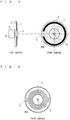
- FIG. 1 shows front and side views of a phosphor wheel unit provided in a light source apparatus of a projector according to a first preferred embodiment of the present invention.
- the phosphor wheel unit includes a phosphor wheel 2, a wheel motor 4 (a rotation driver) that rotatively drives the phosphor wheel 2, and a rotary drive shaft 5 for coupling the phosphor wheel 2 to the wheel motor 4.
- the phosphor wheel 2 has a disk-shaped metallic base material.
- the metallic base material has a phosphor 1 disposed in an annular shape.
- the phosphor 1 has a property for emitting fluorescent light in a green wavelength bandwidth when the metallic base material is irradiated with excitation light in a blue wavelength bandwidth.
- the phosphor wheel 2 has the phosphor 1 disposed in the annular shape.
- the phosphor 1 serves to emit the fluorescent light from the excitation light to the disk-shaped base material to obtain a light source having a predetermined color.
- a diffuse reflection surface 200 for diffusing and reflecting (diffuse reflecting) light is provided on a surface of the metallic base material provided with the phosphor 1 in the phosphor wheel 2.
- the diffuse reflection surface 200 may have a light diffusion property by physically roughening the surface of the metallic base material through a method such as sand blast to provide a very small projection and recess structure, and may have a roughened surface such as a ground glass which is formed by a chemical treatment.
- another thin film having a diffusion property may be disposed in superposition on the metallic base material.
- the phosphor 1 annularly applies a phosphor material onto the reflection surface of the disk-shaped metallic base material by using a dispenser or the like and provides a clearance in such a manner that an application start part and an application end part for the phosphor material do not overlap with each other.
- the phosphor 1 disposed in the annular shape has a discontinuous portion 3 in a part thereof.
- the discontinuous portion 3 can diffuse and reflect incident light.
- the whole disk-shaped metallic base material may be formed by a material for carrying out diffusion and reflection and the phosphor 1 may be provided thereon.
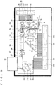
- FIG. 3 shows a plan view of an optical system of the projector according to the first preferred embodiment.
- excitation light 7 having a blue wavelength when excitation light 7 having a blue wavelength is emitted from an excitation light source 6 for emitting excitation light in a blue wavelength bandwidth, the excitation light 7 is reflected by a reflection mirror 8 and passes through condensing lenses 9 and 10 in order, and is reflected by a dichroic mirror 11 for reflecting band light having a blue wavelength and transmitting band light having a green wavelength, and then passes through condensing lenses 12 and 13 in order and the phosphor 1 of the phosphor wheel 2 is irradiated with the excitation light 7.
- the excitation light 7 with which the phosphor 1 is irradiated emits fluorescent light 14 in a green wavelength bandwidth from the phosphor 1.
- the fluorescent light 14 in the green wavelength bandwidth emitted from the phosphor 1 of the phosphor wheel 2 passes through the condensing lenses 13 and 12 in order and is transmitted through the dichroic mirror 11, and is reflected by a dichroic mirror 15 for reflecting band light having a blue wavelength and a green wavelength and transmitting band light having a red wavelength, and then passes through condensing lenses 16 and 17 in order and is incident on a light pipe 18 for converting light emitted from the light source into a luminous flux having uniform intensity distribution.
- blue light 20 emitted from a blue light source 19 passes through a condensing lens 21 and is reflected by the dichroic mirror 11, and then, is further reflected by the dichroic mirror 15 and passes through the condensing lenses 16 and 17 in order, and is incident on the light pipe 18.
- red light 23 emitted from a red light source 22 passes through a condensing lens 24 and is transmitted through the dichroic mirror 15, and then passes through the condensing lenses 16 and 17 in order and is incident on the light pipe 18
- a luminous flux 25 having uniform intensity distribution obtained via the light pipe 18 passes through light guide lenses 26 and 27 in order and is reflected by an irradiation mirror 28, and then passes through a condensing lens 29 so that a image generating element 30 is irradiated with the luminous flux 25.
- projection image light 31 generated by the image generating element 30 passes through a projection lens 32 and is projected onto a screen (not shown) for projecting a image.
- a light source optical system for combining light emitted from each light source is constituted after the light pipe 18 in an optical path.
- Each of the excitation light source 6, the blue light source 19, the red light source 22 and the image generating element 30 includes a cooling radiator. More specifically, the excitation light source 6 has a radiator 33 and is cooled by an air flow generated from a cooling fan 34. Moreover, the blue light source 19 has a radiator 35 and the red light source 22 has a radiator 36, and they are cooled by an air flow generated from a cooling fan 37 respectively. Furthermore, the image generating element 30 has a radiator 38 and is cooled by an air flow generated from a cooling fan 39.
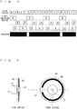
- FIG. 4 shows a timing chart of a light emission period of the light source apparatus according to the first preferred embodiment.
- the projector having the light source apparatus further includes controller (not shown) that controls light emission of the light source, and the controller controls light emission periods for the green excitation light source, the blue light source and the red light source.
- an axis of abscissa indicates a time.
- color display indicates a color to be projected in time division (B represents blue, C represents cyan, R represents red, G represents green and Y represents yellow).
- light emission period indicates light emission periods for a green excitation light source G, a blue light source B and a red light source R.
- Phosphor indicates a period (a black part in the drawing) for which the phosphor 1 disposed in the annular shape on the phosphor wheel 2 is irradiated with the excitation light in the blue wavelength bandwidth to emit fluorescent light in a green wavelength band, and a period of a white part in the drawing indicates a period corresponding to the discontinuous portion 3.
- the control of the light emission periods for the green excitation light source G, the blue light source B and the red light source R is carried out synchronously with a rotation phase of the phosphor wheel 2.
- irradiation with the excitation light 7 is carried out so that fluorescent light is emitted within a range in which the phosphor 1 is coated.
- light is emitted from the blue light source B in the case in which the blue color is projected onto the screen, light is emitted from the blue light source B and the green excitation light source G at the same time in the case in which the cyan is projected, light is emitted from the red light source R in the case in which the red color is projected, light is emitted from the green excitation light source G in the case in which the green color is projected, and light is emitted from the red light source R and the green excitation light source G at the same time in the case in which the yellow color is projected.
- the light emission of the green excitation light source G is controlled by driving the excitation light source 6 in a necessary timing through the controller.
- the excitation light source 6 serves to emit the excitation light with which a passage position of the annular phosphor 1 is irradiated to the phosphor wheel 2 to be rotatively driven by the wheel motor 4. Moreover, the blue light source B and the red light source R emit light having necessary colors for creating combined light to project a image.
- the light emission control is carried out by driving the light sources B and R in a necessary timing through the controller.
- the controller controls the light emission of each light source synchronously with the position of the discontinuous portion 3 with respect to an irradiation position of the excitation light.
- a period corresponding to the discontinuous portion 3 for which the phosphor 1 is not coated is utilized in the light emission of the blue light source B or the red light source R (the light emission of the blue light source B in FIG. 4 ).
- the light emission is controlled by the controller in such a manner that the light emission period for the green excitation light source G is equal to or shorter than a portion other than the period corresponding to the discontinuous portion 3 (that is, a length of the phosphor 1). Accordingly, it is possible to utilize fluorescent light having a stable luminance which is emitted from the phosphor 1 in a portion in which a layer of the coated phosphor 1 has a uniform thickness and width.
- the discontinuous portion 3 is provided in the annular phosphor 1 disposed on the phosphor wheel 2, and the light is emitted from the green excitation light source G synchronously with the rotation phase of the phosphor wheel 2 within the range in which the thickness and the width of the layer of the phosphor 1 are uniform. Therefore, a light quantity of the fluorescent light emitted from the phosphor 1 is stabilized so that the luminance of the green light source is made stable. Accordingly, it is possible to stabilize a brightness of a image to be projected from the projector.
- Such control that the excitation light source G does not emit light is carried out for the period corresponding to the discontinuous portion 3 as described above.
- a synchronization timing is slightly shifted or the light emission of the excitation light source G is continuously carried out in a slight time before the synchronization is actually taken since the start of the control
- the light reflected by the mirror surface returns to the excitation light source G if the discontinuous portion 3 is the mirror surface.
- return light acting as disturbance might cause a laser oscillating operation to be unstable, thereby influencing reliability when the excitation light source G is a semiconductor laser. Therefore, in the first preferred embodiment, there is employed the structure in which the discontinuous portion 3 is set to be a light diffusion surface as described above and many pieces of light are prevented from returning to the semiconductor laser.
- the discontinuous portion 3 of the annular phosphor 1 disposed on the phosphor wheel 2 is provided by forming the clearance in such a manner that the application start part and the application end part do not overlap with each other when the phosphor material is applied annularly by using the dispenser or the like onto the reflection surface of the disk-shaped metallic base material, the present invention is not restricted thereto.
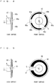
- FIG. 5 shows front and side views of a phosphor wheel unit provided in a light source apparatus of a projector according to a second preferred embodiment of the present invention.
- a discontinuous portion 41 for diffusing and reflecting light is provided in a phosphor 42 disposed on a disk-shaped metallic base material of the phosphor wheel 40.
- the phosphor 42 has the discontinuous portion 41 in a part thereof in the same manner as in the first preferred embodiment.
- the metallic base material has a mirror surface provided on a whole surface thereof, and a portion corresponding to a ground of the phosphor 42 neither diffuses nor reflects the light.
- a region for diffusing and reflecting light is provided in only the discontinuous portion 41 of the phosphor wheel 40. Therefore, it is possible to obtain such an effect as to relieve a risk of causing instability of an operation of a semiconductor laser acting as an excitation light source in the same manner as in the first preferred embodiment. Furthermore, in the case in which there is assumed a procedure for processing a diffusing portion in addition to the metallic base material having the mirror surface provided on the whole surface, it is possible to produce an advantage that the second preferred embodiment can be implemented by a simple and inexpensive method. Moreover, the phosphor wheel 40 needs to keep a dynamic balance in rotation in order to suppress a vibration noise of a wheel motor 4. However, it is also possible to employ an advantageous structure for keeping the dynamic balance by sticking onto the metallic base material a diffusion plate corresponding to a lacking weight of the discontinuous portion of the phosphor 42 as another material.
- FIG. 6 shows front and side views of a phosphor wheel unit provided in a light source apparatus of a projector according to a third preferred embodiment of the present invention.
- green phosphors 43a and 43b are disposed in an annular shape on a disk-shaped metallic base material of the phosphor wheel 44.
- the green phosphors 43a and 43b serve to emit fluorescent light in a green wavelength bandwidth when irradiation with excitation light in a blue wavelength bandwidth is carried out.
- a reflection surface (a mirror surface) for reflecting light is provided on a surface of the metallic base material on which the phosphors 43a and 43b are disposed in the phosphor wheel 44.
- Discontinuous portions 45a and 45b for diffusing and reflecting light are provided between the annular phosphors 43a and 43b.
- the annular phosphors 43a and 43b and the discontinuous portions 45a and 45b are disposed point symmetrically with respect to a center of a rotary shaft (a rotary drive shaft 5) of the phosphor wheel 44, respectively.
- the discontinuous portions 45a and 45b are provided in such a manner that a whole weight balance with respect to the rotary shaft of the phosphor wheel 44 is uniform.
- FIG. 7 shows a timing chart of a light emission period for a light source apparatus according to the third preferred embodiment.
- the projector having the light source apparatus further includes controller (not shown) that controls light emission of a light source, and the controller controls light emission periods for a green excitation light source, a blue light source and a red light source.
- the light emission period for the green excitation light source G corresponds to a range (a black part in the drawing) in which the phosphors 43a and 43b are coated. Moreover, the discontinuous portions 45a and 45b of the phosphor correspond to a white part in the drawing.
- the discontinuous portions 45a and 45b for diffusing and reflecting the light are disposed in two places (a plurality of places) of the phosphor wheel 44 in such a manner that the whole weight balance with respect to the rotary shaft of the phosphor wheel 44 is uniform. For this reason, the rotation of the phosphor wheel 44 is stabilized when the phosphor wheel 44 is rotated at a high speed. Moreover, the rotation of the phosphor wheel 44 is stabilized so that a light quantity of fluorescent light emitted from the phosphors 43a and 43b is made stable and a luminance of a green light source is stabilized. Therefore, it is possible to stabilize a brightness of a image to be projected from the projector. Moreover, light returning to the excitation light source G from the phosphor wheel 44 is almost eliminated. Consequently, it is possible to relieve a risk of causing an operation of a semiconductor laser to be unstable.
- FIG. 8 shows front and side views of a phosphor wheel unit provided in a light source apparatus of a projector according to a fourth preferred embodiment of the present invention.
- green phosphors 46a, 46b and 46c are disposed in an annular shape on a disk-shaped metallic base material of the phosphor wheel 47.
- the green phosphors 46a, 46b and 46c serve to emit fluorescent light in a green wavelength bandwidth when irradiation with excitation light in a blue wavelength bandwidth is carried out.
- Discontinuous portions 48a, 48b and 48c for diffusing and reflecting light are provided between the annular phosphors 46a, 46b and 46c.
- the annular phosphors 46a, 46b and 46c and the discontinuous portions 48a, 48b and 48c are disposed in such a manner that an interval has an angle of 120 degrees with respect to a center of a rotary shaft (a rotary drive shaft 5) of the phosphor wheel 44, respectively.
- the discontinuous portions 48a, 48b and 48c are provided in such a manner that a whole weight balance with respect to the rotary shaft of the phosphor wheel 47 is uniform.
- a reflection surface for reflecting light is provided on the surface of the metallic base material on which the phosphors 46a, 46b and 46c are disposed in the phosphor wheel 47.
- a control timing for a light emission period of each light source is the same as that in the third embodiment ( FIG. 7 ).
- a time on an axis of abscissa in FIG. 7 is varied depending on a rotary speed of the phosphor wheel 47.
- the discontinuous portions 48a, 48b and 48c for diffusing and reflecting the light are disposed in three places (a plurality of places) of the phosphor wheel 47 in such a manner that the whole weight balance with respect to the rotary shaft of the phosphor wheel 47 is uniform. For this reason, the rotation of the phosphor wheel 47 is stabilized when the phosphor wheel 47 is rotated at a high speed. Moreover, the rotation of the phosphor wheel 47 is stabilized so that a light quantity of fluorescent light emitted from the phosphors 46a, 46b and 46c is made stable and a luminance of a green light source is stabilized. Therefore, it is possible to stabilize a brightness of a image to be projected from the projector. Furthermore, light returning to the excitation light source G from the phosphor wheel 47 is almost eliminated. Consequently, it is possible to relieve a risk of causing an operation of a semiconductor laser to be unstable.
- the discontinuous portion to be provided in the annular phosphor of the phosphor wheel may further be disposed in a plurality of places in such a manner that the weight balance with respect to the center of the rotary shaft of the phosphor wheel is kept.
- the rotation of the phosphor wheel is stabilized in the same manner as in the third and fourth preferred embodiments.
- the rotation of the phosphor wheel is stabilized so that a light quantity of the fluorescent light emitted from the phosphor is made stable and the luminance of the light source is stabilized. Consequently, it is possible to stabilize a brightness of a image to be projected from the projector.
- FIG. 9 shows front and side views of a phosphor wheel unit provided in a light source apparatus of a projector according to a fifth preferred embodiment of the present invention.
- a green phosphor 49 is disposed in an annular shape on a disk-shaped metallic base material of the phosphor wheel 50.
- the green phosphor 49 serves to emit fluorescent light in a green wavelength bandwidth when irradiation with excitation light in a blue wavelength bandwidth is carried out.
- a discontinuous portion 51 for diffusing and reflecting light is provided in the annular phosphor 49.
- the phosphor 49 is disposed with a uniform thickness thereof and a variation in a width thereof in such a manner that a whole weight balance with respect to a center of a rotary shaft of the phosphor wheel 50 is uniform. In other words, the width of the phosphor 49 is decreased as a distance to the discontinuous portion 51 increases.
- a minimum width of the phosphor 49 is greater than a spot diameter of excited light subjected to irradiation, and has a sufficient width of the phosphor which does not influence a light quantity of fluorescent light to be emitted.
- the arrangement of the phosphor without an equal width can be executed stably by a method such as screen printing in place of an application device such as a dispenser.
- the discontinuous portion 51 and the phosphor 49 are disposed in the phosphor wheel 50 in such a manner that the whole weight balance with respect to the rotary shaft of the phosphor wheel 50 is uniform. For this reason, the rotation of the phosphor wheel 50 is stabilized when the phosphor wheel 50 is rotated at a high speed. Moreover, the rotation of the phosphor wheel 50 is stabilized so that a light quantity of fluorescent light emitted from the phosphor 49 is made stable and a luminance of a green light source is stabilized. Therefore, it is possible to stabilize a brightness of a image to be projected from the projector. Furthermore, light returning to an excitation light source G from the phosphor wheel 50 is almost eliminated. Consequently, it is possible to relieve a risk of causing an operation of a semiconductor laser to be unstable.
- FIG. 10 shows front and side views of a phosphor wheel unit provided in a light source apparatus of a projector according to a sixth preferred embodiment of the present invention.
- a green phosphor 1 is disposed in an annular shape on a disk-shaped metallic base material of the phosphor wheel 52.
- the green phosphor 1 serves to emit fluorescent light in a green wavelength bandwidth when irradiation with excitation light in a blue wavelength bandwidth is carried out.
- a discontinuous portion 53 for diffusing and reflecting light is provided in the annular phosphor 1.
- the phosphor 1 annularly applies a phosphor material onto the reflection surface of the disk-shaped metallic base material by using a dispenser or the like and provides a clearance (the discontinuous portion 53) in such a manner that an application start part and an application end part for the phosphor material do not overlap with each other.
- the phosphor 1 has an application region 54 provided on an inside of the discontinuous portion 53 (in the vicinity of the discontinuous portion 53).
- a phosphor material is auxiliarily applied to the application region 54.
- the application region 54 is not irradiated with excitation light. Accordingly, the application region 54 does not emit fluorescent light.
- the application region 54 is provided in such a manner that a whole weight balance with respect to a rotary shaft of the phosphor wheel 52 is uniform.
- the auxiliary application region 54 is disposed in such a manner that the whole weight balance with respect to the rotary shaft of the phosphor wheel 52 is uniform. For this reason, the rotation of the phosphor wheel 52 is stabilized when the phosphor wheel 52 is rotated at a high speed. Moreover, the rotation of the phosphor wheel 52 is stabilized so that a light quantity of fluorescent light emitted from the phosphor 1 is made stable and a luminance of a green light source is stabilized. Therefore, it is possible to stabilize a brightness of a image to be projected from the projector. Furthermore, light returning to an excitation light source G from the phosphor wheel 52 is almost eliminated. Consequently, it is possible to relieve a risk of causing an operation of a semiconductor laser to be unstable.
- FIG. 11 shows a plan view of an optical system of a projector according to a seventh preferred embodiment.
- the arrangement of a phosphor wheel unit and a blue light source is changed as compared with the optical system of the projector according to the first preferred embodiment (see FIG. 3 ). Since the other arrangement is the same as that in the first preferred embodiment, description will be omitted.
- excitation light 7 having a blue wavelength which is emitted from an excitation light source 6 for emitting excitation light in a blue wavelength bandwidth is reflected by a reflection mirror 8 and then passes through condensing lenses 9 and 10 in order, and is transmitted through a dichroic mirror 62 for transmitting band light having a blue wavelength and reflecting band light having a green wavelength, and then passes through condensing lenses 12 and 13 and a phosphor 1 of a phosphor wheel 2 is irradiated with the excitation light 7.
- the excitation light 7 subjected to the irradiation is emitted as fluorescent light 14 in a green wavelength bandwidth from the green phosphor 1.
- the fluorescent light 14 in the green wavelength bandwidth emitted from the phosphor 1 of the phosphor wheel 2 passes through the condensing lenses 13 and 12 in order and is reflected by the dichroic mirror 62, and is then reflected by a dichroic mirror 15 for reflecting band light having a blue wavelength and a green wavelength and transmitting band light having a red wavelength, and passes through condensing lenses 16 and 17 in order and is incident on a light pipe 18 for converting light emitted from the light source into a luminous flux 25 having uniform intensity distribution.
- blue light 20 emitted from a blue light source 19 passes through a condensing lens 21 and passes through the dichroic mirror 62, and then, is further reflected by the dichroic mirror 15 and passes through the condensing lenses 16 and 17 in order, and is incident on the light pipe 18.
- red light 23 emitted from a red light source 22 cooled by an air flow generated from a cooling fan 63 passes through a condensing lens 24 and is transmitted through the dichroic mirror 15, and then passes through the condensing lenses 16 and 17 in order and is incident on the light pipe 18.
- the luminous flux 25 having uniform intensity distribution which is obtained by passage through the light pipe 18 passes through light guide lenses 26 and 27 in order, and is reflected by an irradiation mirror 28 and then passes through a condensing lens 29 so that a image generating element 30 is irradiated with the luminous flux 25.
- projection image light 31 generated by the image generating element 30 passes through a projection lens 32 and is then projected onto a screen (not shown) for projecting a image.
- the seventh preferred embodiment it is possible to obtain the same effects as those in the first preferred embodiment even if the arrangement of the phosphor wheel unit and the blue light source is changed as shown in FIG. 11 .
Landscapes
- Physics & Mathematics (AREA)
- Engineering & Computer Science (AREA)
- Multimedia (AREA)
- Signal Processing (AREA)
- General Physics & Mathematics (AREA)
- Optics & Photonics (AREA)
- Spectroscopy & Molecular Physics (AREA)
- General Engineering & Computer Science (AREA)
- Projection Apparatus (AREA)
- Video Image Reproduction Devices For Color Tv Systems (AREA)
- Non-Portable Lighting Devices Or Systems Thereof (AREA)
Description
- The present invention relates to a light source apparatus and a projector including the light source apparatus.
- A light source apparatus provided in a projector according to the related art includes a red light source, a blue light source, an excitation light source for emitting excitation light in a blue wavelength bandwidth, a fluorescent light emitting source having a phosphor wheel to be rotatively driven by a motor, and a light source side optical system. An annular fluorescent light emitting region is provided on a disk-shaped metallic base material in the phosphor wheel of the fluorescent light emitting source. A reflection surface for reflecting light is formed in the fluorescent light emitting region, and a layer of a green phosphor for absorbing the excitation light in the blue wavelength bandwidth to emit fluorescent light in a green wavelength bandwidth is provided on the reflection surface. Both the fluorescent light turned from the layer of the green phosphor toward the reflection surface side and the excitation light turned toward the reflection surface without conversion into the fluorescent light are reflected by the reflection surface. However, the latter (the excitation light) is absorbed into the phosphor again and is thus converted into the fluorescent light. For this reason, many pieces of fluorescent light are emitted as green light from the layer of the green phosphor to the excitation light source side (for example, see Japanese Patent Application Laid-Open No.
2011 - 95388 Page 14,FIG. 4 ). - The phosphor wheel of the light source apparatus disposed in the projector according to the related art is provided with the annular florescent light emitting region. For this reason, a phosphor material is annularly applied by utilizing a dispenser or the like in order to form the layer of the green phosphor on the disk-shaped metallic base material. When the phosphor material is applied annularly, however, an application start portion and an application end portion overlap with each other, and a thickness of the layer of the phosphor in the overlapping portion is different from thicknesses in the other portions. A quantity of the fluorescent light emitted through absorption of the excitation light subjected to irradiation into the phosphor is a sum of a fluorescent light part emitted directly and a fluorescent light part of reemitted light which is reflected by the reflection surface of the phosphor wheel. Therefore, if a difference is made in a thickness and a width of the layer of the phosphor, a total quantity of the fluorescent light is varied. As a result, there is a problem in that a luminance of the light source utilizing the fluorescent light is changed and a brightness of an image to be projected onto a screen is thus influenced (a brightness of the image is changed).
-
US 2011/0075103 A1 discloses a light source controller which is configured to controltimings of driving a first and a second light source and a light source light generator so that the light-source light of two or more colors generated by the light-source light generator and the light-source light emitted from the second light source are cyclically generated, by setting a light-emitting period of at least one light-source light color having a higher luminous efficiency out of the two or more colors generated by the light-source light generator, shorter than those of the other light-source light colors, and setting a drive power of the first light source during generation of the light-source light color whose light-emitting period is set short, greater than a drive power of the first light source during generation of the other light-source light colors. - A further light source apparatus is disclosed in
US2012/0106126A . - In order to solve these problems, it is an object of the present invention to provide a light source apparatus according to claim 1 capable of stabilizing a brightness of a image to be projected onto a screen, and a projector according to claim 6. A light source apparatus includes: a phosphor wheel having a phosphor disposed in an annular shape on a disk-shaped base material, the phosphor serving to emit fluorescent light from excitation light, thereby forming an excitation light source having a predetermined color, and the phosphor having a discontinuous portion for diffusing and reflecting light in a part of the annular shape; a rotation driver that rotatively drives the phosphor wheel; an excitation light source for emitting the excitation light with which a passage position of the circular phosphor is irradiated with respect to the phosphor wheel to be rotatively driven by the rotation driver; a light source having a different color from the predetermined color which is necessary to create combined light for projecting a image; a light source optical system for combining light of the light source and the excitation light source; and a controller that controls light emission of the light source and the excitation light source synchronously with a position of the discontinuous portion with respect to an irradiation position of the excitation light.
- According to the present invention, there are provided a phosphor wheel having a phosphor disposed in an annular shape on a disk-shaped base material, the phosphor serving to emit fluorescent light from excitation light, thereby forming an excitation light source having a predetermined color, and the phosphor having a discontinuous portion for diffusing and reflecting light in a part of the annular shape, a rotation driver that rotatively drives the phosphor wheel, an excitation light source for emitting the excitation light with which a passage position of the circular phosphor is irradiated with respect to the phosphor wheel to be rotatively driven by the rotation driver, a light source having a different color from the predetermined color which is necessary to create combined light for projecting a image, a light source optical system for combining light of the light source and the excitation light source, and a controller that controls light emission of the light source and the excitation light source synchronously with a position of the discontinuous portion with respect to an irradiation position of the excitation light. Therefore, it is possible to stabilize a brightness of a image to be projected onto a screen.
- These and other objects, features, aspects and advantages of the present invention will become more apparent from the following detailed description of the present invention when taken in conjunction with the accompanying drawings.
-
-
FIG. 1 shows front and side views of a phosphor wheel unit according to a first preferred embodiment of the present invention; -
FIG. 2 shows a front view of a disk-shaped metallic base material according to the first preferred embodiment of the present invention; -
FIG. 3 shows a plan view of an optical system of a projector according to the first preferred embodiment of the present invention; -
FIG. 4 shows a timing chart of a light emission period of a light source apparatus according to the first preferred embodiment of the present invention; -
FIG. 5 shows front and side views of a phosphor wheel unit according to a second preferred embodiment of the present invention; -
FIG. 6 shows front and side views of a phosphor wheel unit according to a third preferred embodiment of the present invention; -
FIG. 7 shows a timing chart of a light emission period of a light source apparatus according to the third preferred embodiment of the present invention; -
FIG. 8 shows front and side views of a phosphor wheel unit according to a fourth preferred embodiment of the present invention; -
FIG. 9 shows front and side views of a phosphor wheel unit according to a fifth preferred embodiment of the present invention; -
FIG. 10 shows front and side views of a phosphor wheel unit according to a sixth preferred embodiment of the present invention; and -
FIG. 11 shows a plan view of an optical system of a projector according to a seventh preferred embodiment of the present invention. - Preferred embodiments according to the present invention will be described below with reference to the drawings.
-
FIG. 1 shows front and side views of a phosphor wheel unit provided in a light source apparatus of a projector according to a first preferred embodiment of the present invention. - As shown in
FIG. 1 , the phosphor wheel unit according to the first preferred embodiment includes aphosphor wheel 2, a wheel motor 4 (a rotation driver) that rotatively drives thephosphor wheel 2, and arotary drive shaft 5 for coupling thephosphor wheel 2 to thewheel motor 4. - The
phosphor wheel 2 has a disk-shaped metallic base material. The metallic base material has a phosphor 1 disposed in an annular shape. The phosphor 1 has a property for emitting fluorescent light in a green wavelength bandwidth when the metallic base material is irradiated with excitation light in a blue wavelength bandwidth. In other words, thephosphor wheel 2 has the phosphor 1 disposed in the annular shape. The phosphor 1 serves to emit the fluorescent light from the excitation light to the disk-shaped base material to obtain a light source having a predetermined color. - A
diffuse reflection surface 200 for diffusing and reflecting (diffuse reflecting) light is provided on a surface of the metallic base material provided with the phosphor 1 in thephosphor wheel 2. Thediffuse reflection surface 200 may have a light diffusion property by physically roughening the surface of the metallic base material through a method such as sand blast to provide a very small projection and recess structure, and may have a roughened surface such as a ground glass which is formed by a chemical treatment. Moreover, another thin film having a diffusion property may be disposed in superposition on the metallic base material. - The phosphor 1 annularly applies a phosphor material onto the reflection surface of the disk-shaped metallic base material by using a dispenser or the like and provides a clearance in such a manner that an application start part and an application end part for the phosphor material do not overlap with each other. In other words, the phosphor 1 disposed in the annular shape has a
discontinuous portion 3 in a part thereof. Moreover, thediscontinuous portion 3 can diffuse and reflect incident light. On the other hand, it is desirable that a portion to be a ground of the phosphor 1 should be a mirror surface in which regular reflection is predominant in consideration of a light utilization efficiency.FIG. 2 shows a front view of the disk-shaped metallic base material, and a corresponding portion to a region provided with the phosphor 1 serves as amirror surface 201. In the case in which the light utilization efficiency does not need to have the highest priority, it is not always necessary to provide themirror surface 201. The whole disk-shaped metallic base material may be formed by a material for carrying out diffusion and reflection and the phosphor 1 may be provided thereon. -
FIG. 3 shows a plan view of an optical system of the projector according to the first preferred embodiment. - As shown in
FIG. 3 , whenexcitation light 7 having a blue wavelength is emitted from an excitation light source 6 for emitting excitation light in a blue wavelength bandwidth, theexcitation light 7 is reflected by areflection mirror 8 and passes through condensinglenses dichroic mirror 11 for reflecting band light having a blue wavelength and transmitting band light having a green wavelength, and then passes through condensinglenses phosphor wheel 2 is irradiated with theexcitation light 7. Theexcitation light 7 with which the phosphor 1 is irradiated emitsfluorescent light 14 in a green wavelength bandwidth from the phosphor 1. - The
fluorescent light 14 in the green wavelength bandwidth emitted from the phosphor 1 of thephosphor wheel 2 passes through thecondensing lenses dichroic mirror 11, and is reflected by adichroic mirror 15 for reflecting band light having a blue wavelength and a green wavelength and transmitting band light having a red wavelength, and then passes through condensinglenses light pipe 18 for converting light emitted from the light source into a luminous flux having uniform intensity distribution. - Moreover,
blue light 20 emitted from ablue light source 19 passes through acondensing lens 21 and is reflected by thedichroic mirror 11, and then, is further reflected by thedichroic mirror 15 and passes through thecondensing lenses light pipe 18. - In addition,
red light 23 emitted from ared light source 22 passes through acondensing lens 24 and is transmitted through thedichroic mirror 15, and then passes through thecondensing lenses light pipe 18 - A
luminous flux 25 having uniform intensity distribution obtained via thelight pipe 18 passes throughlight guide lenses irradiation mirror 28, and then passes through acondensing lens 29 so that aimage generating element 30 is irradiated with theluminous flux 25. After theimage generating element 30 is irradiated with theluminous flux 25,projection image light 31 generated by theimage generating element 30 passes through aprojection lens 32 and is projected onto a screen (not shown) for projecting a image. In other words, a light source optical system for combining light emitted from each light source is constituted after thelight pipe 18 in an optical path. - Each of the excitation light source 6, the
blue light source 19, thered light source 22 and theimage generating element 30 includes a cooling radiator. More specifically, the excitation light source 6 has aradiator 33 and is cooled by an air flow generated from a coolingfan 34. Moreover, the bluelight source 19 has aradiator 35 and thered light source 22 has aradiator 36, and they are cooled by an air flow generated from a coolingfan 37 respectively. Furthermore, theimage generating element 30 has aradiator 38 and is cooled by an air flow generated from a coolingfan 39. -
FIG. 4 shows a timing chart of a light emission period of the light source apparatus according to the first preferred embodiment. The projector having the light source apparatus further includes controller (not shown) that controls light emission of the light source, and the controller controls light emission periods for the green excitation light source, the blue light source and the red light source. - In
FIG. 4 , an axis of abscissa indicates a time. Moreover, "color display" indicates a color to be projected in time division (B represents blue, C represents cyan, R represents red, G represents green and Y represents yellow). Moreover, "light emission period" indicates light emission periods for a green excitation light source G, a blue light source B and a red light source R. "Phosphor" indicates a period (a black part in the drawing) for which the phosphor 1 disposed in the annular shape on thephosphor wheel 2 is irradiated with the excitation light in the blue wavelength bandwidth to emit fluorescent light in a green wavelength band, and a period of a white part in the drawing indicates a period corresponding to thediscontinuous portion 3. - As shown in
FIG. 4 , the control of the light emission periods for the green excitation light source G, the blue light source B and the red light source R is carried out synchronously with a rotation phase of thephosphor wheel 2. For the light emission period of the green excitation light source G, irradiation with theexcitation light 7 is carried out so that fluorescent light is emitted within a range in which the phosphor 1 is coated. Moreover, light is emitted from the blue light source B in the case in which the blue color is projected onto the screen, light is emitted from the blue light source B and the green excitation light source G at the same time in the case in which the cyan is projected, light is emitted from the red light source R in the case in which the red color is projected, light is emitted from the green excitation light source G in the case in which the green color is projected, and light is emitted from the red light source R and the green excitation light source G at the same time in the case in which the yellow color is projected. In other words, the light emission of the green excitation light source G is controlled by driving the excitation light source 6 in a necessary timing through the controller. The excitation light source 6 serves to emit the excitation light with which a passage position of the annular phosphor 1 is irradiated to thephosphor wheel 2 to be rotatively driven by thewheel motor 4. Moreover, the blue light source B and the red light source R emit light having necessary colors for creating combined light to project a image. The light emission control is carried out by driving the light sources B and R in a necessary timing through the controller. - Moreover, the controller controls the light emission of each light source synchronously with the position of the
discontinuous portion 3 with respect to an irradiation position of the excitation light. A period corresponding to thediscontinuous portion 3 for which the phosphor 1 is not coated is utilized in the light emission of the blue light source B or the red light source R (the light emission of the blue light source B inFIG. 4 ). Furthermore, the light emission is controlled by the controller in such a manner that the light emission period for the green excitation light source G is equal to or shorter than a portion other than the period corresponding to the discontinuous portion 3 (that is, a length of the phosphor 1). Accordingly, it is possible to utilize fluorescent light having a stable luminance which is emitted from the phosphor 1 in a portion in which a layer of the coated phosphor 1 has a uniform thickness and width. - As described above, according to the first preferred embodiment, the
discontinuous portion 3 is provided in the annular phosphor 1 disposed on thephosphor wheel 2, and the light is emitted from the green excitation light source G synchronously with the rotation phase of thephosphor wheel 2 within the range in which the thickness and the width of the layer of the phosphor 1 are uniform. Therefore, a light quantity of the fluorescent light emitted from the phosphor 1 is stabilized so that the luminance of the green light source is made stable. Accordingly, it is possible to stabilize a brightness of a image to be projected from the projector. - Such control that the excitation light source G does not emit light is carried out for the period corresponding to the
discontinuous portion 3 as described above. In some cases in which a synchronization timing is slightly shifted or the light emission of the excitation light source G is continuously carried out in a slight time before the synchronization is actually taken since the start of the control, the light reflected by the mirror surface returns to the excitation light source G if thediscontinuous portion 3 is the mirror surface. It is known that return light acting as disturbance might cause a laser oscillating operation to be unstable, thereby influencing reliability when the excitation light source G is a semiconductor laser. Therefore, in the first preferred embodiment, there is employed the structure in which thediscontinuous portion 3 is set to be a light diffusion surface as described above and many pieces of light are prevented from returning to the semiconductor laser. - Although the description has been given to the first preferred embodiment in which the
discontinuous portion 3 of the annular phosphor 1 disposed on thephosphor wheel 2 is provided by forming the clearance in such a manner that the application start part and the application end part do not overlap with each other when the phosphor material is applied annularly by using the dispenser or the like onto the reflection surface of the disk-shaped metallic base material, the present invention is not restricted thereto. For example, it is also possible to produce the same effects as those in the preferred embodiment also in the case in which the phosphor material is once applied annularly to the whole periphery of the reflection surface of the disk-shaped metallic base material and a film for reflecting or absorbing excitation light is then stuck onto the corresponding portion to thediscontinuous portion 3 or a material for reflecting or absorbing the excitation light is applied. -
FIG. 5 shows front and side views of a phosphor wheel unit provided in a light source apparatus of a projector according to a second preferred embodiment of the present invention. - As shown in
FIG. 5 , in aphosphor wheel 40 according to the second preferred embodiment, adiscontinuous portion 41 for diffusing and reflecting light is provided in aphosphor 42 disposed on a disk-shaped metallic base material of thephosphor wheel 40. Moreover, thephosphor 42 has thediscontinuous portion 41 in a part thereof in the same manner as in the first preferred embodiment. However, the metallic base material has a mirror surface provided on a whole surface thereof, and a portion corresponding to a ground of thephosphor 42 neither diffuses nor reflects the light. - Since the other structures and operations (a control timing for a light emission period of each light source) is the same as in the first preferred embodiment, description will be omitted.
- As described above, according to the second preferred embodiment, a region for diffusing and reflecting light is provided in only the
discontinuous portion 41 of thephosphor wheel 40. Therefore, it is possible to obtain such an effect as to relieve a risk of causing instability of an operation of a semiconductor laser acting as an excitation light source in the same manner as in the first preferred embodiment. Furthermore, in the case in which there is assumed a procedure for processing a diffusing portion in addition to the metallic base material having the mirror surface provided on the whole surface, it is possible to produce an advantage that the second preferred embodiment can be implemented by a simple and inexpensive method. Moreover, thephosphor wheel 40 needs to keep a dynamic balance in rotation in order to suppress a vibration noise of awheel motor 4. However, it is also possible to employ an advantageous structure for keeping the dynamic balance by sticking onto the metallic base material a diffusion plate corresponding to a lacking weight of the discontinuous portion of thephosphor 42 as another material. -
FIG. 6 shows front and side views of a phosphor wheel unit provided in a light source apparatus of a projector according to a third preferred embodiment of the present invention. - As shown in
FIG. 6 , in aphosphor wheel 44 according to the third preferred embodiment,green phosphors phosphor wheel 44. Thegreen phosphors phosphors phosphor wheel 44. -
Discontinuous portions annular phosphors - The
annular phosphors discontinuous portions phosphor wheel 44, respectively. In other words, thediscontinuous portions phosphor wheel 44 is uniform. - Since the other structures are the same as those in the second preferred embodiment, description will be omitted.
-
FIG. 7 shows a timing chart of a light emission period for a light source apparatus according to the third preferred embodiment. The projector having the light source apparatus further includes controller (not shown) that controls light emission of a light source, and the controller controls light emission periods for a green excitation light source, a blue light source and a red light source. - In
FIG. 7 , the light emission period for the green excitation light source G corresponds to a range (a black part in the drawing) in which thephosphors discontinuous portions - As described above, according to the third preferred embodiment, the
discontinuous portions phosphor wheel 44 in such a manner that the whole weight balance with respect to the rotary shaft of thephosphor wheel 44 is uniform. For this reason, the rotation of thephosphor wheel 44 is stabilized when thephosphor wheel 44 is rotated at a high speed. Moreover, the rotation of thephosphor wheel 44 is stabilized so that a light quantity of fluorescent light emitted from thephosphors phosphor wheel 44 is almost eliminated. Consequently, it is possible to relieve a risk of causing an operation of a semiconductor laser to be unstable. -
FIG. 8 shows front and side views of a phosphor wheel unit provided in a light source apparatus of a projector according to a fourth preferred embodiment of the present invention. - As shown in
FIG. 8 , in aphosphor wheel 47 according to the fourth preferred embodiment,green phosphors phosphor wheel 47. Thegreen phosphors -
Discontinuous portions annular phosphors - The
annular phosphors discontinuous portions phosphor wheel 44, respectively. In other words, thediscontinuous portions phosphor wheel 47 is uniform. - A reflection surface for reflecting light is provided on the surface of the metallic base material on which the
phosphors phosphor wheel 47. - Since the other structures are the same as those in the third preferred embodiment, description will be omitted. Moreover, a control timing for a light emission period of each light source is the same as that in the third embodiment (
FIG. 7 ). A time on an axis of abscissa inFIG. 7 is varied depending on a rotary speed of thephosphor wheel 47. - As described above, according to the fourth preferred embodiment, the
discontinuous portions phosphor wheel 47 in such a manner that the whole weight balance with respect to the rotary shaft of thephosphor wheel 47 is uniform. For this reason, the rotation of thephosphor wheel 47 is stabilized when thephosphor wheel 47 is rotated at a high speed. Moreover, the rotation of thephosphor wheel 47 is stabilized so that a light quantity of fluorescent light emitted from thephosphors phosphor wheel 47 is almost eliminated. Consequently, it is possible to relieve a risk of causing an operation of a semiconductor laser to be unstable. - The discontinuous portion to be provided in the annular phosphor of the phosphor wheel may further be disposed in a plurality of places in such a manner that the weight balance with respect to the center of the rotary shaft of the phosphor wheel is kept. In this case, when the phosphor wheel is rotated at a high speed, the rotation of the phosphor wheel is stabilized in the same manner as in the third and fourth preferred embodiments. Moreover, the rotation of the phosphor wheel is stabilized so that a light quantity of the fluorescent light emitted from the phosphor is made stable and the luminance of the light source is stabilized. Consequently, it is possible to stabilize a brightness of a image to be projected from the projector.
-
FIG. 9 shows front and side views of a phosphor wheel unit provided in a light source apparatus of a projector according to a fifth preferred embodiment of the present invention. - As shown in
FIG. 9 , in aphosphor wheel 50 according to the fifth preferred embodiment, agreen phosphor 49 is disposed in an annular shape on a disk-shaped metallic base material of thephosphor wheel 50. Thegreen phosphor 49 serves to emit fluorescent light in a green wavelength bandwidth when irradiation with excitation light in a blue wavelength bandwidth is carried out. - A
discontinuous portion 51 for diffusing and reflecting light is provided in theannular phosphor 49. - The
phosphor 49 is disposed with a uniform thickness thereof and a variation in a width thereof in such a manner that a whole weight balance with respect to a center of a rotary shaft of thephosphor wheel 50 is uniform. In other words, the width of thephosphor 49 is decreased as a distance to thediscontinuous portion 51 increases. A minimum width of thephosphor 49 is greater than a spot diameter of excited light subjected to irradiation, and has a sufficient width of the phosphor which does not influence a light quantity of fluorescent light to be emitted. The arrangement of the phosphor without an equal width can be executed stably by a method such as screen printing in place of an application device such as a dispenser. - Since the other structures and operations (a control timing for a light emission period of each light source) is the same as in the first preferred embodiment, description will be omitted.
- As described above, according to the fifth preferred embodiment, the
discontinuous portion 51 and thephosphor 49 are disposed in thephosphor wheel 50 in such a manner that the whole weight balance with respect to the rotary shaft of thephosphor wheel 50 is uniform. For this reason, the rotation of thephosphor wheel 50 is stabilized when thephosphor wheel 50 is rotated at a high speed. Moreover, the rotation of thephosphor wheel 50 is stabilized so that a light quantity of fluorescent light emitted from thephosphor 49 is made stable and a luminance of a green light source is stabilized. Therefore, it is possible to stabilize a brightness of a image to be projected from the projector. Furthermore, light returning to an excitation light source G from thephosphor wheel 50 is almost eliminated. Consequently, it is possible to relieve a risk of causing an operation of a semiconductor laser to be unstable. -
FIG. 10 shows front and side views of a phosphor wheel unit provided in a light source apparatus of a projector according to a sixth preferred embodiment of the present invention. - As shown in
FIG. 10 , in aphosphor wheel 52 according to the sixth preferred embodiment, a green phosphor 1 is disposed in an annular shape on a disk-shaped metallic base material of thephosphor wheel 52. The green phosphor 1 serves to emit fluorescent light in a green wavelength bandwidth when irradiation with excitation light in a blue wavelength bandwidth is carried out. - A
discontinuous portion 53 for diffusing and reflecting light is provided in the annular phosphor 1. - The phosphor 1 annularly applies a phosphor material onto the reflection surface of the disk-shaped metallic base material by using a dispenser or the like and provides a clearance (the discontinuous portion 53) in such a manner that an application start part and an application end part for the phosphor material do not overlap with each other.
- Moreover, the phosphor 1 has an
application region 54 provided on an inside of the discontinuous portion 53 (in the vicinity of the discontinuous portion 53). A phosphor material is auxiliarily applied to theapplication region 54. Differently from the phosphor 1 having thediscontinuous portion 53, theapplication region 54 is not irradiated with excitation light. Accordingly, theapplication region 54 does not emit fluorescent light. Moreover, theapplication region 54 is provided in such a manner that a whole weight balance with respect to a rotary shaft of thephosphor wheel 52 is uniform. - Since the other structures and operations (a control timing for a light emission period of each light source) are the same as those in the first preferred embodiment, description will be omitted.
- As described above, according to the sixth preferred embodiment, the
auxiliary application region 54 is disposed in such a manner that the whole weight balance with respect to the rotary shaft of thephosphor wheel 52 is uniform. For this reason, the rotation of thephosphor wheel 52 is stabilized when thephosphor wheel 52 is rotated at a high speed. Moreover, the rotation of thephosphor wheel 52 is stabilized so that a light quantity of fluorescent light emitted from the phosphor 1 is made stable and a luminance of a green light source is stabilized. Therefore, it is possible to stabilize a brightness of a image to be projected from the projector. Furthermore, light returning to an excitation light source G from thephosphor wheel 52 is almost eliminated. Consequently, it is possible to relieve a risk of causing an operation of a semiconductor laser to be unstable. -
FIG. 11 shows a plan view of an optical system of a projector according to a seventh preferred embodiment. - In the optical system of the projector according to the seventh preferred embodiment, the arrangement of a phosphor wheel unit and a blue light source is changed as compared with the optical system of the projector according to the first preferred embodiment (see
FIG. 3 ). Since the other arrangement is the same as that in the first preferred embodiment, description will be omitted. - As shown in
FIG. 11 ,excitation light 7 having a blue wavelength which is emitted from an excitation light source 6 for emitting excitation light in a blue wavelength bandwidth is reflected by areflection mirror 8 and then passes through condensinglenses dichroic mirror 62 for transmitting band light having a blue wavelength and reflecting band light having a green wavelength, and then passes through condensinglenses phosphor wheel 2 is irradiated with theexcitation light 7. Theexcitation light 7 subjected to the irradiation is emitted as fluorescent light 14 in a green wavelength bandwidth from the green phosphor 1. - The
fluorescent light 14 in the green wavelength bandwidth emitted from the phosphor 1 of thephosphor wheel 2 passes through the condensinglenses dichroic mirror 62, and is then reflected by adichroic mirror 15 for reflecting band light having a blue wavelength and a green wavelength and transmitting band light having a red wavelength, and passes through condensinglenses light pipe 18 for converting light emitted from the light source into aluminous flux 25 having uniform intensity distribution. - Moreover,
blue light 20 emitted from a bluelight source 19 passes through a condensinglens 21 and passes through thedichroic mirror 62, and then, is further reflected by thedichroic mirror 15 and passes through the condensinglenses light pipe 18. - Moreover,
red light 23 emitted from ared light source 22 cooled by an air flow generated from a coolingfan 63 passes through a condensinglens 24 and is transmitted through thedichroic mirror 15, and then passes through the condensinglenses light pipe 18. - The
luminous flux 25 having uniform intensity distribution which is obtained by passage through thelight pipe 18 passes throughlight guide lenses irradiation mirror 28 and then passes through a condensinglens 29 so that aimage generating element 30 is irradiated with theluminous flux 25. After theimage generating element 30 is irradiated with theluminous flux 25, projection image light 31 generated by theimage generating element 30 passes through aprojection lens 32 and is then projected onto a screen (not shown) for projecting a image. - As described above, according to the seventh preferred embodiment, it is possible to obtain the same effects as those in the first preferred embodiment even if the arrangement of the phosphor wheel unit and the blue light source is changed as shown in
FIG. 11 . - While the invention has been shown and described in detail, the foregoing description is in all aspects illustrative and not restrictive. It is therefore understood that numerous modifications and variations can be devised without departing from the scope of the invention.
Claims (6)
- A light source apparatus comprising:a phosphor wheel (2) having a phosphor (1) disposed in an annular shape on a disk-shaped base material, the phosphor (1) serving to emit fluorescent light (14) with a predetermined color from excitation light (7), a rotation driver (4) that is arranged to rotatively drive said phosphor wheel (2);an excitation light source (6) for emitting said excitation light (7) with which a passage position of said annular phosphor (1) is irradiated with respect to said phosphor wheel (2) to be rotatively driven by said rotation driver (4);characterized in that said phosphor (1) has a discontinuous portion (3) for diffusing and reflecting Z excitation light (7) in a part of said annular shape; andsaid light source apparatus additionally includes a light source (19,22) for emitting light (20, 23) having a different color from said predetermined color which is necessary to create combined light for projecting an image;a light source optical system (15, 18) for combining light (20, 23) of said light source (19,22) and fluorescent light (14) from excitation light (7) of said excitation light source (6); anda controller that is arranged to control light emission of said light source (19,22) and said excitation light source (6) synchronously with a position of said discontinuous portion (3) with respect to an irradiation position of said excitation light.
- The light source apparatus according to claim 1, wherein said controller is arranged to control an irradiation period for said excitation light so as to be equal to or shorter than a period corresponding to a length of said phosphor (1).
- The light source apparatus according to claim 1 or 2, wherein said phosphor (43a, 43b) has a plurality of said discontinuous portions (45a, 45b).
- The light source apparatus according to claim 1 or 2, wherein said phosphor wheel (52) includes a region (54) to which said phosphor is applied on an inside of said discontinuous portion (53).
- The light source apparatus according to claim 1 or 2, wherein a width of said phosphor (49) is decreased as a distance to said discontinuous portion (51) increases.
- A projector comprising the light source apparatus according to any of claims 1 to 5.
Applications Claiming Priority (2)
| Application Number | Priority Date | Filing Date | Title |
|---|---|---|---|
| JP2013003081 | 2013-01-11 | ||
| JP2013218794A JP6305009B2 (en) | 2013-01-11 | 2013-10-22 | Light source device and projector |
Publications (2)
| Publication Number | Publication Date |
|---|---|
| EP2755085A1 EP2755085A1 (en) | 2014-07-16 |
| EP2755085B1 true EP2755085B1 (en) | 2018-06-20 |
Family
ID=49955141
Family Applications (1)
| Application Number | Title | Priority Date | Filing Date |
|---|---|---|---|
| EP13198966.7A Not-in-force EP2755085B1 (en) | 2013-01-11 | 2013-12-20 | Light source apparatus and projector |
Country Status (4)
| Country | Link |
|---|---|
| US (1) | US10001261B2 (en) |
| EP (1) | EP2755085B1 (en) |
| JP (1) | JP6305009B2 (en) |
| CN (1) | CN103929630B (en) |
Families Citing this family (20)
| Publication number | Priority date | Publication date | Assignee | Title |
|---|---|---|---|---|
| CN102809881B (en) * | 2011-09-22 | 2015-01-21 | 深圳市绎立锐光科技开发有限公司 | Light source system and applied projection system thereof |
| WO2015129656A1 (en) * | 2014-02-27 | 2015-09-03 | 三菱電機株式会社 | Light source apparatus |
| JP6478091B2 (en) * | 2014-09-08 | 2019-03-06 | カシオ計算機株式会社 | Fluorescent wheel, light source device and projection device |
| JP6547270B2 (en) * | 2014-10-10 | 2019-07-24 | 株式会社リコー | Light source device and image projector having the light source device |
| US10557614B2 (en) * | 2015-02-03 | 2020-02-11 | Nippon Electric Glass Co., Ltd. | Projector light source including wavelength conversion member having porous ceramic substrate |
| JP2016170326A (en) * | 2015-03-13 | 2016-09-23 | 日本電気硝子株式会社 | Fluorescent wheel for projector and light emitting device for projector |
| JP2016173391A (en) * | 2015-03-16 | 2016-09-29 | セイコーエプソン株式会社 | Lighting device and projector |
| US10725364B2 (en) | 2016-08-31 | 2020-07-28 | Nec Display Solutions, Ltd. | Projector and drive control method |
| CN108132576B (en) * | 2016-12-01 | 2021-04-23 | 中强光电股份有限公司 | Light source module, projection device and driving method thereof |
| CN106949439A (en) * | 2017-03-22 | 2017-07-14 | 中国科学院苏州生物医学工程技术研究所 | A kind of light supply apparatus based on fluorescence excitation |
| CN106918544A (en) * | 2017-03-29 | 2017-07-04 | 中国科学院苏州生物医学工程技术研究所 | A kind of flow cytometer showed instrument system based on fluorescence excitation light source |
| JP2019028362A (en) * | 2017-08-02 | 2019-02-21 | セイコーエプソン株式会社 | projector |
| JP6825633B2 (en) * | 2019-01-29 | 2021-02-03 | セイコーエプソン株式会社 | Wavelength converters, luminaires and projectors |
| CN111752079B (en) | 2019-03-28 | 2022-05-06 | 中强光电股份有限公司 | Wavelength conversion device and projector |
| CN111983878B (en) * | 2019-05-22 | 2021-10-29 | 中强光电股份有限公司 | Optical rotating device, illumination system, and projection device |
| JP6885423B2 (en) * | 2019-06-27 | 2021-06-16 | 株式会社リコー | A light source device and an image projection device having this light source device |
| CN110568706A (en) * | 2019-08-22 | 2019-12-13 | 苏州佳世达光电有限公司 | Projector with a light source |
| US20220350159A1 (en) * | 2019-09-16 | 2022-11-03 | Materion Precision Optics (Shanghai) Limited | Reflective Diffuser for Reducing Laser Speckle and Reflective Luminescent Wheel Including Same |
| CN114077136B (en) * | 2020-08-20 | 2024-03-08 | 台达电子工业股份有限公司 | Wavelength conversion element and light source module |
| US11953816B2 (en) | 2021-08-06 | 2024-04-09 | Ricoh Company, Ltd. | Wavelength conversion plate, light source device, and image projection apparatus |
Family Cites Families (17)
| Publication number | Priority date | Publication date | Assignee | Title |
|---|---|---|---|---|
| JP4711021B2 (en) | 2009-06-30 | 2011-06-29 | カシオ計算機株式会社 | Projection device |
| JP5796272B2 (en) * | 2009-09-28 | 2015-10-21 | カシオ計算機株式会社 | Light source device, projection device, and projection method |
| JP5713168B2 (en) | 2009-10-28 | 2015-05-07 | カシオ計算機株式会社 | Light source unit and projector |
| JP4873276B2 (en) | 2009-10-28 | 2012-02-08 | カシオ計算機株式会社 | Light source unit and projector |
| JP5500341B2 (en) | 2009-10-28 | 2014-05-21 | カシオ計算機株式会社 | Light source unit and projector |
| US8556437B2 (en) * | 2009-12-17 | 2013-10-15 | Stanley Electric Co., Ltd. | Semiconductor light source apparatus and lighting unit |
| JP5428079B2 (en) | 2009-12-25 | 2014-02-26 | カシオ計算機株式会社 | Fluorescent light emitting device and projector |
| JP5418839B2 (en) * | 2010-01-27 | 2014-02-19 | カシオ計算機株式会社 | Light source unit and projector |
| JP2012008549A (en) * | 2010-05-27 | 2012-01-12 | Panasonic Corp | Light source device and illuminating device using the same, and image display device |
| JP5534331B2 (en) * | 2010-07-30 | 2014-06-25 | カシオ計算機株式会社 | Light source unit and projector |
| US8733942B2 (en) * | 2010-08-09 | 2014-05-27 | Delta Electronics, Inc. | Illumination system and projector using the same |
| US20120106126A1 (en) | 2010-11-01 | 2012-05-03 | Seiko Epson Corporation | Wavelength conversion element, light source device, and projector |
| JP2012098438A (en) * | 2010-11-01 | 2012-05-24 | Seiko Epson Corp | Wavelength conversion element, light source device, and projector |
| JP5817109B2 (en) * | 2010-12-08 | 2015-11-18 | セイコーエプソン株式会社 | Light source device and projector |
| JP2012181394A (en) * | 2011-03-02 | 2012-09-20 | Casio Comput Co Ltd | Light source device and projector |
| US20140028984A1 (en) * | 2011-04-05 | 2014-01-30 | Akihiro Osaka | Light source apparatus and projection display apparatus |
| JP5737769B2 (en) * | 2011-06-16 | 2015-06-17 | Necディスプレイソリューションズ株式会社 | Phosphor color foil, projection display device incorporating the same, and projection display method |
-
2013
- 2013-10-22 JP JP2013218794A patent/JP6305009B2/en not_active Expired - Fee Related
- 2013-12-17 US US14/109,271 patent/US10001261B2/en not_active Expired - Fee Related
- 2013-12-20 EP EP13198966.7A patent/EP2755085B1/en not_active Not-in-force
-
2014
- 2014-01-10 CN CN201410011504.3A patent/CN103929630B/en not_active Expired - Fee Related
Non-Patent Citations (1)
| Title |
|---|
| None * |
Also Published As
| Publication number | Publication date |
|---|---|
| CN103929630A (en) | 2014-07-16 |
| EP2755085A1 (en) | 2014-07-16 |
| US20140198301A1 (en) | 2014-07-17 |
| CN103929630B (en) | 2017-01-11 |
| JP2014149513A (en) | 2014-08-21 |
| US10001261B2 (en) | 2018-06-19 |
| JP6305009B2 (en) | 2018-04-04 |
Similar Documents
| Publication | Publication Date | Title |
|---|---|---|
| EP2755085B1 (en) | Light source apparatus and projector | |
| US9250506B2 (en) | Illumination light source device and projector provided with the same, and control method of the projector | |
| EP3557322B1 (en) | Light source system and projection device | |
| JP5770433B2 (en) | Light source device and image projection device | |
| JP5724245B2 (en) | Light source device, illumination device, and projection display device | |
| JP2012003923A (en) | Lighting device and image display device | |
| JP2013097229A (en) | Projector | |
| US20140028984A1 (en) | Light source apparatus and projection display apparatus | |
| JP2011191466A (en) | Illumination device and projection type image display device | |
| JP2016105122A (en) | Illuminating device and video display device | |
| JP2013041170A (en) | Light source device and projector | |
| JP5799712B2 (en) | Phosphor wheel, light source device and projector | |
| JP2019159332A (en) | Imaging device, program for controlling device, and imaging method | |
| JP5737769B2 (en) | Phosphor color foil, projection display device incorporating the same, and projection display method | |
| JP2015184407A (en) | Illumination device and image display device | |
| JP2016031402A (en) | Lighting device and projection type video display device | |
| JP6137238B2 (en) | Light source device and image projection device | |
| JP2018013541A (en) | Projection type picture display device | |
| JP2019012263A (en) | Light source device and projection type video display device | |
| JP2017022127A (en) | Light source device and image projection apparatus | |
| JP6388051B2 (en) | Light source device and image projection device | |
| JP6353583B2 (en) | Light source device and image projection device | |
| JP2017161627A (en) | Projector and control method for illumination optical system of projector | |
| JP6680340B2 (en) | Light source device and image projection device | |
| JP5146566B2 (en) | Projection apparatus and projector |
Legal Events
| Date | Code | Title | Description |
|---|---|---|---|
| PUAI | Public reference made under article 153(3) epc to a published international application that has entered the european phase |
Free format text: ORIGINAL CODE: 0009012 |
|
| 17P | Request for examination filed |
Effective date: 20131220 |
|
| AK | Designated contracting states |
Kind code of ref document: A1 Designated state(s): AL AT BE BG CH CY CZ DE DK EE ES FI FR GB GR HR HU IE IS IT LI LT LU LV MC MK MT NL NO PL PT RO RS SE SI SK SM TR |
|
| AX | Request for extension of the european patent |
Extension state: BA ME |
|
| R17P | Request for examination filed (corrected) |
Effective date: 20150116 |
|
| RBV | Designated contracting states (corrected) |
Designated state(s): AL AT BE BG CH CY CZ DE DK EE ES FI FR GB GR HR HU IE IS IT LI LT LU LV MC MK MT NL NO PL PT RO RS SE SI SK SM TR |
|
| RIC1 | Information provided on ipc code assigned before grant |
Ipc: G03B 33/08 20060101ALI20171215BHEP Ipc: G03B 21/20 20060101AFI20171215BHEP Ipc: H04N 9/31 20060101ALI20171215BHEP |
|
| GRAP | Despatch of communication of intention to grant a patent |
Free format text: ORIGINAL CODE: EPIDOSNIGR1 |
|
| INTG | Intention to grant announced |
Effective date: 20180126 |
|
| GRAS | Grant fee paid |
Free format text: ORIGINAL CODE: EPIDOSNIGR3 |
|
| GRAA | (expected) grant |
Free format text: ORIGINAL CODE: 0009210 |
|
| AK | Designated contracting states |
Kind code of ref document: B1 Designated state(s): AL AT BE BG CH CY CZ DE DK EE ES FI FR GB GR HR HU IE IS IT LI LT LU LV MC MK MT NL NO PL PT RO RS SE SI SK SM TR |
|
| REG | Reference to a national code |
Ref country code: GB Ref legal event code: FG4D |
|
| REG | Reference to a national code |
Ref country code: IE Ref legal event code: FG4D |
|
| REG | Reference to a national code |
Ref country code: DE Ref legal event code: R096 Ref document number: 602013039135 Country of ref document: DE |
|
| REG | Reference to a national code |
Ref country code: AT Ref legal event code: REF Ref document number: 1011022 Country of ref document: AT Kind code of ref document: T Effective date: 20180715 |
|
| REG | Reference to a national code |
Ref country code: NL Ref legal event code: MP Effective date: 20180620 |
|
| PG25 | Lapsed in a contracting state [announced via postgrant information from national office to epo] |
Ref country code: SE Free format text: LAPSE BECAUSE OF FAILURE TO SUBMIT A TRANSLATION OF THE DESCRIPTION OR TO PAY THE FEE WITHIN THE PRESCRIBED TIME-LIMIT Effective date: 20180620 Ref country code: NO Free format text: LAPSE BECAUSE OF FAILURE TO SUBMIT A TRANSLATION OF THE DESCRIPTION OR TO PAY THE FEE WITHIN THE PRESCRIBED TIME-LIMIT Effective date: 20180920 Ref country code: FI Free format text: LAPSE BECAUSE OF FAILURE TO SUBMIT A TRANSLATION OF THE DESCRIPTION OR TO PAY THE FEE WITHIN THE PRESCRIBED TIME-LIMIT Effective date: 20180620 Ref country code: LT Free format text: LAPSE BECAUSE OF FAILURE TO SUBMIT A TRANSLATION OF THE DESCRIPTION OR TO PAY THE FEE WITHIN THE PRESCRIBED TIME-LIMIT Effective date: 20180620 Ref country code: BG Free format text: LAPSE BECAUSE OF FAILURE TO SUBMIT A TRANSLATION OF THE DESCRIPTION OR TO PAY THE FEE WITHIN THE PRESCRIBED TIME-LIMIT Effective date: 20180920 |
|
| REG | Reference to a national code |
Ref country code: LT Ref legal event code: MG4D |
|
| PG25 | Lapsed in a contracting state [announced via postgrant information from national office to epo] |
Ref country code: GR Free format text: LAPSE BECAUSE OF FAILURE TO SUBMIT A TRANSLATION OF THE DESCRIPTION OR TO PAY THE FEE WITHIN THE PRESCRIBED TIME-LIMIT Effective date: 20180921 Ref country code: RS Free format text: LAPSE BECAUSE OF FAILURE TO SUBMIT A TRANSLATION OF THE DESCRIPTION OR TO PAY THE FEE WITHIN THE PRESCRIBED TIME-LIMIT Effective date: 20180620 Ref country code: HR Free format text: LAPSE BECAUSE OF FAILURE TO SUBMIT A TRANSLATION OF THE DESCRIPTION OR TO PAY THE FEE WITHIN THE PRESCRIBED TIME-LIMIT Effective date: 20180620 Ref country code: LV Free format text: LAPSE BECAUSE OF FAILURE TO SUBMIT A TRANSLATION OF THE DESCRIPTION OR TO PAY THE FEE WITHIN THE PRESCRIBED TIME-LIMIT Effective date: 20180620 |
|
| REG | Reference to a national code |
Ref country code: AT Ref legal event code: MK05 Ref document number: 1011022 Country of ref document: AT Kind code of ref document: T Effective date: 20180620 |
|
| PG25 | Lapsed in a contracting state [announced via postgrant information from national office to epo] |
Ref country code: NL Free format text: LAPSE BECAUSE OF FAILURE TO SUBMIT A TRANSLATION OF THE DESCRIPTION OR TO PAY THE FEE WITHIN THE PRESCRIBED TIME-LIMIT Effective date: 20180620 |
|
| PG25 | Lapsed in a contracting state [announced via postgrant information from national office to epo] |
Ref country code: CZ Free format text: LAPSE BECAUSE OF FAILURE TO SUBMIT A TRANSLATION OF THE DESCRIPTION OR TO PAY THE FEE WITHIN THE PRESCRIBED TIME-LIMIT Effective date: 20180620 Ref country code: RO Free format text: LAPSE BECAUSE OF FAILURE TO SUBMIT A TRANSLATION OF THE DESCRIPTION OR TO PAY THE FEE WITHIN THE PRESCRIBED TIME-LIMIT Effective date: 20180620 Ref country code: SK Free format text: LAPSE BECAUSE OF FAILURE TO SUBMIT A TRANSLATION OF THE DESCRIPTION OR TO PAY THE FEE WITHIN THE PRESCRIBED TIME-LIMIT Effective date: 20180620 Ref country code: EE Free format text: LAPSE BECAUSE OF FAILURE TO SUBMIT A TRANSLATION OF THE DESCRIPTION OR TO PAY THE FEE WITHIN THE PRESCRIBED TIME-LIMIT Effective date: 20180620 Ref country code: AT Free format text: LAPSE BECAUSE OF FAILURE TO SUBMIT A TRANSLATION OF THE DESCRIPTION OR TO PAY THE FEE WITHIN THE PRESCRIBED TIME-LIMIT Effective date: 20180620 Ref country code: IS Free format text: LAPSE BECAUSE OF FAILURE TO SUBMIT A TRANSLATION OF THE DESCRIPTION OR TO PAY THE FEE WITHIN THE PRESCRIBED TIME-LIMIT Effective date: 20181020 Ref country code: PL Free format text: LAPSE BECAUSE OF FAILURE TO SUBMIT A TRANSLATION OF THE DESCRIPTION OR TO PAY THE FEE WITHIN THE PRESCRIBED TIME-LIMIT Effective date: 20180620 |
|
| PG25 | Lapsed in a contracting state [announced via postgrant information from national office to epo] |
Ref country code: IT Free format text: LAPSE BECAUSE OF FAILURE TO SUBMIT A TRANSLATION OF THE DESCRIPTION OR TO PAY THE FEE WITHIN THE PRESCRIBED TIME-LIMIT Effective date: 20180620 Ref country code: SM Free format text: LAPSE BECAUSE OF FAILURE TO SUBMIT A TRANSLATION OF THE DESCRIPTION OR TO PAY THE FEE WITHIN THE PRESCRIBED TIME-LIMIT Effective date: 20180620 Ref country code: ES Free format text: LAPSE BECAUSE OF FAILURE TO SUBMIT A TRANSLATION OF THE DESCRIPTION OR TO PAY THE FEE WITHIN THE PRESCRIBED TIME-LIMIT Effective date: 20180620 |
|
| REG | Reference to a national code |
Ref country code: DE Ref legal event code: R097 Ref document number: 602013039135 Country of ref document: DE |
|
| PLBE | No opposition filed within time limit |
Free format text: ORIGINAL CODE: 0009261 |
|
| STAA | Information on the status of an ep patent application or granted ep patent |
Free format text: STATUS: NO OPPOSITION FILED WITHIN TIME LIMIT |
|
| 26N | No opposition filed |
Effective date: 20190321 |
|
| PG25 | Lapsed in a contracting state [announced via postgrant information from national office to epo] |
Ref country code: DK Free format text: LAPSE BECAUSE OF FAILURE TO SUBMIT A TRANSLATION OF THE DESCRIPTION OR TO PAY THE FEE WITHIN THE PRESCRIBED TIME-LIMIT Effective date: 20180620 |
|
| REG | Reference to a national code |
Ref country code: CH Ref legal event code: PL |
|
| PG25 | Lapsed in a contracting state [announced via postgrant information from national office to epo] |
Ref country code: LU Free format text: LAPSE BECAUSE OF NON-PAYMENT OF DUE FEES Effective date: 20181220 Ref country code: SI Free format text: LAPSE BECAUSE OF FAILURE TO SUBMIT A TRANSLATION OF THE DESCRIPTION OR TO PAY THE FEE WITHIN THE PRESCRIBED TIME-LIMIT Effective date: 20180620 Ref country code: MC Free format text: LAPSE BECAUSE OF FAILURE TO SUBMIT A TRANSLATION OF THE DESCRIPTION OR TO PAY THE FEE WITHIN THE PRESCRIBED TIME-LIMIT Effective date: 20180620 |
|
| REG | Reference to a national code |
Ref country code: IE Ref legal event code: MM4A |
|
| PG25 | Lapsed in a contracting state [announced via postgrant information from national office to epo] |
Ref country code: IE Free format text: LAPSE BECAUSE OF NON-PAYMENT OF DUE FEES Effective date: 20181220 |
|
| PG25 | Lapsed in a contracting state [announced via postgrant information from national office to epo] |
Ref country code: AL Free format text: LAPSE BECAUSE OF FAILURE TO SUBMIT A TRANSLATION OF THE DESCRIPTION OR TO PAY THE FEE WITHIN THE PRESCRIBED TIME-LIMIT Effective date: 20180620 |
|
| PG25 | Lapsed in a contracting state [announced via postgrant information from national office to epo] |
Ref country code: CH Free format text: LAPSE BECAUSE OF NON-PAYMENT OF DUE FEES Effective date: 20181231 Ref country code: LI Free format text: LAPSE BECAUSE OF NON-PAYMENT OF DUE FEES Effective date: 20181231 |
|
| PG25 | Lapsed in a contracting state [announced via postgrant information from national office to epo] |
Ref country code: MT Free format text: LAPSE BECAUSE OF NON-PAYMENT OF DUE FEES Effective date: 20181220 |
|
| PG25 | Lapsed in a contracting state [announced via postgrant information from national office to epo] |
Ref country code: TR Free format text: LAPSE BECAUSE OF FAILURE TO SUBMIT A TRANSLATION OF THE DESCRIPTION OR TO PAY THE FEE WITHIN THE PRESCRIBED TIME-LIMIT Effective date: 20180620 |
|
| PG25 | Lapsed in a contracting state [announced via postgrant information from national office to epo] |
Ref country code: PT Free format text: LAPSE BECAUSE OF FAILURE TO SUBMIT A TRANSLATION OF THE DESCRIPTION OR TO PAY THE FEE WITHIN THE PRESCRIBED TIME-LIMIT Effective date: 20180620 |
|
| PG25 | Lapsed in a contracting state [announced via postgrant information from national office to epo] |
Ref country code: HU Free format text: LAPSE BECAUSE OF FAILURE TO SUBMIT A TRANSLATION OF THE DESCRIPTION OR TO PAY THE FEE WITHIN THE PRESCRIBED TIME-LIMIT; INVALID AB INITIO Effective date: 20131220 Ref country code: CY Free format text: LAPSE BECAUSE OF FAILURE TO SUBMIT A TRANSLATION OF THE DESCRIPTION OR TO PAY THE FEE WITHIN THE PRESCRIBED TIME-LIMIT Effective date: 20180620 Ref country code: MK Free format text: LAPSE BECAUSE OF NON-PAYMENT OF DUE FEES Effective date: 20180620 |
|
| PGFP | Annual fee paid to national office [announced via postgrant information from national office to epo] |
Ref country code: DE Payment date: 20201208 Year of fee payment: 8 Ref country code: GB Payment date: 20201210 Year of fee payment: 8 Ref country code: FR Payment date: 20201112 Year of fee payment: 8 |
|
| PGFP | Annual fee paid to national office [announced via postgrant information from national office to epo] |
Ref country code: BE Payment date: 20201116 Year of fee payment: 8 |
|
| REG | Reference to a national code |
Ref country code: DE Ref legal event code: R119 Ref document number: 602013039135 Country of ref document: DE |
|
| GBPC | Gb: european patent ceased through non-payment of renewal fee |
Effective date: 20211220 |
|
| REG | Reference to a national code |
Ref country code: BE Ref legal event code: MM Effective date: 20211231 |
|
| PG25 | Lapsed in a contracting state [announced via postgrant information from national office to epo] |
Ref country code: GB Free format text: LAPSE BECAUSE OF NON-PAYMENT OF DUE FEES Effective date: 20211220 Ref country code: DE Free format text: LAPSE BECAUSE OF NON-PAYMENT OF DUE FEES Effective date: 20220701 |
|
| PG25 | Lapsed in a contracting state [announced via postgrant information from national office to epo] |
Ref country code: FR Free format text: LAPSE BECAUSE OF NON-PAYMENT OF DUE FEES Effective date: 20211231 Ref country code: BE Free format text: LAPSE BECAUSE OF NON-PAYMENT OF DUE FEES Effective date: 20211231 |