JP5799712B2 - Phosphor wheel, light source device and projector - Google Patents
Phosphor wheel, light source device and projector Download PDFInfo
- Publication number
- JP5799712B2 JP5799712B2 JP2011212556A JP2011212556A JP5799712B2 JP 5799712 B2 JP5799712 B2 JP 5799712B2 JP 2011212556 A JP2011212556 A JP 2011212556A JP 2011212556 A JP2011212556 A JP 2011212556A JP 5799712 B2 JP5799712 B2 JP 5799712B2
- Authority
- JP
- Japan
- Prior art keywords
- light
- light source
- excitation light
- wheel
- phosphor layer
- Prior art date
- Legal status (The legal status is an assumption and is not a legal conclusion. Google has not performed a legal analysis and makes no representation as to the accuracy of the status listed.)
- Active
Links
Images


Landscapes
- Non-Portable Lighting Devices Or Systems Thereof (AREA)
- Projection Apparatus (AREA)
Description
本発明は、蛍光体ホイール、光源装置及びプロジェクターに関する。 The present invention relates to a phosphor wheel, a light source device, and a projector.
プロジェクターは、光源から発した光をデジタル・マイクロミラー・デバイス等の反射型表示素子又は液晶シャッターアレイパネル等の透過型表示素子に照射し、表示素子によって形成された画像を投影レンズによってスクリーンに投影するものである。従来、高輝度の放電ランプを光源として利用するプロジェクターが主流であった。しかし、近年、発光ダイオード、レーザーダイオード、有機エレクトロルミネッセンス素子等といった発光素子を光源として利用し、必要に応じて光源から発した光の色を変換する蛍光体を利用するプロジェクターの開発が多々なされている。例えば、特開2004−341105号公報(特許文献1)には、発光ダイオード及び蛍光体ホイールを利用したプロジェクターが開示されている。この発光ダイオードは紫外光を発するものであり、発光ダイオードから発した紫外光が、回転する蛍光体ホイールの赤色蛍光体層、緑色蛍光体層及び青色蛍光体層に順次繰り返し照射される。そうすると、赤色蛍光体層、緑色蛍光体層及び青色蛍光体層が順次繰り返し励起されるから、赤色光、緑色光及び青色光が蛍光体ホイールから順次繰り返し出射される。 The projector irradiates light emitted from a light source onto a reflective display element such as a digital micromirror device or a transmissive display element such as a liquid crystal shutter array panel, and projects an image formed by the display element onto a screen by a projection lens. To do. Conventionally, projectors using a high-intensity discharge lamp as a light source have been mainstream. However, in recent years, there have been many developments of projectors that use light emitting elements such as light emitting diodes, laser diodes, and organic electroluminescence elements as light sources, and use phosphors that convert the color of light emitted from the light sources as necessary. Yes. For example, Japanese Patent Application Laid-Open No. 2004-341105 (Patent Document 1) discloses a projector using a light emitting diode and a phosphor wheel. This light emitting diode emits ultraviolet light, and the ultraviolet light emitted from the light emitting diode is sequentially and repeatedly irradiated onto the red phosphor layer, the green phosphor layer, and the blue phosphor layer of the rotating phosphor wheel. Then, since the red phosphor layer, the green phosphor layer, and the blue phosphor layer are sequentially and repeatedly excited, red light, green light, and blue light are sequentially emitted from the phosphor wheel.
紫外光は蛍光体ホイール等の光学部品を劣化させやすいので、可視光を励起光として利用することが提案されている。励起光として利用する可視光が光の三原色のうち何れかであれば、その色の蛍光を発する蛍光体層が不要となる。例えば青色の励起光を利用する場合、蛍光体ホイールは、円弧状の開口が形成されたホイール板と、ホイール板の一方の面に形成された蛍光体層と、を有するものである。蛍光体ホイールの回転中に青色の励起光が蛍光体層に照射されると、蛍光体層から別の色の蛍光が発し、励起光が開口に照射され、青色光と別の色の蛍光を順次生成することができる。 Since ultraviolet light tends to deteriorate optical components such as a phosphor wheel, it has been proposed to use visible light as excitation light. If the visible light used as the excitation light is one of the three primary colors of light, a phosphor layer that emits fluorescence of that color becomes unnecessary. For example, when blue excitation light is used, the phosphor wheel has a wheel plate having an arc-shaped opening and a phosphor layer formed on one surface of the wheel plate. When the phosphor layer is irradiated with blue excitation light while the phosphor wheel is rotating, another color of fluorescence is emitted from the phosphor layer, and the excitation light is irradiated to the opening, causing the blue light and the fluorescence of another color to be emitted. Can be generated sequentially.
ところが、蛍光体ホイールの回転中に開口のエッジが励起光の照射個所を通過する時、開口のエッジによって励起光のケラレが発生する。そのため、この蛍光体ホイールを用いたプロジェクターでは、開口のエッジが励起光の照射個所を通過する時に、表示素子に照射される励起光の光束の面内照度分布が不均一になってしまう。 However, when the edge of the aperture passes through the excitation light irradiation site during rotation of the phosphor wheel, vignetting of the excitation light is generated by the edge of the aperture. Therefore, in the projector using this phosphor wheel, the in-plane illuminance distribution of the luminous flux of the excitation light irradiated on the display element becomes non-uniform when the edge of the opening passes the excitation light irradiation portion.
そこで、本発明が解決しようとする課題は、蛍光体ホイールの開口のエッジ近傍での励起光のケラレを防止することである。 Therefore, a problem to be solved by the present invention is to prevent vignetting of excitation light in the vicinity of the edge of the opening of the phosphor wheel.
以上の課題を解決するために、本発明に係る蛍光体ホイールは、軸の回りに回転させられ、一方の面から他方の面に貫通した開口を有するホイール板と、前記ホイール板の前記一方の面に形成され、励起光が照射されるとその励起光と異なる色の蛍光を発する蛍光体層と、を備え、前記開口には、前記ホイール板の前記一方の面と前記他方の面をつなぐエッジ面が形成され、前記エッジ面が、前記開口のうち前記ホイール板の前記一方の面側が前記他方の面側よりも狭くなるように傾斜している。 In order to solve the above problems, a phosphor wheel according to the present invention is rotated around an axis and has a wheel plate having an opening penetrating from one surface to the other surface, and the one of the wheel plates. And a phosphor layer that emits fluorescence of a color different from that of the excitation light when irradiated with excitation light, and the opening connects the one surface of the wheel plate and the other surface. An edge surface is formed, and the edge surface is inclined so that the one surface side of the wheel plate in the opening is narrower than the other surface side.
本発明に係る光源装置は、上記のような蛍光体ホイールと、前記蛍光ホイールを回転駆動する回転駆動器と、前記ホイール板の前記一方の面側から励起光を照射する光源と、を備える。 The light source device according to the present invention includes the phosphor wheel as described above, a rotation driver that rotationally drives the fluorescent wheel, and a light source that emits excitation light from the one surface side of the wheel plate .
本発明に係るプロジェクターは、上記のような光源装置と、前記光源装置によって出射された光を画素毎に変調することで、画像を形成する表示素子と、前記表示素子によって形成された画像を投影する投影光学系と、を備える。 The projector according to the present invention projects the light source device as described above, a display element that forms an image by modulating light emitted from the light source device for each pixel, and an image formed by the display element. A projection optical system .
本発明によれば、エッジ面が傾斜しているから、励起光がエッジ面によって遮光されず、励起光のケラレを防止することができる。 According to the present invention, since the edge surface is inclined, the excitation light is not blocked by the edge surface, and vignetting of the excitation light can be prevented.
以下に、本発明を実施するための形態について、図面を用いて説明する。但し、以下に述べる実施形態には、本発明を実施するために技術的に好ましい種々の限定が付されているが、本発明の範囲を以下の実施形態及び図示例に限定するものではない。 EMBODIMENT OF THE INVENTION Below, the form for implementing this invention is demonstrated using drawing. However, the embodiments described below are given various technically preferable limitations for carrying out the present invention, but the scope of the present invention is not limited to the following embodiments and illustrated examples.
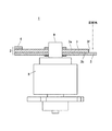
図1は、励起光変換装置1の正面図である。図2は、図1に図示のII−IIに沿った面を矢印方向に見て示した断面図である。図3は、図1に図示のIII−IIIに沿った面を矢印方向に見て示した断面図である。
FIG. 1 is a front view of the excitation
この励起光変換装置1は、所定の色(所定波長帯域)の励起光をそれよりも収束性の低い同色の光に変換することと、その励起光を異なる色(異なる波長帯域)の光に変換することとを交互に行うものである。
This excitation
励起光変換装置1は、蛍光体ホイール2と、この蛍光体ホイール2を回転させるスピンドルモーター8と、を備える。蛍光体ホイール2は、ホイール板3、蛍光体層4及び拡散板5等を有する。
The excitation
ホイール板3は、銅板、アルミニウム板、ステンレス板その他の金属板である。ホイール板3の形状を大づかみに捉えた際のホイール板3の骨格的形状は円板である。ホイール板3の一方の面3aが鏡面研磨加工、銀蒸着加工その他の鏡面加工されており、ホイール板3の一方の面3aに反射面が形成されている。従って、ホイール板3は、反射板である。
The
スピンドルモーター8は回転駆動器である。スピンドルモーター8の駆動軸9がホイール板3に対して直交するようにホイール板3に取り付けられている。具体的には、取付孔3cがホイール板3の中心部を一方の面3aから他方の面3bに貫通し、スピンドルモーター8の駆動軸9が取付孔3cに挿入されて、その駆動軸9がホイール板3に固定されている。以下、軸方向とは、駆動軸9が延びる方向をいい、周方向とは、駆動軸9を中心とした円周方向をいい、径方向とは、駆動軸9に対して直交する方向をいう。
The
ホイール板3はエッジ面3d、エッジ面3e及び開口3fを有する。エッジ面3dは、取付孔3cから径方向外方にずれた位置において径方向に延びており、エッジ面3eは、エッジ面3dから周方向にずれた位置において径方向に延びている。エッジ面3eとエッジ面3dは、駆動軸9を中心とした同一円周上に配置されている。開口3fは、エッジ面3dからエッジ面3eまで周方向に沿って延在しているとともに、これらエッジ面3d,3eの間においてホイール板3の一方の面3aから他方の面3bに貫通している。そして、エッジ面3d,3eは、周方向に沿った開口3fの両端においてホイール板3の一方の面3aと他方の面3bをつなぐ面である。なお、図1では、開口3fの径方向外側が囲まれずに開いているが、開口3fの径方向外側がホイール板3の一部によって囲われ、開口3fが周方向に円弧帯状に延在していてもよい。
The
図3に示すように、エッジ面3dは軸方向に対して傾斜している。具体的には、エッジ面3dは、開口3fのうち一方の面3a側が他方の面3b側よりも狭くなるように、軸方向に対して傾斜している。エッジ面3eも、開口3fのうち一方の面3a側が他方の面3b側よりも狭くなるように、軸方向に対して傾斜している。
As shown in FIG. 3, the
ホイール板3の一方の面3aには、蛍光体層4が形成されている。軸方向に見て、蛍光体層4は、エッジ面3eからエッジ面3dまで周方向に延びるように円弧帯状に形成されている。また、軸方向に見て、蛍光体層4と開口3fとは、駆動軸9を中心とした同一円周上に配置されている。蛍光体層4は、透光性バインダー(例えば、セラミックバインダー、樹脂バインダー、シリコーンバインダー)に蛍光体を分散させたものである。なお、蛍光体層4が円弧帯状に形成されているのではなく、蛍光体層4がホイール板3の一方の面3aの全体に形成されていてもよいし、蛍光体層4が駆動軸9を中心とした扇形状に形作られて、ホイール板3の一方の面3aの一部に形成されていてもよい。
A
図2では、ホイール板3の一方の面3aが平坦な面であって、蛍光体層4がその面3aに付着されている。それに対して、ホイール板3の一方の面3aに円弧帯状の凹部が凹設され、その凹部が周方向に延在し、その凹部内に蛍光体層4が埋められていてもよい。なお、凹部が形成されている場合でも、その凹部が鏡面加工されている。
In FIG. 2, one
図1では、蛍光体層4の径方向外方の縁がホイール板3の外周縁に揃っている。それに対して、蛍光体層4がホイール板3の外周縁よりも内側において周方向に延在していてもよい。
In FIG. 1, the radially outer edge of the
所定の色(所定波長帯域)の励起光が蛍光体層4に入射すると、蛍光体層4は励起光によって励起されて、励起光と異なる色の蛍光を発する。励起光の波長帯域は特に限定するものではないが、励起光が単色の可視光であることが好ましい。蛍光体層4から発する蛍光の色は励起光の色と異なるのであれば、その蛍光の波長帯域は特に限定するものではないが、単色の可視光であることが好ましい。具体的には、励起光の色は光の三原色のうち何れかの色であり、蛍光体層4から発する蛍光の色は光の三原色のうち他の色である。例えば、励起光は青色の波長帯域の光であり、蛍光体層4から発する蛍光は緑色の波長帯域の光である。
When excitation light of a predetermined color (predetermined wavelength band) enters the
図1では、蛍光体層4が形成されている周方向の範囲は、開口3fが形成されている周方向の範囲以外の範囲の全体である。それに対して、図4に示すように、蛍光体層4が形成されている周方向の範囲は、開口3fが形成されている周方向の範囲以外の範囲の一部(例えば、半分)であってもよい。開口3fが形成されている周方向の範囲以外の範囲のうち、蛍光体層4が形成されていない範囲には反射防止層6が形成されていることが好ましい。反射防止層6が形成された面は、ホイール板3の一方の面3aである。
In FIG. 1, the circumferential range in which the
また、図5に示すように、蛍光体層4が周方向に二つに分けられ、二つに分けられた蛍光体層4a,4bのうち第一蛍光体層4aの蛍光色と第二蛍光体層4bの蛍光色が異なっていてもよい。軸方向に見て、第一蛍光体層4aと第二蛍光体層4bは、駆動軸9を中心とした同一円周上に配置されているとともに、互いに周方向にずれて配置されている。蛍光体層4a,4bから発する蛍光の色は励起光の色と異なるのであれば、それらの蛍光の波長帯域は特に限定するものではないが、単色の可視光であることが好ましい。具体的には、励起光の色、第一蛍光体層4aから発する蛍光の色、第二蛍光体層4bから発する蛍光の色は、光の三原色であって、互いに異なる。例えば、励起光は青色の波長帯域の光であり、第一蛍光体層4aから発する蛍光は緑色の波長帯域の光であり、第二蛍光体層4bから発する蛍光は赤色の波長帯域の光である。
In addition, as shown in FIG. 5, the
図1〜図5に示すように、ホイール板3の他方の面3bには、拡散板5が取り付けられている。具体的には、拡散板5がホイール板3の他方の面3bに貼着されて、開口3fが拡散板5によって塞がれている。拡散板5は、励起光を拡散透過させるものである。例えば、拡散板5は、無色透明な透光板の内部に微粒子又は細孔が分散したものであるか、又は無色透明な透光板の表面に微小凹凸を形成したものである。従って、拡散板5を透過した励起光の収束性は、拡散板5を透過する前の励起光よりも低い。
As shown in FIGS. 1 to 5, a
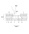
励起光の光軸は駆動軸9から径方向外方にずれているとともに、ホイール板3に対して交差している。励起光の光軸とホイール板3の交点から駆動軸9までの距離は、駆動軸9から蛍光体層4や開口3fまでの距離にほぼ等しい。具体的には、励起光の光軸は、ホイール板3の回転による開口3f及び蛍光体層4の軌跡に直交する。励起光が進行する向きは、ホイール板3の一方の面3aから他方の面3bに向かう向きである。
The optical axis of the excitation light is displaced radially outward from the
ホイール板3の回転中に励起光が開口3fを通過すると、その励起光が拡散板5に入射して、その拡散板5を拡散透過する。そのため、励起光が、拡散板5によって、励起光よりも収束性・指向性の低い透過光に変換される。その透過光の光軸(透過光の光軸とは、光度が最大となる向きに拡散板5から延びる仮想的な線である。)は、励起光の光軸を延長させたものとなる。勿論、透過光の色と励起光の色は同じである。
When the excitation light passes through the
ホイール板3の回転中に励起光が蛍光体層4に入射すると、蛍光体層4が励起光によって励起され、励起光と異なる色の蛍光が蛍光体層4から発する。また、励起光の一部が蛍光体層4を透過しても、その励起光がホイール板3の一方の面3aによって反射され、その反射光によって蛍光体層4が励起され、蛍光体層4から蛍光が発する。そのため、励起光が、蛍光体層4によって、励起光と色の異なる蛍光に変換される。蛍光体層4から発する蛍光は収束性・指向性の低い拡散光であるが、その蛍光の光軸(蛍光の光軸とは、光度が最大となる向きに蛍光体層4から延びる仮想的な線である。)はホイール板3に対して垂直であるとともに、励起光の光軸の反対向きある。
When excitation light enters the
ホイール板3の回転中、励起光が常に点灯しているのではなく、励起光が点滅してもよい。具体的には、図1に示すように、蛍光体層4の周方向に沿った一部の範囲(例えば、半分)Aが励起光の光軸を通過する際には、励起光が消灯し、蛍光体層4の残りの範囲や開口3fが励起光の光軸を通過する際には、励起光が点灯している。なお、蛍光体ホイール2が図5に示すような場合には、励起光が常に点灯している。蛍光体ホイール2が図4に示すような場合には、励起光が常に点灯していてもよいし、励起光が点滅(具体的には、反射防止層6が励起光の光軸を通過する際には、励起光が消灯し、蛍光体層4や開口3fが励起光の光軸を通過する際には、励起光が点灯する。)してもよい。
While the
図3に示すように、ホイール板3の回転中にエッジ面3d,3eが励起光の照射個所を通過する際、励起光がエッジ面3d,3eによってケラレ難い。これは、エッジ面3d,3eが傾斜しているためである。特に、励起光の収束点の位置が蛍光体層4又はその近傍に設定されている場合、励起光が蛍光体層4又はその近傍に集光されるから、開口3fを通過する励起光の光束が太くなっても、励起光がエッジ面3d,3eによってケラレ難い。従って、励起光がエッジ面3d,3e近傍で拡散板5を透過する際の透過光と、励起光がエッジ面3d,3e近傍以外で拡散板5を透過する際の透過光が均一な強度になる。
As shown in FIG. 3, when the edge surfaces 3 d and 3 e pass through the excitation light irradiation portion during the rotation of the
続いて、図6及び図7を参照して、励起光変換装置1及び蛍光体ホイール2を具備するプロジェクター100及び光源装置50について説明する。図6は、プロジェクター100の内部構造を示した平面図である。図7は、プロジェクター100の内部に設けられた光源装置50を示した平面図である。以下の説明では、蛍光体ホイール2が図1又は図4に示すものであり、励起光が青色の波長帯域の光であり、蛍光体層4が励起光によって緑色の蛍光を発するものとする。
Next, the
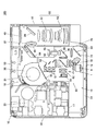
図6に示すように、プロジェクター100は、本体ケース10、制御回路基板20、冷却ファン30、表示素子40、光源装置50、光源側光学系81及び投影光学系90等を備える。
As shown in FIG. 6, the
本体ケース10は、略直方体の箱状に形作られている。つまり、本体ケース10は、正面パネル12、背面パネル13、左右の側面パネル14,15、上面パネル(図示略)及び底面パネル(図示略)等を有する。本体ケース10の内側には、区画用隔壁17が設けられている。本体ケース10の内部空間は、区画用隔壁17によって、背面パネル13側の吸気側の室18と正面パネル12側の排気側の室19とに区画されている。
The
吸気側室18内には制御回路基板20が収容されて、その制御回路基板20が本体ケース10に取り付けられている。制御回路基板20には、電源回路、光源制御回路、画像伸張圧縮回路、画像処理回路、表示駆動回路、冷却ファン制御回路、音声処理回路、モーター駆動回路、各種メモリ及び中央演算処理装置等が搭載されている。
A
冷却ファン30は本体ケース10の内側の略中央部に取り付けられ、冷却ファン30の大部分が吸気側室18内に収容されている。冷却ファン30の吸い込み口31が吸気側の室18側に開口し、冷却ファン30の吐出口32が区画用隔壁17に設けられているとともに、排気側室19側に開口している。冷却ファン30は、吸気側室18から空気を吸引し、吸引した空気を排気側室19へ排出する。冷却ファン30は例えばシロッコファンである。制御回路基板20の冷却ファン制御回路が光源装置50に設けられた温度センサによって検出された温度に基づいて冷却ファン30を制御することによって、冷却ファン30の回転速度やオン・オフのタイミングが制御される。
The cooling
本体ケース10には、吸気側室18から本体ケース10の外に通じた吸気口が設けられているとともに、排気側室19から本体ケース10の外に通じた排気口が設けられている。その排気口の近傍には、排出される空気を冷却する排気温低減装置33が設けられている。
The
排気側室19内には光源装置50が収容されて、その光源装置50が本体ケース10に取り付けられている。光源装置50は、赤色光、緑色光及び青色光を時分割で順次繰り返し出射するものである。
A
図7に示すように、光源装置50は、上述の励起光変換装置1と、青色のレーザー励起光を発する複数の第一光源51と、第一光源51から発する励起光と異なる色の光(赤色光)を発する第二光源61と、第一光源51から発した励起光を集光して励起光変換装置1に照射する第一集光光学系52と、第二光源61から発した赤色光を集光する第二集光光学系62と、励起光変換装置1によって収束性が低下された励起光の光軸、第二集光光学系62によって集光された赤色光の光軸及び励起光変換装置1によって変換された蛍光(緑色光)の光軸を重ねて、これらの励起光、赤色光及び蛍光を出射させる光学系70と、を備える。
As shown in FIG. 7, the
第一光源51は、レーザー励起光を発するレーザーダイオードであって、その光軸が背面パネル13と平行となるように配置されている。これら第一光源51は、二次元アレイ状に配列されている。
The
第一光源51の発光強度は、制御回路基板20の光源制御回路によって調整される。更に、制御回路基板20の光源制御回路は、スピンドルモーター8の回転周期に従って、これら第一光源51を高速で点滅させる。なお、蛍光体ホイール2が図4に示すものである場合、制御回路基板20の光源制御回路が第一光源51を点滅させずに、第一光源51を点灯し続けてもよい。
The light emission intensity of the
第一集光光学系52は、複数のコリメートレンズ53、複数の反射ミラー54及びレンズ群55を有する。コリメートレンズ53が第一光源51にそれぞれ対向配置され、各第一光源51から発したレーザー励起光がコリメートレンズ53によってコリメートされる。反射ミラー54が第一光源51から発したレーザー励起光の光軸に対して斜めになるように第一光源51及びコリメートレンズ53に相対し、コリメートレンズ53によってコリメートされたレーザー励起光の光軸が反射ミラー54によって正面パネル12の方向へ90°変換される。これら反射ミラー54は階段状に配列され、第一光源51から発したレーザー励起光の光軸の間隔がこれら反射ミラー54によって狭められ、これら反射ミラー54によって反射されたレーザー励起光の光束群が占める断面積は、反射ミラー54によって反射される前のレーザー励起光の光束群が占める断面積より狭くなる。レンズ群55は、複数の反射ミラー54によって反射されたレーザー励起光の光束群を集光させて、レーザー励起光の光束群を一つに纏める。
The first condensing
第二光源61は、発光ダイオードであって、その光軸が第一光源51の光軸と平行となるように配置されている。第二光源61の発光強度は、制御回路基板20の光源制御回路によって調整される。更に、制御回路基板20の光源制御回路は、スピンドルモーター8の回転周期に従って、第二光源61を高速で点滅させる。
第二集光光学系62は、第二光源61に対向配置されたレンズ群からなる。第二集光光学系62の光軸と第一集光光学系52のレンズ群55の光軸が直交する。
The second
The second condensing
光学系70は、第一ダイクロイックミラー71、第一反射ミラー72、第二反射ミラー73、第二ダイクロイックミラー74、レンズ群75、第一レンズ76、第二レンズ77、第三レンズ78、第四レンズ79及び第五レンズ80を有する。
The
レンズ群75と第一レンズ76とレンズ群55はこれらの光軸が一直線状になるように配置され、レンズ群55がレンズ群75と第一レンズ76との間に配置されている。
第四レンズ79と第二集光光学系62はこれらの光軸が一直線状になるように配置されている。
The
The fourth lens 79 and the second condensing
第一ダイクロイックミラー71は、レンズ群75とレンズ群55との間であって、且つ、第二集光光学系62とレンズ群55との間に配置されている。第一ダイクロイックミラー71は、レンズ群75及びレンズ群55の光軸に対して45°で斜交するとともに、第二集光光学系62及び第四レンズ79の光軸に対して45°で斜交する。第一ダイクロイックミラー71は、青色及び赤色の波長帯域の光を透過させるとともに、緑色の波長帯域の光を反射させる。
The first
第二レンズ77は、その光軸が第一レンズ76の光軸に直交するように配置されている。
第一反射ミラー72は、第一レンズ76の光軸と第二レンズ77の光軸が交差する位置において、第一レンズ76の光軸に対して45°で斜交するとともに、第二レンズ77の光軸に対して45°で斜交する。
The
The first reflecting
第三レンズ78と第五レンズ80はこれらの光軸が一直線状になるように配置されている。また、第三レンズ78及び第五レンズは、それらの光軸が第二レンズ77の光軸及び第四レンズ79の光軸に対して直交するように配置されている。
第二反射ミラー73は、第二レンズ77の光軸と第三レンズ78の光軸が交差する位置において、第二レンズ77の光軸に対して45°で斜交するとともに、第三レンズ78の光軸に対して45°で斜交する。
第二ダイクロイックミラー74は、第三レンズ78と第五レンズ80との間に配置されている。第二ダイクロイックミラー74は、第三レンズ78の光軸と第四レンズ79の光軸が交差する位置において、第三レンズ78の光軸に対して45°で斜交するとともに、第四レンズ79の光軸に対して45°で斜交する。第二ダイクロイックミラー74は、青色の波長帯域の光を透過させるとともに、赤色及び緑色の波長帯域の光を反射させる。
The
The second reflecting
The second
励起光変換装置1の蛍光体ホイール2は、レンズ群75と第一レンズ76との間に配置されている。具体的には、スピンドルモーター8の駆動軸9がレンズ群75及び第一レンズ76の光軸に対して平行であり、レンズ群75及び第一レンズ76の光軸がホイール板3の開口3fや蛍光体層4を通るようにホイール板3に直交し、ホイール板3の一方の面3aがレンズ群75側に向き、ホイール板3の他方の面3bが第一レンズ76側に向いている。
The
励起光変換装置1のスピンドルモーター8は制御回路基板20のモーター駆動回路によって駆動される。例えば、スピンドルモーター8は等速で回転する。
The
光源装置50の動作について説明する。
スピンドルモーター8が制御回路基板20のモーター駆動回路によって駆動され、ホイール板3が回転する。ホイール板3の回転中に、第一光源51が制御回路基板20の光源制御回路によって点滅させられるとともに、第二光源61が制御回路基板20の光源制御回路によって点滅させられる。具体的には、蛍光体層4の一部(例えば、図1に示すAの範囲)がレンズ群75及び第一レンズ76の光軸を通過している時には、第一光源51が消灯され、第二光源61が点灯される。一方、蛍光体層4の残りの一部(例えば、図1の示すAの範囲以外)や開口3fがレンズ群75及び第一レンズ76の光軸を通過している時には、第一光源51が点灯され、第二光源61が消灯される。
The operation of the
The
第一光源51が消灯し、第二光源61が点灯すると、第二光源61から発した赤色光が第二集光光学系62、第一ダイクロイックミラー71、第四レンズ79を通過する。そして、第四レンズ79を通過した赤色光の光軸が第二ダイクロイックミラー74によって90°変換され、その赤色光が第二ダイクロイックミラー74によって第五レンズ80に向けて反射される。この際、第二光源61から発した赤色光は、第二集光光学系62、第四レンズ79及び第五レンズ80によって光源側光学系81の導光装置82に集光される。
When the
第二光源61が消灯し、第一光源51が点灯すると、第一光源51から発した励起光(青色光)の光軸が反射ミラー54によって90°変換されて、その励起光がレンズ群55に向けて反射される。反射ミラー54によって反射された励起光がレンズ群55、第一ダイクロイックミラー71及びレンズ群75を通過し、蛍光体ホイール2に入射する。この際、第一光源から発した励起光は、反射ミラー54、レンズ群55及びレンズ群75によって蛍光体ホイール2に集光され、励起光の収束点の位置は蛍光体層4又はその近傍の位置になる(図3参照)。その励起光が蛍光体層4に入射すると、蛍光体層4から緑色光(蛍光)が発し、その励起光が拡散板5に入射すると、その励起光が拡散板5を拡散透過する。
When the second
蛍光体層4から発した緑色光はレンズ群75を通過する。レンズ群75を通過した緑色光の光軸が第一ダイクロイックミラー71によって90°変換され、その緑色光が第一ダイクロイックミラー71によって第四レンズ79に向けて反射される。そのため、第一ダイクロイックミラー71によって反射された緑色光の光軸が、第一ダイクロイックミラー71を透過した赤色光の光軸に重なる。第一ダイクロイックミラー71によって反射された緑色光が第四レンズ79を通過する。その緑色光の光軸が第二ダイクロイックミラー74によって90°変換され、その緑色光が第二ダイクロイックミラー74によって第五レンズ80に向けて反射される。この際、蛍光体層4から発した緑色光は、レンズ群75、第四レンズ79及び第五レンズ80によって導光装置82に集光される。
Green light emitted from the
拡散板5を拡散透過した青色光(励起光)は、第一レンズ76を通過する。その青色光の光軸が第一反射ミラー72によって90°変換され、その青色光が第一反射ミラー72によって第二レンズ77に向けて反射される。反射された青色光が第二レンズ77を通過して、第二反射ミラー73によって第三レンズ78に向けて反射される。第二反射ミラー73によって反射された青色光は、第三レンズ78、第二ダイクロイックミラー74及び第五レンズ80を通過する。青色光が第二ダイクロイックミラー74を透過することによって、その青色光の光軸が、第二ダイクロイックミラー74によって反射される赤色光や緑色光の光軸に重なる。この際、拡散板5を拡散透過した青色光は、第一レンズ76、第二レンズ77、第三レンズ78及び第五レンズ80によって導光装置82に集光される。
Blue light (excitation light) diffused and transmitted through the
以上のように、第一光源51と第二光源61が逆相的に点滅し、蛍光体ホイール2が回転することによって、赤色光、緑色光及び青色光が第五レンズ80から時分割で順次繰り返し出射される。
As described above, the
なお、蛍光体ホイール2が図5に示すものである場合、第二光源61及び第二集光光学系62を省略することができる。その場合、第一蛍光体層4aは緑色の蛍光を発するものであり、第二蛍光体層4bは赤色の蛍光を発するものであり、第一ダイクロイックミラー71は青色光を透過させるとともに、赤色光及び緑色光を反射させるものであり、第二ダイクロイックミラー74は赤色光及び緑色光を反射させるとともに、青色光を透過させるものである。更に、第一光源51は点滅せずに、常に点灯している。
In addition, when the
図6を参照して、表示素子40、光源側光学系81及び投影光学系90について詳細に説明する。
表示素子40、光源側光学系81及び投影光学系90は、吸気側の室18のうち側面パネル15寄りに配置されている。
光源側光学系81は、光源装置50から出射された赤色光、緑色光及び青色光を表示素子40に投射するものである。光源側光学系81は、導光装置82、集光レンズ群83、光軸変換ミラー84、集光レンズ群85及び照射ミラー86を有する。
導光装置82及び集光レンズ群83は、これらの光軸が光源装置50の第五レンズ80の光軸と一直線状になるように配置されている。集光レンズ群85は、その光軸が集光レンズ群83の光軸に交差するように配置されている。光軸変換ミラー84は、集光レンズ群83の光軸と集光レンズ群85の光軸が交差する位置において、こられの光軸に対して斜交する。集光レンズ群85は光軸変換ミラー84よりも側面パネル15寄りに配置され、照射ミラー86は集光レンズ群85よりも側面パネル15寄りに配置されている。導光装置82は、ライトトンネル又はライトロッドである。導光装置82は、光源装置50から射出された赤色光、緑色光及び青色光を側面で複数回反射又は全反射させることで、赤色光、緑色光及び青色光を均一な強度分布の光束にする。集光レンズ群83は、導光装置82によって導光された赤色光、緑色光及び青色光を光軸変換ミラー84に向けて投射するとともに、集光する。光軸変換ミラー84は、集光レンズ群83によって投射された赤色光、緑色光及び青色光を集光レンズ群85に向けて反射させる。集光レンズ群85は、光軸変換ミラー84によって反射された赤色光、緑色光及び青色光を照射ミラー86に向けて投射するとともに、集光する。照射ミラー86は、集光レンズ群85によって投射された光を表示素子40に向けて反射させる。
The
The
The light source side
The
表示素子40は、光源側光学系81の照射ミラー86によって照射された赤色光、緑色光及び青色光を画像データに応じて各画素毎(各空間光変調素子毎)に変調することで、画像を形成する反射型空間光変調器である。具体的には、表示素子40は、二次元アレイ状に配列された複数の可動マイクロミラー等を有するデジタル・マイクロミラー・デバイス(DMD)である。
The
表示素子40は制御回路基板20の表示駆動回路によって駆動される。具体的には、赤色光が表示素子40に照射されている際に、表示駆動回路が画像データに従って表示素子40の各可動マイクロミラー毎(各空間光変調素子毎)にPWM制御することで、赤色光が後述の投影光学系90に向けて反射される時間比(ディティー比)が各可動マイクロミラー毎に制御される。これにより、表示素子40によって赤色の画像が形成される。緑色光や青色光が表示素子40に照射されている際も、同様である。
The
なお、表示素子40が反射型の空間光変調器ではなく、透過型の空間光変調器(例えば、液晶シャッターアレイパネル:いわゆる液晶表示器)であってもよい。その場合、光源側光学系81の光学設計を変更し、光源側光学系81によって照射される赤色光、緑色光及び青色光の光軸が後述の投影光学系90の光軸に重なるようにして、投影光学系90と光源側光学系81との間に表示素子40を配置する。
The
投影光学系90は表示素子40に正対するように設けられ、投影光学系90の光軸が前後に延びて表示素子40に交差(具体的には、直交)する。投影光学系90は、表示素子40によって反射された光を前方に投射し、表示素子40によって形成された画像をスクリーンに投影する。この投影光学系90は、可動レンズ群91及び固定レンズ群92等を備えるとともに、ズーム機能及びフォーカス機能を有した可変焦点型レンズである。投影光学系90は、レンズモーター等による可動レンズ群91の移動によって、焦点距離が変更可能であるとともに、フォーカシングが可能である。
The projection
なお、第一光源51は上述のレーザーダイオードではなく、発光ダイオードであってもよい。この場合、蛍光体ホイール2に有する開口3fに配置された拡散板5は設け無くても構わない。
The
以上のプロジェクター100、光源装置50及び蛍光体ホイール2によれば、以下のような作用効果を奏する。
(1) エッジ面3d,3eが傾斜しているから、ホイール板3の回転中にエッジ面3d,3eが励起光の照射個所を通過する際に、励起光のケラレを防止することができる。従って、光源装置50から出射される光が青色光から他の色に切り替わる直前に、表示素子40に照射される青色光の光束の面内照度分布が不均一ならない。そのため、蛍光体ホイール2が一回転している一周期内において形成された青色画像が変化せず、綺麗な画像がスクリーンに投影される。
(2) エッジ面3d,3eが傾斜面であるから、ホイール板3の一方の面3aの面積が小さくならず、蛍光体層4が形成されている周方向の範囲が狭くならない。
According to the
(1) Since the edge surfaces 3d and 3e are inclined, the vignetting of the excitation light can be prevented when the edge surfaces 3d and 3e pass the excitation light irradiation portion while the
(2) Since the edge surfaces 3d and 3e are inclined surfaces, the area of the one
なお、本発明を適用可能な実施形態は、上述した実施形態に限定されることなく、本発明の趣旨を逸脱しない範囲で適宜変更可能である。
第一光源51から発する励起光の色、第二光源61から発する光の色、蛍光体層4から発する蛍光の色は一例であり、別の色であってもよい。例えば、第一光源51から発する励起光の色、第二光源61から発する光の色、蛍光体層4から発する蛍光の色は、光の三原色であって、互いに異なることが好ましい。
同様に、第一光源51から発する励起光の色、第一蛍光体層4aから発する蛍光の色、第二蛍光体層4bから発する色も、別の色であってもよい。例えば、第一光源51から発する励起光の色、第一蛍光体層4aから発する蛍光の色、第二蛍光体層4bから発する色は、光の三原色であって、互いに異なることが好ましい。
The embodiments to which the present invention can be applied are not limited to the above-described embodiments, and can be appropriately changed without departing from the spirit of the present invention.
The color of the excitation light emitted from the
Similarly, the color of the excitation light emitted from the
本発明の実施形態を説明したが、本発明の範囲は、上述の実施の形態に限定するものではなく、特許請求の範囲に記載された発明の範囲とその均等の範囲を含む。
以下に、この出願の願書に最初に添付した特許請求の範囲に記載した発明を付記する。付記に記載した請求項の項番は、この出願の願書に最初に添付した特許請求の範囲の通りである。
〔付記〕
<請求項1>
軸の回りに回転させられ、一方の面から他方の面に貫通した開口を有するホイール板と、
前記ホイール板の前記一方の面に形成され、励起光が照射されるとその励起光と異なる色の蛍光を発する蛍光体層と、
を備え、
周方向に沿った前記開口の両端には、前記ホイール板の前記一方の面と前記他方の面をつなぐエッジ面が形成され、
前記エッジ面が、前記開口のうち前記ホイール板の前記一方の面側が前記他方の面側よりも広くなるように傾斜していることを特徴とする蛍光体ホイール。
<請求項2>
前記開口を塞ぐようにして前記ホイール板の前記他方の面に取り付けられ、前記励起光を透過させる拡散板を備えることを特徴とする請求項1に記載の蛍光体ホイール。
<請求項3>
回転駆動器と、
前記回転駆動器によって軸回りに回転させられ、一方の面から他方の面に貫通した開口を有するホイール板と、
前記ホイール板の前記一方の面に形成され、励起光が照射されるとその励起光と異なる色の蛍光を発する蛍光体層と、
前記ホイール板の回転による前記開口及び前記蛍光体層の軌跡上の所定位置に前記ホイール板の前記一方の面側から励起光を照射する光源と、
前記蛍光体層から発した蛍光の光軸と、前記開口を通過した励起光の光軸とを重ねて、これらの光を出射させる光学系と、
を備え、
周方向に沿った前記開口の両端には、前記ホイール板の前記一方の面と前記他方の面をつなぐエッジ面が形成され、
前記エッジ面が、前記開口のうち前記ホイール板の前記一方の面側が前記他方の面側よりも広くなるように傾斜していることを特徴とする光源装置。
<請求項4>
前記開口を塞ぐようにして前記ホイール板の前記他方の面に取り付けられ、前記励起光を透過させる拡散板を備えることを特徴とする請求項3に記載の光源装置。
<請求項5>
互いに異なる色の光を時分割で順次繰り返し出射する光源装置と、
前記光源装置によって出射された光を各画素毎に変調することで、画像を形成する表示素子と、
前記表示素子によって形成された画像を投影する投影光学系と、
を備え、
前記光源装置が、請求項3又は4に記載されている光源装置であることを特徴とするプロジェクター。
Although the embodiments of the present invention have been described, the scope of the present invention is not limited to the above-described embodiments, and includes the scope of the invention described in the claims and an equivalent scope thereof.
The invention described in the scope of claims attached to the application of this application will be added below. The item numbers of the claims described in the appendix are as set forth in the claims attached to the application of this application.
[Appendix]
<Claim 1>
A wheel plate rotated about an axis and having an opening penetrating from one surface to the other;
A phosphor layer that is formed on the one surface of the wheel plate and emits fluorescence of a color different from the excitation light when irradiated with the excitation light;
With
At both ends of the opening along the circumferential direction, an edge surface connecting the one surface of the wheel plate and the other surface is formed,
The phosphor wheel, wherein the edge surface is inclined so that the one surface side of the wheel plate in the opening is wider than the other surface side.
<Claim 2>
The phosphor wheel according to
<Claim 3>
A rotary drive;
A wheel plate that is rotated about the axis by the rotary driver and has an opening penetrating from one surface to the other surface;
A phosphor layer that is formed on the one surface of the wheel plate and emits fluorescence of a color different from the excitation light when irradiated with the excitation light;
A light source for irradiating excitation light from the one surface side of the wheel plate to a predetermined position on the locus of the opening and the phosphor layer by rotation of the wheel plate;
An optical system for emitting the light by superimposing the optical axis of the fluorescence emitted from the phosphor layer and the optical axis of the excitation light passing through the opening;
With
At both ends of the opening along the circumferential direction, an edge surface connecting the one surface of the wheel plate and the other surface is formed,
The light source device, wherein the edge surface is inclined so that the one surface side of the wheel plate in the opening is wider than the other surface side.
<Claim 4>
The light source device according to
<Claim 5>
A light source device that sequentially and repeatedly emits light of different colors in a time-sharing manner,
A display element that forms an image by modulating light emitted from the light source device for each pixel;
A projection optical system for projecting an image formed by the display element;
With
5. The projector according to
2 蛍光体ホイール
3 ホイール板
3a 一方の面
3b 他方の面
3d エッジ面
3e エッジ面
3f 開口
4 蛍光体層
4a 第一蛍光体層
4b 第二蛍光体層
5 拡散板
8 スピンドルモーター(回転駆動器)
9 駆動軸
40 表示素子
50 光源装置
51 第一光源
61 第二光源
70 光学系
90 投影光学系
100 プロジェクター
2
DESCRIPTION OF
Claims (5)
前記ホイール板の前記一方の面に形成され、励起光が照射されるとその励起光と異なる色の蛍光を発する蛍光体層と、
を備え、
前記開口には、前記ホイール板の前記一方の面と前記他方の面をつなぐエッジ面が形成され、
前記エッジ面が、前記開口のうち前記ホイール板の前記一方の面側が前記他方の面側よりも狭くなるように傾斜していることを特徴とする蛍光体ホイール。 A wheel plate rotated about an axis and having an opening penetrating from one surface to the other;
A phosphor layer that is formed on the one surface of the wheel plate and emits fluorescence of a color different from the excitation light when irradiated with the excitation light;
With
The opening is formed with an edge surface connecting the one surface of the wheel plate and the other surface,
The phosphor wheel, wherein the edge surface is inclined so that the one surface side of the wheel plate in the opening is narrower than the other surface side.
前記蛍光体ホイールを回転駆動する回転駆動器と、
前記ホイール板の前記一方の面側から励起光を照射する光源と、
を備えることを特徴とする光源装置。 The phosphor wheel according to claim 1 or 2,
A rotation driver for rotating the phosphor wheel ;
A light source that emits excitation light from the one surface side of the wheel plate;
A light source device comprising:
前記光源装置によって出射された光を画素毎に変調することで、画像を形成する表示素子と、
前記表示素子によって形成された画像を投影する投影光学系と、
を備えることを特徴とするプロジェクター。 A light source device according to claim 3 or 4 ,
A display element that forms an image by modulating light emitted from the light source device for each pixel;
A projection optical system for projecting an image formed by the display element;
A projector comprising:
Priority Applications (1)
| Application Number | Priority Date | Filing Date | Title |
|---|---|---|---|
| JP2011212556A JP5799712B2 (en) | 2011-09-28 | 2011-09-28 | Phosphor wheel, light source device and projector |
Applications Claiming Priority (1)
| Application Number | Priority Date | Filing Date | Title |
|---|---|---|---|
| JP2011212556A JP5799712B2 (en) | 2011-09-28 | 2011-09-28 | Phosphor wheel, light source device and projector |
Publications (3)
| Publication Number | Publication Date |
|---|---|
| JP2013073063A JP2013073063A (en) | 2013-04-22 |
| JP2013073063A5 JP2013073063A5 (en) | 2014-09-04 |
| JP5799712B2 true JP5799712B2 (en) | 2015-10-28 |
Family
ID=48477603
Family Applications (1)
| Application Number | Title | Priority Date | Filing Date |
|---|---|---|---|
| JP2011212556A Active JP5799712B2 (en) | 2011-09-28 | 2011-09-28 | Phosphor wheel, light source device and projector |
Country Status (1)
| Country | Link |
|---|---|
| JP (1) | JP5799712B2 (en) |
Cited By (1)
| Publication number | Priority date | Publication date | Assignee | Title |
|---|---|---|---|---|
| US11329198B2 (en) | 2018-12-18 | 2022-05-10 | Panasonic Intellectual Property Management Co., Ltd. | Wavelength conversion member, optical device, and projector |
Families Citing this family (6)
| Publication number | Priority date | Publication date | Assignee | Title |
|---|---|---|---|---|
| TWI494604B (en) | 2013-10-31 | 2015-08-01 | 中強光電股份有限公司 | Wavelength conversion and filtering module and light source system |
| JP6432765B2 (en) * | 2014-09-08 | 2018-12-05 | カシオ計算機株式会社 | Light source device and projector |
| WO2016121855A1 (en) * | 2015-01-30 | 2016-08-04 | コニカミノルタ株式会社 | Color wheel for projection-type display device, method for manufacturing same, and projection-type display device including same |
| JP2017167309A (en) * | 2016-03-16 | 2017-09-21 | キヤノン株式会社 | Optical element, light source device, and image projection device |
| CN109254485B (en) | 2017-06-29 | 2021-05-14 | 深圳光峰科技股份有限公司 | Light source device and projection system |
| WO2024043010A1 (en) * | 2022-08-23 | 2024-02-29 | パナソニックIpマネジメント株式会社 | Fluorescent wheel, light source device, projection-type video display device, and method for producing fluorescent wheel |
Family Cites Families (4)
| Publication number | Priority date | Publication date | Assignee | Title |
|---|---|---|---|---|
| TR201809376T4 (en) * | 2006-06-02 | 2018-07-23 | Philips Lighting Holding Bv | Lighting device that produces color and white light. |
| JP5152586B2 (en) * | 2008-09-30 | 2013-02-27 | カシオ計算機株式会社 | Light source device and projector |
| JP5359397B2 (en) * | 2009-03-10 | 2013-12-04 | 株式会社ニコン | Optical member and optical apparatus |
| JP5428079B2 (en) * | 2009-12-25 | 2014-02-26 | カシオ計算機株式会社 | Fluorescent light emitting device and projector |
-
2011
- 2011-09-28 JP JP2011212556A patent/JP5799712B2/en active Active
Cited By (1)
| Publication number | Priority date | Publication date | Assignee | Title |
|---|---|---|---|---|
| US11329198B2 (en) | 2018-12-18 | 2022-05-10 | Panasonic Intellectual Property Management Co., Ltd. | Wavelength conversion member, optical device, and projector |
Also Published As
| Publication number | Publication date |
|---|---|
| JP2013073063A (en) | 2013-04-22 |
Similar Documents
| Publication | Publication Date | Title |
|---|---|---|
| JP6305009B2 (en) | Light source device and projector | |
| JP5799712B2 (en) | Phosphor wheel, light source device and projector | |
| JP5767444B2 (en) | Light source device and image projection device | |
| JP4711154B2 (en) | Light source device and projector | |
| JP5656058B2 (en) | Light emitting unit and projector | |
| JP4697559B2 (en) | Light source device and projector | |
| JP4711156B2 (en) | Light source device and projector | |
| JP5642300B2 (en) | Lighting device | |
| JP5413613B2 (en) | LIGHT SOURCE DEVICE, ITS CONTROL METHOD, AND PROJECTOR | |
| JP2010086815A (en) | Light-emitting device, light source device, and projector using the light source device | |
| JP2011170363A (en) | Light source device and projector | |
| JP5737769B2 (en) | Phosphor color foil, projection display device incorporating the same, and projection display method | |
| JP5783272B2 (en) | Light emitting unit and projector | |
| JP5867536B2 (en) | Light source device and projector | |
| JP5655911B2 (en) | Light source device and projector | |
| JP5445854B2 (en) | Light emitting unit and projector | |
| JP6137238B2 (en) | Light source device and image projection device | |
| JP6417708B2 (en) | Light source device and projector provided with the light source device | |
| JP6439359B2 (en) | Light source device and projector provided with the light source device | |
| JP6286953B2 (en) | Light source device and projection device | |
| JP6819759B2 (en) | Light source device and image projection device | |
| JP2013061675A (en) | Light source device and projector | |
| JP6388051B2 (en) | Light source device and image projection device | |
| JP5348163B2 (en) | Light source device and projector | |
| JP6353583B2 (en) | Light source device and image projection device |
Legal Events
| Date | Code | Title | Description |
|---|---|---|---|
| A521 | Written amendment |
Free format text: JAPANESE INTERMEDIATE CODE: A523 Effective date: 20140717 |
|
| A621 | Written request for application examination |
Free format text: JAPANESE INTERMEDIATE CODE: A621 Effective date: 20140717 |
|
| A977 | Report on retrieval |
Free format text: JAPANESE INTERMEDIATE CODE: A971007 Effective date: 20150514 |
|
| A131 | Notification of reasons for refusal |
Free format text: JAPANESE INTERMEDIATE CODE: A131 Effective date: 20150519 |
|
| A521 | Written amendment |
Free format text: JAPANESE INTERMEDIATE CODE: A523 Effective date: 20150708 |
|
| TRDD | Decision of grant or rejection written | ||
| A01 | Written decision to grant a patent or to grant a registration (utility model) |
Free format text: JAPANESE INTERMEDIATE CODE: A01 Effective date: 20150728 |
|
| A61 | First payment of annual fees (during grant procedure) |
Free format text: JAPANESE INTERMEDIATE CODE: A61 Effective date: 20150810 |
|
| R150 | Certificate of patent or registration of utility model |
Ref document number: 5799712 Country of ref document: JP Free format text: JAPANESE INTERMEDIATE CODE: R150 |