EP2755039B2 - Elektronisches bremsensteuergerät, bremssystem und verfahren zum betrieb desselben - Google Patents
Elektronisches bremsensteuergerät, bremssystem und verfahren zum betrieb desselben Download PDFInfo
- Publication number
- EP2755039B2 EP2755039B2 EP13005583.3A EP13005583A EP2755039B2 EP 2755039 B2 EP2755039 B2 EP 2755039B2 EP 13005583 A EP13005583 A EP 13005583A EP 2755039 B2 EP2755039 B2 EP 2755039B2
- Authority
- EP
- European Patent Office
- Prior art keywords
- data
- vehicle
- speed sensor
- rotational speed
- transmission
- Prior art date
- Legal status (The legal status is an assumption and is not a legal conclusion. Google has not performed a legal analysis and makes no representation as to the accuracy of the status listed.)
- Active
Links
Images
Classifications
-
- B—PERFORMING OPERATIONS; TRANSPORTING
- B60—VEHICLES IN GENERAL
- B60T—VEHICLE BRAKE CONTROL SYSTEMS OR PARTS THEREOF; BRAKE CONTROL SYSTEMS OR PARTS THEREOF, IN GENERAL; ARRANGEMENT OF BRAKING ELEMENTS ON VEHICLES IN GENERAL; PORTABLE DEVICES FOR PREVENTING UNWANTED MOVEMENT OF VEHICLES; VEHICLE MODIFICATIONS TO FACILITATE COOLING OF BRAKES
- B60T8/00—Arrangements for adjusting wheel-braking force to meet varying vehicular or ground-surface conditions, e.g. limiting or varying distribution of braking force
- B60T8/17—Using electrical or electronic regulation means to control braking
- B60T8/172—Determining control parameters used in the regulation, e.g. by calculations involving measured or detected parameters
-
- B—PERFORMING OPERATIONS; TRANSPORTING
- B60—VEHICLES IN GENERAL
- B60T—VEHICLE BRAKE CONTROL SYSTEMS OR PARTS THEREOF; BRAKE CONTROL SYSTEMS OR PARTS THEREOF, IN GENERAL; ARRANGEMENT OF BRAKING ELEMENTS ON VEHICLES IN GENERAL; PORTABLE DEVICES FOR PREVENTING UNWANTED MOVEMENT OF VEHICLES; VEHICLE MODIFICATIONS TO FACILITATE COOLING OF BRAKES
- B60T2250/00—Monitoring, detecting, estimating vehicle conditions
- B60T2250/04—Vehicle reference speed; Vehicle body speed
-
- B—PERFORMING OPERATIONS; TRANSPORTING
- B60—VEHICLES IN GENERAL
- B60T—VEHICLE BRAKE CONTROL SYSTEMS OR PARTS THEREOF; BRAKE CONTROL SYSTEMS OR PARTS THEREOF, IN GENERAL; ARRANGEMENT OF BRAKING ELEMENTS ON VEHICLES IN GENERAL; PORTABLE DEVICES FOR PREVENTING UNWANTED MOVEMENT OF VEHICLES; VEHICLE MODIFICATIONS TO FACILITATE COOLING OF BRAKES
- B60T2260/00—Interaction of vehicle brake system with other systems
- B60T2260/04—Automatic transmission
-
- B—PERFORMING OPERATIONS; TRANSPORTING
- B60—VEHICLES IN GENERAL
- B60T—VEHICLE BRAKE CONTROL SYSTEMS OR PARTS THEREOF; BRAKE CONTROL SYSTEMS OR PARTS THEREOF, IN GENERAL; ARRANGEMENT OF BRAKING ELEMENTS ON VEHICLES IN GENERAL; PORTABLE DEVICES FOR PREVENTING UNWANTED MOVEMENT OF VEHICLES; VEHICLE MODIFICATIONS TO FACILITATE COOLING OF BRAKES
- B60T8/00—Arrangements for adjusting wheel-braking force to meet varying vehicular or ground-surface conditions, e.g. limiting or varying distribution of braking force
- B60T8/32—Arrangements for adjusting wheel-braking force to meet varying vehicular or ground-surface conditions, e.g. limiting or varying distribution of braking force responsive to a speed condition, e.g. acceleration or deceleration
- B60T8/321—Arrangements for adjusting wheel-braking force to meet varying vehicular or ground-surface conditions, e.g. limiting or varying distribution of braking force responsive to a speed condition, e.g. acceleration or deceleration deceleration
- B60T8/329—Systems characterised by their speed sensor arrangements
Definitions
- the invention relates to an electronic braking system according to the preamble of claim 1.
- the invention also relates to a method according to claim 6 and a vehicle according to claim 10.
- Electronic braking systems for vehicles, especially trucks, are typically combined with pneumatic or (rarely) hydraulic braking systems to form electro-pneumatic or electro-hydraulic braking systems.
- Electromechanical braking systems are also possible.
- an electronic brake control unit and at least wheel speed sensors, so that additional functions can be performed beyond the pure braking function, in particular an anti-lock function when braking.
- Electronic brake control unit means any unit, sub-unit or assembly with which data relating to brake functions are processed.
- it can also be an electronic switching unit that is integrated into a so-called axle modulator or that is part of a superordinate electronic switching unit of the vehicle.
- passive sensors are usually used as wheel speed sensors. Passive sensors are less expensive and less sensitive to temperature than active sensors. Sensors that require a supply voltage and preferably contain temperature-sensitive semiconductors are referred to as active sensors.
- a reliable detection of low speeds and the direction of rotation is not possible with the passive wheel speed sensors.
- Active sensors are therefore required for certain functions, for example for detecting a roll from 0 km/h and detecting the direction of rotation.
- the roller detection can be used advantageously for buses at bus stops and generally when stopping on uphill or downhill routes.
- the electronic brake system would therefore have to have more expensive, active speed sensors on the wheels instead of the inexpensive passive speed sensors.
- Certain vehicles equipped with an electronic brake system in particular commercial vehicles, have an automated transmission with an electronic transmission control unit. Transmissions of this type typically have an active speed sensor on a transmission output shaft. The active speed sensor mentioned has so far only been used to control the transmission and is not connected to the electronic braking system.
- the object of the present invention is to create a brake control unit or an electronic brake system with which it is possible to easily determine low speeds and detect the direction of rotation of the wheels, in particular roll detection from 0 km/h and also when the transmission is idling.
- the electronic braking system has the features of claim 1 to solve the problem. Accordingly, the brake control unit processes the data from an active speed sensor on a shaft assigned to an output of the transmission.
- the brake control unit receives the data from the active speed sensor from the latter directly or via another control unit and a data bus/a suitable data interface.
- the active speed sensor is preferably arranged on a transmission output shaft. However, the sensor can also be assigned to a shaft which is firmly connected to the transmission output shaft and is therefore functionally assigned to the output of the transmission.
- the transmission output and the drive wheels of the vehicle are firmly connected to one another, i.e. even when the transmission is idling. This means that as soon as the vehicle starts to roll, the transmission output shaft or a shaft that is permanently connected to it also rotates.
- the active speed sensor provided in the area of the transmission output is suitable for detecting low speeds and recognizing the direction of travel.
- the thermal load on the sensor on the transmission output shaft is also lower or more manageable than with a sensor in the area of the wheel brakes of a commercial vehicle. Additional active speed sensors in the area of the vehicle's wheels can therefore be dispensed with.
- the brake control unit receives the data from the active speed sensor at the transmission output via the vehicle's data bus, only the software of the brake control unit needs to be adapted to process the data from the active speed sensor.
- the brake control unit is typically connected to the vehicle's data bus. Alternatively, a connection for a connection to the active speed sensor at the transmission output can be provided on the brake control unit.
- the brake control unit processes the data from the active speed sensor to determine a vehicle speed from 0 km/h and below a limit speed.
- the brake control unit advantageously processes the data from the active speed sensor to determine a direction of rotation of the shaft and/or a direction of travel of the vehicle.
- the direction of rotation or direction of travel can be important, for example, for the controlled holding of the vehicle when starting off on a non-level road.
- the brake control unit processes the data from the active speed sensor as an input variable for a stop brake and/or for a function for holding the vehicle on an uphill or downhill stretch.
- the stop function and/or the so-called hillholder function can thus be implemented in the brake control unit in a simple manner, namely by adapting the software. In both cases, the service brakes are applied by the brake control unit in order to hold the vehicle.
- the data from this sensor can be transmitted to the electronic brake system.
- the desired functions can be implemented inexpensively and in a simple manner.
- the sensor must be added to vehicles without an active speed sensor on the gearbox output. The additional costs are overcompensated by the fact that intervention in the usual components of the electronic braking system is not required and the more favorable placement of the active speed sensor from a thermal point of view.
- the invention can therefore be used not only for vehicles with an automatic transmission, transmission control device and speed sensor that is provided anyway at the transmission output, but also for other vehicles.
- the active speed sensor is advantageously coupled to the electronic brake control unit directly via a line or indirectly via a control unit with a data interface or a data bus.
- a CAN bus is typically provided as the data bus in motor vehicles. However, another data bus can also be used. Depending on the function to be implemented, the data transmission speed via the data bus is sufficient.
- the active speed sensor has a pole ring with teeth that are finer than the teeth of a gear wheel on the shaft of the transmission that is preferably assigned to the active speed sensor. If the transmission already has an active speed sensor at the transmission output, the sensor typically scans the teeth of a gear wheel. A higher resolution is desirable for certain applications. A pole ring with finer teeth can therefore be provided, in particular on the transmission output shaft.
- an electronic brake control unit processes in particular a value representing the speed of the vehicle. Provision is made for the electronic brake control unit to process data or output values from an active speed sensor, which is present on a shaft associated with an output of the transmission. By processing the data/output values of this sensor, additional functions of the electronic brake system can be implemented without the vehicle having to have active wheel speed sensors. In particular, it is about the detection of low speeds or a roll detection and the detection of the direction of rotation.
- a vehicle according to the invention in particular a commercial vehicle and/or a vehicle with a preferably automatic or automated transmission, has an electronic braking system of the type described.
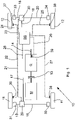
- an electro-pneumatic braking system is provided in a vehicle 10 with two front wheels 11, two rear wheels 12, engine M, transmission G, clutch 13 and transmission output shaft 14 is according to 1 an electro-pneumatic braking system is provided. This is drawn very simplified here, namely without compressed air supply and associated supply lines. Solid lines can be seen as the pneumatic lines carrying the working pressure, namely lines 15, 16, 17, 18, 19 and 20. Data lines 21, 22, 23, 24, 25, 26, 27 and 28 are also provided, which are drawn in dashed lines and through which information and control commands can be exchanged.
- the pneumatic lines 17, 19 and the data line 28 are connected to a brake pedal (not shown) as a brake value transmitter for a service brake.
- a brake pedal (not shown) as a brake value transmitter for a service brake.
- corresponding information is sent via data line 28 to an electronic brake control unit BS.
- a pressure control module 29 for brakes on a front axle and a pressure control module 30 for brakes on a rear axle are controlled via the data lines 22, 24.
- the corresponding working pressure reaches the pressure control modules 29, 30 via the pneumatic lines 17, 19 when the brake pedal is actuated .
- the electro-pneumatic braking system is equipped with an anti-lock function.
- the front wheels 11 and rear wheels 12 are assigned wheel speed sensors 35, 36, 37, 38, namely one wheel speed sensor per wheel.
- the wheel speeds are continuously transmitted to the electronic brake control unit BS via the data lines 21, 23, 25, 27. If necessary, the brake control unit BS adjusts the working pressure for the pressure control modules 29, 30 anew.
- the wheel speed sensors 35 to 38 are designed as passive sensors. These do not detect the direction of rotation of the wheels 11, 12. Speed detection at very low speeds is also not possible. This is harmless for the core function of the anti-lock braking system, namely for non-locking braking from medium and high speeds. For other applications, for example for monitoring a brief standstill or when manoeuvring, the detection of even the smallest speeds and/or the difference between forward and reverse travel can be important.
- an active speed sensor 39 is provided on the transmission output shaft 14 of the transmission G, which is connected to the brake control unit BS via the data line 26 .
- the transmission output shaft 14 is coupled without interruption to the rear wheels 12, so that a rolling of the vehicle 10 and the direction of travel can be detected by the sensor 39 and the corresponding data are available in the brake control unit BS.
- Comfort functions can be implemented via the brake control unit BS using the data from the sensor 39, for example preventing the vehicle from rolling even without deliberate actuation of the accelerator pedal (not shown here) for the motor M.
- the position of the accelerator pedal is available as information in the brake control unit BS . With this function, for example, a bus can be secured against unintentional rolling at bus stops, which is particularly important for vehicles with barrier-free (disabled) access.
- the data lines 21 to 28 can be connected directly to the brake control unit BS, as shown, or they can be connected to the brake control unit BS via a data bus, for example a CAN bus.
- the active speed sensor 39 can scan the teeth of a gear wheel, not shown, on the transmission output shaft 14 .
- An additional pole ring with finer teeth is provided on the transmission output shaft 14 and is scanned by the active speed sensor 39 .
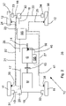
- the transmission G is an automated transmission with transmission control unit GS.
- the clutch 13 is electronically operated.
- the active speed sensor 39 on the transmission output shaft 14 is connected to the transmission control unit GS via a data line 40, not to the brake control unit BS.
- Transmission control unit GS and brake control unit BS are both connected to a CAN bus 41 .
- the data from the active speed sensor 39 are distributed via the transmission control unit GS and the CAN bus 41 and are therefore also available to the brake control unit BS.
Landscapes
- Engineering & Computer Science (AREA)
- Transportation (AREA)
- Mechanical Engineering (AREA)
- Regulating Braking Force (AREA)
- Braking Systems And Boosters (AREA)
Description
- Die Erfindung betrifft ein elektronisches Bremssystem nach dem Oberbegriff des Anspruchs 1. Weiterhin betrifft die Erfindung ein Verfahren gemäß Anspruch 6 und ein Fahrzeug gemäß Anspruch 10.
- Elektronische Bremssysteme für Fahrzeuge, insbesondere Lastkraftwagen, werden typischerweise kombiniert mit pneumatischen oder (seltener) hydraulischen Bremssystemen und bilden so elektro-pneumatische oder elektro-hydraulische Bremssysteme. Möglich sind auch elektromechanische Bremssysteme.
- Spezifische Bestandteile eines elektronischen Bremssystems sind ein elektronisches Bremsensteuergerät und zumindest Raddrehzahlsensoren, so dass über die reine Bremsfunktion hinaus zusätzliche Funktionen ausführbar sind, insbesondere eine Antiblockierfunktion beim Bremsen.
- Einige solcher Beispiele sind in den
DE 198 46 667 A1 sowie in derWO 2006/122623 A1 offenbart. elektronisches Bremsensteuergerät ist jede Einheit, Teileinheit oder Baugruppe zu verstehen, mit der Daten, welche Bremsfunktionen betreffen, verarbeitet werden. Es kann sich beispielsweise auch um eine elektronische Schalteinheit handeln, die in einen sogenannten Achsmodulator integriert ist oder die Teil einer übergeordneten elektronischen Schalteinheit des Fahrzeugs ist. - Als Raddrehzahlsensoren werden üblicherweise sogenannte passive Sensoren verwendet. Passive Sensoren sind kostengünstiger und weniger temperaturempfindlich als aktive Sensoren. Als aktive Sensoren werden solche Sensoren bezeichnet, die eine Versorgungsspannung benötigen und vorzugsweise temperaturempfindliche Halbleiter enthalten.
- Mit den passiven Raddrehzahlsensoren ist eine zuverlässige Erkennung niedriger Geschwindigkeiten und der Drehrichtung nicht möglich. Für bestimmte Funktionen werden demnach aktive Sensoren benötigt, so beispielsweise für eine Rollerkennung ab 0 km/h und eine Erkennung der Drehrichtung. Die Rollerkennung ist vorteilhaft verwendbar für Omnibusse an Haltestellen und generell bei Halt an ansteigenden oder abschüssigen Strecken. Für eine Realisierung dieser Funktionen müsste demnach das elektronische Bremssystem anstelle der kostengünstigen passiven Drehzahlsensoren teurere, aktive Drehzahlsensoren an den Rädern aufweisen.
- Bestimmte, mit einem elektronischen Bremssystem ausgestattete Fahrzeuge, insbesondere Nutzfahrzeuge, weisen ein automatisiertes Getriebe mit elektronischem Getriebesteuergerät auf. Derartige Getriebe verfügen typischerweise über einen aktiven Drehzahlsensor an einer Getriebeausgangswelle. Der genannte aktive Drehzahlsensor wird bislang nur zur Steuerung des Getriebes verwendet und steht nicht in Verbindung mit dem elektronischen Bremssystem.
- Aufgabe der vorliegenden Erfindung ist die Schaffung eines Bremsensteuergerätes bzw. eines elektronischen Bremssystems, mit dem auf einfache Weise eine Bestimmung niedriger Geschwindigkeiten und eine Drehrichtungserkennung der Räder möglich ist, insbesondere eine Rollerkennung ab 0 km/h und auch im Leerlauf des Getriebes.
- Zur Lösung der Aufgabe weist das elektronische Bremssystem die Merkmale des Anspruchs 1 auf. Demnach verarbeitet das Bremsensteuergerät die Daten eines aktiven Drehzahlsensors an einer einem Ausgang des Getriebes zugeordneten Welle. Das Bremsensteuergerät erhält die Daten des aktiven Drehzahlsensors von Letzterem unmittelbar oder über ein anderes Steuergerät und einen Datenbus/eine geeignete Datenschnittstelle. Vorzugsweise ist der aktive Drehzahlsensor an einer Getriebeausgangswelle angeordnet. Der Sensor kann aber auch einer Welle zugeordnet sein, die mit der Getriebeausgangswelle in fester Verbindung steht und dadurch funktional dem Ausgang des Getriebes zugeordnet ist. Getriebeausgang und Antriebsräder des Fahrzeugs stehen in fester Verbindung miteinander, also auch im Leerlauf des Getriebes. Das heißt, sobald das Fahrzeug anrollt, drehen auch die Getriebeausgangswelle oder eine damit fest verbundene Welle. Entsprechend ist der im Bereich des Getriebeausgangs vorgesehene aktive Drehzahlsensor zur Detektion geringer Geschwindigkeiten und zur Fahrtrichtungserkennung geeignet. Auch ist die thermische Belastung des Sensors auf der Getriebeausgangswelle geringer oder eher beherrschbar als bei einem Sensor im Bereich der Radbremsen eines Nutzfahrzeugs. Auf zusätzliche aktive Drehzahlsensoren im Bereich der Räder des Fahrzeugs kann deshalb verzichtet werden.
- Sofern das Bremsensteuergerät die Daten des aktiven Drehzahlsensors am Getriebeausgang über den Datenbus des Fahrzeugs erhält, ist für die Verarbeitung der Daten des aktiven Drehzahlsensors nur eine Anpassung der Software des Bremsensteuergerätes erforderlich. Typischerweise ist das Bremsensteuergerät an den Datenbus des Fahrzeugs angeschlossen. Alternativ kann am Bremsensteuergerät ein Anschluss für eine Verbindung zum aktiven Drehzahlsensor am Getriebeausgang vorgesehen sein.
- Nach der Erfindung verarbeitet das Bremsensteuergerät die Daten des aktiven Drehzahlsensors zur Bestimmung einer Fahrzeuggeschwindigkeit ab 0 km/h und unterhalb einer Grenzgeschwindigkeit. Das heißt, das Bremsensteuergerät verarbeitet Geschwindigkeitsinformationen vorzugsweise zweistufig. Zwischen 0 km/h und einer Grenzgeschwindigkeit wird dann die tatsächliche Geschwindigkeit aus den Daten des aktiven Drehzahlsensors am Getriebeausgang abgeleitet. Oberhalb der Grenzgeschwindigkeit werden die Daten der üblicherweise vorhandenen passiven Raddrehzahlsensoren verwendet. Passende Grenzgeschwindigkeiten sind beispielsweise 6 km/h oder 10 km/h und liegen in der Nähe bzw. knapp oberhalb einer unteren Grenzgeschwindigkeit für die Geschwindigkeitserfassung durch passive Raddrehzahlsensoren.
- Vorteilhafterweise verarbeitet das Bremsensteuergerät die Daten des aktiven Drehzahlsensors zur Bestimmung einer Drehrichtung der Welle und/oder einer Fahrtrichtung des Fahrzeugs. Die Drehrichtung bzw. Fahrtrichtung kann beispielsweise für das gesteuerte Festhalten des Fahrzeugs beim Anfahren auf nichtebener Strecke von Bedeutung sein.
- Nach einem weiteren Gedanken der Erfindung verarbeitet das Bremsensteuergerät die Daten des aktiven Drehzahlsensors als Eingangsgröße für eine Haltestellenbremse und/oder für eine Funktion zum Festhalten des Fahrzeugs auf ansteigender oder abschüssiger Strecke. Die Haltestellenfunktion und/oder die sogenannte Hillholder-Funktion können so im Bremsensteuergerät auf einfache Weise, nämlich durch Anpassung der Software, realisiert werden. In beiden Fällen werden durch das Bremsensteuergerät die Betriebsbremsen beaufschlagt, um das Fahrzeug zu halten.
- Sofern das mit dem elektronischen Bremssystem ausgestattete Fahrzeug ohnehin ein Getriebe mit Getriebesteuergerät und aktivem Drehzahlsensor am Getriebeausgang aufweist, können die Daten dieses Sensors an das elektronische Bremssystem übermittelt werden. Die gewünschten Funktionen können kostengünstig und auf einfache Weise realisiert werden. Bei Fahrzeugen ohne aktiven Drehzahlsensor am Getriebeausgang muss der Sensor ergänzt werden. Die zusätzlichen Kosten werden überkompensiert durch den nicht erforderlichen Eingriff in die üblichen Komponenten des elektronischen Bremssystems und die unter thermischen Gesichtspunkten günstigere Platzierung des aktiven Drehzahlsensors. Die Erfindung ist demnach nicht nur für Fahrzeuge mit Automatikgetriebe, Getriebesteuergerät und ohnehin vorgesehenem Drehzahlsensor am Getriebeausgang verwendbar, sondern auch für andere Fahrzeuge.
- Vorteilhafterweise ist der aktive Drehzahlsensor unmittelbar über eine Leitung oder mittelbar über ein Steuergerät mit Datenschnittstelle bzw. einen Datenbus mit dem elektronischen Bremsensteuergerät gekoppelt. In Kraftfahrzeugen ist als Datenbus typischerweise ein CAN-Bus vorgesehen. Es kann aber auch ein anderer Datenbus zur Anwendung kommen. Je nach zu realisierender Funktion reicht die Geschwindigkeit der Datenübertragung über den Datenbus aus.
- Nach dem Gedanken der Erfindung weist der aktive Drehzahlsensor einen Polring mit einer Verzahnung auf, welche feiner ist als eine Verzahnung eines dem aktiven Drehzahlsensor vorzugsweise zugeordneten Zahnrades auf der Welle des Getriebes. Sofern das Getriebe ohnehin einen aktiven Drehzahlsensor am Getriebeausgang aufweist, tastet der Sensor typischerweise die Zähne eines Zahnrades ab. Für bestimmte Anwendungen ist eine höhere Auflösung wünschenswert. Es kann deshalb ein Polring mit feinerer Verzahnung, insbesondere auf der Getriebeausgangswelle, vorgesehen sein.
- Die Merkmale des erfindungsgemäßen Verfahrens ergeben sich aus Anspruch 5. Beim Betrieb eines elektronischen Bremssystems für Fahrzeuge mit Getriebe, insbesondere Nutzfahrzeuge, verarbeitet ein elektronisches Bremsensteuergerät insbesondere einen die Geschwindigkeit des Fahrzeugs repräsentierenden Wert. Vorgesehen ist, dass das elektronische Bremsensteuergerät Daten bzw. Ausgangswerte eines aktiven Drehzahlsensors verarbeitet, welcher an einer einem Ausgang des Getriebes zugeordneten Welle vorhanden ist. Durch Verarbeitung der Daten/Ausgangswerte dieses Sensors können Zusatzfunktionen des elektronischen Bremssystems realisiert werden, ohne dass das Fahrzeug aktive Raddrehzahlsensoren aufweisen muss. Insbesondere geht es um die Detektion niedriger Geschwindigkeiten bzw. eine Rollerkennung und die Erkennung der Drehrichtung.
- Weiterbildungen des erfindungsgemäßen Verfahrens ergeben sich aus den Merkmalen der Ansprüche 6 und 7.
- Ein erfindungsgemäßes Fahrzeug, insbesondere Nutzfahrzeug und/oder ein Fahrzeug mit einem vorzugsweise automatischen oder automatisierten Getriebe, weist ein elektronisches Bremssystem der beschriebenen Art auf.
- Weitere Merkmale der Erfindung ergeben sich aus der Beschreibung im Übrigen und aus den Patentansprüchen. Vorteilhafte Ausführungsformen der Erfindung werden nachfolgend anhand von Zeichnungen näher erläutert. Es zeigen:
-
Fig. 1 eine stark vereinfachte, schematische Darstellung eines Fahrzeugs mit elektro-pneumatischem Bremssystem, -
Fig. 2 eine Darstellung wie inFig. 1 , jedoch zusätzlich mit Getriebesteuergerät und CAN-Bus. - In einem Fahrzeug 10 mit zwei Vorderrädern 11, zwei Hinterrädern 12, Motor M, Getriebe G, Kupplung 13 und Getriebeausgangswelle 14 ist gemäß
Fig. 1 ein elektro-pneumatisches Bremssystem vorgesehen. Dieses ist hier stark vereinfacht gezeichnet, nämlich ohne Druckluftvorrat und die zugehörigen Vorratsleitungen. Erkennbar sind durchgezogene Linien als den Arbeitsdruck führende pneumatische Leitungen, nämlich Leitungen 15, 16, 17, 18, 19 und 20. Außerdem sind Datenleitungen 21, 22, 23, 24, 25, 26, 27 und 28 vorgesehen, die gestrichelt gezeichnet sind und über die Informationen und Steuerbefehle austauschbar sind. - An ein nicht gezeigtes Bremspedal als Bremswertgeber für eine Betriebsbremse sind die pneumatischen Leitungen 17, 19 und die Datenleitung 28 angeschlossen. Bei Betätigung des Bremspedals gelangt eine entsprechende Information über die Datenleitung 28 in ein elektronisches Bremsensteuergerät BS. Von dort werden über die Datenleitungen 22, 24 ein Druckregelmodul 29 für Bremsen einer Vorderachse und ein Druckregelmodul 30 für Bremsen einer Hinterachse angesteuert. Zugleich gelangt über die pneumatischen Leitungen 17, 19 bei der Betätigung des Bremspedals entsprechender Arbeitsdruck in die Druckregelmodule 29, 30. Diese beaufschlagen über die pneumatischen Leitungen 15, 16 vordere Radbremszylinder 31, 32 und über die pneumatischen Leitungen 18, 20 hintere Radbremszylinder 33, 34.
- Das elektro-pneumatische Bremssystem ist mit einer Antiblockierfunktion ausgestattet. Hierzu und für andere Funktionen sind den Vorderrädern 11 und Hinterrädern 12 Raddrehzahlsensoren 35, 36, 37, 38 zugeordnet, nämlich je Rad ein Raddrehzahlsensor. Beim Bremsen werden laufend die Raddrehzahlen an das elektronische Bremsensteuergerät BS über die Datenleitungen 21, 23, 25, 27 übermittelt. Bei Bedarf regelt das Bremsensteuergerät BS den Arbeitsdruck für die Druckregelmodule 29, 30 neu ein.
- Die Raddrehzahlsensoren 35 bis 38 sind als passive Sensoren ausgeführt. Diese erkennen nicht die Drehrichtung der Räder 11, 12. Auch ist eine Geschwindigkeitserkennung bei sehr niedrigen Geschwindigkeiten nicht möglich. Für die Kernfunktion des Antiblockiersystems, nämlich für blockierfreie Bremsungen aus mittleren und hohen Geschwindigkeiten, ist dies unschädlich. Für andere Anwendungen, zum Beispiel für die Überwachung eines kurzzeitigen Stillstands oder beim Rangieren, können die Erkennung auch kleinster Geschwindigkeiten und/oder des Unterschieds zwischen Vorwärts- und Rückwärtsfahrt von Bedeutung sein.
- Im vorliegenden Fall ist an der Getriebeausgangswelle 14 des Getriebes G ein aktiver Drehzahlsensor 39 vorgesehen, welcher über die Datenleitung 26 mit dem Bremsensteuergerät BS verbunden ist. Die Getriebeausgangswelle 14 ist unterbrechungsfrei mit den Hinterrädern 12 gekoppelt, so dass ein Anrollen des Fahrzeugs 10 sowie die Fahrtrichtung durch den Sensor 39 detektierbar sind und die entsprechenden Daten im Bremsensteuergerät BS zur Verfügung stehen. Über das Bremsensteuergerät BS sind unter Verwendung der Daten des Sensors 39 Komfortfunktionen realisierbar, zum Beispiel eine Verhinderung des Anrollens auch ohne gewollte Betätigung des (hier nicht gezeigten) Gaspedals für den Motor M. Dabei steht die Position des Gaspedals im Bremsensteuergerät BS als Information zur Verfügung. Mit dieser Funktion kann beispielsweise ein Omnibus an Haltestellen gegen unbeabsichtigtes Anrollen gesichert werden, was gerade für Fahrzeuge mit barrierefreiem (behindertengerechtem) Zugang von Bedeutung ist.
- Die Datenleitungen 21 bis 28 können wie gezeigt direkt an das Bremsensteuergerät BS angeschlossen sein oder aber über einen Datenbus, etwa einen CAN-Bus, mit dem Bremsensteuergerät BS verbunden sein.
- Der aktive Drehzahlsensor 39 kann die Zähne eines nicht gezeigten Zahnrades auf der Getriebeausgangswelle 14 abtasten. Auf der Getriebeausgangswelle 14 ist ein zusätzlicher Polring mit feinerer Verzahnung vorgesehen, der vom aktiven Drehzahlsensor 39 abgetastet wird.
- Eine leicht abgewandelte Ausführung zeigt
Fig. 2 . Das Getriebe G ist hier ein automatisiertes Getriebe mit Getriebesteuergerät GS. Die Kupplung 13 ist elektronisch betätigt. Der aktive Drehzahlsensor 39 an der Getriebeausgangswelle 14 ist über eine Datenleitung 40 an das Getriebesteuergerät GS angeschlossen, nicht an das Bremsensteuergerät BS. Getriebesteuergerät GS und Bremsensteuergerät BS sind beide an einen CAN-Bus 41 angeschlossen. Somit werden in diesem Ausführungsbeispiel die Daten des aktiven Drehzahlsensors 39 über das Getriebesteuergerät GS und den CAN-Bus 41 verteilt und stehen dadurch auch dem Bremsensteuergerät BS zur Verfügung.
Claims (8)
- Elektronisches Bremssystem für Fahrzeuge mit Getriebe, insbesondere Nutzfahrzeuge, und mit einem elektronischen Bremsensteuergerät (BS) für ein Fahrzeug mit Getriebe, gekennzeichnet durch die Verarbeitung von Daten eines aktiven Drehzahlsensors (39) an einer Getriebeausgangswelle (14) oder einer mit der Getriebeausgangswelle (14) in fester Verbindung stehenden Welle,wobei der aktive Drehzahlsensor (39) einen Polring mit einer Verzahnung aufweist, welche feiner ist als eine Verzahnung eines dem aktiven Drehzahlsensor vorzugsweise zugeordneten Zahnrades auf der Getriebeausgangswelle (14) oder der mit der Getriebeausgangswelle (14) in fester Verbindung stehenden Welle undwobei die Daten des aktiven Drehzahlsensors (39) zur Bestimmung einer Fahrzeug-Geschwindigkeit ab 0 km/h und unterhalb einer Grenzgeschwindigkeit verarbeitet werden, wobei oberhalb der Grenzgeschwindigkeit Daten von passiven Raddrehzahlsensoren verwendet werden.
- Bremssystem nach Anspruch 1, dadurch gekennzeichnet, dass die Daten des aktiven Drehzahlsensors (39) zur Bestimmung einer Drehrichtung der Welle (14) und/oder einer Fahrtrichtung des Fahrzeugs verarbeitet werden.
- Bremssystem nach Anspruch 1 oder 2, dadurch gekennzeichnet, dass die Daten des aktiven Drehzahlsensors (39) als Eingangsgröße für eine Haltestellenbremse und/oder für eine Funktion zum Festhalten des Fahrzeugs auf ansteigender oder abschüssiger Strecke verarbeitet werden.
- Bremssystem nach Anspruch 1, dadurch gekennzeichnet, dass der aktive Drehzahlsensor (39) unmittelbar über eine Leitung (26) oder mittelbar über ein Steuergerät mit Datenschnittstelle/einen Datenbus mit dem Bremsensteuergerät (BS) gekoppelt ist.
- Verfahren zum Betrieb eines elektronischen Bremsensteuergerätes (BS) und/oder eines elektronischen Bremssystems für Fahrzeuge mit Getriebe, vorzugsweise Nutzfahrzeuge, zum Betrieb eines Bremssystems nach einem der voranstehenden Ansprüche 1 bis 4, wobei das elektronische Bremsensteuergerät (BS) insbesondere einen die Geschwindigkeit des Fahrzeugs repräsentierenden Wert verarbeitet, dadurch gekennzeichnet, dass das elektronische Bremsensteuergerät (BS) Daten bzw. Ausgangswerte eines aktiven Drehzahlsensors (39) verarbeitet, welcher an einer Getriebeausgangswelle (14) oder einer mit der Getriebeausgangswelle (14) in fester Verbindung stehenden Welle vorgesehen ist, wobei die Daten des aktiven Drehzahlsensors zur Bestimmung einer FahrzeugGeschwindigkeit insbesondere ab 0 km/h und vorzugsweise unterhalb einer Grenzgeschwindigkeit verarbeitet werden, wobei oberhalb der Grenzgeschwindigkeit Daten von passiven Raddrehzahlsensoren verwendet werden.
- Verfahren nach Anspruch 5, dadurch gekennzeichnet, dass die Daten des aktiven Drehzahlsensors (39) zur Bestimmung einer Drehrichtung der Welle (14) und/oder einer Fahrtrichtung des Fahrzeugs verarbeitet werden.
- Verfahren nach einem der Ansprüche 5 bis 6, dadurch gekennzeichnet, dass die Daten des aktiven Drehzahlsensors (39) als Eingangsgröße für eine Haltestellenbremse und/oder für eine Funktion zum Festhalten des Fahrzeugs auf ansteigender oder abschüssiger Strecke verarbeitet werden.
- Fahrzeug, insbesondere Nutzfahrzeug und/oder vorzugsweise mit einem automatischen oder automatisierten Getriebe, gekennzeichnet durch ein elektronisches Bremssystem nach einem der Ansprüche 1 bis 4.
Applications Claiming Priority (1)
| Application Number | Priority Date | Filing Date | Title |
|---|---|---|---|
| DE102013000276.1A DE102013000276A1 (de) | 2013-01-09 | 2013-01-09 | Elektronisches Bremsensteuergerät, Bremssystem und Verfahren zum Betrieb desselben |
Publications (3)
| Publication Number | Publication Date |
|---|---|
| EP2755039A1 EP2755039A1 (de) | 2014-07-16 |
| EP2755039B1 EP2755039B1 (de) | 2018-10-03 |
| EP2755039B2 true EP2755039B2 (de) | 2022-10-26 |
Family
ID=49724942
Family Applications (1)
| Application Number | Title | Priority Date | Filing Date |
|---|---|---|---|
| EP13005583.3A Active EP2755039B2 (de) | 2013-01-09 | 2013-11-30 | Elektronisches bremsensteuergerät, bremssystem und verfahren zum betrieb desselben |
Country Status (3)
| Country | Link |
|---|---|
| EP (1) | EP2755039B2 (de) |
| DE (1) | DE102013000276A1 (de) |
| ES (1) | ES2703143T5 (de) |
Families Citing this family (7)
| Publication number | Priority date | Publication date | Assignee | Title |
|---|---|---|---|---|
| WO2016092587A1 (ja) * | 2014-12-08 | 2016-06-16 | 日産自動車株式会社 | 制駆動力制御装置及び制駆動力制御方法 |
| DE102014018645A1 (de) * | 2014-12-13 | 2016-06-16 | Wabco Gmbh | Berganfahrhilfe-System, und Kraftfahrzeug mit selbigem |
| DE102016113249A1 (de) | 2016-07-19 | 2018-01-25 | Knorr-Bremse Systeme für Nutzfahrzeuge GmbH | Fahrzeug mit Anfahrhilfe |
| DE102017002061A1 (de) | 2017-03-03 | 2018-09-06 | Wabco Gmbh | Steuergerät für ein Fahrzeug sowie Fahrzeug mit einem derartigen Steuergerät |
| DE102021206778B4 (de) | 2021-06-30 | 2023-04-27 | Zf Friedrichshafen Ag | Verfahren zum Betreiben des Antriebsstrangs, Antriebsstrang für eine Arbeitsmaschine und Arbeitsmaschine |
| DE102021207156A1 (de) | 2021-07-07 | 2023-01-12 | Zf Friedrichshafen Ag | Verfahren zum Betreiben des Antriebsstrangs, Antriebsstrang für eine Arbeitsmaschine und Arbeitsmaschine |
| DE102022104073A1 (de) * | 2022-02-22 | 2023-08-24 | Zf Cv Systems Global Gmbh | Bremssystem, Verfahren zum Betreiben des Bremssystems und Fahrzeug |
Citations (1)
| Publication number | Priority date | Publication date | Assignee | Title |
|---|---|---|---|---|
| DE2911372A1 (de) † | 1979-03-23 | 1980-10-16 | Wabco Fahrzeugbremsen Gmbh | Bremsvorrichtung gegen unbeabsichtigtes anrollen eines fahrzeugs |
Family Cites Families (12)
| Publication number | Priority date | Publication date | Assignee | Title |
|---|---|---|---|---|
| DE19634714B4 (de) | 1996-08-28 | 2007-08-16 | Continental Teves Ag & Co. Ohg | Anordnung für ein Kraftfahrzeug-Regelungssystem |
| DE19846667A1 (de) | 1998-10-09 | 2000-04-20 | Andreas Schauer | Bremssystem und Differential-Getriebe |
| US6752009B2 (en) | 2001-08-03 | 2004-06-22 | General Motors Corporation | Encoded crank position sensor |
| DE10240705A1 (de) * | 2002-09-04 | 2004-03-18 | Zf Friedrichshafen Ag | Drehzahlmeßsystem |
| DE10247904A1 (de) * | 2002-10-14 | 2004-05-06 | Robert Bosch Gmbh | Verfahren zur Erkennung der Drehrichtung eines Stellantriebes |
| DE10347117B4 (de) | 2003-10-10 | 2007-07-12 | Knorr-Bremse Systeme für Nutzfahrzeuge GmbH | Elektronische Schaltungsanordnung zum wahlweise Anschluss von Drehzahlsensoren, insbesondere bei Nutzfahrzeugen |
| DE102005023247A1 (de) | 2005-05-20 | 2006-11-30 | Zf Friedrichshafen Ag | Verfahren zum Steuern des Fahrbetriebes von Kraftfahrzeugen |
| DE102009002938A1 (de) | 2009-05-08 | 2010-11-18 | Zf Friedrichshafen Ag | Einrichtung zur aktiven Dämpfung von Drehzahlschwingungen in hydraulischen Schaltelementsystemen und Verfahren zum Betreiben der Einrichtung |
| DE102009054521A1 (de) * | 2009-07-28 | 2011-02-03 | Continental Teves Ag & Co. Ohg | Drehzahlsensor |
| DE102009053817C5 (de) * | 2009-11-18 | 2016-07-07 | Knorr-Bremse Systeme für Nutzfahrzeuge GmbH | Fahrzeug mit einer Bremsmoment von Hinterrädern auf die Vorderräder übertragenden Bremseinrichtung mit Bremsschlupfregelung |
| DE102010025872A1 (de) * | 2010-07-02 | 2012-01-05 | Schaeffler Technologies Gmbh & Co. Kg | Verfahren und Anordnung zur Übertragung von Sensorsignalen |
| DE102010033416A1 (de) | 2010-08-04 | 2012-02-09 | Voith Patent Gmbh | Verfahren zum Steuern einer Anfahrhilfe eines Kraftfahrzeugs |
-
2013
- 2013-01-09 DE DE102013000276.1A patent/DE102013000276A1/de active Pending
- 2013-11-30 ES ES13005583T patent/ES2703143T5/es active Active
- 2013-11-30 EP EP13005583.3A patent/EP2755039B2/de active Active
Patent Citations (1)
| Publication number | Priority date | Publication date | Assignee | Title |
|---|---|---|---|---|
| DE2911372A1 (de) † | 1979-03-23 | 1980-10-16 | Wabco Fahrzeugbremsen Gmbh | Bremsvorrichtung gegen unbeabsichtigtes anrollen eines fahrzeugs |
Also Published As
| Publication number | Publication date |
|---|---|
| ES2703143T5 (es) | 2023-03-21 |
| EP2755039A1 (de) | 2014-07-16 |
| ES2703143T3 (es) | 2019-03-07 |
| DE102013000276A1 (de) | 2014-07-10 |
| EP2755039B1 (de) | 2018-10-03 |
Similar Documents
| Publication | Publication Date | Title |
|---|---|---|
| EP2755039B2 (de) | Elektronisches bremsensteuergerät, bremssystem und verfahren zum betrieb desselben | |
| EP2269880B1 (de) | Abbremsung einer Zugfahrzeug-Anhänger-Kombination | |
| EP3044056B2 (de) | Fahrassistenzsystem mit gesteigerter ausfallsicherheit und verfügbarkeit | |
| DE102007023345B4 (de) | Bremsanlage für ein mit einem Anhänger pneumatisch koppelbares Nutzfahrzeug und Verfahren zum Betreiben einer solchen Bremsanlage | |
| EP2384941B1 (de) | Verfahren zum Bremsen und Bremssystem eines fremdkraftgebremsten Gerätes | |
| DE112018006002B4 (de) | Fahrzeugsteuervorrichtung | |
| EP0759514A2 (de) | Steuerung einer automatischen Kupplung in Abhängigkeit von Bremswirkung | |
| DE102018001695A1 (de) | Verfahren zur Bremssteuerung eines Fahrzeugzuges sowie derart betreibbarer Fahrzeugzug | |
| DE19920096B4 (de) | Vorrichtung zur Bremslichtansteuerung | |
| DE102018206289A1 (de) | Verfahren zum Betrieb eines Getriebes für ein Kraftfahrzeug | |
| WO2018015268A1 (de) | Fahrzeug mit anfahrhilfe | |
| EP2156066B1 (de) | Kupplungsstellvorrichtung für ein manuelles schaltgetriebe eines fahrzeugs und entsprechendes steuerungsverfahren | |
| DE102005001550A1 (de) | Verfahren zur Anfahrsteuerung eines Kraftfahrzeugs | |
| DE102010034422A1 (de) | Kupplungssteuerung | |
| WO2020200347A1 (de) | Vorrichtung und verfahren zum abbremsen eines anhängerfahrzeugs | |
| DE19632621C5 (de) | Automatisch steuerbare Kupplung | |
| DE3342555A1 (de) | Hydraulisches bremssystem fuer kraftfahrzeuge | |
| DE102008013981B4 (de) | Dynamische Geschwindigkeitsinformationsanzeige und deren Migrationsstrategie | |
| WO2006119850A1 (de) | Verfahren und vorrichtung zur vermeidung von unerwünschten fahrzeugbeschleunigungen bei schubschaltungen im gefälle | |
| EP1468860B1 (de) | Verfahren und Vorrichtung zur Steuerung von Schaltelementen zur Zuschaltung von Antriebsachsen und Sperren von Differentialen | |
| DE102004051004B3 (de) | Längsdynamiksteuersystem in Kraftfahrzeugen | |
| EP3483019A2 (de) | Verfahren zum betreiben eines nutzfahrzeugs mit allradantrieb und differentialsperre | |
| DE102007021303B4 (de) | Verfahren und Vorrichtung zum Erzeugen eines Stellsignals für einen Aktuator einer Kupplungseinheit eines Kraftfahrzeugs | |
| WO2006018332A1 (de) | Vorrichtung und verfahren zur einstellung einer betriebsstufe eines automatischen getriebes eines kraftfahrzeuges | |
| DE102015119773A1 (de) | Bremsanlage für ein Kraftfahrzeug sowie Verfahren zur Bremsbetätigung einer Bremsanlage |
Legal Events
| Date | Code | Title | Description |
|---|---|---|---|
| PUAI | Public reference made under article 153(3) epc to a published international application that has entered the european phase |
Free format text: ORIGINAL CODE: 0009012 |
|
| 17P | Request for examination filed |
Effective date: 20131130 |
|
| AK | Designated contracting states |
Kind code of ref document: A1 Designated state(s): AL AT BE BG CH CY CZ DE DK EE ES FI FR GB GR HR HU IE IS IT LI LT LU LV MC MK MT NL NO PL PT RO RS SE SI SK SM TR |
|
| AX | Request for extension of the european patent |
Extension state: BA ME |
|
| R17P | Request for examination filed (corrected) |
Effective date: 20150116 |
|
| RBV | Designated contracting states (corrected) |
Designated state(s): AL AT BE BG CH CY CZ DE DK EE ES FI FR GB GR HR HU IE IS IT LI LT LU LV MC MK MT NL NO PL PT RO RS SE SI SK SM TR |
|
| STAA | Information on the status of an ep patent application or granted ep patent |
Free format text: STATUS: EXAMINATION IS IN PROGRESS |
|
| 17Q | First examination report despatched |
Effective date: 20180423 |
|
| GRAP | Despatch of communication of intention to grant a patent |
Free format text: ORIGINAL CODE: EPIDOSNIGR1 |
|
| STAA | Information on the status of an ep patent application or granted ep patent |
Free format text: STATUS: GRANT OF PATENT IS INTENDED |
|
| INTG | Intention to grant announced |
Effective date: 20180702 |
|
| GRAS | Grant fee paid |
Free format text: ORIGINAL CODE: EPIDOSNIGR3 |
|
| GRAA | (expected) grant |
Free format text: ORIGINAL CODE: 0009210 |
|
| STAA | Information on the status of an ep patent application or granted ep patent |
Free format text: STATUS: THE PATENT HAS BEEN GRANTED |
|
| AK | Designated contracting states |
Kind code of ref document: B1 Designated state(s): AL AT BE BG CH CY CZ DE DK EE ES FI FR GB GR HR HU IE IS IT LI LT LU LV MC MK MT NL NO PL PT RO RS SE SI SK SM TR |
|
| REG | Reference to a national code |
Ref country code: GB Ref legal event code: FG4D Free format text: NOT ENGLISH |
|
| REG | Reference to a national code |
Ref country code: CH Ref legal event code: EP Ref country code: AT Ref legal event code: REF Ref document number: 1049191 Country of ref document: AT Kind code of ref document: T Effective date: 20181015 |
|
| REG | Reference to a national code |
Ref country code: IE Ref legal event code: FG4D Free format text: LANGUAGE OF EP DOCUMENT: GERMAN Ref country code: DE Ref legal event code: R096 Ref document number: 502013011210 Country of ref document: DE |
|
| REG | Reference to a national code |
Ref country code: NL Ref legal event code: FP |
|
| REG | Reference to a national code |
Ref country code: SE Ref legal event code: TRGR |
|
| REG | Reference to a national code |
Ref country code: LT Ref legal event code: MG4D |
|
| REG | Reference to a national code |
Ref country code: ES Ref legal event code: FG2A Ref document number: 2703143 Country of ref document: ES Kind code of ref document: T3 Effective date: 20190307 |
|
| PG25 | Lapsed in a contracting state [announced via postgrant information from national office to epo] |
Ref country code: BG Free format text: LAPSE BECAUSE OF FAILURE TO SUBMIT A TRANSLATION OF THE DESCRIPTION OR TO PAY THE FEE WITHIN THE PRESCRIBED TIME-LIMIT Effective date: 20190103 Ref country code: NO Free format text: LAPSE BECAUSE OF FAILURE TO SUBMIT A TRANSLATION OF THE DESCRIPTION OR TO PAY THE FEE WITHIN THE PRESCRIBED TIME-LIMIT Effective date: 20190103 Ref country code: PL Free format text: LAPSE BECAUSE OF FAILURE TO SUBMIT A TRANSLATION OF THE DESCRIPTION OR TO PAY THE FEE WITHIN THE PRESCRIBED TIME-LIMIT Effective date: 20181003 Ref country code: HR Free format text: LAPSE BECAUSE OF FAILURE TO SUBMIT A TRANSLATION OF THE DESCRIPTION OR TO PAY THE FEE WITHIN THE PRESCRIBED TIME-LIMIT Effective date: 20181003 Ref country code: LV Free format text: LAPSE BECAUSE OF FAILURE TO SUBMIT A TRANSLATION OF THE DESCRIPTION OR TO PAY THE FEE WITHIN THE PRESCRIBED TIME-LIMIT Effective date: 20181003 Ref country code: FI Free format text: LAPSE BECAUSE OF FAILURE TO SUBMIT A TRANSLATION OF THE DESCRIPTION OR TO PAY THE FEE WITHIN THE PRESCRIBED TIME-LIMIT Effective date: 20181003 Ref country code: CZ Free format text: LAPSE BECAUSE OF FAILURE TO SUBMIT A TRANSLATION OF THE DESCRIPTION OR TO PAY THE FEE WITHIN THE PRESCRIBED TIME-LIMIT Effective date: 20181003 Ref country code: IS Free format text: LAPSE BECAUSE OF FAILURE TO SUBMIT A TRANSLATION OF THE DESCRIPTION OR TO PAY THE FEE WITHIN THE PRESCRIBED TIME-LIMIT Effective date: 20190203 Ref country code: LT Free format text: LAPSE BECAUSE OF FAILURE TO SUBMIT A TRANSLATION OF THE DESCRIPTION OR TO PAY THE FEE WITHIN THE PRESCRIBED TIME-LIMIT Effective date: 20181003 |
|
| PG25 | Lapsed in a contracting state [announced via postgrant information from national office to epo] |
Ref country code: PT Free format text: LAPSE BECAUSE OF FAILURE TO SUBMIT A TRANSLATION OF THE DESCRIPTION OR TO PAY THE FEE WITHIN THE PRESCRIBED TIME-LIMIT Effective date: 20190203 Ref country code: GR Free format text: LAPSE BECAUSE OF FAILURE TO SUBMIT A TRANSLATION OF THE DESCRIPTION OR TO PAY THE FEE WITHIN THE PRESCRIBED TIME-LIMIT Effective date: 20190104 Ref country code: AL Free format text: LAPSE BECAUSE OF FAILURE TO SUBMIT A TRANSLATION OF THE DESCRIPTION OR TO PAY THE FEE WITHIN THE PRESCRIBED TIME-LIMIT Effective date: 20181003 Ref country code: RS Free format text: LAPSE BECAUSE OF FAILURE TO SUBMIT A TRANSLATION OF THE DESCRIPTION OR TO PAY THE FEE WITHIN THE PRESCRIBED TIME-LIMIT Effective date: 20181003 |
|
| REG | Reference to a national code |
Ref country code: CH Ref legal event code: PL |
|
| REG | Reference to a national code |
Ref country code: DE Ref legal event code: R026 Ref document number: 502013011210 Country of ref document: DE |
|
| PLBI | Opposition filed |
Free format text: ORIGINAL CODE: 0009260 |
|
| PLAX | Notice of opposition and request to file observation + time limit sent |
Free format text: ORIGINAL CODE: EPIDOSNOBS2 |
|
| PG25 | Lapsed in a contracting state [announced via postgrant information from national office to epo] |
Ref country code: LU Free format text: LAPSE BECAUSE OF NON-PAYMENT OF DUE FEES Effective date: 20181130 Ref country code: DK Free format text: LAPSE BECAUSE OF FAILURE TO SUBMIT A TRANSLATION OF THE DESCRIPTION OR TO PAY THE FEE WITHIN THE PRESCRIBED TIME-LIMIT Effective date: 20181003 |
|
| 26 | Opposition filed |
Opponent name: KNORR-BREMSE SYSTEME FUER NUTZFAHRZEUGE GMBH Effective date: 20190701 |
|
| REG | Reference to a national code |
Ref country code: BE Ref legal event code: MM Effective date: 20181130 |
|
| REG | Reference to a national code |
Ref country code: IE Ref legal event code: MM4A |
|
| PG25 | Lapsed in a contracting state [announced via postgrant information from national office to epo] |
Ref country code: CH Free format text: LAPSE BECAUSE OF NON-PAYMENT OF DUE FEES Effective date: 20181130 Ref country code: MC Free format text: LAPSE BECAUSE OF FAILURE TO SUBMIT A TRANSLATION OF THE DESCRIPTION OR TO PAY THE FEE WITHIN THE PRESCRIBED TIME-LIMIT Effective date: 20181003 Ref country code: EE Free format text: LAPSE BECAUSE OF FAILURE TO SUBMIT A TRANSLATION OF THE DESCRIPTION OR TO PAY THE FEE WITHIN THE PRESCRIBED TIME-LIMIT Effective date: 20181003 Ref country code: SM Free format text: LAPSE BECAUSE OF FAILURE TO SUBMIT A TRANSLATION OF THE DESCRIPTION OR TO PAY THE FEE WITHIN THE PRESCRIBED TIME-LIMIT Effective date: 20181003 Ref country code: RO Free format text: LAPSE BECAUSE OF FAILURE TO SUBMIT A TRANSLATION OF THE DESCRIPTION OR TO PAY THE FEE WITHIN THE PRESCRIBED TIME-LIMIT Effective date: 20181003 Ref country code: SK Free format text: LAPSE BECAUSE OF FAILURE TO SUBMIT A TRANSLATION OF THE DESCRIPTION OR TO PAY THE FEE WITHIN THE PRESCRIBED TIME-LIMIT Effective date: 20181003 Ref country code: LI Free format text: LAPSE BECAUSE OF NON-PAYMENT OF DUE FEES Effective date: 20181130 |
|
| PLBB | Reply of patent proprietor to notice(s) of opposition received |
Free format text: ORIGINAL CODE: EPIDOSNOBS3 |
|
| PG25 | Lapsed in a contracting state [announced via postgrant information from national office to epo] |
Ref country code: SI Free format text: LAPSE BECAUSE OF FAILURE TO SUBMIT A TRANSLATION OF THE DESCRIPTION OR TO PAY THE FEE WITHIN THE PRESCRIBED TIME-LIMIT Effective date: 20181003 Ref country code: IE Free format text: LAPSE BECAUSE OF NON-PAYMENT OF DUE FEES Effective date: 20181130 |
|
| PG25 | Lapsed in a contracting state [announced via postgrant information from national office to epo] |
Ref country code: BE Free format text: LAPSE BECAUSE OF NON-PAYMENT OF DUE FEES Effective date: 20181130 |
|
| REG | Reference to a national code |
Ref country code: AT Ref legal event code: MM01 Ref document number: 1049191 Country of ref document: AT Kind code of ref document: T Effective date: 20181130 |
|
| PG25 | Lapsed in a contracting state [announced via postgrant information from national office to epo] |
Ref country code: AT Free format text: LAPSE BECAUSE OF NON-PAYMENT OF DUE FEES Effective date: 20181130 Ref country code: MT Free format text: LAPSE BECAUSE OF FAILURE TO SUBMIT A TRANSLATION OF THE DESCRIPTION OR TO PAY THE FEE WITHIN THE PRESCRIBED TIME-LIMIT Effective date: 20181003 |
|
| PG25 | Lapsed in a contracting state [announced via postgrant information from national office to epo] |
Ref country code: TR Free format text: LAPSE BECAUSE OF FAILURE TO SUBMIT A TRANSLATION OF THE DESCRIPTION OR TO PAY THE FEE WITHIN THE PRESCRIBED TIME-LIMIT Effective date: 20181003 |
|
| PG25 | Lapsed in a contracting state [announced via postgrant information from national office to epo] |
Ref country code: MK Free format text: LAPSE BECAUSE OF NON-PAYMENT OF DUE FEES Effective date: 20181003 Ref country code: CY Free format text: LAPSE BECAUSE OF FAILURE TO SUBMIT A TRANSLATION OF THE DESCRIPTION OR TO PAY THE FEE WITHIN THE PRESCRIBED TIME-LIMIT Effective date: 20181003 Ref country code: HU Free format text: LAPSE BECAUSE OF FAILURE TO SUBMIT A TRANSLATION OF THE DESCRIPTION OR TO PAY THE FEE WITHIN THE PRESCRIBED TIME-LIMIT; INVALID AB INITIO Effective date: 20131130 |
|
| RAP4 | Party data changed (patent owner data changed or rights of a patent transferred) |
Owner name: ZF CV SYSTEMS HANNOVER GMBH |
|
| REG | Reference to a national code |
Ref country code: DE Ref legal event code: R081 Ref document number: 502013011210 Country of ref document: DE Owner name: ZF CV SYSTEMS EUROPE BV, BE Free format text: FORMER OWNER: WABCO GMBH, 30453 HANNOVER, DE |
|
| APBM | Appeal reference recorded |
Free format text: ORIGINAL CODE: EPIDOSNREFNO |
|
| APBP | Date of receipt of notice of appeal recorded |
Free format text: ORIGINAL CODE: EPIDOSNNOA2O |
|
| APAH | Appeal reference modified |
Free format text: ORIGINAL CODE: EPIDOSCREFNO |
|
| APBU | Appeal procedure closed |
Free format text: ORIGINAL CODE: EPIDOSNNOA9O |
|
| PUAH | Patent maintained in amended form |
Free format text: ORIGINAL CODE: 0009272 |
|
| STAA | Information on the status of an ep patent application or granted ep patent |
Free format text: STATUS: PATENT MAINTAINED AS AMENDED |
|
| 27A | Patent maintained in amended form |
Effective date: 20221026 |
|
| AK | Designated contracting states |
Kind code of ref document: B2 Designated state(s): AL AT BE BG CH CY CZ DE DK EE ES FI FR GB GR HR HU IE IS IT LI LT LU LV MC MK MT NL NO PL PT RO RS SE SI SK SM TR |
|
| REG | Reference to a national code |
Ref country code: DE Ref legal event code: R102 Ref document number: 502013011210 Country of ref document: DE |
|
| REG | Reference to a national code |
Ref country code: NL Ref legal event code: FP |
|
| REG | Reference to a national code |
Ref country code: SE Ref legal event code: RPEO |
|
| REG | Reference to a national code |
Ref country code: NL Ref legal event code: HC Owner name: ZF CV SYSTEMS HANNOVER GMBH; DE Free format text: DETAILS ASSIGNMENT: CHANGE OF OWNER(S), CHANGE OF OWNER(S) NAME; FORMER OWNER NAME: WABCO GMBH Effective date: 20230228 |
|
| REG | Reference to a national code |
Ref country code: ES Ref legal event code: DC2A Ref document number: 2703143 Country of ref document: ES Kind code of ref document: T5 Effective date: 20230321 |
|
| P01 | Opt-out of the competence of the unified patent court (upc) registered |
Effective date: 20230528 |
|
| PGFP | Annual fee paid to national office [announced via postgrant information from national office to epo] |
Ref country code: NL Payment date: 20231016 Year of fee payment: 11 Ref country code: FR Payment date: 20230929 Year of fee payment: 11 |
|
| PGFP | Annual fee paid to national office [announced via postgrant information from national office to epo] |
Ref country code: GB Payment date: 20231012 Year of fee payment: 11 |
|
| PGFP | Annual fee paid to national office [announced via postgrant information from national office to epo] |
Ref country code: ES Payment date: 20231207 Year of fee payment: 11 |
|
| PGFP | Annual fee paid to national office [announced via postgrant information from national office to epo] |
Ref country code: SE Payment date: 20231002 Year of fee payment: 11 Ref country code: IT Payment date: 20231010 Year of fee payment: 11 |
|
| REG | Reference to a national code |
Ref country code: NL Ref legal event code: MM Effective date: 20241201 |
|
| GBPC | Gb: european patent ceased through non-payment of renewal fee |
Effective date: 20241130 |
|
| REG | Reference to a national code |
Ref country code: SE Ref legal event code: EUG |
|
| PG25 | Lapsed in a contracting state [announced via postgrant information from national office to epo] |
Ref country code: NL Free format text: LAPSE BECAUSE OF NON-PAYMENT OF DUE FEES Effective date: 20241201 |
|
| PG25 | Lapsed in a contracting state [announced via postgrant information from national office to epo] |
Ref country code: IT Free format text: LAPSE BECAUSE OF NON-PAYMENT OF DUE FEES Effective date: 20241130 |
|
| PG25 | Lapsed in a contracting state [announced via postgrant information from national office to epo] |
Ref country code: GB Free format text: LAPSE BECAUSE OF NON-PAYMENT OF DUE FEES Effective date: 20241130 |
|
| PG25 | Lapsed in a contracting state [announced via postgrant information from national office to epo] |
Ref country code: FR Free format text: LAPSE BECAUSE OF NON-PAYMENT OF DUE FEES Effective date: 20241130 |
|
| REG | Reference to a national code |
Ref country code: ES Ref legal event code: FD2A Effective date: 20260107 |
|
| PGFP | Annual fee paid to national office [announced via postgrant information from national office to epo] |
Ref country code: DE Payment date: 20250930 Year of fee payment: 13 |
|
| PG25 | Lapsed in a contracting state [announced via postgrant information from national office to epo] |
Ref country code: ES Free format text: LAPSE BECAUSE OF NON-PAYMENT OF DUE FEES Effective date: 20241201 |