EP2755013A1 - Vorrichtung zur analyse eines adsorptionsgases und verfahren zur analyse eines adsorptionsgases - Google Patents
Vorrichtung zur analyse eines adsorptionsgases und verfahren zur analyse eines adsorptionsgases Download PDFInfo
- Publication number
- EP2755013A1 EP2755013A1 EP12829660.5A EP12829660A EP2755013A1 EP 2755013 A1 EP2755013 A1 EP 2755013A1 EP 12829660 A EP12829660 A EP 12829660A EP 2755013 A1 EP2755013 A1 EP 2755013A1
- Authority
- EP
- European Patent Office
- Prior art keywords
- gas
- measurement
- adsorbent
- injection
- pipe
- Prior art date
- Legal status (The legal status is an assumption and is not a legal conclusion. Google has not performed a legal analysis and makes no representation as to the accuracy of the status listed.)
- Withdrawn
Links
- 239000003463 adsorbent Substances 0.000 title claims abstract description 76
- 238000004868 gas analysis Methods 0.000 title claims abstract description 43
- 238000000034 method Methods 0.000 title claims description 8
- 238000005259 measurement Methods 0.000 claims abstract description 169
- 238000002347 injection Methods 0.000 claims abstract description 97
- 239000007924 injection Substances 0.000 claims abstract description 97
- 230000007246 mechanism Effects 0.000 claims abstract description 81
- 238000011144 upstream manufacturing Methods 0.000 claims abstract description 12
- 238000001179 sorption measurement Methods 0.000 claims description 10
- 239000000203 mixture Substances 0.000 claims description 3
- 230000004044 response Effects 0.000 abstract description 43
- 230000003247 decreasing effect Effects 0.000 abstract description 2
- QGZKDVFQNNGYKY-UHFFFAOYSA-N Ammonia Chemical compound N QGZKDVFQNNGYKY-UHFFFAOYSA-N 0.000 description 99
- 229910000069 nitrogen hydride Inorganic materials 0.000 description 97
- 238000011109 contamination Methods 0.000 description 42
- 238000005070 sampling Methods 0.000 description 31
- XSQUKJJJFZCRTK-UHFFFAOYSA-N Urea Chemical compound NC(N)=O XSQUKJJJFZCRTK-UHFFFAOYSA-N 0.000 description 9
- 239000004202 carbamide Substances 0.000 description 9
- 239000004071 soot Substances 0.000 description 9
- 230000008859 change Effects 0.000 description 7
- 230000000977 initiatory effect Effects 0.000 description 7
- 229930195733 hydrocarbon Natural products 0.000 description 6
- 150000002430 hydrocarbons Chemical class 0.000 description 6
- 239000004215 Carbon black (E152) Substances 0.000 description 5
- 238000012937 correction Methods 0.000 description 5
- 238000010586 diagram Methods 0.000 description 5
- 230000000694 effects Effects 0.000 description 5
- 239000003513 alkali Substances 0.000 description 4
- 239000011248 coating agent Substances 0.000 description 4
- 238000000576 coating method Methods 0.000 description 4
- 230000008569 process Effects 0.000 description 4
- LFQSCWFLJHTTHZ-UHFFFAOYSA-N Ethanol Chemical compound CCO LFQSCWFLJHTTHZ-UHFFFAOYSA-N 0.000 description 3
- 238000005033 Fourier transform infrared spectroscopy Methods 0.000 description 3
- OKKJLVBELUTLKV-UHFFFAOYSA-N Methanol Chemical compound OC OKKJLVBELUTLKV-UHFFFAOYSA-N 0.000 description 3
- HEMHJVSKTPXQMS-UHFFFAOYSA-M Sodium hydroxide Chemical compound [OH-].[Na+] HEMHJVSKTPXQMS-UHFFFAOYSA-M 0.000 description 3
- YXFVVABEGXRONW-UHFFFAOYSA-N Toluene Chemical compound CC1=CC=CC=C1 YXFVVABEGXRONW-UHFFFAOYSA-N 0.000 description 3
- 238000010531 catalytic reduction reaction Methods 0.000 description 3
- 230000007423 decrease Effects 0.000 description 2
- 238000004299 exfoliation Methods 0.000 description 2
- 238000000227 grinding Methods 0.000 description 2
- 230000004043 responsiveness Effects 0.000 description 2
- 230000009471 action Effects 0.000 description 1
- 229910021529 ammonia Inorganic materials 0.000 description 1
- 238000004458 analytical method Methods 0.000 description 1
- 238000013459 approach Methods 0.000 description 1
- 150000004945 aromatic hydrocarbons Chemical class 0.000 description 1
- 238000009835 boiling Methods 0.000 description 1
- 239000003054 catalyst Substances 0.000 description 1
- 239000003638 chemical reducing agent Substances 0.000 description 1
- 238000002485 combustion reaction Methods 0.000 description 1
- 230000006837 decompression Effects 0.000 description 1
- 230000007547 defect Effects 0.000 description 1
- 230000002950 deficient Effects 0.000 description 1
- 230000001934 delay Effects 0.000 description 1
- 238000001514 detection method Methods 0.000 description 1
- 238000011161 development Methods 0.000 description 1
- 230000007613 environmental effect Effects 0.000 description 1
- 230000006870 function Effects 0.000 description 1
- 238000012423 maintenance Methods 0.000 description 1
- -1 methanol or ethanol Chemical compound 0.000 description 1
- 238000001745 non-dispersive infrared spectroscopy Methods 0.000 description 1
- 238000012827 research and development Methods 0.000 description 1
- 230000000630 rising effect Effects 0.000 description 1
- 229920006395 saturated elastomer Polymers 0.000 description 1
- 239000000243 solution Substances 0.000 description 1
- 238000005979 thermal decomposition reaction Methods 0.000 description 1
Images


Classifications
-
- G—PHYSICS
- G01—MEASURING; TESTING
- G01M—TESTING STATIC OR DYNAMIC BALANCE OF MACHINES OR STRUCTURES; TESTING OF STRUCTURES OR APPARATUS, NOT OTHERWISE PROVIDED FOR
- G01M15/00—Testing of engines
- G01M15/04—Testing internal-combustion engines
- G01M15/10—Testing internal-combustion engines by monitoring exhaust gases or combustion flame
- G01M15/102—Testing internal-combustion engines by monitoring exhaust gases or combustion flame by monitoring exhaust gases
-
- G—PHYSICS
- G01—MEASURING; TESTING
- G01N—INVESTIGATING OR ANALYSING MATERIALS BY DETERMINING THEIR CHEMICAL OR PHYSICAL PROPERTIES
- G01N33/00—Investigating or analysing materials by specific methods not covered by groups G01N1/00 - G01N31/00
- G01N33/0004—Gaseous mixtures, e.g. polluted air
- G01N33/0009—General constructional details of gas analysers, e.g. portable test equipment
- G01N33/0027—General constructional details of gas analysers, e.g. portable test equipment concerning the detector
- G01N33/0036—General constructional details of gas analysers, e.g. portable test equipment concerning the detector specially adapted to detect a particular component
- G01N33/0037—NOx
-
- G—PHYSICS
- G01—MEASURING; TESTING
- G01N—INVESTIGATING OR ANALYSING MATERIALS BY DETERMINING THEIR CHEMICAL OR PHYSICAL PROPERTIES
- G01N1/00—Sampling; Preparing specimens for investigation
- G01N1/02—Devices for withdrawing samples
- G01N1/22—Devices for withdrawing samples in the gaseous state
- G01N1/2247—Sampling from a flowing stream of gas
- G01N1/2252—Sampling from a flowing stream of gas in a vehicle exhaust
-
- G—PHYSICS
- G01—MEASURING; TESTING
- G01N—INVESTIGATING OR ANALYSING MATERIALS BY DETERMINING THEIR CHEMICAL OR PHYSICAL PROPERTIES
- G01N21/00—Investigating or analysing materials by the use of optical means, i.e. using sub-millimetre waves, infrared, visible or ultraviolet light
- G01N21/17—Systems in which incident light is modified in accordance with the properties of the material investigated
- G01N21/25—Colour; Spectral properties, i.e. comparison of effect of material on the light at two or more different wavelengths or wavelength bands
- G01N21/31—Investigating relative effect of material at wavelengths characteristic of specific elements or molecules, e.g. atomic absorption spectrometry
- G01N21/35—Investigating relative effect of material at wavelengths characteristic of specific elements or molecules, e.g. atomic absorption spectrometry using infrared light
- G01N2021/3595—Investigating relative effect of material at wavelengths characteristic of specific elements or molecules, e.g. atomic absorption spectrometry using infrared light using FTIR
-
- G—PHYSICS
- G01—MEASURING; TESTING
- G01N—INVESTIGATING OR ANALYSING MATERIALS BY DETERMINING THEIR CHEMICAL OR PHYSICAL PROPERTIES
- G01N21/00—Investigating or analysing materials by the use of optical means, i.e. using sub-millimetre waves, infrared, visible or ultraviolet light
- G01N21/17—Systems in which incident light is modified in accordance with the properties of the material investigated
- G01N21/25—Colour; Spectral properties, i.e. comparison of effect of material on the light at two or more different wavelengths or wavelength bands
- G01N21/31—Investigating relative effect of material at wavelengths characteristic of specific elements or molecules, e.g. atomic absorption spectrometry
- G01N21/35—Investigating relative effect of material at wavelengths characteristic of specific elements or molecules, e.g. atomic absorption spectrometry using infrared light
- G01N21/3504—Investigating relative effect of material at wavelengths characteristic of specific elements or molecules, e.g. atomic absorption spectrometry using infrared light for analysing gases, e.g. multi-gas analysis
-
- Y—GENERAL TAGGING OF NEW TECHNOLOGICAL DEVELOPMENTS; GENERAL TAGGING OF CROSS-SECTIONAL TECHNOLOGIES SPANNING OVER SEVERAL SECTIONS OF THE IPC; TECHNICAL SUBJECTS COVERED BY FORMER USPC CROSS-REFERENCE ART COLLECTIONS [XRACs] AND DIGESTS
- Y02—TECHNOLOGIES OR APPLICATIONS FOR MITIGATION OR ADAPTATION AGAINST CLIMATE CHANGE
- Y02A—TECHNOLOGIES FOR ADAPTATION TO CLIMATE CHANGE
- Y02A50/00—TECHNOLOGIES FOR ADAPTATION TO CLIMATE CHANGE in human health protection, e.g. against extreme weather
- Y02A50/20—Air quality improvement or preservation, e.g. vehicle emission control or emission reduction by using catalytic converters
Definitions
- This invention relates to an adsorbent gas analysis device for measuring a value relating to a volume of a measurement object gas having an adsorbent characteristic.
- a component such as NO x in an exhaust gas emitted from an inside combustion engine of an automobile is measured.
- importance becomes high in analyzing a gas having an adsorbent characteristic such as NH 3 as being a component other than NO x .
- the gas having the adsorbent characteristic such as NH 3 represented is a scene of the research and development of the urea SCR (Selective Catalytic Reduction) system that can both drive a diesel engine at high efficiency and reduce a volume of NO x generation.
- the urea SCR system will be concretely explained. Urea is sprayed into the exhaust gas at high temperature emitted from the diesel engine and NH 3 that generates due to thermal decomposition of urea is supplied to the SCR catalyst as a reducing agent so that NO x in the exhaust gas is reduced and changed to harmless N 2 or H 2 O.
- urea is supplied excessively in the above-mentioned urea SCR system, NH 3 is contained in the exhaust gas so that bad odor is given off or it fails to meet the environmental standard. As a result of this, NH 3 is measured in the exhaust gas in order to know whether urea is supplied properly under various driving conditions or not.
- the adsorbent gas such as NH 3
- the adsorbent gas is adsorbed onto the inside wall of the pipe until the gas reaches the gas analysis mechanism that can measure the volume of NH 3 so that it is difficult to measure an accurate value on a real time basis.
- an exhaust gas analysis device 100A as shown in Fig. 7 (a) comprising a sampling pipe 2A that samples a part of an exhaust gas flowing in a gas pipe 1A and a concentration sensor 21A that is arranged on the sampling pipe 2A and that measures a concentration of NH 3
- a muffler of an automobile At a time when the exhaust gas initiates flowing, since NH 3 is adsorbed on the inside surface of the gas pipe 1A or the sampling pipe 2A as shown in Fig. 7 (b) as being an enlarged view of an area (R) in Fig.
- a concentration value that is lower than the concentration value of the gas that actually flows is output as shown by the graph in Fig. 8 .
- the concentration value that is substantially the same as the concentration of NH 3 that actually flows is measured as shown in Fig. 7 (c) and by the graph in Fig. 8 , however, in case of ceasing the exhaust gas flowing in, since the NH 3 that is adsorbed on the inside wall surface is exfoliated as shown in Fig. 7 (d) , the concentration of NH 3 as shown by a graph in Fig. 8 is measured even though no exhaust gas actually flows so that NH 3 is not supposed to be detected.
- the response speed of the exhaust gas analysis device is not sufficient concerning the adsorbent gas such as NH 3 .
- the patent document 1 discloses that an alkali process is provided by immersing an inside surface of the sampling pipe in a NaOH solution so as not to adsorb NH 3 on the inside surface.
- a NaOH solution so as not to adsorb NH 3 on the inside surface.
- the present claimed invention intends to solve all of the problems and a main object of this invention is to provide an adsorbent gas analysis device that makes it possible to measure a gas having adsorbent characteristic under various conditions on a real time basis by decreasing a response delay in measuring the gas having the adsorbent characteristic.
- the adsorbent gas analysis device of this invention is characterized by comprising a gas measurement mechanism that measures a value relating to a volume of a measurement object gas that has adsorptivity and that flows in a gas pipe, and a gas injection mechanism that injects a predetermined volume of the adsorbent injection gas into the gas pipe from a point that locates in an upstream side of a measurement point where the gas measurement mechanism measures the measurement object gas at least while the gas measurement mechanism is measuring the measurement object gas.
- an adsorbent gas measuring method of this invention is characterized by comprising a gas measurement step that measures a value relating to a volume of a measurement object gas that has adsorptivity and that flows in a gas pipe, and a gas injection step that injects a predetermined volume of the adsorbent injection gas into the gas pipe from a point that locates in an upstream side of a measurement point where the measurement object gas is measured in the gas measurement step at least while the measurement object gas is measured.
- the alkali process alone is provided for the inside of the gas pipe like a conventional art, the effect such that the measurement object gas is prevented from being adsorbed on the gas pipe decreases due to the newly generated contamination like soot.
- the injection gas is a gas whose composition is the same as that of the above-mentioned measurement object gas and that can be measured by the gas measurement mechanism.
- the equilibrium state regarding the measurement object gas and the injection is kept in the gas pipe, it is possible to prevent the loss of the measurement volume or the response delay that is caused by that the measurement object gas having the adsorptivity is adsorbed and remains on the inside surface of the gas pipe.
- the volume of the injection gas injected by the gas injection mechanism is subtracted from the volume measured and indicated by the gas measurement device, it is possible to calculate the volume of the measurement object gas accurately at a time when the measurement object gas flows in the gas pipe.
- the arrangement of the adsorbent gas analysis device is not to completely prevent the measurement object gas having the adsorptivity from being adsorbed on the inside surface of the gas pipe but to conduct the measurement of the volume to be measured as the measurement object gas alone based on the volume of the measurement object gas that reaches the measurement point without being adsorbed on the inside surface of the gas pipe and the volume of the measurement object gas or the injection gas that is exfoliated from the inside surface of the gas pipe instead of the measurement object gas that is adsorbed on the inside surface of the gas pipe.
- it is possible to measure the measurement object gas accurately on a real time basis without causing the response delay regarding a value relating to the volume of the adsorbent gas.
- the above-mentioned predetermined volume is set as equal to or more than a volume wherein an adsorption volume of the measurement object gas and the injection gas that is adsorbed on an inside surface of the gas pipe is substantially equilibrium to an exfoliated volume of the measurement object gas and the injection gas that is exfoliated from the inside surface of the gas pipe.
- the predetermined volume is set so as to make the value relating to the volume of the injection gas indicated by the gas measurement mechanism equal to or less than an allowable difference.
- the adsorbent gas analysis device of this invention since the measurement object gas having adsorptivity is measured while injecting the adsorbent injection gas in the gas pipe by means of the gas injection mechanism, it is possible to immediately form a coating with a new injection gas even though there is contamination such as soot so that the measurement object gas is difficult to be adsorbed oiiiiuu8n the inside surface of the gas pipe on a constant basis. As a result of this, it is possible to prevent the measurement error or the response delay of the measurement object gas.
- An adsorbent gas analysis device of this embodiment is, so called, an exhaust gas analysis device 100 and is used for measuring a concentration of NH 3 contained in an exhaust gas emitted from a diesel engine on which urea the SCR (Selective Catalytic Reduction) system is loaded.
- SCR Selective Catalytic Reduction
- the adsorbent gas analysis device 100 comprises, as shown in Fig. 1 , a gas pipe 1 where an exhaust gas as being a sample gas flows, a sampling pipe 2 that samples a part of the exhaust gas from inside of the gas pipe 1, a gas measurement mechanism 21 that has a measurement point (M) in the sampling pipe 2 and that measures the concentration of NH 3 contained in the exhaust gas, a gas injection mechanism 3 that injects a gas whose composition is the same as that of a measurement object gas having adsorptivity into inside of the gas pipe 1, and a control mechanism 4 that controls each members.
- a flow channel 11 where the exhaust gas flow is formed by the gas pipe 1 and the sampling pipe 2.
- An area (R) surrounded by an imaginary line in Fig. 1 indicates a part enlarged in Fig. 3 , to be described later.
- the gas pipe 1 is, for example, a stainless pipe whose shape is a general cylinder mounted on a muffler of an automobile, not shown in drawings, and a surface finish such as an electrolytic grinding is provided on an inside surface that makes a contact with the exhaust gas so as not to attach NO x or soot.
- a surface finish such as an electrolytic grinding is provided on an inside surface that makes a contact with the exhaust gas so as not to attach NO x or soot.
- almost all of the exhaust gas introduced into the gas pipe 1 is discharged from an opening locating in the downstream side to the outside as it is.
- the sampling pipe 2 is of a stainless pipe whose shape is an L-shaped general cylinder, and one end of the sampling pipe 2 thrusts a center part of the gas pipe 1 in a radial direction and opens inside of the gas pipe 1 so as to make it possible to sample a part of the exhaust gas.
- An open/close valve 23, a suction pump 22 and a gas measurement mechanism 21 are arranged on the sampling pipe 2 in this order from the upstream.
- the open/close valve 23 is open and a predetermined flow rate of the exhaust gas is sucked so as to be introduced into inside of the sampling pipe 2 by the sucking pump 22.
- a surface finish such as an electrolytic grinding is provided for the sampling pipe 2 on an inside surface that makes a contact with the exhaust gas so as not to attach NO x or soot.
- the gas measurement mechanism 21 can measure a concentration of various components such as NO x , CO, CO 2 , hydrocarbons or the like in addition to NH 3 contained in the exhaust gas at once by means of, for example, FTIR (Fourier Transform Infrared Spectroscopy), and updates and outputs the concentration of each component measured in, for example, one second cycle. In other words, it is possible to update an indicating value of the concentration of various components contained in the exhaust gas generally on a real-time basis.
- the measurement point (M) of the gas measurement mechanism 21 in accordance with this embodiment corresponds to a place where the gas measurement mechanism 21 is arranged on the sampling pipe 2.
- the gas injection mechanism 3 is to inject the adsorbent NH 3 gas among components as being the measurement object into the gas pipe 1 as the injection gas, and comprises a gas injection pipe 34 whose one end is connected with an injection gas source 31 where NH 3 is stored and whose other end opens inside of the gas pipe 1, an open/close valve 33 arranged on the gas pipe 1 and a flow rate control valve 32.
- the gas injection mechanism 3 is so configured to keep supplying the predetermined volume of NH 3 to inside of the gas pipe 1 at least while the concentration of NH 3 in the exhaust gas is measured by the gas measurement mechanism 21.
- the gas injection mechanism 3 is also used in case of conducting a correction prior to the measurement by introducing a zero gas and a span gas of NH 3 .
- the position where the gas injection pipe 34 opens in the inside of the gas pipe 1 will be described in detail.
- the position where the injection gas is introduced is set at a position that is the upstream side of the measurement point (M) of the gas measurement mechanism 21. More specifically, one end of the gas injection pipe 34 opens at a position that locates in the upstream side of a place where the sampling pipe 2 opens inside of the gas pipe 1 and that is near an opening on a side where the gas pipe 1 is mounted on a muffler. More specifically, the gas injection pipe 34 is so configured that NH 3 gas can be sprayed over almost all area from the point where the exhaust gas is introduced to the measurement point (M).
- the position where the injection gas is injected is so set that an area where both NH 3 in the exhaust gas as being the measurement object gas and the injection gas contact the inside surface of the pipe locating in the upstream side of the measurement position (M) is sufficiently larger than an area with which only NH 3 in the exhaust gas contacts.
- it is so set that only a volume that is equal to or less than a measurement limit of the gas measurement mechanism 21 is adsorbed even though adsorption generates in the inside surface with which only NH 3 in the exhaust gas contacts.
- the control mechanism 4 is, so called, a computer comprising an input/output interface, a memory, a CPU, an A/D converter and a D/A converter or the like, and produces functions as controlling various valves or at least as a contamination judging part 41 by executing programs stored in the memory.
- the contamination judging part 41 judges whether there is contamination or no not in the flow channel 11 based on a value relating to a response speed in case that the gas measurement mechanism 21 detects the adsorbent gas.
- an adsorbent gas injection gas
- injection gas injection gas
- contamination such as soot attaches by a volume equal to or more than an allowable volume by the inside surface that contacts with the flow channel 11 where the exhaust gas as being the sample gas flows.
- the contamination judging part 41 judges the contamination based on a response time taken from a time when no value is detected as a value relating to the response speed to a time when the value is stabilized at a predetermined value. In case that the response time exceeds the previously determined specified time, the contamination judging part 41 judges that contamination attaches to the inside surface of the gas pipe 1 or the sampling pipe 2 by a volume equal to or more than the allowable volume.
- Correction of an output value of the gas measurement mechanism 21 is conducted by the zero gas and the span gas injected by the gas injection mechanism 3 prior to initiation of the measurement of the NH 3 in the exhaust gas by the gas measurement mechanism 21.
- the sample gas such as the exhaust gas is not introduced into inside of the gas pipe 1 while the contamination is detected.
- the contamination judging part 41 measures the response time (t n ) as being a time period that is taken from a time when the span gas in which NH 3 concentration is set around a full scale of the gas measurement mechanism 21 is injected into the gas pipe 1 to a time when the concentration change of the NH 3 gas measured by the gas measurement mechanism 21 is stabilized.
- the response time (t n ) in case that there is contamination is turned out to be longer than the response time (to) in an initial state with no contamination.
- contamination such as soot attaches to the inside of the gas pipe 1 or the sampling pipe 2
- a surface area of the inside of the gas pipe 1 or the sampling pipe 2 increases accordingly so that much more volume of the adsorbent gas such as NH 3 is adsorbed.
- the span gas is injected from the gas injection mechanism 3
- a volume of the trapped NH 3 gas increases so that it takes time for the indicating value to reach the concentration set for the span gas.
- the contamination judging part 41 detects the contamination by the use of a matter that the responsiveness of the gas measurement mechanism 21 is aggravated because the adsorbent gas is adsorbed on the contamination.
- the contamination judging part 41 since the contamination is detected based on the adsorbent characteristics of the NH 3 gas as being the adsorbent gas, it becomes possible to immediately detect the contamination that is difficult to detect depending on the flow rate or other parameter and that exerts a bad influence especially on the measurement of the adsorbent gas.
- the gas pipe 1 or the sampling pipe 2 is automatically cleaned up so that it is possible to improve the response speed of the gas measurement mechanism 21 in measuring the NH 3 gas or to prevent a situation that the measurement is continued while the measurement includes a big error after an incorrect correction is conducted in a state that the span gas is adsorbed on the contamination.
- the NH 3 gas whose concentration is different from that of the span gas can be supplied to the gas pipe 1 and the sampling pipe 2 as the injection gas by switching the injection gas source 31 to the other gas source after completion of the correction.
- the concentration of the NH 3 gas as the injection gas is so set to be a value that is, for example, equal to or less than a half in the measurable range of the gas measurement mechanism 21 so as not to saturate the concentration indicated value in the gas measurement mechanism 21 even though the NH 3 gas derived from the exhaust gas is furthermore added.
- the gas injection mechanism 3 initiates injection of the NH 3 gas as being the injection gas to the gas pipe 1 from a state before the exhaust gas flows into the gas pipe 1, in other words, before an automobile starts an engine.
- a suction pump 22 arranged on the sampling pipe 2 also initiates driving, and the injection gas flows also in the sampling pipe 2.
- the exhaust gas is introduced after the volume of NH 3 reaches a saturation volume wherein the NH 3 is adsorbed on the inside surface of the gas pipe 1 and the sampling pipe 2.
- the exhaust gas may be introduced when a predetermined time period has passed after the gas injection mechanism 3 initiates injection of the NH 3 , or introduction of the exhaust gas may be initiated in case that the gas concentration measured by the gas measurement mechanism 21 is substantially stabilized at the gas concentration injected by the gas injection mechanism 3.
- the above-mentioned predetermined volume as being the volume of the injection gas injected by the gas injection mechanism 3 is set at a volume that is equal to or more than a volume where an adsorbent volume of the adsorbent gas and the injection gas that are adsorbed on the inside surface of the gas pipe 1 is in equilibrium with an exfoliated volume of the measurement object gas and the injection gas that exfoliate from the inside surface of the gas pipe 1.
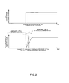
- the concentration value increases by the predetermined concentration indicated value from a time before the exhaust gas is introduced. Then, since the adsorption and the exfoliation of the NH 3 on and from the inside surface of the pipe is substantially in the equilibrium state as shown in Fig. 3 (b) , even though the NH 3 derived from the exhaust gas is adsorbed on the inside surface of the pipe, substantially the same volume of NH 3 is exfoliated from the inside surface of the pipe. Accordingly, since almost no response delay generates due to adsorption of NH 3 , it is possible for the concentration indicated value output by the gas measurement mechanism 21 to reproduce the concentration change derived from the actual exhaust gas on a substantially real time basis.
- the adsorbed volume of the NH 3 on the inside surface of the gas pipe 1 and the sampling pipe 2 is set to be saturated by introducing the injection gas prior to initiation of the engine, no NH 3 is adsorbed on the inside surface of the gas pipe 1 and the sampling pipe 2 even though a subtle volume of the NH 3 derived from the exhaust gas exists after initiation of the engine. Or even though the NH 3 is adsorbed, the NH 3 is exfoliated from the inside surface of the gas pipe 1 and the sampling pipe 2 by the same volume as that of the adsorbed NH 3 . As a result of this, as shown in Fig.
- the rise time and the fall time in the experimental conditions (1), (2) and (3) were 26s, 6s, and 2s respectively.
- the near the NH 3 approaches the saturation volume by increasing the volume of the injection gas the shorter the rise time and the fall time tend to be.
- the responsiveness regarding the NH 3 measurement of the gas measurement mechanism 21 was improved by measuring the NH 3 in the exhaust gas while NH 3 was continuously flowing from the gas injection mechanism 3 at a time of measuring the exhaust gas similar to the exhaust gas analysis device of this embodiment.
- the gas analysis device of this invention is explained as an example of the exhaust gas analysis device, however, the gas analysis device may measure other gas as the sample gas.
- the NH 3 is represented as the measurement object gas having the adsorbent characteristic, however, it may be other gas having the adsorbent characteristic such as HCl or hydrocarbon (HC) or the like.
- the hydrocarbon (HC) represented are aromatic hydrocarbons such as toluene, alcohol such as methanol or ethanol, and high boiling HC or the like.
- a gas whose adsorbent characteristic is high represented are the gas having polarity such as NO 2 , SO 2 , and H 2 O.
- the predetermined volume is set to be a volume that can keep the equilibrium state of the adsorption and the exfoliation but also the predetermined volume may be so set that a volume regarding an injection gas volume indicated by the gas measurement mechanism becomes less than or equal to an allowable difference.
- the allowable difference indicates a volume of an error that is allowable for a full-scale that can be measured by, for example, a certain measurement device, and is concretely indicated by a numerical value of about several % of the full-scale.
- the concentration indicated value derived from the injection gas falls within the error of the measurement value of the concentration allowed by the gas measurement mechanism while keeping the equilibrium state, it is possible to know a sufficiently accurate value without nearly narrowing a measurement range and without conducting an operation to deduct the concentration value derived from the injection gas from a value obtained for knowing the concentration value derived from the exhaust gas.
- the above-mentioned contamination judging part detects whether there is contamination or not based on the response time as being the value relating to the response speed of the adsorbent gas, however, the value may be the other relating value such as a rate of variability in case of changing from a certain measurement value indicated by the gas measurement mechanism to the other measurement value.
- the contamination judging part may conduct judgment based on the concentration value measured within a predetermined period of time.
- the concentration to be actually measured by injecting the span gas by means of the gas injection mechanism is set to be stepwise, however, the measurement value may be in other shape such as a rectangular wave, a sine wave or a pulse.
- whether there is contamination or not may be judged based on a time period taken from a time when the adsorbent gas is injected by the gas injection mechanism to a time when the gas is actually detected by the gas measurement mechanism.
- a portion from which the adsorbent injection gas is injected by the gas injection mechanism may be anywhere as long as it locates in the upstream side of the measurement point of the gas measurement mechanism, and the adsorbent injection gas may be injected, for example, in the sampling pipe.
- the contamination judging part not only detects whether there is contamination or not but also may judge a degree of contamination based on the measurement value.
- the response time of the non-adsorbent gas is obtained and the obtained response time of the non-adsorbent gas is substantially equal to the response time of the adsorbent gas, it may judge that maintenance of the suction pump is required or there is leakage. And in case that only the response time of the adsorbent gas is long, it may judge that there is contamination in the flow channel where the measurement object gas flows. For example, in case that there is contamination, while the response time of the adsorbent gas is aggravated and longer due to a change of the inside surface area of the pipe, the response time of the non-adsorbent gas is not affected so much even though the surface area changes and the response time hardly changes.
- the suction pump in case that the suction pump is defective, it takes time for both the adsorbent gas and the non-adsorbent gas to reach the gas measurement mechanism so that the response time becomes long for both of them.
- the gas measurement device can measure a gas composed of multiple components simultaneously, and CO, CO 2 , NO, N 2 O or the like is represented as a concrete example of the non-adsorbent gas.
- the contamination judging part is not limited to a part that is used for only the exhaust gas analysis device, and may be used for other gas analysis device.
- the above-mentioned gas measurement mechanism can measure a gas of multiple components by means of the FTIR, however, may be able to measure the adsorbent gas alone.
- the gas measurement mechanism may be able to measure the adsorbent gas alone such as NH 3 .
- the value measured by the gas measurement mechanism is not limited to the concentration, and may be a value relating to a volume such as a flow rate, a volume or the like of the adsorbent gas.
- the measurement point of the gas measurement mechanism is not limited to inside of the sampling pipe, and may be inside of the gas pipe. In short, it may be acceptable as long as the injection gas injected by the gas injection mechanism flows together with the measurement object gas from the upstream of the measurement point.
- the gas measurement mechanism is arranged in the downstream of the suction pump in the above-mentioned embodiment, however, it may be arranged in the upstream of the suction pump. Also in this case like, so called, a decompression flow, it is possible to obtain the same effect regarding the contamination detection or the measurement of the measurement object gas having the adsorbent characteristic as the above-mentioned effect.
- the adsorbent gas analysis device of this invention since it is so configured that the measurement object gas having the adsorbent characteristic is measured while injecting the injection gas having the adsorbent characteristic in the gas pipe by means of the gas injection mechanism, it is possible to provide a new coating of the injection gas immediately after being contaminated by soot or the like so that the measurement object gas is hard to adsorb on the inside surface of the gas pipe on a constant basis. As a result of this, it is possible to prevent the measurement error and the response delay of the measurement object gas. In other words, it is possible to preferably apply this invention to the exhaust gas analysis device whose measurement object is, for example, the adsorbent gas.
Landscapes
- Chemical & Material Sciences (AREA)
- Engineering & Computer Science (AREA)
- Combustion & Propulsion (AREA)
- Health & Medical Sciences (AREA)
- Life Sciences & Earth Sciences (AREA)
- Physics & Mathematics (AREA)
- General Physics & Mathematics (AREA)
- Analytical Chemistry (AREA)
- Medicinal Chemistry (AREA)
- Biochemistry (AREA)
- General Health & Medical Sciences (AREA)
- Food Science & Technology (AREA)
- Immunology (AREA)
- Pathology (AREA)
- Sampling And Sample Adjustment (AREA)
- Testing Of Engines (AREA)
Applications Claiming Priority (2)
| Application Number | Priority Date | Filing Date | Title |
|---|---|---|---|
| JP2011196360 | 2011-09-08 | ||
| PCT/JP2012/072309 WO2013035657A1 (ja) | 2011-09-08 | 2012-09-03 | 吸着性ガス分析装置及び吸着性ガス分析方法 |
Publications (1)
| Publication Number | Publication Date |
|---|---|
| EP2755013A1 true EP2755013A1 (de) | 2014-07-16 |
Family
ID=47832102
Family Applications (1)
| Application Number | Title | Priority Date | Filing Date |
|---|---|---|---|
| EP12829660.5A Withdrawn EP2755013A1 (de) | 2011-09-08 | 2012-09-03 | Vorrichtung zur analyse eines adsorptionsgases und verfahren zur analyse eines adsorptionsgases |
Country Status (5)
| Country | Link |
|---|---|
| US (1) | US20140223993A1 (de) |
| EP (1) | EP2755013A1 (de) |
| JP (1) | JPWO2013035657A1 (de) |
| CN (1) | CN103765210A (de) |
| WO (1) | WO2013035657A1 (de) |
Families Citing this family (2)
| Publication number | Priority date | Publication date | Assignee | Title |
|---|---|---|---|---|
| CN111007138B (zh) * | 2019-11-29 | 2022-08-05 | 上海电力大学 | 一种用于多通道在线气体质谱测量的时间补偿方法 |
| WO2023112597A1 (ja) * | 2021-12-15 | 2023-06-22 | 株式会社堀場製作所 | ガス分析装置、排ガス分析システム及びガス分析方法 |
Family Cites Families (6)
| Publication number | Priority date | Publication date | Assignee | Title |
|---|---|---|---|---|
| JPS5773648A (en) * | 1980-10-27 | 1982-05-08 | Mitsubishi Heavy Ind Ltd | Analyzing method for ammonia |
| JPH07333114A (ja) * | 1994-06-08 | 1995-12-22 | Toshiba Corp | 排ガス分析装置 |
| JP3817896B2 (ja) * | 1998-04-09 | 2006-09-06 | 石川島播磨重工業株式会社 | 排ガス中の無水硫酸測定方法及び装置及び無水硫酸中和装置 |
| JP2002310910A (ja) * | 2001-04-09 | 2002-10-23 | Nippon Soken Inc | ガス濃度計測装置 |
| JP4899259B2 (ja) * | 2001-06-28 | 2012-03-21 | 株式会社Ihi | So3,nh3同時連続濃度計 |
| US8256267B2 (en) * | 2008-08-14 | 2012-09-04 | Breen Energy Solutions | Method and apparatus for detection, measurement and control of sulfur-trioxide and other condensables in flue gas |
-
2012
- 2012-09-03 US US14/342,979 patent/US20140223993A1/en not_active Abandoned
- 2012-09-03 CN CN201280042315.1A patent/CN103765210A/zh active Pending
- 2012-09-03 WO PCT/JP2012/072309 patent/WO2013035657A1/ja active Application Filing
- 2012-09-03 JP JP2013532575A patent/JPWO2013035657A1/ja not_active Withdrawn
- 2012-09-03 EP EP12829660.5A patent/EP2755013A1/de not_active Withdrawn
Non-Patent Citations (1)
| Title |
|---|
| See references of WO2013035657A1 * |
Also Published As
| Publication number | Publication date |
|---|---|
| WO2013035657A1 (ja) | 2013-03-14 |
| JPWO2013035657A1 (ja) | 2015-03-23 |
| CN103765210A (zh) | 2014-04-30 |
| US20140223993A1 (en) | 2014-08-14 |
Similar Documents
| Publication | Publication Date | Title |
|---|---|---|
| RU2721669C2 (ru) | Способ (варианты) и система для выполнения самодиагностической проверки датчика оксидов азота | |
| US8307633B2 (en) | Engine exhaust gas purification apparatus enabling accurate judgement of appropriate time for terminating NOx catalyst regeneration procedure | |
| US10119448B2 (en) | Fault diagnosis apparatus for exhaust gas purification system | |
| US8930121B2 (en) | Offset and slow response diagnostic methods for NOx sensors in vehicle exhaust treatment applications | |
| JP4506874B2 (ja) | 内燃機関の排気浄化装置 | |
| EP2469259B1 (de) | Abgasanalysesystem und Abgasanalyseverfahren | |
| US8745968B2 (en) | Abnormality detection apparatus for particulate filter | |
| US20130263575A1 (en) | System and method for controlling an exhaust system having a selective catalyst reduction component | |
| WO2013035675A1 (ja) | ガス分析装置及びそれに用いられる汚れ検出方法 | |
| JP5395318B2 (ja) | 内燃機関の運転方法および装置 | |
| US10100701B2 (en) | Method for the diagnosis of an exhaust gas aftertreatment system for an internal combustion engine | |
| RU2667863C1 (ru) | Выявление и количественное определение утечек аммиака после системы избирательного каталитического восстановления оксидов азота | |
| KR101858079B1 (ko) | 내연기관의 작동 동안 상이한 배기 가스 탐침 에러를 검출하기 위한 방법 및 장치 | |
| WO2012176280A1 (ja) | 排気浄化装置の異常検出装置 | |
| US20170234195A1 (en) | Failure diagnosis apparatus for an exhaust gas purification system | |
| EP2755013A1 (de) | Vorrichtung zur analyse eines adsorptionsgases und verfahren zur analyse eines adsorptionsgases | |
| ATE435364T1 (de) | Verfahren und vorrichtung zur regenerierung des partikelfilters eines verbrennungsmotors während dessen lastwechseln | |
| JP6302593B1 (ja) | 排ガス分析装置 | |
| JP2010139281A (ja) | 排気ガス測定装置 | |
| GB2542229A (en) | Method for determining a state of aging of an NOx storage catalyst of an exhaust gas aftertreatment system of an internal combustion engine designed for | |
| Hoard et al. | NH 3 storage in sample lines | |
| Lamas et al. | Optimization of Automotive Exhaust Sampling Parameters for Evaluation of After-Treatment Systems Using FTIR Exhaust Gas Analyzers | |
| JP4494382B2 (ja) | 自動車排ガス測定装置およびそのサンプリングラインパージ方法 | |
| CN115075917A (zh) | 一种非道路柴油机scr闭环标定的试验方法和验证方法 | |
| Elwart et al. | System and method for desulfating a NO x trap |
Legal Events
| Date | Code | Title | Description |
|---|---|---|---|
| PUAI | Public reference made under article 153(3) epc to a published international application that has entered the european phase |
Free format text: ORIGINAL CODE: 0009012 |
|
| 17P | Request for examination filed |
Effective date: 20140311 |
|
| AK | Designated contracting states |
Kind code of ref document: A1 Designated state(s): AL AT BE BG CH CY CZ DE DK EE ES FI FR GB GR HR HU IE IS IT LI LT LU LV MC MK MT NL NO PL PT RO RS SE SI SK SM TR |
|
| DAX | Request for extension of the european patent (deleted) | ||
| STAA | Information on the status of an ep patent application or granted ep patent |
Free format text: STATUS: THE APPLICATION HAS BEEN WITHDRAWN |
|
| 18W | Application withdrawn |
Effective date: 20150127 |